1
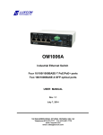
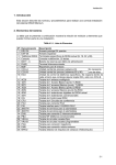
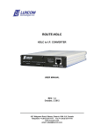
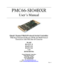
OM12-SFP
FIBER OPTIC
DATA/VOICE MULTIPLEXER
USER MANUAL
REV. 2.2
December 19, 2012
102 WALGREEN ROAD, OTTAWA, ONTARIO, K0A 1L0
Telephone +1(613)831-7777 Fax +1(613) 831-7778
www.luxcom.com
email: [email protected]
20/12/12
II
Table of Contents
GENERAL......................................................................................................... 1
Specifications* ................................................................................................................ 1
FRONT PANEL................................................................................................. 2
REAR PANEL................................................................................................... 4
INTERFACE MODULES .................................................................................. 5
Interface A....................................................................................................................... 5
Interface B....................................................................................................................... 5
INTERNAL JUMPERS...................................................................................................... 6
ACCESSORIES................................................................................................ 7
Mounting Panel................................................................................................................ 7
Power Cube...................................................................................................................... 7
INSTALLATION................................................................................................ 7
Multiplexer Mounting......................................................................................................
Connecting The Power Supplies...................................................................................
Connecting The Optical Cables.....................................................................................
Reading Multiplexer Status............................................................................................
Updating the Multiplexer Software................................................................................
7
7
8
8
8
TROUBLE SHOOTING..................................................................................... 9
ORDERING INFORMATION.......................................................................... 11
Optical Options.............................................................................................................. 11
Electrical Interface Options.......................................................................................... 11
INTERFACES................................................................................................. 12
RS-232 INTERFACE....................................................................................................... 12
RS-422 INTERFACE....................................................................................................... 15
ANALOG AND DATA INTERFACE................................................................................ 17
ANALOG AND DATA RADIO INTERFACE.................................................................... 19
CONTACT CLOSURE INTERFACE............................................................................... 22
RELAY CONTROL INTERFACE.................................................................................... 25
TELEPHONE INTERFACES........................................................................................... 29
OM12-1CO............................................................................................................................... 29
OM12-1SL................................................................................................................................29
OM12-EOW..............................................................................................................................29
OM12-4CO............................................................................................................................... 29
OM12-4SL................................................................................................................................30
OM12E- 7 Line Telephone Expansion Chassis........................................................... 31
01/03/2010
I
Manual Revision Record
Revision 2.0 March 1, 2010. Added SFP Formatting, Relay 1 section added, updated figures
Revision 2.1 March 31, 2010. Error of relay card pin-out corrected
Revision 2.2 December 19, 2012 Title changed and formatting changes.
01/03/2010
II
GENERAL
Description
The OM12-SFP is a compact multiplexer with 14 internal data channels. A variety of interfaces are available
that use some or all of these channels. Each channel is transparent to data rates up to 64 kbps. The OM12
has a front daughter board for a single telephone channel option; as well, it has a rear daughter board for the
main interface option. The single telephone option connects to the subscriber’s telephone at one end and to
the Central Office line (or PBX) at the other end. Alternatively, the voice channel may be used as an order
wire (dedicated voice link).
The multiplexer can also be expanded to support an additional 7 standard telephone lines by using a special
expansion card and OM12E telephone expansion chassis.
The distance between OM12s may be up to 20 km for multimode fiber, and 50 km for singlemode versions.
Greater transmission distances are possible with high output multimode or single mode optical module
options. A built-in optical power meter simplifies system installation and system maintenance. An external
power cube supplies power and a second power cube may be used for redundancy. Alarm contacts on the
rear of the OM12 signal power supply or optical link failure.
Specifications*
Optical
Light source
MM version ....................................................................
SM version......................................................................
Optical output MM version 62./125 fiber................................................
SM version 9/125 fiber.................................................
Photo detector MM or SM version..........................................................
Optical sensitivity (10-9BER) MM or SM version ...................................
Optical connectors ................................................................................
1300nm LED
1300nm LASER
> -18 dBm
> -13 dBm
PIN, InGaAs
>-35 dBm
LC
Typical operating distance
MM version 62/125 (0.7dB/km)......................................................... 0 to 20 km
SM version 9/125 (0.4dB/km).......................................................... 0 to 50 km
Electrical
Number of Independent Data Channels.................................................
Data I/O connector.................................................................................
Power Source (supplied)........................................................................
Supply voltage range..............................................................................
Power consumption................................................................................
14 maximum
see Interfaces
12V DC output AC adapter
11 to 16V DC
varies with option cards
General
Operating Temperature .........................................................................
Humidity (RH) .......................................................................................
Dimensions (W*H*D) ............................................................................
Weight....................................................................................................
MTBF.....................................................................................................
* Specifications subject to upgrade without notice.
OM12 manual
1
-40ºC to 74ºC
10% to 95% (non-condensing)
18 cm * 4 cm * 25 cm
1 Kg
100,000 hrs
FRONT PANEL
13
1
2 3
4
5
6 7
8 9 10 11 12
14 15 16
17
OM12 Front Panel View
1
PWR 1 :
This indicator shows the presence of electrical power at the PS 1 connector on the rear panel.
2
PWR 2 :
This indicator shows the presence of electrical power at the PS 2 connector on the rear panel. Note
that if only a single supply is to be used, the internal shunt J5 must be in position 1, 2.
3
LINK :
This indicator shows the of presence of sufficient optical power at the RX optical connector of the rear
panel. ( > -37dBm)
4
DIS. EN. :
Typically an external audible alarm is connected to the three-terminal ALARM block on the rear of the
modem. During an alarm condition (one or both of the external power supplies fails or the RX optical
link fails) the connection between the Normally Closed (N.C.) contact and the Common (COM) is
broken. As well, the Normally Open (N.O.) is connected to the Common contact. The Alarm Disable
Switch restores the three terminal block to the non-alarm condition even if the modem is not powered
up . The red Alarm LED is unaffected by the switch.
The alarm monitor can be factory set to only monitor power supply 1 by moving J5 to position 1,2. In
this case the presence or absence of Power Supply 2 will not cause an alarm.
5
ALARM LED :
This Red indicator shows the loss of optical power or the loss of one of the power supplies when dual
supplies are used.
6,7
LOCAL LOOP BACK :
To activate, press and hold the switch for approximately one second. Activating the Local Loopback
switch causes the following:
1) The transmitted data for all channels (except ch 13) is looped back to the
receive port.
2) The transmitted data from the remote modem is ignored by the local modem.
OM12 manual
2
3) The received data at the remote modem is put into the idle state.
4) The Local Loopback LED at the end where the switch was pushed is on solid.
5) The Local Loopback LED at the remote modem flashes.
6) Once Local Loopback has been initiated at the far end, activating the Local Loopback Switch at
the local end will cancel that loopback.
8,9
REMOTE LOOP BACK :
To activate, press and hold the switch for approximately one second. Activating the Remote
Loopback switch causes the following:
1) The transmitted data for all channels passes to the remote modem where it is
retransmitted back (except ch 13) to the originating end.
2) The transmitted data at the remote modem is ignored.
3) The received data at the remote modem is put into the idle state.
4) The Remote Loopback LED at the end where the switch was pushed is on .
solid.
5) The Remote Loopback LED at the remote modem flashes.
6) If Remote Loopback has been initiated from the far end, activating the
Remote Loopback Switch at the local end will cancel that loopback.
10,11 CH. SELECT :
The CH SELECT switch toggles the indicator mode.
When this indicator is on, the TX and RX Indicators are monitoring data activity on ports 1 to 6.
When the indicator is off, the TX and RX indicators are monitoring data activity on ports 7 to 12.
12
TX INDICATORS :
These indicators are on during transitions on the data outputs of the channels as explained above.
13
RX INDICATORS :
These indicators are on during transitions on the data inputs of the channels as explained above.
14
CO INT :
On when the option B card which interfaces to a CO/PBX is installed .
15
SL INT :
On when the option B card which interfaces to a telephone is installed .
16
BUSY :
ON when the telephone is ringing or off-hook.
17
TELEPHONE INTERFACE :
This RJ-11 connects to a telephone set or PBX when interface B is installed.
OM12 manual
3
REAR PANEL
1
PS 1 :
Input Power Connector one. It accepts 11V to 16V DC. The presence of power turns on the PWR 1
indicator on the front panel. The power connector locks into place by turning it.
2
PS 2 :
Redundant Input Power Connector two. It accepts 11V to 16V DC. The presence of power turns on
PWR 2 indicator on the front panel. When two power supplies are used, jumper J5 should be in
position 2,3. In this state, the OM12 will Alarm on the removal of PS 1 or PS 2. See the Internal
Jumpers section.
3
ALARM :
Dry contacts N.O., N.C. And COM. The contacts are normally energized, so loss of electrical power or
loss of optical power will cause the contacts to change state. The contacts may be wired to external
visual or aural alarm.
4
CONSOLE:
A serial port, used for multiplexer status information, as well as for updating firmware and software.
It's accessed using the RS232 port of a PC and some terminal program such as HyperTerminal. Port
settings are 38400, 8, No Parity, 1 stop bit and no Flow control. The console port operation is
straightforward with its built in menu.
5
INPUT/OUTPUT CONNECTORS :
Connectors depend on module installed in module location A of the OM12.
6
TX , RX:
Optical output and input ports, LC connection. Output wavelength and power is dependent on type of
light source installed.
7
RX POWER:
A built-in optical power meter for measuring the optical received power on the RX port. When optical
power is received, 2 LEDs will be on; one in the Tens column and one in the Units column. Summing
the two numbers yields the received optical power.
OM12 manual
4
INTERFACE MODULES
The following two pictures show the inside of the OM12. It may contain one or two option modules.
Interface A
Interface A is located at the right center of the following picture. The following interfaces are available .
RS-422 6 synchronous/12 asynchronous channels
RS-232 5 synchronous/10 asynchronous channels
Telephone 4 channel Central Office Interface
Telephone 4 channel Subscriber Loop Interface
Relay Control -- 1 FSK + 3 relay contact + 3 relay driver + 1 RS232
Dual 2 Wire/4 Wire + 2 bidirectional dry contacts + 5 RS-232 channels
28 bi-directional dry contacts
Telephone 7 channel expansion chassis
Other interfaces available on required.
Interface B
Interface A is located at the left of the following picture. The following modules are available
Telephone, one Central Office / PBX interface
Telephone, one Subscriber telephone set interface
Engineering Orderwire dedicated telephone link
OM12 manual
5
INTERNAL JUMPERS
There are a number of jumpers on the main printed circuit card, as shown below. Some of the jumpers should
not be moved at all, while others are module specific and are set at the factory. The table below indicates the
correct setting for each jumper. In order to access the jumpers, the following steps should be followed.
1. Remove the two front panel phillips screws.
2. Pull the front panel and bezel off the case.
3. Slide the top cover off, by pulling it forward.
4. Set the jumpers in the desired position.
5. Reassemble.
JUMPER
SETTING
J5
2,3
1,2
When two power supplies are used
When a single Power supply is used (part of alarm function)
J7
2,3
1,2
+24V applied to Option card A
No +24V applied to option card
J8
2,3
1,2
+120V low current DC applied to option card A
No +120V DC applied to option card A
Used when OM12-4-4SLI-600 Option A card installed. (Ringing voltage supply)
Not used with any other option card.
J14
ON
Disables loopback function on all channels. Used with 4 channel telephone
module.
J15
ON
Enables level sensing on TX and RX LEDs. Used with 4 channel telephone
module.
OM12 manual
DESCRIPTION
6
ACCESSORIES
Mounting Panel
MP4
This is a 19 inch, 1RU mounting panel for 2 modems. The basic unit comes complete with all necessary
mechanical hardware, with the exception of the mounting screws necessary to attach the panel to the rack.
Power Cube
LTIPS-12-1U
Optional Universal Power Supply can be used world
wide. Wall plug may be replaced with one conforming
to local standards.
INSTALLATION
Multiplexer Mounting
The OM12 may be used as a stand alone unit, or may be rack mounted using a 19" 1U high rack mount panel
(MP4) which is available as a separate order. This panel will mount up to two OM12s.
If the multiplexer is to be rack mounted, proceed as follows:
1. Insert the OM12 through the mounting panel from the rear and fasten using the 4-40X1/4 phillips screws
supplied.
2. Mount the mounting panel in the 19" rack. Fit the two supplied brackets where the Mounting Panel attaches
to the 19" rack.
Connecting The Power Supplies
The OM12 is supplied with an AC adapter LTIPS-12-1U which converts the 90-240V AC mains voltage to
12V DC.
Connect the power plug to the PS 1 receptacle of the OM12. Plug the supplied power cube into the Mains line.
The PWR 1 indicator on the front panel will light.
If the OM12 was ordered with dual power option, then follow the above procedure with the second power
cube, but attach this one to the PS 2 receptacle of the OM12. In this event, PWR 2 will come ON at this point.
Note that the second power cube is normally connected to a separately fused AC source.
OM12 manual
7
Connecting The Optical Cables
The OM12 uses an SFP (Small Form Pluggable) fiber optic module. The type installed depends on the
customer's requirements, and will be marked on a label affixed to the top front of the multiplexer.
The TX fiber at one end connects to the RX fiber at the far end. The Link indicator will be on once the fibers
are connected and the alarm condition will disappear.
Reading Multiplexer Status
The Console port (see rear panel section) can be used to access various operating parameters of the
multiplexer, such as Transmitted Optical Power, Received Optical power, Internal Temperature and the 3.3V
Power Rail. It can also provide the status of various internal registers, in the event of an optical port
malfunction.
The Console port may be accessed using a supplied console cable and an appropriate Terminal software
such as HyperTerm. The terminal program is to be set to 38400, 8, No Parity, 1 stop bit and no Flow control.
Set up the Terminal program as above, connect the cable between the PC and the OM12 and power the
OM12. A menu will come up as follows:
Luxcom Technologies Inc.
OM12 Optical Modem
OM12 BootLoader 1.0 Feb 26 2010 13:22:53
OM12 Application 1.0 Mar 19 2010 13:50:20
Main Menu
1 Show SFP Diagnostic Values
2 Show SFP registers
3 Firmware upload menu
4 Software upload menu
5 Reset modem
6 Set password
Esc Back
:>
Selecting menu item 1 will display various operating parameters shown below
:> 1
SFP Diagnostic Values
Parameter Units
Value High Low
High
Low
Alarm
Alarm
Warning
Warning
T
C 34.6
110.0
-40.0
93.0 -30.0
Vcc
V 3.31 3.90 2.70
3.70
2.90
TX Bias
mA 19.2 80.0 2.0
70.0
4.0
TX Power dBm
-11.8 -6.0
-17.0
-8.0 -15.0
RX Power dBm
-44.0 -6.0
-30.0
-8.0 -28.0
Note the listing of Temperature (T), Power Rail (VCC), TX Power and RX Power. The -44dBm above is
without an optical input.
Updating the Multiplexer Software
Periodically, Luxcom will release new software revisions and/or firmware revisions. The modems may be
updated using the Console port as above. Starting with the menu below, the user will select Option 3 or
Option 4, depending on whether the software or the firmware is being updated.
Luxcom Technologies Inc.
OM12 Optical Modem
OM12 BootLoader 1.0 Feb 26 2010 13:22:53
OM12 Application 1.0 Mar 19 2010 13:50:20
Main Menu
1 Show SFP Diagnostic Values
2 Show SFP registers
3 Firmware upload menu
4 Software upload menu
5 Reset modem
OM12 manual
8
6 Set password
Esc Back
Selecting Option 3 for example gives the following menu
:> 3
Firmware Upload Menu
1 Show stored files
2 Upload new BACKUP
3 Swap BACKUP and PRIMARY
4 Reprogram card with PRIMARY
Esc Back
:>
There are two copies of the program stored in the multiplexer; the primary (currently used) and the secondary.
We always upload to the backup location (menu item 2), overwriting the old backup, then we swap the primary
with the new backup (menu item 3). This way we do not destroy the original program and we have the ability
to revert should something go wrong.
TROUBLE SHOOTING
1. Power one and link should be lit.
No Power LED indication; check that the power adapter(s) are connected and powered.
No Link LED; check the Power Meter indication on the rear of the multiplexer. If no received power is
indicated, check that the TX and RX fibers are not reversed. If still no link, the fiber may be defective
2. Local loopback, remote loopbackand all lower tx leds will flash if there is no link and the OM12 is detecting
ambient light but cannot synchronize with the incoming signal due to errors.
3. PWR indicator NOT on.
Check that the power cube outputs 12-16V.
The internal fuse is self resetting: therefore if the power LED will not come on, it indicates an internal fault with
the modem, and it must be returned to the factory.
4. LINK indicator NOT on.
Check that the TX and RX optical fibers are not reversed. Check that the received optical power is greater
than -36 dBm, using the built-in power meter, located on the rear of the unit, next to the optical module. If no
power is present, check that the modem at the far end is powered up.
OM12 manual
9
WARRANTY
This Luxcom product is warranted against defects in materials and workmanship for a period of five years
from the date of shipment. Luxcom will, at its option, repair or replace products that prove to be defective
during the warranty period provided they are returned to Luxcom . Repairs necessitated by misuse of the
product are not covered by this warranty.
NO OTHER WARRANTIES ARE EXPRESSED OR IMPLIED, INCLUDING, BUT NOT LIMITED TO , THE
IMPLIED WARRANTIES OF MERCHANTABILITY AND FITNESS FOR A PARTICULAR PURPOSE.
LUXCOM TECHNOLOGIES INC. IS NOT LIABLE FOR CONSEQUENTIAL DAMAGES.
CLAIMS
The warranty statement applicable to the fiber optic modem is printed inside the front cover. If physical
damage to the modem is found when the product is received, notify the carrier and Luxcom Technologies Inc.
immediately. Luxcom Technologies Inc. will arrange for repair or replacement.
REPACKAGING FOR SHIPMENT
If the modem needs to be shipped by commercial transportation for service or repair, it is recommended that it
be packaged in the original manner.
Before returning the item, paperwork indicating the name, department, company and telephone number of the
sender, model and serial number of the product and a brief description of the problem should be enclosed. As
well, the sender must also request a Return Authorization number from Luxcom Technologies Inc. See front
cover for shipping address.
CERTIFICATION
Luxcom Technologies Inc. certifies that this modem met its published specification at the time of shipment
from the factory.
OM12 manual
10
ORDERING INFORMATION
Typically, the OM12 is configured at the factory. Interface B modules can be added in the field, but changing
Interface A typically requires a change of rear panel as well, thus making field configuration more difficult.
Optical Options
The optical option required for a given application is determined by the type of fiber used (50/125, 62.5/125 or
9/125), and the distance over which the system is to operate. The Optical Specifications are to be used for
determining the optics.
Electrical Interface Options
There is a variety of option cards available for the OM12
When ordering the OM12, specify the following model numbers:
main chassis
one Interface A
one Interface B if desired
a telephone expansion chassis if desired
Main Chassis
OM12-MM-LC
OM12-SM-LC
1300nm version
1300nm version for long distance (singlemode fiber)
Interface A
OM12-12E2
OM12-6-422
OM12-2W4W
OM12-RLY1
OM12-RLY2
OM12-4CO
OM12-4SL
5 RS-232 data channels + interface for OM12E expansion chassis
6 synchronous or 12 asynchronous RS-422 data channels
Voice/Data/PTT application
3 sense/contact channels, 3 sense/open-collector channels, RS232 and voice
28 relay contact closures
4 telephone lines for interface to a CO/PBX
4 telephone lines for interface to a telephone
Interface B
OM12-COI-600
OM12-SLI-600
OM12-EOW
1 telephone line interface to a CO/PBX
1 telephone line interface to a telephone
1 telephone line interface to a create a dedicated engineering order wire
Telephone Expansion Chassis
OM12E-CO
OM12E-SL
7 telephone line expansion chassis for interface to the CO/PBX
7 telephone line expansion chassis for interface to telephones
Accessories
MP4
LTIPS-12-0.8-1
LTIPS-12-1U
Rack mounting panel
12V DC Unregulated wall transformer (117V 60Hz) One supplied per modem
12V DC Universal supply for world wide use (optional)
ORDERING EXAMPLE
Suppose the following fiber optic link is required.
Distance between ends............................................ 10 km
Type of fiber installed............................................... 9/125 singlemode
Signals to be transported......................................... 4 RS-232, 6 telephone lines
Equipment needed on CO/PBX end
Equipment needed on telephone set end
1
1
1
1
1
1
1
1
OM12-SM-LC
OM12-12E2
OM12E-CO7
MP-OM12
OM12-SM-LC
OM12-12E2
OM12-SL7
MP-OM12
This will provide 5 synchronous or 10 asynchronous RS-232 lines, and 7 telephone lines.
OM12 manual
11
INTERFACES
The available option cards and modules are described in this section.
RS-232 INTERFACE
The OM12 -12E2 option card is plugged
into the rear option slot (A) of the OM12.
The card provides five bi-directional
asynchronous RS-232 data ports with
control lines or 10 without control lines. The
card also provides an expansion port for an
OM12E (7 telephone lines).
The ports may also be used to carry
synchronous data where a clock signal is
carried along with the data. In this mode no
control lines are available.
OM12-12E2 Module
SPECIFICATION
Number of asynchronous channels.....................................................
Data format.........................................................................................
Data rate.............................................................................................
Connector type....................................................................................
Output voltage....................................................................................
Number of Expansion Ports................................................................
5
RS-232C
0-64 K baud
RJ-45 (8 conductor)
+/- 6 Volts
1
I/O CONNECTIONS
The data ports are are implemented using standard RS-232 drivers and receivers, compliant to the RS-232C
and CCITT V.24 standards. Data ports are accessed through connectors J1 through J4 and J6. When an
OM12E telephone expansion chassis is to be connected, it is connected through J8.
Connector and Jumper Locations
The diagram shows the location of the I/O connectors and programming jumpers.
There are 10 jumpers on the card, 2 to each data I/O port.
Each port can be configured independently.
The table on the next page shows settings of the appropriate jumpers.
OM12 manual
12
CONN.
JUMPER SETTING
ASYNCHRONOUS
JUMPER SETTING
SYNCHRONOUS
J1
W8 1-2
W7 2-3 HANDSHAKE
W7 1-2 NO HANDSHAKE
W8 2-3
W7 1-2
J2
W6 1-2
W5 2-3 HANDSHAKE
W5 1-2 NO HANDSHAKE
W6 2-3
W5 1-2
J3
W4 1-2
W2 2-3 HANDSHAKE
W2 1-2 NO HANDSHAKE
W4 2-3
W2 1-2
J4
W3 1-2
W1 2-3 HANDSHAKE
W1 1-2 NO HANDSHAKE
W3 2-3
W1 1-2
J6
W10 1-2
W9 2-3 HANDSHAKE
W9 1-2 NO HANDSHAKE
W10 2-3
W9 1-2
"FIBER"
TX DATA
2
2
TX DATA
DTE READY
8
8
DTE READY
RTS
5
5
RTS
4
DCE READY
+5V
+5V
3 2 1
LINK
1 2 3
LINK
DCE READY
4
RX DATA
3
3
RX DATA
CTS
6
6
CTS
SIGNAL GND
1
1
SIGNAL GND
7
7
NOTE 1
NOTE 1
REMOTE END
LOCAL END
RS-232 Asynchronous Connection
"FIBER"
TX DATA 2
2
TX DATA
TX CLOCK 8
8
TX CLOCK
RX DATA 3
3
RX DATA
RX CLOCK 6
6
RX CLOCK
SIGNAL GND 3
3
SIGNAL GND
SIGNAL GND 1
1
SIGNAL GND
SIGNAL GND 5
5
SIGNAL GND
SIGNAL GND 7
7
SIGNAL GND
LOCAL END
REMOTE END
RS-232 Synchronous Connection
OM12 manual
13
RS-232 CONNECTION
The recommended interconnect cable is the same as RS232-B specification. Typically cable lengths of 50 feet
are acceptable up to 19.2K baud. If data rates above 19.2K baud are used, the cable must be shortened
correspondingly. At 64K baud cable lengths should be less than two meters. Flat silver satin cable is
acceptable. A cable shield can be connected the grounding lug on the rear panel if desired.
Pin assignments of the data ports are given below.
1
2 3
4
5 6 7
8
RJ-45
Pin #
1
2
3
4
5
6
7
8
Circuit Description
Signal Common (Gnd)
TXD (Input)
RXD (Output)
DSR (Output)
RTS (Output)/ or Gnd
CTS/RXCLK
Gnd
DTR/TXCLK
EXPANSION PORT (J8)
The Expansion port is used to connect optional chassis such as the OM12E-CO or the OM12-SL to the
OM12. The interface provides power, timing signals, data input and data output connections between the
OM12 and the OM12E chassis.
When OM12E-CO and OM12E-SL are ordered as an option, the interconnect cables are supplied with the
OM12E chassis.
1
2 3
OM12 manual
4
5 6 7
8
RJ-45
Pin #
Circuit Description
1
2
3
4
5
6
7
8
Signal Common (Gnd)
H.S. CLOCK OUT (Output)
+12V D.C. (Output)
RX DATA (Input)
TX FRAME (Output)
Signal Common (Gnd)
RX-FRAME (Output)
TX DATA (Output)
14
RS-422 INTERFACE
OM12-6-422
The OM12-6-422 card provides RS-422 interfaces and
provides 6 synchronous or 12 asynchronous data
channels. RS-422 has balanced drivers with a nominal
output voltage of 2.5 volts (loaded) on one driver and 0
volts on the complement. The receiver has
corresponding balanced inputs. Transmission is data
rate transparent up to 64 k baud. Each data channel is
associated with a transmit (TX) and receive (RX) front
panel LED. This LED flashes during activity on the data
channel.
The user I/O consists of 6 identical RJ-45 data ports,
J1 to J6. There are no user settings on this card.
OM12-6-422 Interface Module
SPECIFICATION
Data Format........................................................................................
Data rate.............................................................................................
No. of Duplex channels per connector................................................
No. of connectors................................................................................
Connector type....................................................................................
RS-422
0-64 K baud
2 (clock+ data)
6
RJ-45 (8 conductor)
I/O CONNECTIONS
Recommended interconnect cable is category 4 or 5 shielded twisted pair; however, flat silver satin cable
works if the run is less than one meter. The cable shield can be connected the grounding lug on the rear panel
if desired.
RJ-45
Pin #
1
2
3
4
5
6
7
8
Circuit Description
TXD1+ (input)
TXD1- (input)
TXC1+ (input)
TXC1- (input)
RXD1+ (Output)
RXD1- (Output)
RXC1+ (Output)
RXC1- (Output)
TX DATA
TX CLOCK
RX DATA
RX CLOCK
1
1
"FIBER"
2
2
3
3
4
4
5
5
6
6
7
7
8
8
LOCAL OM12
REMOTE OM12
Illustration 1 One Data/Clock Channel
OM12 manual
15
TX DATA
TX CLOCK
RX DATA
RX CLOCK
OM12-6-422S1
The OM12-6-422S1 card is a modified version of the
OM12-6-422 card. It provides 8 RS-422 ports and 4 TTL
compatible ports. RS-422 has balanced drivers with a
nominal output voltage of 2.5 volts (loaded) on one
driver and 0 volts on the complement. The receiver has
corresponding balanced inputs. Transmission is data
rate transparent up to 64 Kbaud. Each data channel is
associated with a transmit (TX) and receive (RX) front
panel LED. This LED flashes during activity on the data
channel.
Connectors 1 to 4 contain two bi-directional RS-422
ports each. Connectors 5 and 6 contain two bidirectional TTL compatible ports in each.
OM12-6-422S1 Interface Module
SPECIFICATION
Data Format ( connectors 1-4)............................................................
Data rate.............................................................................................
No. of Duplex channels per connector................................................
Connector type....................................................................................
Data Format ( connectors 5 and 6).....................................................
Data rate.............................................................................................
No. of Duplex channels per connector................................................
Connector type....................................................................................
RS-422
0-64 K baud
2
RJ45 (8 conductor)
TTL compatible
0-64 K baud
2
RJ45 (8 conductor)
I/O CONNECTIONS
RJ-45
Pin #
1
2
3
4
5
6
7
8
RJ-45
Pin #
1
2
3
4
5
6
7
8
Circuit Description
Connectors 1 to 4
TXD1+ (input)
TXD1- (input)
TXD2+ (input)
TXD2- (input)
RXD1+ (Output)
RXD1- (Output)
RXD2+ (Output)
RXD2- (Output)
TX DATA
TX CLOCK
RX DATA
RX CLOCK
1
2
1
"FIBER"
2
3
3
4
4
5
5
6
6
7
7
8
8
LOCAL OM12
TX DATA
TX CLOCK
RX DATA
RX CLOCK
REMOTE OM12
Illustration 2 RS-422 I/O port
Circuit Description
Connectors 5 and 6
TXD1+ (input)
TXD1 Gnd
TXD2+ (input)
TXD2 Gnd
RXD1+ (Output)
RXD1- (Output)
RXD2+ (Output)
RXD2- (Output)
Illustration 3 TTL I/O Port
Recommended interconnect cable is category 4 or 5 shielded twisted pair; however, flat silver satin cable
works if the run is less than one meter. The cable shield can be connected the grounding lug on the rear panel
if desired.
OM12 manual
16
ANALOG AND DATA INTERFACE
The OM12-2W4W module provides the user with 2
analogue voice grade ports which may be configured
either for balanced 2 wire or balanced 4 wire operation.
The card also provides 6 full duplex RS-232D channels
and 2 bi-directional contact closures.
OM12-2W4W Analog Interface
There are two jumpers, one for each analogue channel
for selecting 2 wire or 4 wire operation and two
potentiometers
which
are
factory
set.
The
potentiometers,, one per analogue channel, set the loop
gain of the analogue channel. The default setting is for a
loop gain of 0dB nominal.
Caution there must be no dc on the inputs or damage
maybe done to the module.
SPECIFICATIONS
Analog Channels
Number of Analog channels................................................................
Input/Output impedance......................................................................
Analog Bandwidth...............................................................................
Analog Input Level..............................................................................
Maximum Analog Input.......................................................................
Analog Insertion Gain.........................................................................
Encoding.............................................................................................
Idle Channel Noise..............................................................................
Connector (All I/O)..............................................................................
2 (2W or 4W)
600 ohms
180 Hz to 6 Khz
0 dBm
+6 dBm
+/- 2 dB
13 bit linear
< 30 dBrnco
62 Pin, high density
mating part supplied
Data Channels
Data Format........................................................................................ RS-232 D
Data rate............................................................................................. 0-64 K baud
No. of Duplex channels....................................................................... 6
Contact Closure
Sensing inputs (ground to activate) ....................................................
Sensing Input Characteristics.............................................................
Contact Outputs..................................................................................
Contact Rating....................................................................................
2
5.1KΩ to 5V
2 independent Form C contacts
0.5A @ 125 VAC, 2A @ 30 VDC
ANALOG PORTS
Jumper Settings
Analog channels 1 and 2 can be set as 2 wire
balanced or 4 wire balanced. With W1 in position
1,2, analogue channel 1 is set for 2 wire balanced
operation. When W1 is set to position 2,3,
operation of channel 1 is 4 wire balanced.
With W2 in position 1,2, analogue channel 2 is set
for 2 wire balanced operation. When W2 is set to
position 2,3, operation of channel 2 is 4 wire
balanced. The inputs and outputs appear on J1.
Analog Option Jumper Locations
OM12 manual
17
Pin Assignments
PIN FUNCTION
AUDIO MODE
J1 PIN
Audio 1 Input +
4 Wire balanced
2
Audio 1 Input -
4 Wire balanced
23
Audio 1 Output +
4 Wire balanced
1
Audio 1 Output -
4 Wire balanced
22
Audio 1 Input/Output +
2 Wire balanced
1
Audio 1 Input/Output -
2 Wire balanced
22
Audio 2 Input +
4 Wire balanced
5
Audio 2 Input -
4 Wire balanced
26
Audio 2 Output +
4 Wire balanced
4
Audio 2 Output -
4 Wire balanced
25
Audio 2 Input/Output +
2 Wire balanced
4
Audio 2 Input/Output -
2 Wire balanced
25
Grounds
Any
3,6,24,27
RS-232 Data Ports
PIN FUNCTION
INPUT
OUTPUT
RS-232 Channel 1
11
36
RS-232 Channel 2
12
32
RS-232 Channel 3
14
33
RS-232 Channel 4
15
34
RS-232 Channel 5
16
35
RS-232 Channel 6
18
Grounds
39
43-47
Contact Ports
PIN FUNCTION
PIN #
Contact Sense 1 Input
13
Contact Sense 2 Input
17
Grounds
52 to 62
Dri Contact 1Output Common
50
Dri Contact 1Output NC
30
Dri Contact 1Output NO
9
Dri Contact 2 Output Common
51
Dri Contact 2 Output NC
31
Dri Contact 2 Output NO
10
OM12 manual
18
ANALOG AND DATA RADIO INTERFACE
The OM12-VIN1 module provides the user with 2 analog
voice grade ports which may be configured either for
balanced 2 wire or balanced 4 wire operation.
The card also provides a duplex wideband unbalanced
analog channel, 6 full duplex RS-232D channels and 2
bi-directional contact closures.
There are two jumpers, one for each analog channel for
selecting 2 wire or 4 wire operation and two
potentiometers
which
are
factory
set.
The
potentiometers,, one per analog channel, set the loop
gain of the analog channel. The default setting is for a
loop gain of 0dB nominal.
OM12-VIN1 Analog and Data
SPECIFICATIONS
Analog Channels
Number of Analog channels................................................................
Input/Output impedance......................................................................
Analog Bandwidth...............................................................................
Nominal Analog Input Level................................................................
Maximum Analog Input level...............................................................
Analog Insertion Gain.........................................................................
Encoding.............................................................................................
Idle Channel Noise..............................................................................
Connector (All I/O)..............................................................................
2 (2W or 4W)
600 ohms
180 Hz to 6 Khz
0 dBm
+6 dBm
+/- 2 dB
12 bit linear
< 30 dBrnco
62 Pin, high density
mating part supplied
Wideband Analog Channel
Number of Analog channels................................................................
Input/Output impedance......................................................................
Analog Bandwidth...............................................................................
Analog Input Level..............................................................................
Maximum Analog Input.......................................................................
Analog Insertion Gain.........................................................................
Encoding.............................................................................................
Connector (All I/O)..............................................................................
1, Unbalanced
600 ohms
DC to 21 Khz
0 dBm
+6 dBm
+/- 2 dB
13 bit linear
62 Pin, high density
mating part supplied
Data Channel
Data Format........................................................................................ RS-232D
Data rate............................................................................................. 0-64 K baud
No. of Duplex channels....................................................................... 6
Contact Closure
Sensing inputs (ground to activate) ....................................................
Sensing Input Characteristics.............................................................
Contact Outputs..................................................................................
Contact Rating....................................................................................
OM12 manual
19
2
5.1KΩ to 5V
2 independent Form C contacts
0.5A @ 125 VAC, 2A @ 30 VDC
ANALOG SIGNAL PORTS
Jumper Settings
Analog channels 1 and 2 can be set as 2 wire
balanced or 4 wire balanced. With W1 in position
1,2, analog channel 1 is set for 2 wire balanced
operation. When W1 is set to position 2,3,
operation of channel 1 is 4 wire balanced.
With W2 in position 1,2, analog channel 2 is set for
2 wire balanced operation. When W2 is set to
position 2,3, operation of channel 2 is 4 wire
balanced. The inputs and outputs appear on J1.
Analog Option Jumper Locations
Pin Assignments
PIN FUNCTION
AUDIO MODE
J1 PIN
Audio 1 Input +
4 Wire balanced
2
Audio 1 Input -
4 Wire balanced
23
Audio 1 Output +
4 Wire balanced
1
Audio 1 Output -
4 Wire balanced
22
Audio 1 Input/Output +
2 Wire balanced
1
Audio 1 Input/Output -
2 Wire balanced
22
Audio 2 Input +
4 Wire balanced
5
Audio 2 Input -
4 Wire balanced
26
Audio 2 Output +
4 Wire balanced
4
Audio 2 Output -
4 Wire balanced
25
Audio 2 Input/Output +
2 Wire balanced
4
Audio 2 Input/Output -
2 Wire balanced
25
Grounds
Any
3,24
Wideband Audio In
7
Wideband Audio In Gnd
6
Wideband Audio Out
28
Wideband Audio Out Gnd
27
RS-232 Data Ports
PIN FUNCTION
INPUT
OUTPUT
RS-232 Channel 1
11
36
RS-232 Channel 2
12
32
RS-232 Channel 3
14
33
RS-232 Channel 4
15
34
RS-232 Channel 5
16
35
RS-232 Channel 6
18
39
Grounds
OM12 manual
43-47
20
Contact Ports
PIN FUNCTION
PIN #
Contact Sense 1 Input
13
Contact Sense 2 Input
17
Grounds
52 to 62
Dri Contact 1Output Common
50
Dri Contact 1Output NC
30
Dri Contact 1Output NO
9
Dri Contact 2 Output Common
51
Dri Contact 2 Output NC
31
Dri Contact 2 Output NO
10
INTERCONNECT CABLES
A pair of OM12 fibre optic modems equipped with OM12-VIN1 modules can be used to interconnect the
CABINET LAND VINSON to the AN/GRC-171 radio. Two different cables are required, one to connect the
AN/GRC-171 radio to an OM12 and the other to connect the VINSON cabinet to the OM12.
Pin configurations for the two cables are shown below.
MS 3476W14-15
Description
51-125-1 (62 Pin Male)
Pin #
(Vinson End)
Pin #
D
PT In 'A' (Twisted Pair)
1
C
PT In 'B'
22
F
PT Out and PTT 'A' (Twisted Pair)
2
G
PT Out and PTT 'B'
23, 13
J
CT Out (Ret.)
3
B
CT In (Ret.)
6
E
CT Out
7
A
CT In
28
71-332820-41S
Description
51-125-1 (62 Pin Male)
Pin #
(AN/GRC-171 End)
Pin #
N
Main Audio Out 'A' ( Twisted Pair )
2
S
Main Audio Out 'B'
23
C
Main Audio In 'A' ( Twisted Pair )
Main Audio In 'B'
22, 9
B
Data Audio In (Gnd)
3, 50
M
Data Audio Out (Gnd)
6
L
Data Audio Out
7
A
Data Audio In
28
D, E
D and E Joined in Connector
P, R
P and R Joined in Connector
OM12 manual
1
F
21
CONTACT CLOSURE INTERFACE
The OM12-RLY2 option module installs into the rear
option slot of the OM12 fiber optic multiplexer. It
provides 28 Input/Output ports, all of which may be
configured as Inputs (sensing a contact closure),
outputs (isolated relay contacts) or as 14 inputs and 14
outputs.
It is possible to configure the ports at random for any
combination of 28 inputs and outputs, however internal
jumper settings would need to be recorded in order to
keep track of the settings.
OM12-RLY2 Dry Contact Module
Configuring Inputs and Outputs is performed through
setting jumpers (WXX) shown in the table below. The
bottom row of jumpers (starting with W9) selects
channels 1-14 as either inputs or outputs. When the
jumper strip is in position 1-2 on the entire row, the I/O
are configured as inputs. When in position 2-3, the I/O
are configured as outputs.
The top row of jumpers (starting with W10) selects channels 15-28 as either inputs or outputs in the same
way.
Two LEDs on the rear panel of the OM12 indicate the setting of the jumpers. When ON, they indicate that the
corresponding group of 14 I/Os are configured as inputs. When OFF, the I/O are configured as Outputs.
All I/O are accessed through a 62 pin high density DB style connector. Pin assignments are given below.
SPECIFICATIONS
Number of I/O ports............................................................................
Input Characteristics (Short pins to activate).......................................
Output Characteristics........................................................................
Contact Rating....................................................................................
I/O Connector.....................................................................................
I
OM12 manual
22
28
2KΩ to 5V DC
Normally Open Dry contacts
10W, 0.5A
DB-62 pin high density
mating connector supplied
SETTING THE CARD
LED1
K15
K16
K17
K18
K19
K21
K20
K22
K23
K24
K25
K26
K27
C11
C9
LED2
U4
U5
K28
U3
W58
W57
3
2
1
J2
1
R55
W56
W55
R54
W54
W53
R53
W52
W51
R48
W50
W49
R47
W48
W47
R46
W46
W45
R45
W44
W43
R41
W42
W41
R40
W40
W39
R39
W38
W37
R34
W36
W35
R33
W34
W33
R32
W32
W31
R6
R31
W10
C6
R65
C17
C16
C20
VR1
U6
R57
U7
U17
R58
C15
R51
C12
C2
R50
C10
R43
R42
C19
U16
C18
R64
U12
LED3
R63
R44
R49
R52
R56
R21
R24
R28
R35
R36
U7
R10
R9
R16
U8
R15
R22
R62
R61
U9
R23
R29
20
C14
C13
R38
R14
C4
C2
U6
R37
C7
R7
R8
C5
J1
30
R60
R30
R27
1
2
3
40
K1
OM12-12
K2
K3
K4
K5
K6
K7
K8
K9
K10
K11
K12
K13
U1
C3
C1
W30
W29
R26
W28
W27
R25
W26
W25
R20
W24
W23
R19
W21
W22
R18
W20
W19
R17
W17
W18
R13
W16
W15
R12
W14
R11
W13
1
22
43
W12
W8
W7
W6
W4
W5
W3
W2
W1
W9
1
W11
R4
R3
R2
R1
R5
R59
U2
K14
RY2
LUXCOM
TECHNOLOGIES INC.
I/O PIN ASSIGNMENTS
To set as inputs or outputs, the jumpers are set in pairs. Jumper position 1,2 sets the port as input (sensing)
and position 2,3 sets the port as output (relay closure). For example, to set I/O port 1 as input, move jumpers
W1 and W2 to position 1,2. To set as output, move W1 and W2 to position 2,3.
PIN FUNCTION
JUMPER
PIN NO.
PIN FUNCTION
JUMPER
PIN NO.
I/O 1+
W1
43
I/O 15+
W31
57
I/O 1-
W2
44
I/O 15-
W32
58
I/O 2+
W3
45
I/O 16+
W33
56
I/O 2-
W4
46
I/O 16-
W34
59
I/O 3+
W5
47
I/O 17+
W35
60
I/O 3-
W6
48
I/O 17-
W36
61
I/O 4+
W7
22
I/O 18+
W37
62
I/O 4-
W8
23
I/O 18-
W38
21
OM12 manual
23
I/O 5+
W11
1
I/O 19+
W39
42
I/O 5-
W12
24
I/O 19-
W40
20
I/O 6+
W13
2
I/O 20+
W41
41
I/O 6-
W14
25
I/O 20-
W42
19
I/O 7+
W15
3
I/O 21+
W43
40
I/O 7-
W16
26
I/O 21-
W44
18
I/O 8+
W17
4
I/O 22+
W45
39
I/O 8-
W18
27
I/O 22-
W46
17
I/O 9+
W19
5
I/O 23+
W47
38
I/O 9-
W20
49
I/O 23-
W48
16
I/O 10+
W21
6
I/O 24+
W49
37
I/O 10-
W22
28
I/O 24-
W50
15
I/O 11+
W23
7
I/O 25+
W51
36
I/O 11-
W24
29
I/O 25-
W52
14
I/O 12+
W25
8
I/O 26+
W53
35
I/O 12-
W26
30
I/O 26-
W54
13
I/O 13+
W27
9
I/O 27+
W55
34
I/O 13-
W28
31
I/O 27-
W56
12
I/O 14+
W29
10
I/O 28+
W57
33
I/O 14-
W30
32
I/O 28-
W58
11
OM12 manual
24
RELAY CONTROL INTERFACE
The OM12-RLY1 interface is designed for an environment
which requires controlling equipment by driving relays. It also
has a “voice” channel suitable for FSK (Frequency Shift
Keying) data, and a channel for RS232 data.
SPECIFICATIONS
This asynchronous channel is data rate transparent up to 64K baud. During data transmission TX LED 2 on
the front of the OM12 will flash.
Data rate.................................................................................... 0-64 K baud
Connector type........................................................................ RJ45 (8 conductor)
Output voltage.......................................................................... +/- 6 Volts
CONNECTION CABLE
The recommended interconnect cable is the same as RS232-B specification. Typically cable lengths of 50 feet
are acceptable up to 19.2K baud. If data rates above 19.2K baud are used, the cable must be shortened
correspondingly. At 64K baud cable lengths should be less than two meters. Flat silver satin cable is
acceptable. A cable shield can be connected the grounding lug on the rear panel if desired.
HANDSHAKE LINE
The RS232 asynchronous channel has a hand shake line associated with it. See the figure below for details.
The handshake can be disabled by moving the jumper W3 to position1-2.
To move the Jumper proceed as follows:
1. Remove two front panel screws on OM12, and remove the front panel.
2. Pull the cover forward.
3. Move the jumper, and replace cover.
HAND SHAKE DISABLE JUMPER LOCATION
OM12 manual
25
1 2
3
4
5 6 7
8
RJ-45
Pin #
Circuit Description
1
2
3
4
5
6
7
8
Signal Common (Gnd)
TXD (Input)
RXD (Output)
RTS (input)
CTS (Output)
DCE Ready (output)
Gnd
DTE Ready (input)
RS232 RJ-45 PINOUT
"FIBER"
TX DATA 2
DTE READY
8
RTS 5
+5V
TX DATA
8
DTE READY
5
RTS
4
DCE READY
+5V
3 2 1
LINK
2
1 2 3
LINK
DCE READY
4
RX DATA
3
3
RX DATA
CTS 6
6
CTS
SIGNAL GND 1
1
SIGNAL GND
7
NOTE 1
NOTE 1
7
REMOTE END
LOCAL END
RS232 CHANNEL
VOICE CHANNEL (FSK DATA)
This channel was designed to transfer Frequency Shift Keying data; however, it will transfer any analog signal
between 300 and 3.3Khz. An RS232 level handshake line comes to the I/O connector in case it is needed.
SPECIFICATIONS
ANALOG CHANNEL
Analog Bandwidth.................................................................. 300 - 3.3KHz
Connector type........................................................................ RJ45 (8 conductor)
Insertion loss............................................................................ 0dB to -3dB
Input/Output Level .................................................................. 2.2 Vpp max.
Noise......................................................................................... <25dBrnco
HANDSHAKE CHANNEL
Input Level................................................................................ RS232
Output voltage.......................................................................... +/- 6 Volts
Data rate.................................................................................... 780 Baud max
OM12 manual
26
1 2
3
4
5 6 7
8
RJ-45
Pin #
1
2
3
4
5
6
7
8
Circuit Description
Analog Out +
Analog Out Cable Shield Ground
RS232 Out
RS232 In
DCE Ready (output)
Analog In +
Analog In -
VOICE RJ-45 PINOUT
RELAY CONTACT CONTROL
These channels are used to control remote relay closure. The control lines are as follows:
1. Three sets of relay contacts; each set having a common, normally open and normally closed contact.
These are individually forced into the opposite condition by a voltage >2.5V on a pin at the remote
OM12.
2. Three open collector transistor stages to drive an external relay. Twelve volts is supplied to power the
external relay. Each transistor is turned on by a voltage >2.5V on a pin at the remote OM12.
SPECIFICATIONS
RELAY CONTACT
Current max.............................................................................2 Amp
Contact make/break voltage.................................................. 30Vdc
Input control voltage high...................................................... 2.7 to 7V
Input control voltage low........................................................ -7 to 2.3V
Note that all contacts are isolated from ground and any circuitry ground.
RELAY DRIVER
Open collector sink current.................................................... 200 mA max each
Current from12V......................................................................200 mA max total
Input control voltage high...................................................... 2.7 to 7V
Input control voltage low........................................................ -7 to 2.3V
The 12V supply is current limited to 200 mA on the OM12, so shorting the 12 V will not cause system failure.
OM12 manual
27
RELAY ON 1 (11)
RELAY ON 1 (11)
RELAY ON 2 (12)
RELAY ON 2 (12)
"FIBER"
RELAY ON 3 (13)
RELAY ON 3 (13)
RELAY ENERGIZE 1 (5)
RELAY ENERGIZE 1 (5)
RELAY ENERGIZE 2 (6)
RELAY ENERGIZE 2 (6)
RELAY ENERGIZE 3 (7)
RELAY ENERGIZE 3 (7)
RELAY SUPPLY (8)
+12 VOLTS
+12 VOLTS
RELAY SUPPLY (8)
RELAY SUPPLY (9)
+12 VOLTS
+12 VOLTS
RELAY SUPPLY (9)
RELAY SUPPLY (10)
+12 VOLTS
+12 VOLTS
RELAY SUPPLY (10)
RELAY CONTROL 1 (20)
RELAY CONTROL 2 (21)
RELAY CONTROL 3 (22)
NORMALLY CLOSED (14)
RELAY CONTROL 1 (20)
RELAY CONTROL 2 (21)
RELAY CONTROL 3 (22)
NORMALLY CLOSED (14)
COMMON (1)
COMMON (1)
NORMALLY OPEN (2)
NORMALLY OPEN (2)
NORMALLY CLOSED (3)
NORMALLY CLOSED (3)
COMMON (15)
COMMON (15)
NORMALLY CLOSED (4)
NORMALLY CLOSED (4)
COMMON (16)
COMMON (16)
SIGNAL GND (17)
SIGNAL GND (17)
SIGNAL GND (19)
SIGNAL GND (19)
SIGNAL GND (18)
SIGNAL GND (18)
SIGNAL GND (23)
SIGNAL GND (23)
SIGNAL GND (24)
SIGNAL GND (24)
SIGNAL GND (25)
SIGNAL GND (25)
RELAY CONTACT DB25 PINOUT
OM12 manual
28
TELEPHONE INTERFACES
OM12-1CO
This module is a single telephone line interface. It interfaces to the
telephone line coming from the PBX or Central Office. One of these
modules needs to be installed into option slot B of the OM12 which is
to be on the telephone line end of the link. See section called “INSIDE
THE OM12”. There are no settings on this card.
Single Line CO Module
OM12-1SL
This module is a single telephone set interface. It interfaces to the
telephone set. One of these modules needs to be installed into option
slot B of the OM12 which is to be on the telephone set end of the link.
See section called “INSIDE THE OM12”. There are no settings on this
card.
Single Line SL Module
OM12-EOW
Single SL Module
This is strictly a voice link with telephone sets on both ends of the link. It
is implemented by using an OM12-EOW module in both OM12
multiplexers. Physically this module is identical to the OM12-SLI-600
but has a special program. Lifting the handset on one end causes the
other end to ring with the normal telephone cadence until the telephone
is answered or until the originating handset is placed back on hook. The
module is installed into option slot B of the main board. No jumpers
need to be set for this module.
OM12-4CO
This module interfaces to four independent telephone
lines coming from the PBX or Central Office. One of
these modules needs to be installed into the Option A slot
of the OM12 which is to be on the telephone line end of
the link. The other OM12 needs the OM12-4-4SLI-600
card.
No jumpers need to be installed or changed for this card.
The option should be factory installed since the rear panel
of the OM12 is unique to this card.
Four Line CO Module
OM12 manual
29
OM12-4SL
This module interfaces to four independent telephone
sets. One of these modules needs to be installed into
the Option A slot of the OM12 which is to be on the
telephone set end of the link.The other OM12 needs
the OM12-4-4COI-600 card.
With this card installed, two jumpers (W6 and W9)
need to be installed on the main OM12 card. See
“INTERNAL JUMPERS” section of the manual.
Four Line SL Module
OM12 manual
30
OM12E- 7 Line Telephone Expansion Chassis
OM12E 7 Line Telephone Modules
The OM12 can provide a maximum of 5 telephone lines internal to the OM12 chassis; four lines in Option Slot
A and one in Option Slot B. If more telephone lines are needed, then the OM12E modules need to be used,
together with a pair of OM12 multiplexers.
In order to use the OM12E modules, the OM12 Multiplexers must be equipped with OM12-12E2 option cards.
See description under RS-232 at the beginning of Appendix A. The OM12E modules also need to have their
own power modules.
There are two types of modules, OM12CO and OM12SL and they must be used together.
CONNECTING THE MODULES
At each end of the fiber optic link, there most be an OM12 equipped with the OM12-12E2 module. The rear
panel will be as shown in following figure. At the PBX/Central-Office end, connect the OM12ECO module to
the OM12 Expansion Connector ( Marked as TO OM12-E) using the provided cable.
At the Telephone set end of the fiber optic link, connect the OM12ESL module to the corresponding expansion
connector using the second provided interconnect cable.
Connect a power supply to the +12V connector of each OM12E module.
Connect the telephone lines to the rear connectors of the OM12ECO and the telephone sets to the OM12ESL.
With fibers connected and all modules powered up, the link is ready to use.
On incoming calls, the BUSY lights will be ON during RINGING and when a phone is OFF-HOOK.
OM12 manual
31