1
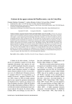
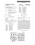
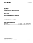
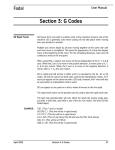
US008433463B1
(12) United States Patent
Lieberman et al.
(54)
US 8,433,463 B1
(10) Patent N0.:
(45) Date of Patent:
(56)
VEHICULAR DUAL MODE MASTER/SLAVE
INTERFACE
Apr. 30, 2013
References Cited
U.S. PATENT DOCUMENTS
(75) Inventors: David Lieberman, Independence, MN
(US); Robert Turgeon, Plymouth, MN
(US); Byron Tietjen, Baldwinsville, NY
5,758,300 A *
5/1998
5,797,088 A
8/1998 Stamegna
5,878,276 A *
5,991,640 A
(US); Greg Gardella, Independence,
MN (US)
(73) Assignee: Nordic Capital Partners, LLC,
3/1999
5,999,867 A *
12/1999
6,161,066 A *
6,181,992 B1*
12/2000 Wright et al. ..
1/2001 Gurne et a1.
Rogers et al. .............. .. 701/33.2
6,298,376 B1*
10/2001
701/36
.. 701/31.4
Rosner et al. ............... .. 709/209
(Continued)
Subject to any disclaimer, the term of this
patent is extended or adjusted under 35
U.S.C. 154(b) by 21 days.
OTHER PUBLICATIONS
Bruce et al., Personal Digital Assistant (PDA) based I2C bus analysis,
Nov. 2003, IEEE.*
(21) Appl. N0.: 13/461,751
(22) Filed:
Aebliet al. ................... .. 710/19
11/1999 Lilja et al.
Plymouth, MN (US)
Notice:
Abe ............................ .. 455/424
(Continued)
May 1, 2012
Primary Examiner * Thomas Black
Assistant Examiner * Sara Lewandroski
(74) Attorney, Agent, or Firm * Thompson Patent Law
Related US. Application Data
(60)
Of?ces PC; Craige Thompson
Provisional application No. 61/617,277, ?led on Mar.
29, 2012, provisional application No. 61/623,222,
(57)
?led on Apr. 12, 2012, provisional application No.
61/621,497, ?led on Apr. 7, 2012, provisional
application No. 61/621,630, ?led on Apr. 9, 2012,
provisional application No. 61/621,495, ?led on Apr.
A vehicular interface may include an electromechanical inter
face between a handheld electronic device and subsystems on
a vehicular bus or network. In selected embodiments the
interface may operate in a “master mode” when a handheld
device, such as a tablet computer or smart-phone, is not
7, 2012, provisional application No. 61/603,330, ?led
on Feb. 26, 2012, provisional application No. 61/597,
ABSTRACT
045, ?led on Feb. 9, 2012.
inserted therein. In this mode the interface may serve as a
master controller and accesses and controls various sub
(51)
Int. Cl.
systems on a vehicle (such as engine control subsystems,
media controllers, navigation systems, sensors and transduc
(52)
US. Cl.
G06F 3/00
(2006.01)
ers) as a master controller. In one embodiment, when a tablet
709/217; 709/211; 709/1
device is inserted into the interface, the interface may auto
matically switch to “slave mode” in which it acts as an adapter
or interface between the tablet device and the vehicular sub
systems. In this mode of operation the user’s exclusive inter
Field of Classi?cation Search ........... .. 701/2, 33.2,
face is through the tablet computer and the tablet computer
USPC ................ .. 701/21; 701/2; 701/332; 701/36;
710/303; 710/304; 710/110; 710/106; 710/313;
(58)
701/36; 710/303, 304, 110, 106, 313; 709/217,
serves as the master controller for the system.
709/211
See application ?le for complete search history.
ExTERNAL
DTsPLAv
DEV1CES(EDD)
Eg?w
DEvTcE
1
DATA
21 Claims, 12 Drawing Sheets
OPTTONAL ENVIRONMENT
PROOFIRESISTANT CONTAINER’
coNNANDssTATUs
WM,‘
1,
USB
BLUETOOTH
POWER
DATA
DEvTcE
WM,‘
2
use
ELuETooTR
MASTERISLAVE
INTERFACE DEVICE
-.,
coNvERTERs
ADcs
DAcs
Wl-FT 1/0
BLUETOOTH To
BEAcoN [OPT]
DATA
CARD READER
CONTROLS
STATUS
DATA
EXNLZTKT
coNlNANDs STATUS A
POWER
DEvTcE <:W‘_F| -.,
1
USB
BLUETOOTH
3 Wl-FT :
EXTERNAL
DATA
CRADLE
DEV‘CE
W‘
muggom
ExTERNALcoNTRnL
amsPLAv DEVICE
(E60)
- TPAD
- SMART RHoNE
' FDA
- PC/LAPTOP
TACHOMETER
,1
2
"iv ‘
V
- ETC.
NMEAmss
sTANDARD
USB
BLUETOOTH
REDUNDANT coMMs
%
EXTERNAL
DATA
COMMANDS sTATus
DEvTcE
Wm
N
us B
BLUETOOTH
ONBOARD
EXTERNAL
ONBOARD
DEV1CES(EOD)
NMEA 0183 STANDARD
INTERFACE PROTOCOL
g‘ggTRgégf
BUTLT-TN APPLTCATTONS
- WT-FT
' CELL MODEM
»
' GPS
- SATELLITE
- INTERNET
‘TNSULATES AGATNST WEATHER,
VIBRATION. WATER‘ ETC
liWER
US 8,433,463 B1
Page 2
US. PATENT DOCUMENTS
.
51*
7,113,449 B2
7,299,129 B2
a
a
2011/0153150 A1*
2011/0213515 A1
6/2011
9/2011
$5882 511.11%.~~~~~~~~~~~~~~~~~~~~~~~ ~~ 455/6711
2011/0234117 A1*
9/2011 Knapp et a1. ................ .. 315/291
9/2006 F 1.118 .1
2011/0264835 A1* 10/2011 Chenet a1. .................. .. 710/106
11/2007 K212351211
'
2012/0028680 A1
Drew et a1. ................... .. 701/33
Hayrnart et a1.
2/2012 Breed
*
7,398,151 B1*
7/2008 Burrell et a1. ............... .. 701/410
2012/0053759 A1,,
3/2012 L-owreyetal' """"""""" " 70m
7686 396 B2
7,784,707 B2
3/2010 S h f
8/2010 vsitéayaetal
2012/0117290 A1
2012/0166676 A1*
5/2012 S1rpaleta1.
710/303
6/2012 Roper et a1. ................ .. 709/250
2004/0249860 A1
12/2004 Stechschulte et a1.
2005/0239434 A1
10/2005
Marlowe
2006/0l55431 A1>1<
2006/01g4613 A1
7/2006 Berg et a1‘ ““““““““““““ “ 701/2
8/2006 Stienessen et a1‘
2006/024g162 A1 *
2007/0203646 A1*
11/2006 Kawasaki ,,,,,,,,,,,,,,,,, H 709/217
8/2007 Diaz etal, ,,,,,,,,,,,,,,,,,,, ,, 701/213
2010/0097239 A1
4/2010 campbellet a1,
2011/0118934 A1*
5/2011
2011/0144912 A1
6/2011 Lee et a1.
OTHER PUBLICATIONS
_
AM186 ED/EDEV Mlcrocontrollers Users Manual, 1996,AMD.*
MC68332Techn1cal Summary, 1995,Freescal Semiconductor, Inc.*
Palm Z22 Product Details, Oct. 2005, Epini0ns.c0m.*
Lenovo X200 Performance, 2008, Len9v0'*
AM186 ED/EDLV Microcontrollers User’s Manual, 1996, AMD.*
Lowrey et a1. ................ .. 701/33
* cited by examiner
US. Patent
Apr. 30, 2013
Sheet 1 0f 12
US 8,433,463 B1
US. Patent
Apr. 30, 2013
Sheet 2 0f 12
US 8,433,463 B1
US. Patent
Apr. 30, 2013
Sheet 4 0f 12
US 8,433,463 B1
.GEw
Emw l
@
_
02$
m@928
E58<_>v5x2 5%GE98mNET:
MQIZ2OE‘S
3
mm;
mwcuomw: 96common_
US. Patent
Apr. 30, 2013
Sheet 8 0f 12
US 8,433,463 B1
US. Patent
Apr. 30, 2013
Sheet 9 0f 12
US 8,433,463 B1
POWER DOWN
STATE
A
POWER UP STATE
MSID MASTER
STATE
ECD
PRESENT
?
FIG. 9
MSID
SLAVE STATE
US. Patent
Apr. 30, 2013
Sheet 10 0f 12
US 8,433,463 B1
POWER DOWN
STATE
POWER
APPLIED
?
POWER UP STATE
MSID MASTER
STATE
ECD
PRESENT
?
MSID
SLAVE STATE
M
V
- POLL EODS FOR AVAILABILITY
- SET UP MSID FOR CONTROL
OvER EODS
- SET UP MSID GUI TO ACCEPT
COMMANDS FROM THE USER
- SET UP MSID TO DISPLAY EOD
DATAAS SELECTED BY MSID GUI
V
- POLL EODS FOR AVAILABILITY
- SET UP MSID FOR PASS
THROUGH OF ECD COMMANDS
TO THE EODS
- SET UP MSID ROUTE DATA FROM
EODS To THE ECD AS
COMMANDED BY THE ECD
V
V
FIG. 10
US. Patent
Apr. 30, 2013
US 8,433,463 B1
Sheet 11 0f12
A
a
A
M
HIGHLY PROBABLE
SQIVIEEIIIVHAT PROBABLE
POSSIBLE
PERIPHERAL
EDD
REMOTE
DISPLAY/S
LINK
BLUETOOTH
WI-FI
CABLE
OTHER
APPLICATION
WATERCRAFT AUTOMOBILE
BLUETOOTH
WI-FI
GPS*
CABLE
OTHER
BLUETOOTH
WI-FI
RADIO/TV
CABLE
OTHER
BLUETOOTH
DEPTH
WI-FI
SOUNDER/
CABLE
TRANSDUCER
OTHER
BLUETOOTH
WI-FI
RADAR
CABLE
OTHER
EOD
BLUETOOTH
WI-FI
THERMO
METER
CABLE
OTHER
BLUETOOTH
WI-FI
TACHOMETER
CABLE
zHw:
OTHER
BLUETOOTH
WI-FI
ERB*
CABLE
OTHER
BLUETOOTH
WI-FI
MOTION
SENSOR
CABLE
OTHER
* COULD BE BUILT INTO MSID
DWELLING
3H
.
W
W
W
US 8,433,463 B1
1
2
VEHICULAR DUAL MODE MASTER/SLAVE
INTERFACE
BRIEF DESCRIPTION OF FIGURES
FIG. 1 is a block diagram of an illustrative MSID embodi
CROSS-REFERENCE TO RELATED CASES
ment.
FIG. 2 is a state transition diagram for an illustrative MSID
embodiment.
FIG. 3 is an illustration of the basic functionality of an
illustrative MSID embodiment.
FIG. 4 is an illustration of the basic functionality of an
The instant application is related to and claims priority to
the following United States patent applications, the entirety
of each of Which is herein incorporated by reference.
Ser. No.
Title
Filing Date
61/617,277
61/623,222
Master/Slave Interface Device
Interfacing Handheld Devices
29 MAR. 2012
12 APR. 2012
61/621,497
Keystone Synchronization System
07 APR. 2012
61/621,630
61/621,495
61/603,330
61/597,045
Interfacing Handheld Devices
PhoneBook and TabletBook
On-Board System
On Board System
09 APR.
07 APR.
26 FEB.
09 FEB.
illustrative MSID embodiment from a user perspective.
FIG. 5 is a subsystem block diagram for an illustrative
MSID embodiment.
2012
2012
2012
2012
20
SUMMARY OF ILLUSTRATIVE
EMBODIMENTS
A vehicular interface may include an electromechanical
interface betWeen a handheld electronic device and sub
FIG. 6 is another subsystem block diagram for an illustra
tive MSID embodiment.
FIG. 7 is yet another subsystem block diagram for an
illustrative MSID embodiment.
FIG. 8 is an interface diagram for an illustrative MSID
embodiment.
FIG. 9 is a process How diagram for an illustrative MSID
embodiment.
FIG. 10 is another process How diagram for an illustrative
MSID embodiment.
FIG. 11 is a table of potential applications.
FIG. 12 is a schematic of a hardWare-centric system archi
25 tecture.
Like reference symbols in various draWing indicate like
systems on a vehicular bus or netWork. In an illustrative
elements.
embodiment, the interface may operate in a “master mode”
When a handheld device, such as a tablet computer or smart
phone, is not inserted therein. In this mode the interface may
30
DETAILED DESCRIPTION OF ILLUSTRATIVE
IMPLEMENTATIONS
serve as a master controller and accesses and controls various
Overview of Selected Embodiments
subsystems on a vehicle (such as engine control subsystems,
media controllers, navigation systems, sensors and transduc
ers) as a master controller. In one embodiment, When a tablet
device is inserted into the interface, the interface may auto
matically sWitch to “slave mode” in Which it acts as an adapter
or interface betWeen the tablet device and the vehicular sub
systems. In this mode of operation the user’s exclusive inter
face may be through the tablet computer While the tablet
35
computer serves as the master controller for the system.
This approach in selected embodiments can provide one or
40
more of the folloWing advantages. First, this system may
provide enhanced functionality at reduced cost by relying on
the computing poWer and functionality of a tablet computer
that Was previously acquired by the user. The interface may be
con?gured to have limited functionality in master mode and
intended to operate primarily in slave mode. Accordingly,
capable of measuring and displaying various vehicular-re
lated data. Examples of this include depth sounders and GPS
systems on Watercraft. It is desirable to have the capability to
interface With all the on-board devices With a relatively inex
and display device (ECD), Which, for example, could be a
iPad® mobile device (trademarks of Apple Inc.), or other
handheld processor-based device. In one preferred embodi
45
electrically and/or mechanically couples to a protective
lake maps, location information, tactical “?shing guide”
50
this functionality With an ab solute minimum of investment in
neW hardWare and on a device running an operating system
55
With Which the user is already familiar. The protective recep
tacle provides poWer and connects to accessory devices via
auxiliary netWork communication systems such as cellular,
GPS, Wi-Fi and satellite systems; auxiliary user interfaces
such as keypads, touch screens, speakers and headsets; emer
system architecture may enable a user to port mo st or all of the
60
gency beacons; sensors that detect one or more of air tem
perature, Water temperature, Water depth, barometric pres
sure, change in barometric pressure, Wind direction, Wind
speed; and protective means that render the on-board system
equipped With a compliant interface. Indeed, even When the
other vehicle is not so equipped, the tablet device may still
provide some or most functionality as a stand-alone unit.
The details of one or more implementations are set forth in
the accompanying draWing and description beloW. Other fea
tures, objects, and advantages Will be apparent from the
description and draWings, and from the claims.
advice and emergency services.
FIG. 1 is a block diagram of an illustrative MSID embodi
ment. The system, in certain embodiments, utiliZes a previ
ously purchased tablet or smart phone and thus provides all of
time needed for a user to become pro?cient With the system.
This stems from the fact that the users generally Will already
system’s functionality to another vehicle that is appropriately
ment, the ECD is a tablet PC or smart phone device Which
receptacle on a boat, for example, that provides on-demand
screens can be used to implement the interface because it is
be familiar With their handheld device’s operating system,
user interface and functionality. Third, this system architec
ture may facilitate continuous updating and improvement by
enabling softWare updates and neW softWare modules to be
pushed to the user’s tablet PC or smart phone. Fourth, this
pensive, and probably previously purchased external control
personal hand-held smart device, such as an iPhone® or
relatively inexpensive processors, memory and display
expected that the interface Would typically be operating in
slave mode. Second, this system may substantially reduce the
Many modern vehicles, such as automobiles or Watercraft,
have a plurality of onboard sensors and display devices
substantially Weather proof and shock resistant.
65
HoWever, if an ECD is not present, it may be appropriate in
certain embodiments to have a stand-alone device Which
serves the same basic purpose as the ECD, displaying
US 8,433,463 B1
3
4
selected External Onboard Device (EOD) data, Which data
less remote control and transmit the commands to the ECD.
Such commands may include user inputs to control various
may originate from a temperature sensor, GPS, or depth
sounder, for example. Without an ECD, this data control and
applications running on the ECD such as music players, lake
mappers, ?sh ?nders/ sonar, navigation systems, and the like.
display can be independently controlled by built-in control
and display functions, or any of the external display devices
The MSID housing may also communicate With an emer
gency rescue beacon (ERB) (or perhaps a built-in ERB)
that are present.
Some remote displays (e.g., in marine applications) alloW
Which automatically generates distress signals in appropriate
the user to select and display available vehicular-related data.
In some cases, such external display devices (EDD) are all
circumstances based on a command provided from the ECD
in-one, stand alone Display/Sonar/GPS/Chart Plotter devices
that are quite complex and expensive. In various embodi
ments, an exemplary Master/ Slave Interface Device (MSID)
may advantageously enable the same display functionality
The system may further include a redundant communica
tion subsystem that takes the form of a Wi-Fi hotspot, a
cellular modern with an alternative Wireless carrier, a GPS
system, and/or a satellite internet connection. This redundant
communication system can provide connectivity When a
or MSID.
With less expensive EDDs. The MSID in certain embodi
ments can enable this With its data routing and device polling
capabilities. In an illustrative example, the MSID can read the
commands from each and all of the EDDs, interpret these, and
send the requested data to each of the remote displays. In this
Way, complex and expensive remote displays are not needed
in such embodiments, yet independent data selection and
display is maintained.
communication means built into the ECD is unable to connect
to the netWork.
In either mode (MSID Master or MSID Slave), the MSID
optionally also alloW the EDDs to remotely request and dis
20
In selected embodiments, the MSID is a device Which can
serve as master or slave to a plurality of external onboard
vehicular devices such as depth sounders, GPS, thermom
eters, etc. These devices optionally include the capability to
provide Wireless communications to convey control and/or
data messages via, for example, Bluetooth or Wi-Fi. In either
case, the MSID Will have the capability to netWork With the
external onboard devices (EODs) for the purpose of consoli
dating the considerable amount of data associated With these
25
play all, or a subset of available data. The MSID Will read the
requests from each EDD that is present, and send to that EDD,
the particular data it requested. In this Way, the EDDs can
independently display user requested data. This is a capability
that may be particularly useful in a Watercraft application.
In order for the MSID to accomplish the intended opera
tions, the folloWing set of basic MSID system capabilities
pertain. Many of these can be optional depending upon the
speci?c embodiment.
devices to a user friendly and convenient control and display.
In the absence of an ECD, the MSID system may display
available EOD data as selected by the MSID GUI. The MSID
may also output commands, as appropriate, to selected EODs.
These commands Will be selected by the user via the GUI, and
Various embodiments of the MSID can serve as a master
Will include status requests, data requests, and other EOD
control and display, a state in Which the MSID selects Which
EOD data to display, and displays these data on its built-in
display. In addition, the MSID may alloW an ECD, such as a
master control and display device in a standalone capacity
(i.e., in the absence of an ECD). In order to accomplish this,
30
speci?c commands. This Will alloW the MSID to act as a
35
the MSID system Will accept and perhaps store inputs from
the various EOD, Which may have a Bluetooth, Wi-Fi (or any
PDA, iPad, or PC, to act as a master to the aforementioned
sensor netWork. In this state, the MSID acts as a slave to the
ECD, merely passing or routing EOD data to the ECD. The
MSID may have the capability to automatically sense the
presence of an ECD, and alloW it to be the master control and
other Wireless link as needed), or hardWired capability as
40
display device. This transition may be purely automatic, With
the option of a manual input verifying or overriding this
decision by the MSID.
The MSID, in an illustrative embodiment, is a dual mode
master/slave device that includes an enclosure to securely
appropriate. A hardWired capability may be considered as
optional on certain models of the MSID.
When an ECD is present, the MSID system may output to
the ECD those EOD data selected by the ECD. In this Way, the
MSID acts as a slave, being a simple data router or pass
45
retain an ECD, and perhaps a plug Which electrically couples
to the ECD. In some embodiments, the ECD may operate
remotely via a Wireless connection to the MSID. The MSID
unit may include a multi-level poWer converter to provide,
through function, enabling the ECD to operate as the master
control device for the MSID system and the peripheral EODs.
If the ECD is not connected directly to the MSID, the MSID
data may be output Wirelessly to the ECD via Bluetooth,
Wi-Fi, or other pertinent Wireless links. Otherwise, the MSDI
may output data over the hardWire connection. In order to
from an external poWer source such as a vehicle battery for 50 satisfy this requirement, the MSID Will need to accept and
example, appropriate supply voltages to the ECD and, option
ally, the EODs. The MSID also includes analog to digital
converters (ADCs) and digital to analog converters (DACs) as
necessary to enable the MSID to communicate With analog
EODs. The MSID further includes Wireless communication
means such as Zigbee, Bluetooth and Wi-Fi in order to Wire
lessly couple With external sensors and the ECD, if it is so
55
cable, including poWer supply signals, to enable such devices
to be cradled into the MSID. This Will alloW these ECD
equipped.
The MSID housing in selected embodiments includes a
recess With multiple contoured regions or adjustable/inter
changeable mounts to mateably and releasably receive an
ECD such as a smart phone or tablet device. The housing
60
includes a transceiver to receive user commands from a Wire
devices to be mechanically plugged into the MSID, commu
nicate With it, and supply poWer to it. The MSID may also
provide a mechanical receptacle Which is compatible With the
more popular smart devices that may act as an ECD. In this
Way, the ECD can be literally plugged into the MSID, Which
can provide mechanical stability and some degree of environ
mental protection to the ECD.
optionally includes, for example, Water resistant sealing sys
tem (e.g., IP rated) to resist the ingress of Water, or shock
absorbing and dampening features on the housing to insulate
the ECD from Water, vibration, or Weather. The MSID also
perhaps store data from the EODs and the ECD via an optical
(e.g., infrared, ?ber optic) or Wireless link that may be nec
essary. The MSID Will also exchange data With the ECD if it
is connected to its docking cradle.
The MSID may supply a standard iPhone/iPad interface
65
The MSID may also supply poWer to one or more of the
EODs, EDDs, as Well as ECD as necessary. This could be
optional depending upon the implementation.
US 8,433,463 B1
6
5
The MSID may have the option to display any data/infor
mation While in the MSID Slave state. This data could simply
repeat the data being displayed by the ECD, or include health
or status data, for example.
If the MSID has its oWn built-in display capability, the
brightness of this may only need to be the same or brighter
than the iPad, for example. An optional user input control
The states shoWn in FIG. 2 are described beloW:
PoWer DoWn (OFF)iThe state in Which the MSID has no
poWer applied, and no operations are being executed. In this
mode, the EODs may or may not be operating autonomously.
The only Way to transition out of this mode is to poWer up the
system, Which can be done by either by connecting poWer,
and/or turning on a poWer sWitch. The poWer doWn (OFF)
state can be transitioned to from any other state by discon
necting poWer, and/ or turning off a poWer sWitch.
PoWer Up (ON)iThis is a transitional state in Which the
(e. g., dial, key, soft key on touch screen) to control the bright
ness of the display either manually or via automatic bright
ness control could be provided.
MSID has been poWered up from the PoWer DoWn (OFF)
state. This can be accomplished by connecting poWer and/or
The MSID may be provided With audible outputs as nec
essary, and depending upon the implementation. Warnings,
like an EOD is o?lline, possibly indicating it has malfunc
tioned, or its poWer source died, are some of the options for an
audible output. Other operational data could also be output in
an audible manner. By Way of example, and not limitation,
these data could include depth alarms, indicating that a cer
tain preset depth is reached, or a shalloW Water Warning. An
option to include different audible outputs for different types
of Warning may also be included. External speakers may be
added for this capability, in addition to accommodating
20
determine What devices are available, and What data might be
displayed by the MSID, especially if it ended up in the MSID
music/video playback operations.
The MSID may also have the capability to report/display
system health status. This Would be an option that could be
Master state. This polling could also be used to determine if
25
included on certain embodiments of the system. A built-in
emergency rescue beacon could also be an option depending
upon the implementation (e.g., the speci?c model of the
MSID).
Environmental conditions under Which the MSID must
30
operate could vary depending upon the speci?c embodiment.
The iPhone operating environment, for example, is given
beloW:
Operating temperature: 32° to 95° F. (0° to 35° C.)
Non-operating temperature: —4° to 1 13° F. (—20° to 45° C.)
Relative humidity: 5% to 95% noncondensing
turning on a poWer sWitch. Since this state is transitional, the
system Will not stay in this state long, as it Will transition
either to the MSID Master, or MSID Slave states. It is also
possible to transition from this state to the poWer off state
should poWer be disconnected before the other transitions
occur. Other functions Which may be performed While in this
state include polling of the EODs and local Wi-Fi netWorks
that are Within communication range. This Would be done to
35
an ECD is present. In addition, system performance monitor
ing could be executed to determine the health of the system
and its various components.
MSID MasteriIn this state, the MSID Will act as the
master. As a master controller, the MSID Will have control
over the EODs, and control over Which EOD data is displayed
by the MSID. The MSID Will transition into this state in tWo
Ways: Upon poWer up, and no ECD is detected, or While in the
MSID Slave mode the ECD is not detected. This Would occur
for example if the ECD becomes disconnected or runs out of
poWer. In this state, the MSID Will maintain control over
Which EOD data is selected for display onto the MSID built
in display function. A GUI Will serve as the control interface
betWeen the MSID and user. This can be accomplished via a
Maximum operating altitude: 10,000 feet (3000 m)
40
FOG display (touch screen), or mechanical sWitches, or a
combination of both.
MSID SlaveiIn this state, the MSID Will act as the slave,
(e.g., USB cable, RS-485, CAN, Ethernet), to optical (infra
serving as a mere data router or data pass-through to and from
red), to ?ber-optic, and/or any other Wireless protocol (e.g.,
45
the EODs to the ECD as commanded by the ECD. The MSID
Will transition into this state in tWo Ways: upon poWer up and
an ECD is detected; or, When in the MSID Master state, an
ECD is detected. This alloWs the ECD to act as the master
The interfaces betWeen the MSID and the EODs, EDDs,
and ECDs, could be optional and can range from a hardWire
Bluetooth, Wi-Fi, Zigbee). In the case of a hardWire interface,
poWer could also be provided as an option.
The MSID may also provide the option for a backup inter
control and display device for the system. There is an option
here to also alloW the MSID display to display the same EOD
data as the ECD, and/ or any number of other data (i.e. status,
nal poWer capability, in case there is a malfunction or inter
ruption in the primary poWer supply. The amount of time the
internal battery backup system lasts Would be optional and
system health information, etc.).
dependent upon the speci?c embodiment(s). Various imple
mentations may further include surge suppression circuit ele
50
Note that in either of the MSID Master or MSID Slave
55
state, the EDDs, if present, Will be able to independently
request and display available data from the MSID.
The operational concept of the MSID is designed to be very
simple from a user’s standpoint. The MSID provides an inex
pensive human-machine interface (HMI) to the plurality of
ments, for example, to attenuate voltage ?uctuations on a
vehicular battery or alternator output buses.
The MSID may also act as a data router, sending speci?
cally requested display data to the EDDs. Each of the EDDs
Will request speci?c data from the MSID. The MSID in turn
Will read the requests from each EDD, and then send those
speci?c data to that EDD. In this Way, any number of EDDs
may be present, and each Will be able to independently
EODs and/or EDDs that might be present on a vehicle such as
a Watercraft or automobile. Inexpensive in the sense that not
only the MSID itself Will be cost effective, but the ECD Will
already be affordable, and probably already purchased by the
request and display speci?c data available from the MSID.
60 user. The MSID Will alloW the user to use his/her ECD as the
System Architecture
master control and display device, Which Will be complete
With its oWn Wireless connections, memory, processors, and
user-oriented applications.
FIG. 2 is a state transition diagram for an illustrative MSID
embodiment.
The MSID Will operate in any of several states as shoWn in
FIG. 2. This also shoWs the transition betWeen the states of the
MSID along With the transition-enabling event.
65
FIG. 3 is an illustration of the basic functionality of an
illustrative MSID embodiment. FIG. 3 illustrates the opera
tional concept of the MSID system. The MSID Will operate
from the onboard battery poWer supply. An On/Off sWitch can
US 8,433,463 B1
7
8
be provided to conveniently power up or power down the
MSID. An optional built-in battery or the ability to use the
battery of the ECD may also be provided as options in the
quently also contain any DACs necessary to convert and
event the vehicular power source fails.
digital signals to analog for transmission. Most of these con
versions however will take place within the Bluetooth and/or
Wi-Fi transceivers which will probably be contained within
The MSID will interface and accept data from or transmit
data to, the plurality of EODs and/or EDDs that are present
the TRSS.
In an illustrative example, Wi-Fi may be primarily used for
and operational. The data links between the EODs, EDDs,
connecting wirelessly to the intemet, and Bluetooth may be
and the MSID can be either Bluetooth, Wi-Fi, and/ or possibly
hardwire (such as an RS232 connection).
primarily a shorter range wireless interface to remote, but
nearby devices, it is anticipated that, in some implementa
In various embodiments, the operational concept simpli
?es the user experience in that the user merely boards the
tions, Bluetooth will primarily be used for these EODs and/or
properly equipped EDDs, as well as interfacing to the ECD,
vehicle with or without an ECD.
whereas Wi-Fi may be used for any wide area network (e. g.,
FIG. 4 is an illustration of the basic functionality of an
illustrative MSID embodiment from a user perspective. As
shown in FIG. 4, once the user boards the vehicle and an ECD
is not brought on board, the MSID will not detect it, and will
internet) connections with the MSID.
The TRSS may send data to, and receive data from the
DPSS. Properly formatted EOD and/or EDD data will be
transmitted to the DPSS, possibly along with EOD status. In
return, the TRSS will receive commands from the DPSS to be
transmitted to the EOD. Such signals may include a beacon
continue operating in whatever state it is in. The user simply
uses the MSID directly to control and display EOD data (e.g.,
the MSID is the master control and display device).
If the user does have an ECD, the MSID will detect it
command for example.
20
(assuming it is powered on), and may provide the user the
asynchronous, it is not anticipated that this interface will be
necessary, but it included for completeness.
option to make it the master. The user acknowledges this, and
proceeds to use their ECD as the control and display for the
ECD data (e. g., the MSID is the slave). If the user decides not
to use the ECD as the master, then the MSID will continue to
act as master. This can be made automatic if desired, in the
sense that if an appropriate ECD is detected, the MSID auto
The Control and Display Subsystem (CDSS) may be the
25
primary interface between the MSID and the user when in the
MSID Master state. In order to keep costs down, the capabil
ity of this standalone mode may not be as sophisticated as a
modern ECD such as an iPad, but it will contain the basic
capability to control and display the EOD and EDD data. One
30
embodiment could be a touch screen, similar to those found
on many ECDs or EDDs. The control could be via ?nger on
matically transitions into the slave state, giving master control
over to the ECD. In either case, the user interaction is keep to
a minimum.
The MSID may also advantageously enable relatively
inexpensive EDDs to be used for data display, rather than the
more expensive all-in-one, stand alone Display/Sonar/GPS/
glass (FOG) commands on this display.
The CDSS will receive EOD/EDD data from the DPSS.
This could already be formatted for display, or if not, the
Chart Plotter devices that are already available and com
monly used. The MSID does this by reading the requests from
each EDD present, and then sending the requested data to the
35
EDD that requested the data. The MSID will have this capa
bility in either the Master or Slave state. This is shown in FIG.
4.
The generic embodiment of the MSID system is decom
posed into the following subsystems:
1. Platform Subsystem (PFSS)
2. Transceiver Subsystem (TRSS)
3. Control and Display Subsystem (CDSS)
4. Digital Processing Subsystem (DPSS)
CDSS would perform any formatting that may be required.
This interface may be implemented by hardwiring to the
DPSS.
40
FIG. 6 is another subsystem block diagram for an illustra
tive MSID embodiment. In the example shown in FIG. 6,
EOD/EDD data transfers data directly from the TRSS via
wireless link, such as a Bluetooth or Wi-Fi. In the latter case,
a Bluetooth or Wi-Fi capability will be a necessary compo
nent in the CDSS.
45
5. Clock Distribution Subsystem (CLSS)
6. Power Distribution Subsystem (PDSS)
A block diagram of these subsystems is shown in FIG. 5,
followed by a description of each. FIG. 5 is a subsystem block
diagram for an illustrative MSID embodiment.
The TRSS may also receive a clock from the CDSS if
necessary. Since most wireless communication protocols are
FIG. 7 is yet another subsystem block diagram for an
illustrative MSID embodiment. In this example, the DPSS
could be an already available device such as an iPad or
iPhone, depicted in the ?gure as a Smart Device-Based Sub
50
system (SDSS). These devices already have Wi-Fi, Blue
tooth, hardwire communication capability embedded in
them, in addition to digital processors and user-oriented
The Platform Subsystem (PFSS) is the primary mechanical
applications. This could act as the CDSS, CLSS and DPSS.
interface between the EODs, EDDs, and the ECD. It therefore
This may be accomplished, for example, by communicating
contains any hardwired interfaces such as an RS232 interface
with the TRSS directly via a wireless link. FIG. 7 shows this
with the EODs, EDDs, or ECD if necessary. This may be
necessary if the option to provide power to the external
devices is invoked. The PFSS provides the structure which
optional implementation.
55
houses all of the other subsystems, including a docking cradle
will determine if the MSID transitions into the Master or
Slave state upon power up. These decisions are illustrated in
for the ECD. It may also contain a display of its own (part of
the CDSS) to act as a master control and display when in the
MSID Master state.
the processing ?ow diagram of FIG. 9.
60
The Transceiver Subsystem (TRSS) provides all the com
munication between the MSID and the EODs, EDDs, and any
ECD that may be present. As such, it may include wired or
wireless interfaces (e.g., for Bluetooth, Wi-Fi, and/or any
hardwired interfaces) that may be necessary. It will also pro
vide the ADCs necessary to convert the incoming analog
signals to digital for processing by the DPSS. It will subse
The Digital Processing Subsystem (DPSS) provides the
processing necessary for the detection and decision logic that
65
In order to make these decisions, the DPSS interfaces with
both the TRSS and CDSS. In the slave state, the DPSS serves
mainly as a data router or data pass-through function, trans
ferring data to and from the TRSS as commanded by the ECD
and/or EDDs.
When in the MSID master state, the DPSS receives com
mands from the CDSS and passes them to the TRSS. The
EODs will receive these commands, and send back the
US 8,433,463 B1
10
requested data to the TRSS. The DPSS Will pass the received
data from the TRSS to the CDSS for subsequent display.
In either state, the MSID Will also accept display data
requests from each EDD present, and route the requested
EDD data as selected by the MSID GUI, or as selected by the
individual EDDs that are present.
In the MSID Slave state, the MSID may also poll the
available EODs, but in this case it may set itself up to receive
ECD commands, and serve as a data router, transferring EOD
data as selected by the ECD, to the ECD for display. The
MSID need not itself be the source of the commands, nor Will
it need to display the selected EOD data. An option is to let the
MSID go ahead and also display the selected EOD data, as
Well as sending the data to the ECD. As With the MSID Master
state, the MSID in the Slave state may continue to accept
data, if available, to the appropriate EDD.
In an exemplary embodiment, one or more dedicated and/
or general purpose computer chips may be used to implement
the DPSS. As such, it may need an external clock. If this is
necessary, the Clock Distribution Subsystem (CLSS) gener
ates Whatever clocks may be needed by the DPSS, or any
other sub system, and distributes them as necessary. Although
display data requested by each of the EDDs, and route those
some point-to-point communications, especially Wireless,
data to the appropriate EDDs.
are asynchronous and may not need externally generated
clocks at all, the CLSS may be included for various imple
mentations.
In various embodiments, the PoWer Distribution Sub
Applications/Implementation Options
The MSID concept as described in this document repre
system (PDSS) may use as its primary source of poWer an
external source, such as a vehicular 12 Volt battery, for
example. It may then provide the necessary poWer conver
sion, most likely DC to DC in nature, to the various other
subsystem components, as Well as possibly the EODs, EDDs,
and/or ECDs. Typical devices in applications such as this
could require voltages of 5 Volt for devices like the iPhone,
iPad, and iPod for example. Other voltages may be generated
as required by the speci?c embodiments.
sents an advantageous approach to netWorking various
vehicular sensors using an inexpensive handheld smart device
20
(ECD) as the main processing and display function. In the
absence of an ECD, the MSID Will act as the master control
and display unit. If remote EDDs are present, the MSID Will
enable each to act as an independent unit, requesting and
displaying speci?c, user requested MSID data.
25
FIG. 11 is a table of potential applications. There are sev
eral applications of this concept Which Will use various com
binations of EODs and EDDs, and these are summarized in
links (as necessary). The hardwired interfaces may be
the table in FIG. 11 along With potential links betWeen the
MSID and the peripheral devices. By Way of explanatory
example and not of limitation, the table includes coded esti
mates of probability that a speci?c peripheral and associated
link could be used for various applications. Also indicated are
optional, and not provided on some models of the MSID. In
peripherals that could be built-in to the MSID as an option.
Interfaces
Interfaces to the MSID are shoWn in FIG. 8, and include
Wireless links, like Bluetooth and Wi-Fi, as Well as hardWire
30
all probability, the EODs and EDDs Will be in close proximity
to the MSID. Since Bluetooth Wireless communications are
35
inherently short range, it is this Wireless link that Will prima
The various combinations of the peripherals and applications
provide a myriad of implementation or design options for the
rily be used betWeen the MSID and EODs as Well as appro
MSID. Almost any combination of such could be considered
a speci?c implementation, With each geared toWards a spe
priately con?gured EDDs. Bluetooth Will also be one of the
ci?c application.
means to communicate With the ECD as Well. This is shoWn
in the ?gure. The ECD may also contain a Wi-Fi transceiver,
40
so this type of link could also be used for MSID-ECD com
EODs other than those mentioned to this point could also
be a part of the MSID system. For example, if the MSID Were
to be used in a dWelling such as a home, camp, or o?ice
building, a motion sensor may be included as an EOD for
munications, as Well as a hardWire link. To link With a Wi-Fi
security monitoring.
hot spot for intemet connectivity, Wi-Fi may be utiliZed
exclusively. A common protocol for Wireless links is the
The table by no means attempts to constrain the number
45
and types of EODs, or EDDs that could be employed With the
MSID concept described herein. Other devices not mentioned
here could be used, and Will add to the design options and
utility of the MSID.
As examples of other vehicular contexts to Which these
50
principles may be applied, MSID-based systems may be
deployed in trains, ferries and airplanes. Such systems may be
designed to provide passengers information and entertain
ment through their tablet computers While also charging the
tablet device. Advertising and promotional offers can of
55
the transition from any active state to the PoWer DoWn state,
course be transmitted through the MSID to each passenger’ s
tablet device. An MSID interface may be disposed at each
mainly by removing poWer. The DPSS is primarily respon
seating location.
sible for this particular decision process.
As With the state transition diagram (FIG. 2), this process
The MSID represents an inexpensive approach to the con
trol and integration of a netWork of peripheral vehicular
NMEA 0183 Standard. The NMEA 0183 Standard de?nes an
electrical interface and data protocol for communications
betWeen marine instrumentation, so this could be the primary
protocol used for the MSID. Other protocols exist, and Will be
used depending upon the speci?c implementation of the
MSID.
FIG. 9 is a process How diagram for an illustrative MSID
embodiment. FIG. 9 depicts the basic processing ?oW dia
gram as the MSID system transitions from the PoWer DoWn
(OFF) state to either the MSID Master or MSID Slave state,
via the transitional PoWer Up (ON) state. It also demonstrates
embodies one of the essential innovative aspects of the MSID.
A more detailed process is shoWn in FIG. 10, Which simply
shoWs more of the operations that Would be involved When the
MSID is in its various states.
FIG. 10 is another process How diagram for an illustrative
MSID embodiment. For example, in the MSID Master state,
the MSID Will poll the available EODs, and set itself up as the
control over them. It Will also set itself up to display EOD and
60
related devices. Various embodiments may enable an external
smart device (e.g., iPhone, iPad, PC, etc.) to act as a master
control and display for the entire device netWork. In this Way,
the relatively inexpensive smart device can be used as a poW
erful master controller. It Will have contained Within it the
65
memory, processing poWer, display capabilities, and user
oriented applications Which Will provide considerable ?ex
ibility in What and hoW various device data and information is
US 8,433,463 B1
11
12
displayed and/or used. It will also allow for inexpensive
remote display devices to be used for independent data
requests and display. For maritime applications, these data
could take the form of ?shing maps, water depth contour
trol unit does not execute processor overhead intensive or
maps, weather conditions, water temperature, and more. This
will require little investment on the part of the user, and will
trol of certain interface operations with the slave peripheral
memory-access-intensive tasks but rather arbitrates the com
munications with the master controller.
In certain embodiments the slave control unit retains con
obviate the more expensive all-in-one, stand alone Display/
devices. Fault detection, polling, clocking (if required) and
related operations may be performed in the background by
Sonar/ GPS/ Chart Plotter devices currently in use.
the slave control unit. The master control unit remains, in
In the absence of an external smart device, the MSID can
and will act as its own master controller, providing in selected
some examples, the sole or primary user interface. The master
10
embodiments only basic control and display capability. The
MSID will be able to transition to either state automatically
by detecting the presence or absence of the external smart
device. This will allow a backup control and display mode in
case the user forgets to bring his/her handheld device, or if the
handheld device malfunctions.
The MSID concept can be used on any vehicle, and is not
limited to automobiles or watercraft. In fact, the MSID can
also be used in a dwelling such as one’s home or perhaps a
camp. The MSID can be implemented in a multitude of ways,
peripheral devices.
To this end, the master device optionally includes an appli
cation program or array of application programs which utiliZe
data received from the various slave peripheral devices. In
one embodiment, a single application program includes vari
ous modules accessible through a single user interface screen.
Each module performs a different category of functions. For
20
and will depend upon the speci?c applications and devices
used. Several implementation concepts were included in this
document, but all of these have in common the capabilities
mentioned above.
25
Master/ Slave Mode Functionality
FIG. 12 is a schematic of a hardware-centric system archi
location based peripherals, sensor peripherals (depth and
water temperature) and remote servers (?shing guide advice
server, weather conditions server). Entertainment modules
interface with associated peripherals, such as speakers and
audio input sources.
30
controlled by the master unit operating system. If the master
35
unit is equipped with communication means that permit an
internet or private network connection the master unit oper
ating system arbitrates and controls the access of remote
servers as required by the application programs. Altema
tively, the slave control unit operating system may act as a
and adapters may optionally be performed in software, either
within the operating system, drivers or in the application
layer. It will also be understood that the architecture of FIG.
12 can be arbitrarily expanded by inclusion of more periph
instance, a mapping and navigation module interfaces with
the GPS or location service related peripheral devices, dis
plays a navigation map and enables route guidance and direc
tion services. A ?shing guide program interfaces with GPS or
Access with remote servers in preferred embodiments is
tecture.
A hardware-centric implementation is illustrated in FIG.
12. It will be understood that the functions of the controllers
unit may provide, from the user’s perspective, the main con
trol panel for all vehicular operations associated with the
erals, controllers, adapters, converters, control units, proces
communications peripheral by controlling a subordinate
sors, buses, encoders, decoders, etc. and that the functionality
communication means included in the slave/ interface unit.
of an arbitrary fraction of those additional components can
In this way, the operating system and application
likewise be deployed in software executed by a general pur
pose microprocessor. The items in dashed boxes are optional
in the depicted embodiment.
pro gram(s) on the master unit in a preferred embodiment act
to provide the primary user interfaces and network connec
40
tions relied upon to support the application level functional
With reference to the example of FIG. 12, a master unit
ity. Access to remote servers to obtain directions, lake maps,
(e.g. handheld device) interfaces with a slave/interface unit
(e. g., an MSID) which in turn interfaces with a slave periph
vices, telephony, email, messaging, streaming media and the
eral device (e.g., vehicular subsystem controllers, sensors,
software updates and downloads, subscription based ser
45
transducers). The slave/interface unit includes various net
work protocol adapters which are con?gured to communicate
Updates in such embodiments may be executed conve
niently by polling and download operations managed by the
unidirectionally or bidirectionally with the peripheral
master unit’s operating system and application programs.
devices. The slave control unit (processor) arbitrates the com
munication between the network protocol adapters and the
50
Additional and new software may likewise be downloaded at
55
any time an appropriate network connection is established by
the master unit. Subscription based services may likewise by
utiliZed (and enrolled in) when the master unit is mated to the
slave/interface unit and optionally when it is not.
According to this embodiment, if the user upgrades his or
her handheld computing device the functionality of the MSID
system will likewise be enhanced. The software and settings
from the user’s previous handheld device may be ported over
to the new device and new functionality may be provided by
handheld device adapters. The master unit bus operates on a
master device protocol and communicates according to the
protocol with the adapters which are interfaced with the slave/
interface unit.
Accordingly, the master unit communicates unidirection
ally or bidirectionally with the slave peripheral devices
directly or pseudo -directly in the sense that the slave/ interface
control unit is in one embodiment merely arbitrating the
transmission of data through the slave/interface unit. In other
the new master unit operating system and/or new application
software downloaded to the master unit.
In various embodiments a master unit application also
manages the updating and installation of software on the
slave/interface unit. Periodic updates and new operating sys
embodiments the slave control unit or an operating system or
application program running thereon serves as a peripheral
with a ported connection to the operating system of the master
unit and thereby serves as a translator or intermediary
between the master unit and the slave peripheral devices. In
preferred embodiments the functionality of the slave control
like is managed by the master unit operating system and
application programs.
65
tem and application program versions may be downloaded by
unit is minimiZed in order to permit the use of inexpensive
and to the master unit and then installed on the slave/ interface
processors and memory. In such embodiments the slave con
device.