1
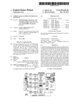
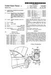
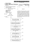
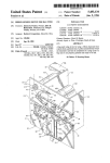
US006212449B1
(12) United States Patent
(10) Patent N0.:
(45) Date of Patent:
Wellman et al.
US 6,212,449 B1
Apr. 3, 2001
OTHER PUBLICATIONS
(54) DIAGNOSING MALFUNCTIONS IN
MATERIALS HANDLING VEHICLES
Raymond, EASi Reach Service Manual, Jan. 15, 1995, pp.
47—49 menu description; p. 73 trouble shooting a problem:
Code 2A; and, pp. 53—55 total available trouble codes.
(75) Inventors: Timothy A. Wellman, ColdWater;
James W. Gaskell, Troy; Donald T.
Meiring, Osgood, all of OH (US)
* cited by examiner
(73) Assignee: Crown Equipment Corporation, New
Bremen, OH (US)
(*)
Notice:
Primary Examiner—Tan Nguyen
Subject to any disclaimer, the term of this
patent is extended or adjusted under 35
U.S.C. 154(b) by 0 days.
(74) Attorney, Agent, or Firm—King & Schickli PLLC
(57)
ABSTRACT
A diagnosis system for materials handling vehicles leads
service personnel step-by-step through diagnosis and repair
of faults Within the vehicle. Faults are assigned correspond
(21) Appl. No.: 09/161,823
ing event codes so that When a fault is detected, its corre
(22) Filed:
sponding event code is displayed. The event codes uniquely
identify systems of the vehicle in Which faults have occurred
by having the event codes for a given vehicle system all start
Sep. 28, 1998
Related US. Application Data
(60)
Provisional application No. 60/060,487, ?led on Sep. 30,
1997.
(51)
Int. Cl.7 ............................. .. B66F 9/24; G01R 31/00
(52)
US. Cl. ............................................... .. 701/29; 701/35
(58)
Field of Search ................................ .. 701/29, 30, 32,
701/33, 34, 35; 340/438, 439
(56)
References Cited
2/1996
Shirane et al. ....................... .. 701/35
5,528,496 *
6/1996 Brauer et al.
5,539,869 *
7/1996 Spoto et al. ..
5,541,840 *
7/1996
5,579,227
Gurne et al. ..
0 416 171 A2
0 468 805 A2
.. 701/29
395/154
.. 701/29
11/1996 Simmons, Jr. et al. ............. .. 701/29
FOREIGN PATENT DOCUMENTS
portion of the vehicle Wherein the malfunction has occurred,
the components Which caused the malfunction and,
preferably, provides a pictogram of that portion of the
vehicle. The technician advances to the malfunctioning
portion of the vehicle Where another pictorial depiction of
the components of that portion of the vehicle assists in
locating the components. All components are marked Within
the vehicle by identi?ers Which are consistently used
throughout the diagnostic information, pictorial representa
U.S. PATENT DOCUMENTS
5,491,631 *
With the same number. Thus, the technician knoWs from the
event code What system needs to be diagnosed/repaired and
What tools and probable parts Will be needed. The event code
is used to access diagnosis information identifying the
tions and service manuals. The diagnostic information tells
the technician What to do to diagnose the components With
the diagnosis being preformed using the electronic control
system of the vehicle to monitor inputs to and outputs from
the electronic control system and to apply limited duration
full poWer test signals to components to be tested. The
diagnostic information is con?gured so that testing is done
from the end of control paths back to the controller.
3/1991 (EP) .
1/1992 (EP) .
22 Claims, 15 Drawing Sheets
RRSOOO
[15mm SYSTEM
300
340
OUTPUTS
U.S. Patent
Apr. 3, 2001
Sheet 1 0f 15
US 6,212,449 B1
FIG. 1
\ \
x__\
J90
\
Q
4'
. .
J
$75
/§/
70 _->
I40
/
no
85
,v-
\m
i
125
i,» Ma?a‘
Vii/
_
I35
"
z’
.
‘O f
.- ‘
40/
I
I20
.
_
’
‘ '
46
I30
44
I22
' I I 42
55
60
I5
50
U.S. Patent
200 /
Apr. 3, 2001
Sheet 2 0f 15
US 6,212,449 B1
L 225
U.S. Patent
Apr. 3, 2001
55
25 0 S25 E2
Sheet 5 0f 15
8h
5:
5 3 £5
w,
r
o¢m.\
0m
w
Pz<o
NB’
i\Em
US 6,212,449 B1
U.S. Patent
Apr. 3, 2001
0mm
3%
jjjjjiiiiij
1111111111
J
uvdl
Sheet 6 0f 15
US 6,212,449 B1
U.S. Patent
Apr. 3, 2001
US 6,212,449 B1
Sheet 8 0f 15
FIG.5
DEID E!
A ‘ANALYZER
“GD
C
CALIBRATE
F
FEATURES
PREVIOUS MENU OR
INCREASE COUNT
220
H HOUR RESET
NEXT MENU OR
DECREASE COUNT
L LOC EVENTS
225 \ :
ENTER MENU OR
ACCEPT INPUT
P PREFORMANCE
U
UTILITIES
U.S. Patent
Apr. 3, 2001
Sheet 11 0f 15
US 6,212,449 B1
h
I25 .2:;.
u
mdw
o0$5528am
o: \
_
Q
.0
O
OQO
O %
w
omm
5:52
0W9
.m.was‘. .
aO
0
.
n
m.
.v.
“m:
is?
N. an.
@wQ6Em2cwoaEu2é
/
,,5225so
£5:E,
.w/
.0J09o8
U.S. Patent
Apr. 3, 2001
Sheet 12 0f 15
2E25: 25:5we”
“13% 5 2 E5%:
>
.515.%.
"1is=2$2.5;1m,i
07:2:2;E
.
,
3
2
5
;
.
2
E
,
/
.f,
Z02
i
$
55
2
3
G5
.
6EQHm:3c25oq0Eou
5.,E;as:$am5 2
2E;25%22a..
2:E;2
m.0_n
2a:?52
US 6,212,449 B1
U.S. Patent
Apr. 3, 2001
$5$8:.55
@WQc5Jo62Wa;QS
9. K
Sheet 13 0f 15
E
2
5
2
5
8
%
;
5280m5: 2%:
85$8::5
US 6,212,449 B1
2:.065:
2E.52?:
U.S. Patent
Apr. 3, 2001
Sheet 15 0f 15
US 6,212,449 B1
F I G. 12
smus cone
POT2 (RAISE/LOWER)
ABOVE ELECTRICAL LIMIT
STEP 1i
TURN KEY ON WHILE PRESSINC THE @ BUTTON.
SELECT POT2 IAZAI ON DISPLAY MENU.
MOVE CONTROL HANDLE TO CONFIRM THE FOLLOWING
READINGS.
IFI APPROXIMATELY 5 VOLTS. OPEN IN CIRCUIT
BETWEEN POTENTIOMETER AND CA405-16
OR CA405-8 ON ACCESS 2.
OKAY, REPLACE POTENTIOMETER.
IFI APPROXIMATELY 2.5 VOLTS RAISE/LOWER HANDLE
IS IN CENTER POSITION. CORRECT READING
IFI APPROXIMATELY L2 VOLTS RAISE/LOWER HANDLE
IS IN FULL UP POSITION. CORRECT READIN
IF: APPROXIMATELY 3.8 VOLTS RAISE/LOWER HANDLE
IS IN FULL LOWER POSITION. CORRECT READING
CORRECT READINGS CONFIRMED, INTERMITTENT
CONNECTION LIIIELY IN POTENTIOMETER CIRCUIT
THEN CHECK CONNECTIONS AND POTENTIOMETER
NOTE: ADJUST AND CALIBRATE THE POTENTIOMETER
AFTER REPAIR.
MULTI -TASK CONTROL
ACCESS 2
:0 CA405 ~16
US 6,212,449 B1
1
2
DIAGNOSING MALFUNCTIONS IN
MATERIALS HANDLING VEHICLES
properly functioning components. Preferably, such an
CROSS-REFERENCE TO RELATED
APPLICATIONS
corrected With the procedure not only leading the repair
person to faulty components but clearly indicating the
improved diagnostic arrangement Would folloW a set pro
cedure regardless of the location of faults Which need to be
identity and location of those components on the vehicle
This application claims the bene?t of US. Provisional
through directions, maps and component identi?cation
labeling. In addition, the directions, maps and component
Application Number 60/060,487, ?led Sep. 30, 1997, Which
is incorporated herein by reference.
BACKGROUND OF THE INVENTION
10
provided to the service person on-time, rather than being
The present invention relates in general to materials
handling vehicles and, more particularly, to diagnosing and
repairing such vehicles. While the present invention is
generally applicable to materials handling vehicles, it Will be
described herein With reference to a rider reach fork lift truck
presented as a mass of information Which can overWhelm,
frustrate and delay diagnosis and repair.
15
SUMMARY OF THE INVENTION
This need is met by the invention of the present applica
tion Wherein a diagnosis system leads service personnel
for Which it is particularly applicable and for Which it is
initially being utiliZed.
Materials handling vehicle repairs and service have con
ventionally been handled by trained personnel Who are
familiar With vehicles in need of diagnosis and repair.
identi?cation labels should be provided to the service person
as needed in the diagnostic process, i.e., information is
step-by-step through diagnosis and repair of faults Which
might occur in a materials handling vehicle. Possible faults
20
Within a vehicle are assigned to status or event codes Which
Control systems in these vehicles may generate an event
correspond one-to-one With the faults. Accordingly, When a
code prior to being shut doWn to prevent possible damage to
fault is detected, its corresponding event code is generated
the vehicle due to a fault. Trained repair personnel Were then
faced With a dead vehicle With no information regarding the
fault or, at best, Were provided With an event code Which
identi?ed the general area of the vehicle Wherein a fault had
and displayed to the operator of the vehicle as Well as being
stored in a history of logged events.
25
The event codes uniquely identify systems of the vehicle
in Which faults have occurred by having the event codes for
occurred. Armed With this knoWledge of the vehicle, and
a given vehicle system all start With the same number, e.g.,
possibly the general direction provided by conventional
ZXX codes indicate faults in the hydraulic system of the
vehicle, 3XX codes indicate faults in the traction/braking
system of the vehicle. Thus, from the event code alone the
operator knoWs What system Will need to be diagnosed/
repaired, What tools and probable parts Will be needed. The
event codes, the repair personnel Would make reference to a
detailed service manual to repair the faults.
While some repair personnel are very highly skilled and
are able to quickly diagnose and repair faults in material
30
handling vehicles under these circumstances, many other
event code is then used to access diagnosis information
less skilled and less experienced repair persons are not.
Repair persons of all skill levels can become extremely
frustrated When faced With little, if any, clue as to a potential
fault and a vast amount of general information about the
Which more speci?cally indicates the portion of the vehicle
Wherein the malfunction has occurred, the components
35
Which caused the fault and, preferably, provides a pictorial
depiction of that portion of the vehicle to familiariZe the
technician With the locations and identi?cations of the
vehicle Which contains a solution to the fault but no Way to
effectively identify that solution. What has been experienced
40
may be referred to as “sWaptronics”, i.e., sWitching out
components until a fault component, if any, is ?nally
replaced to return the vehicle to service.
When sWaptronics is employed, particularly in modern
components.
The technician then advances to the portion of the vehicle
containing the fault and opens that portion of the vehicle to
in the ?eld in response to such frustration is resort to What
display another pictorial depiction of the components of that
portion of the vehicle. All components are marked Within the
45
vehicle by identi?ers Which are consistently used throughout
materials handling vehicles Which include one or more
the diagnostic information, pictorial representations and
computers or “black boxes”, all too commonly a computer,
probably one of the more expensive system components, is
?rst replaced to be sure that it is not the cause of the fault
since historically it Was the most dif?cult to diagnose. If not
service manuals to reduce confusion and facilitate location
of components, diagnosis and repair of the components.
50
the problem, additional components also end up being
replaced resulting in large quantities of fault free compo
nents being replaced, possibly under Warranty, With resultant
costs and lost time both for the service person and the doWn
time of the vehicle. In addition to the high relative cost of
computer components, replacement of a computer is often a
more dif?cult task than replacement of components driven
by the computer Which components have proven much more
likely to be the cause of a fault than the computer.
Accordingly, there is a need for an improved arrangement
for diagnosing and repairing faults Which occur in materials
handling vehicles. Such an improved diagnostic arrange
ment should make diagnosis and repair less dependent on
the experience and skill level of a repair person by leading
the repair person step-by-step through a diagnostics proce
dure to accurately identify the cause of a fault and enable the
repair person to make a repair Without replacement of
The diagnostic information then tells the technician What
to do to diagnose the components to determine Whether they
are faulty and must be replaced or Whether the components
are functioning properly. The diagnosis is preformed using
the electronic control system of the vehicle With the tech
nician being able to con?gure the electronic control system
55
60
of the vehicle to monitor inputs to and outputs from the
electronic control system and to apply limited duration full
poWer test signals to components to be tested. The electronic
control system inputs and outputs can be monitored While
operating the vehicle in a normal manner. But When limited
time duration, full poWer tests are performed, normal vehicle
operation is inhibited.
The diagnostic information is con?gured so that testing is
done from the end of control paths back to the controller, i.e.,
controlled or signal generating components such as
65
solenoids, relays, sWitches, potentiometers and the like are
?rst tested to ensure that they are not faulty; next, circuitry
interconnecting those components to the electronic control
US 6,212,449 B1
3
4
system is tested; and, ?nally if no faults are found in the
peripheral elements of the system, modules of the electronic
control system are suspect in causing faults.
It is, thus, an object of the present invention to provide an
corner of the poWer unit 15 and to hydraulic motors, see
pump motors P1 and P2 of FIGS. 4 and 4D, Which supply
poWer to several different systems Within the truck 10.
Attached to the motor 42 is a brake 44 and a tachometer 46.
A caster Wheel 55 is mounted at the right rear corner of the
improved diagnostic system for a materials handling vehicle
Which guides service technicians step-by-step through the
diagnostic procedures to remove frustration from the diag
nostic process; to provide an improved diagnostic system for
poWer unit 15. A pair of outriggers 60 support the front end
of the truck 10.
Amast assembly 70, mounted to the front of the truck 10,
includes an overhead guard 75. Apair of forks 80 are carried
a materials handling vehicle Wherein an electronic control
system of the vehicle is used to monitor inputs to and outputs
from the control system for diagnosing faults; to provide an
improved diagnostic system for a materials handling vehicle
10
extendable mast elements 90. The fork carriage mechanism
85 may include a reach mechanism to alloW the forks 80 to
Wherein an electronic control system for the vehicle is used
to provide limited time, full poWer test signals for compo
nents suspected of causing a malfunction Within the vehicle;
and, to provide an improved diagnostic system for a mate
rials handling vehicle Wherein service technicians are guided
15
step-by-step through a diagnosis procedure Which initially
diagnoses and tests components Which are at the end of
control loops extending from an electronic control system,
then circuitry interconnecting those components to the con
be extended forWard of the mast assembly 70, a side shift
mechanism to permit the forks 80 to be moved from side to
side relative to the mast assembly 70, and a tilt mechanism
to permit the forks 80 to be tilted relative to the horiZontal.
As shoWn in FIG. 2, in the operator’s compartment 20 are
mounted a steering tiller 100 for controlling the direction of
travel of the truck 10 and a control handle 110 for controlling
the travel speed and direction of the truck 10 as Well as fork
height, fork extension, fork tilt and fork side-shift. Also
trol system and, ?nally, if all else is Without fault, examining
the control system itself.
Other objects and advantages of the invention Will be
apparent from the folloWing description, the accompanying
draWings and the appended claims.
on a fork carriage mechanism 85 Which is carried on
25
located Within the operator’s compartment 20 is a seat
assembly 120 Which is attached to the right side 122 of the
poWer unit 15, as shoWn. The seat assembly includes a back
rest 125, a seat 130, and a shelf 135. The seat assembly is
vertically adjustable for operator comfort. An armrest 140 is
also supported on the seat assembly 120 for movement
BRIEF DESCRIPTION OF THE DRAWINGS
thereWith. The control handle 110 is mounted on an arm 145
FIG. 1 is a perspective vieW shoWing a fork lift truck
incorporating the present invention;
FIG. 2 is a perspective vieW of the poWer unit of the fork
lift truck of FIG. 1;
FIG. 3 illustrates a display panel on the fork lift truck of
35
FIG. 1;
FIGS. 4 and 4A—4D are electrical system block diagrams,
With FIG. 4E shoWing hoW FIGS. 4A—4D ?t together to
form the electrical system block diagram of FIG. 4;
160 provides the operator With information regarding the
status of the battery voltage and may provide additional
information regarding and the fork height and the Weight of
the load on the forks 80.
FIG. 3 is a vieW of a display panel 170 on the electric
FIG. 5 is a diagram illustrating the second level menu
entries of the operating modes for the diagnosis system of
poWered lift truck shoWing various indicators for use by the
operator. On the display panel is a battery voltage level
indicator 175 (a type of fuel gauge). A symbol 176 repre
the present application;
FIG. 6 illustrates the second and third level menu entries
sents a discharged battery While a symbol 177 represents a
for the analyZer mode of operation of the seven layers of the
service menu shoWn in FIG. 5;
FIG. 7 is a pictogram of a contactor panel component and
extending from the armrest 140.
On the ?oor of the operator’s compartment 20 are tWo
pedals 150 and 155. The left-hand pedal 150 operates an
electric sWitch to control braking of the truck 10 While the
right-hand pedal 155 operates a sWitch indicating the pres
ence of the operator’s foot thereon. An operator’s console
45
charged battery. Indicator lamps 180 shoW the state of
charge of a battery 320, see FIG. 4.
A lift truck is represented by a draWing 190, above Which
are several lamps; namely, height Zone indicator lamps
C1—C4, Which indicate the height to Which the forks 80 of
Wiring map for use in the present invention;
FIG. 8 is a pictogram of a poWer component and Wiring
map for use in the present invention;
FIG. 9 is a pictogram of a control component and Wiring
map for use in the invention of the present application;
the lift truck 10 are recommended to be raised for a given
actual load on the forks 80, and fork height lamps H1—H4
and 80H, Which represent the actual height of the forks 80.
FIG. 10 is a pictogram of a traction motor map for use in
Also on the panel 170 are an operator correctable error
the present invention;
indicator 192 (an ISO standard symbol), a maintenance
FIG. 11 is a pictogram of a pump motors map for use in 55 needed indicator 194, a performance tune pushbutton 196, a
the present invention; and
truck hour usage pushbutton 198 represented by a styliZed
hourglass symbol, a maintenance pushbutton 200, a text
display screen 210, and three pushbuttons 215, 220 and 225
for controlling input of data using the text display screen
210.
In accordance With the invention of the present
application, diagnosing faults Within a materials handling
vehicle is performed using a system referred to as the
“Access 1-2-3”, Which is a trademark of CroWn Equipment
FIG. 12 is diagnostic information for an exemplary event
or status code 245.
DETAILED DESCRIPTION OF THE
INVENTION
FIGS. 1 and 2 shoW a rider reach truck 10 that includes
a poWer unit 15 Which includes an operator’s compartment
20, a battery compartment 30, and a motor compartment 40.
A battery in the battery compartment 30 supplies poWer to
a traction motor 42 located in the motor compartment 40 and
connected to a steerable Wheel 50 located at the left rear
65
Corporation, diagnosis system Which is a total diagnostic
solution that makes diagnosing a fault or failure on a vehicle
as easy as folloWing three simple steps, e.g., 1-2-3. The
US 6,212,449 B1
5
6
approach is straight forward, With each step being of man
ageable size and With the steps being consistently followed
for all faults to be diagnosed thereby eliminating uncertainty
5 are all represented by alphabetic characters Which can be
displayed on a seven-segment display: A—AnalyZer Mode;
C—Calibrate Mode; F—Features Mode; H—Hour Reset
Mode; L—IJog Events Mode; P—Performance Mode; and,
for the service technician and the resulting frustration. In this
Way, the Access 1-2-3 diagnosis system can be easily
utiliZed, regardless of the level of skill of a service
technician, to level the playing ?eld, or more accurately,
U—Utilities Mode.
Service technicians for materials handling vehicles have
level the diagnosing ?eld, for technicians.
The Access 1-2-3 diagnosis system deals With an elec
tronic control system 300 for the truck 10 as shoWn in FIG.
10
different skill levels due to experience, training and innate
abilities. Thus, the skill range of service technicians is from
highly experienced technicians Who can readily and system
atically Work their Way through a problem to technicians
With little or no experience Who have more difficulty in
4, menus available on the text display screen 210, or a
simpli?ed text display screen 210A, and hoW information is
solving diagnosis and repair problems. The goal of the
presented to the service technician in a timely or on time
Access 1-2-3 diagnosis system is to close the gap betWeen
these tWo extremes. That is, the Access 1-2-3 diagnosis
system is designed to provide a consistent trouble shooting
approach that substantially takes skill level out of the
informational approach to remove frustration from the diag
nosis procedure. The Access 1-2-3 diagnosis system directs
15
the service technician quickly to identify What circuit of a
given system is involved and hoW to diagnose it.
equation and produces a consistent approach to diagnosing
The electronic control system 300 of FIG. 4 includes three
modules, Access 3 module 340, Access 2 module 350 and
Access 1 module 360, each of the modules 340, 350, 360
having a microprocessor therein. HoWever, in the illustrated
embodiment, the Access 3 module 340 is the primary control
module and includes the softWare necessary and processing
for the proper operation of the truck 10 While the Access 2
problems.
To simplify the Access 1-2-3 diagnostic system, event
codes, Which identify faults Which are detected in the truck
10, correspond to the modules of the electronic control
system 300 of FIG. 4. Thus, any event code that starts With
a 3, i.e., an event code in the 300 series of event codes,
pertains to one or more components under the control of the
module 350 and the Access 1 module 360 serve primarily as 25 Access 3 module 340; and, any event code that starts With
intelligent I/O devices. Accordingly, the Access 2 module
a 2, i.e., an event code in the 200 series of event codes,
pertains to the Access 2 module 350. There are no event
350 is driven by the Access 3 module 340 during normal
operation and during operation of the Access 1-2-3 diagnosis
codes Which begin With a 1, i.e., in the 100’s, since the
system of the present invention. Of course, other electronic
control systems can include independent control modules
Access 1 module 360 or 365 is substantially self contained
Which Would operate autonomously When implementing the
Access 1-2-3 diagnosis system. The voltage of the battery
320 is converted to digital form by an analog-to-digital
tive to the operation of the truck 10.
Accordingly, When an event code is generated in response
converter in the Access 3 module 340 so that the micropro
cessor of the Access 3 module 340 knoWs the voltage level
technician Who is advised of the fault immediately knoWs
the system of the truck 10 Within Which the fault occurred.
That is, for event codes in the 200 series of codes, the fault
and concerned primarily With displaying information rela
to a fault detected Within the truck 10, the operator or service
35
of the battery 320. Also, every major current consuming
device in the truck 10 (except for pump motor P2) includes
is related to the Access 2 module 350 and hence to the
a current sensor Which provides current consumption data to
hydraulic system of the truck 10. Similarly, for event codes
the microprocessor of the Access 3 module 340.
The Access 3 module 340 also includes I/O devices
relating primarily to the traction and braking functions of the
truck such that the Access 3 module 340 corresponds to
traction/braking systems of the truck 10. The Access 2
module 350 includes I/O devices relating primarily to the
hydraulic functions of the truck 10 such that the Access 2
module 350 corresponds to the hydraulic system of the truck
10. The Access 1 module 360 includes an enhanced display
in the 300 series of codes, the fault is related to the Access
3 module 340 and hence to the traction/braking system of the
truck. Since the traction and braking are handled by the same
module in the illustrated embodiment of the present
invention, traction and braking are considered a single
system. HoWever, traction and braking could be separated
45
of I/O devices relating to the operator input and display
and controlled by separate modules of the electronic control
system, if desired, in Which case the traction and braking
systems Would have codes in different hundred series Which
Would corresponded to the tWo systems. Thus, for the
service technician there is a simple tie-in of the event codes
functions of the truck 10 as described above relative to FIG.
3. Also shoWn in FIG. 4 is an Access 1 module 365 Which
includes a standard display With the standard display being
With the truck systems to be diagnosed and repaired. Such
coordination facilitates and expedites repairs since When a
an abbreviated version of the display 170 of FIG. 3. Either
the Access 1 module 360 or the Access 1 module 365 Would
be used, but not both, on a single truck.
ing a fault code of XXX, the technician immediately knoWs
What tools and probable parts Will be necessary for the
In the standard display of the Access 1 module 365,
simpli?cations include removal of a number of elements
service technician is told that a disabled truck Was display
55
series of event codes or tools for the repair of the traction/
braking system for 300 series of event codes. The service
technician can then assemble the appropriate tools before the
Which are apparent by comparing the tWo displays in FIG.
4 or FIGS. 4C and 4D. In addition, the text display screen
210A is reduced from the full feature display screen 210 of
technician even goes to the disabled truck.
the enhanced display to 4 seven-segment display elements.
There are three operating levels Which involve the text
display screens 210, 210A. In level 1 operation, the text
display screens 210, 210A provide information to the opera
tor for normal operation of the truck 10. Level 2 operation
is reserved for the service technician and this level of
The seven-segment display elements can display a number
of letters as Well as all 4 digit numbers. Menus are used to
control the Access 1-2-3 diagnostic system With the menus
being designed so that they can be utiliZed on both the
enhanced full feature display screen 210 and the standard
display screen 210A. For example, the second level menu
entries for the Access 1-2-3 diagnosis system shoWn in FIG.
repair, i.e., tools for repair of the hydraulic system for 200
65
operation is passWord protected. In level 2 operation, the
service technician can operate the truck normally and can do
everything the operator can do in level 1 operation; hoWever,
US 6,212,449 B1
7
8
the service technician also can monitor inputs of interest to
in a memory of a diagnostic system controller or computer,
the electronic control system 300 and outputs of interest
from the electronic control system 300 and can modify truck
setups While in level 2 operation. To go into level 2
operation, the service technician holds doWn the previous
on a display screen such as the screen of a computer. If
so that the operator Would revieW the diagnostic information
provided on-line, the information can be stored in a portable
computer or a computer can be provide onboard the truck
With a built in display or a portable display can be coupled
to an onboard computer. Hard copy is currently preferred
menu, increase count or up arroW pushbutton 215 While
keying on the truck 10 and then enters an acceptable
passWord using pushbuttons 215, 220 and 225. Currently
due to the added expense of having the diagnostic informa
tion on-line; hoWever, as the costs of computers, displays
and related equipment continue to fall, this may not be the
preferred passWords are 4 alphanumeric characters long With
alphabetic characters being limited to those Which can be
accurately depicted on a seven-segment display.
case in the future.
Level 3 operation is even more reserved for the service
In Whatever form, the diagnostic information converts the
technician and is also passWord protected. In level 3
operation, all of the normal operations of the truck 10 are
event codes to hardWare on the truck 10. Preferably, the
diagnostic information provides schematic illustrations of
disabled so that the truck 10 cannot be operated as in level 15
the one or more components Which caused the fault and
1 operation and level 2 operation. Rather than being able to
identi?es the portion of the truck 10 Which includes the one
operate the truck 10 as normal, in level 3 operation, the
or more components. Thus, the second step directs the
service technician is able to control the electronic control
service technician to the portion of the truck Which contains
the components Which caused the fault and informs the
system 300 to generate outputs or output signals Which
result in full poWer activation of components of interest to
technician generally, at least by schematic representation(s),
be tested for a limited time period. Full poWer activation is
limited to either the length of time the test is requested, such
as by holding doWn the enter pushbutton 225, or to 2
seconds, Whichever is less. In this Way, full poWer tests are
prevented from damaging properly functioning components
hoW those components are interconnected. The service tech
nician then goes to the identi?ed portion of the truck 10.
Since technicians Work on a number of pieces of equip
ment Which can include a number of different materials
25
yet alloWs the service technician to make an accurate evalu
ation Which may not be possible if less than full poWer is
handling vehicles, the technician probably Will not be up to
speed on the structural details of any given truck, particu
larly if the truck normally presents feW problems. Under
applied.
these circumstances and further to assist the technician, the
second step of the Access 1-2-3 diagnosis system is to
This has been a problem in prior art testing Where
continuity or current trickle testing has been performed but
provide pictorial diagrams or pictograms Which are placed at
may not result in an accurate test of a component. To go into
the various portions of the truck to Which a technician is
level 3 operation, the service technician holds doWn both the
directed by the diagnostic information to clearly identify, by
previous menu, increase count or up arroW pushbutton 215
picture, component names and component designations, the
and the neXt menu, decrease count or doWn arroW pushbut
ton 220 While keying on the truck 10 and then enters an 35 location, arrangement and interconnections of the compo
nents at that portion of the truck 10, see FIGS. 7—11. To
further expedite and prepare the service technician for the
acceptable passWord using pushbuttons 215, 220 and 225.
When using the Access 1-2-3 diagnosis system, the ?rst
diagnosis/repair task at hand, preferably, the pictograms are
step is alWays to go to the teXt display screens 210, 210A of
the display of the Access 1 module 360, 365 and get the
also included With the diagnostic information so that the
technician has already started the familiariZation process
before even moving to the indicated portion of the truck. In
the preferred embodiment of the invention, the identi?ed
event code Which identi?es a detected fault. If the detected
fault is a hard fault, the event code Will be reproduced by
testing performed by keying on the truck 10. If the detected
portions are closed so that the technician must remove a
malfunction is not a hard fault such that an event code is not
produced by keying on the truck 10, the service technician
places the truck 10 into level 2 operation and attempts to
cover to reveal the pictograms.
45
repeat the fault by operating the truck 10 in a manner similar
to that reportedly performed by the operator at the time the
By providing pictorial depictions of portions of the truck
10 at the corresponding locations, the service technician is
able to go back and forth betWeen vieWing the actual truck
fault occurred Which should result in recurrence of the fault
portion and the pictogram Which pictorially portrays it. The
and regeneration of the event code. Or, if the event code
cannot be reproduced or diagnosis is to be undertaken
Without trying to reproduce the malfunction or event, a
history section of the Log Events Mode—L—?rst level
entry level of the menu is accessed and the last recorded
event code is read from the log.
ponent appearances, component designations, key connec
tion points, Where connections terminate, and the like. The
pictograms provide the technician With the ability to imme
technician can then quickly locate and identify components
and connections Within the truck With con?rmation of com
diately verify identi?cations of components, connections,
Once the event code has been regenerated or retrieved at 55 etc. adding to accuracy of diagnosis, reducing diagnosis time
and greatly adding to the con?dence of the technician.
Thus, the service technician is able quickly to locate the
the truck 10, the service technician accesses diagnostic
information corresponding to possible faults Within the truck
10. The event codes correspond to the possible faults so that
entry into the diagnostic information using the event codes
results in identi?cation of a corresponding fault and identi
?cation of a portion of the truck 10 at Which the fault
components Which are identi?ed as having caused the fault
With the aid of the diagnostic information and the pictogram
Within the diagnostic information and/or at the identi?ed
location of the truck Where the fault occurred. The service
technician then tests or diagnoses the components, using the
Access 1-2-3 diagnosis system, to determine What compo
nent is faulty and needs to be replaced to correct the fault
occurred and identi?cation of one or more components
Which caused the fault. The diagnostic information can be in
the form of a hard copy, for eXample a printed reference
guide, With one or tWo compact pages typically outlining the
fault Which corresponds to the event code. Alternately, the
diagnostic information can be provided on-line, i.e., stored
65
thus completing the third step of the diagnostics procedure.
Each of these straight forWard steps provides just the
information that is required by the technician as the techni