1
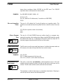
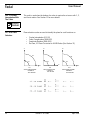
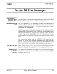
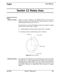
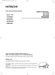
Fadal User Manual Section 3: G Codes G0 Rapid Travel G0 moves from one point to another point at the maximum traverse rate of the machine. G0 is generally used when cutting will not take place when moving from one location to another. Multiple axis moves begin by all axes moving together at the same rate until each axis move is completed. This gives the appearance of a forty-five degree move at the beginning of the move. For the remaining distances, each axis will continue to move to the end point. When using MDI, a rapid Z axis move will move independent of the X, Y, A & B axes. When the Z axis is to move in the positive direction, it moves prior to X, Y, A, & B axis motion. When the Z axis is to move in the negative direction, it moves after X, Y, A, & B axis motion. G0 is modal and will remain in effect until it is canceled by the G1, G2 or G3 codes. G0 will not cancel any feed rates used by the interpolation modes. An F word can appear on the same line with a G0 code, however, the F word will only be used when an interpolation code is used. G0 can appear at any point on a line to make all moves on the line rapid. The rapid travel switch on the pendant can be used to alter the rapid travel rate. The feed rate potentiometer will only affect the rapid rate during single step, just after a slide hold, and while in any of the dry run modes. See also G5 Non Modal Rapid. EXAMPLE: April 2003 F30. (This F word is modal). G0 G90 Z.1 (This line will be in rapid travel). X1.3 Y2.7 (This line will be in rapid travel). G1 Z-.245 (The G1 will cancel the G0 and use the F30. from above). G91 X.5 (This will be at F30.0). G90 Z.1 G0 (This line will be in rapid travel). Section 3: G Codes 47 Fadal User Manual G1 Linear Interpolation This code is used for linear interpolation. Linear moves can be made by one, or any combination of, all the active axes. See Section 13 for more details on linear interpolation. See also Section 12 for rotary axis interpolation details. Note: Max program feedrate at 100% is 400 IPM. G2 Circular Interpolation Arc Clockwise G2 is used for CW circular interpolation and helical moves. See Section 13 for more details. G2 X1. Y1. I-1. J0 Note: Max program feedrate at 100% is 400 IPM. G3 Circular Interpolation Arc Counterclockwise G3 is used for CCW circular interpolation and helical moves. See Section 13 for more details. G3 X1. Y1. I-1. J0 Note: Max program feedrate at 100% is 400 IPM. Whenever a pause in the program is required, use the G4 code. G4 Dwell A pause may be used to allow the spindle and coolant to fully turn on after using the M3 and M7 or M8 codes. This often happens with a tall part or fixture, where the tool gets to the top surface before the spindle is up to speed. EXAMPLE: G90 G0 S10000 M3 E1 X-.45 Y-.2 H1 Z-.3 M8 G4 P1000 (This one second dwell allows the spindle to come up to speed). X3. G1 F80. • • • • A P word represents time. The time is given in milliseconds. P1 = 1/1000 second (or one millisecond) P500 = 500 milliseconds or 1/2 second P60000 = 1 minute The G4 would also be used in a situation where the tool needs to dwell to allow for spindle rotation, such as a spot face or counter bore situation. A general rule to follow is to dwell for at least three revolutions. To calculate elapsed time 48 Section 3: G Codes April 2003 Fadal User Manual during three revolutions divide 180,000 by the RPM used. The 180,000 represents time in milliseconds for three minutes. EXAMPLE: For 5000 RPM:180,000 / 5000 = 36 G1 F10. Z-.25 G4 P36 (Dwell for 36 milliseconds; 3 revolutions at 5000 RPM). Z0 G0 G4 as an In-position Check The use of a G4 without the P word will perform an in-position check. This would be non-modal and would only affect the line in which it existed. See also G9. X1.0 G4 (An in-position check is forced here). X2.0 X3.0 G4 as a Program Stop 9 SPECIAL FEATURE G5 Non Modal Rapid 9 SPECIAL FEATURE EXAMPLE: G8 Acceleration (No Feed Ramps) TIME SAVER The use of a G4 with P66000 forces an endless dwell or a program stop, placing the machine in the waiting state. When in the WAITING state the spindle and coolant will remain on, as opposed to M0 and M1 which turn them off. To continue program execution press the Start or Auto button. The G5 code is used for non modal rapid moves. It exhibits the same motion as G0, however, this code will only affect the line in which it exists. X2.5 G1 F20. G5 Z.1 (Rapid movement of this line only). X3.0 Y-2.5 (The G1 is still in effect from above). This code is used when no hesitation is desired between moves. If the tool hesitates the tool pressure lessens and the tool will leave a tool mark on the contour. The G8 code would be used to eliminate the tool marks. The hesitation is called a feed ramp or acceleration-deceleration. Ramping is used to help the tool move to the desired position. April 2003 Section 3: G Codes 49 Fadal User Manual • • • • • EXAMPLE: G0 G8 G90 (Ramping is off at this line). G2 I.5 G91 Z.02 L7 X-.5 G41 X.55 Y-.55 I.55 G3 • G9 Deceleration (Feed Ramps) The G8 code is often used in combination with the M92 code. This code is modal and will remain in effect until the G9 code is used. The G8 code is a default code for format two. The G8 code is incompatible with a G41 or G42 coded on the same line. The G9 code is used to cancel the G8 code. The M95 code is used as a non modal form of the G9 code. It is generally used when G8 is in effect. See M95 for more details. This code is used when hesitation is desired between moves. When the tool hesitates the tool pressure lessens and the tool will leave a tool mark on the contour. The G9 would be used to help the tool move from place to place when inertia may be a problem. The use of the G9 code as opposed to using the G8 code will help insure contouring accuracy. If an axis is faulting at a certain move, the G9 could be used to help the machine to get through the move by decelerating at the end of the move and then accelerating again at the beginning of the next move. The deceleration will only slow the tool down at the end of the move. (It will not come to a complete stop). • • EXAMPLE: G9 as an In-Position Check 50 This code is modal and will remain in effect until the G8 code is used. This code is default for format one. X1.0 G9 X2.0 X3.0 To stop the tool completely at the end of each move, an in-position check must be used. The G9 code, used in succession on two or more lines, causes an inposition check. Because of the look ahead processing, the line with the first G9 in successive order will use the in-position check. See also G4 and M95 for other forms of in-position check. Section 3: G Codes April 2003 Fadal User Manual EXAMPLE: G10 Programmable Data Input X1.0 G9 (Because of the look ahead, the first G9 will be an in-position check). X2.0 G9 (In-position check). X3.0 G9 (In-position check). This code is used to replace, alter, or read the values of fixture offsets, tool offsets, and parameters R0 through R9. • • • • • • L2 When G10 is used in the absolute mode (G90), the current value is replaced by the value identified by X, Y, Z, R0, or P. In the incremental mode (G91), the current value is altered by the positive or negative value of X, Y, Z, R0, or P. L# identifies the operation. P# selects the offset # or identifies the value for parameter R0 - R9. X#, Y#, Z# identifies the axis and the value to be changed. R0# identifies the value. Used to replace or alter fixture offsets: L2 P# (0, 1- 48) X# Y# Z# A# B#. With G90 G10 L2 P5 X1.356 Y2.63 Z-.01 (This replaces the current value of fixture offset #5 with X1.356 Y2.63 Z-.01). With G91 G10 L2 P5 X-1. (This subtracts one inch from the current X value of fixture offset #5). L2 Used to offset the part home position with a coordinate system shift (see G52). With G90 or G91 G10 L2 P0 X1. Y1. (P0 functions as a G52 X1. Y1.). April 2003 Section 3: G Codes 51 Fadal User Manual L10 Used to replace or alter tool length offsets: L10 P1-99 R0# With G90 G10 L10 P12 R0 -5.467 (This replaces the current value of TLO #12 with 5.467). With G91 G10 L10 P12 R0+1. (This adds one inch to the current value of TLO #12). L12 Used to replace or alter a tool diameter: L12 P1-99 R0# With G90 G10 L12 P1 R0+.52 (This replaces the current value of dia. offset #1 with .52). With G91 G10 L12 P1 R0-.02 (This subtracts .02 from the current value of dia. offset #1). L13 Used to read the values of a fixture offset: L13 P0,1-48 With G90 or G91 G10 L13 P2 (The R0 variable = the Z amount, the R1 = X, and the R2 = Y). L14 Used to read the value of a tool length offset: L14 P1-99 With G90 or G91 G10 L14 P2 (The R0 variable = the offset amount of TLO #2). L15 Used to read the value of a diameter offset: L15 P1-99 With G90 or G91 G10 L15 P2 (The R0 variable = the offset amount of diameter #2). 52 Section 3: G Codes April 2003 Fadal User Manual L100 - L109 Used to replace or alter the value of a variable: L100 P# With G90 G10 L102 P-6.5 (This replaces the current value of the R2 variable with -6.5). With G91 G10 L102 P+.543 (This adds .543 to the current value of the R2 variable). T Used to facilitate turret tests. With G90 or G91 O5805 (WORK TOOL CHANGER L100 G10 T1 M6.1 T1 T-2 M17 M30 L199 (PUT A TOOL IN SPINDLE M0 (FINISHED TEST April 2003 Section 3: G Codes 53 Fadal G15 YZ Circular Interpolation With The A Axis 9 User Manual This code is used when the bottom of a cutter is required to cut an arc with Y, Z, and A axis motion. See Section 12 for more details. SPECIAL FEATURE G17-G19 Plane Selection Plane selection codes are used to identify the plane for such functions as: • • • • Circular Interpolation (G2, G3) Cutter Compensation (G40-G42) Coordinate Rotation (G68, G69) Flat Cam, XY Plane Conversion to XA/XB Motion (See Section 12) Y+ Z+ Z+ G2 G2 G3 G3 X+ X+ G17 G18 VIEW FACING MACHINE LOOKING ZTOOL MOTION 54 G2 G3 VIEW FACING MACHINE LOOKING Y+ TOOL MOTION Section 3: G Codes Y+ G19 VIEW FACING MACHINE LOOKING XTOOL MOTION April 2003 Fadal User Manual G17.1-G17.2 A/B Word Swap 9 SPECIAL FEATURE The G17.1 word activates B-axis command substitution for the A-axis command. This allows the use of the A axis rotary moves in one program for use with rotary heads on both pallets. If the program calls for an A axis move and the rotary device is connected to the B axis controller, the G17.1 code will swap the A word for a B word. Existing programs written for the dual 4th axis setups that contain both A and B words are allowed. The G17.1 will automatically swap the B words to A words. The G17.2 word cancels A/B axis command swap mode. G20 Inch Programming This code is used to verify that the operator has set the CNC to the INCH mode. This code does not place the machine in the inches mode. The inch mode is set with the SETIN or SETP command. See Section 8, SETIN and SETP commands. See also the G70 code. G21 Metric Programming This code is used to verify that the operator has set the CNC to the METRIC mode. This code does not place the machine in the metric mode. The metric mode is set with the SETME or SETP command. See Section 8, SETME and SETP commands. See also the G71 code. G28 Return to Zero This code is used to return all axes (Format 1) or a specific axis (Format 2) to the current Tooling Coordinate System (Home Position). The G28 code acts the same in absolute and incremental mode. Format 1 Typically it is used to move home after a G92 or G52 code is used. The G28 will ignore the G92 preset position or a G52 shift and move to the positions established by the SET(X,Y, Z, A, B or H) commands or by a fixture offset. The G92 and G52 codes will remain in effect after the G28 move. If a fixture offset is in effect, the G28 will return all axes to the fixture home position, unless a motion word appears with the G28 code. The G28 will not cancel the fixture offset. If a Z offset is in effect that is larger than +4.0 inches and the Z axis SET position is at the cold start position, the Z axis will over travel on the G28 line. It would be best to not use a G28 in this case. Instead, use an M6 to cancel the Z offset, then use an E0 X0 Y0. • • EXAMPLE: April 2003 This code will cancel an H word if it is in effect. Motion words to a position in the same block with a G28 will be executed before the G28 and the position will be retained as the initial position during execution of a G29 code. M5 M9 Section 3: G Codes 55 Fadal User Manual G28 All axes will move to the current home position M0 (OPERATOR CHANGE CLAMPSL EXAMPLE: Format 2 EXAMPLE: M5 M9 G28 Y6. The Y axis will move to Y6.0 (the initial position) then all axes move home Format 2 programming requires the axis to be specified in the block with the G28 for it to move to that position. G28 Z0 Only the Z axis will move to the zero position G28 X0 Only the X axis will move to the zero position G28 will cancel the current fixture offset and move to the location established with the motion word on the same line as the G28 code, unlike Format 1 where G28 moves to the location in reference to the last called out fixture. The G28 moves are relative to the CS position or the SETX, SETY, SETZ, SETA, SETB, or SETH commands, whichever was used last. G28.1 Cancel JOG AWAY This code is used to cancel the jog away amount and return specified axes to the current programmed position. This code is only intended to be used with option number two from the jog away return selection menu. The G28.1 code acts the same in absolute and incremental mode. EXAMPLE: Table 1: Cancel Jog Away PROGRAMMED POSITION MACHINE POSITION JOG AWAY OFFSET X3.0 Y3.0 X3.1000 Y3.1000 X0.1000 Y0.1000 G28.1 X0 X3.0000 Y3.1000 X0.0000 Y0.1000 Note: The value in the axis word with the G28.1 is irrelevant and is only used to determine which axis to cancel jog away. G29 Return from Zero EXAMPLE: 56 This code is used to return all axes to the initial position established with the last G28 code used in the program. Motion words in the same block as the G29 will be executed after the axes are returned to the initial position. G29 X5.0 Section 3: G Codes April 2003 Fadal User Manual This only returns the X axis to the INITIAL position before moving incrementally the programmed amount. All other axes remain at their current location. G31 Probe Touch Function The G31 is only used in conjunction with a probe. This code causes the machine to stop motion when the probe is touched and then execution continues at the next line in the program. The G31 can be used with table or spindle probes (see also G31.1). • • • • • • • The motion can be defined in absolute or incremental terms. The positions can be stored with a P word, a macro V variable, and output through the RS232 port. All G31 moves must be G1 linear moves; no G0, G2, or G3 moves are allowed. Rotation can be in effect when the G31 is used. CRC should not be in effect when G31 is used. Mirrored axes should be canceled before using the G31 code. Fixed cycles need to be canceled before using the probe. Note: Program a move that would normally be excessive. For example if a one inch move is required to get the probe up to a wall, use a two inch move in the program. The probe will stop the motion, and whatever motion is remaining for that line will be discarded and the control will continue execution of the program at the next line. Expect some over travel, if the feed rate used with the move is high, and also if the stylus in the probe is long. A method for accuracy would be to use the G31 and the G31.1 codes together. Use the G31 at a high feed rate to get up to the wall. With the high feed rate the stylus is angled and over the edge because of the time required to read the probe and stop the motion. Then reverse the motion to move away from the wall with the G31.1 code in the line. Do this at a slow feed rate. At F1. the motion is slow enough that it will usually stop within one tenth. The G31.1 will stop motion when the probe is not touching. This means that the stylus will be perpendicular to the table and directly at the edge of the wall when the probe is not touching. If the stylus is not running true, or a chip is in the spindle, the probe will not give a true position reading. For consistency, use an M19 to orient and lock the spindle at the same position each time the probe inserted in the spindle. If an operator is to place the probe in the spindle by hand, orient the spindle prior to inserting it in the spindle. Sometimes the stylus will work itself loose, confirm that it is tightly screwed in before using the probe. April 2003 Section 3: G Codes 57 Fadal User Manual Storing Probed Positions Saving Positions Through the Rs-232 Port 1) Any software designed to save data from the port will be sufficient to retain the data. 2) When a touch is made, the motion will stop and the current position will be output through the port. G1 G31 X1. F50. This line sends just the X axis location to the port G1 G31 X2. Y5. F50. This line sends the X and Y locations to the port G1 G31 X3. Y-4. Z-2. F50. This line sends the X, Y and Z locations to the port 3) Macro SPRINT statements can be used just before the probe line to identify the information being saved. #SPRINT “PROBE TOUCH #1:” G1 X1. Y1. G31 Saving Positions to P Words 1) P1, P2, and P3 are used to save the touch positions when the fixed probe subroutines are going to be used in the program. See Touch Probe, Section 15. G1 X3. Y-6. G31 P1 The first touch position is saved to P1 X0 Y0 G5 G1 X0 Y6. G31 P2 The second touch position is saved to P2 X0 Y0 G5 G1 X-3. Y-6. G31 P3 The third touch position is saved to P3 L9101 R1+2. Use probe fixed subroutine function #2 to find center 2) P1, P2, and P3 can be used with the macro PX1-3, PY1-3, PZ1-3, PA1-3, and PB1-3 variables. When a probe touch (G31) or probe no-touch (G31.1) is used on a line with a P1, P2, or P3 each axis position is stored regardless of the axis that moved to get the touch point. G90 G0 X3. Y-6. Z1. H21 G1 F30. G31 Z-2. F1. Z0 G31.1 P1 P1 has stored the XYZAB position at this line #V1=PZ1 #PRINT “THE TOUCH POINT IS: X”,PX1,", Y",PY1,", AND Z",PZ1 Saving the Position As a V Variable 58 1) The current position can be saved to a V variable by using a macro AX, AY, AZ, AA, or AB command. Section 3: G Codes April 2003 Fadal User Manual G90 G1 X4. Y4. G31 F50. X0 Y0 G31.1 F1. #V1=AX This saves the X position to V1 #V2=AY This saves the Y position to V2 G31.1 Probe No Touch Function This code causes the machine to stop motion when the probe is not touching and then execution continues at the next line in the program. The G31.1 can be used with table or spindle probes. This code functions exactly like the G31 code. See also G31. G40 Cutter Compensation Cancel This code is used to cancel cutter radius compensation. See Section 9 for details. G41 Cutter Compensation Left This code is used to activate cutter radius compensation to the left. See Section 9 for details. G42 Cutter Compensation Right This code is used to activate cutter radius compensation to the right. See Section 9 for details. G43 Tool Length Compensation Positive This code is used to apply tool length compensation to the Z axis in the positive direction. This code is not required in programs primarily running on the FADAL control. This code is supported for compatibility with other controls. The direction of motion is determined by a combination of the sign of the offset value and the programmed G code (G43, or G44). See the chart below with G44. G44 Tool Length Compensation Negative This code is used to apply tool length compensation to the Z axis in the negative direction. See the chart below. This code is not required in programs primarily running on the FADAL control. This code is supported for compatibility with other controls. The direction of motion is determined by a combination of the sign of the offset value and the programmed G code (G43, G44). Table 2: Table Offset Code April 2003 If the offset in the table is + If the offset in the table is - G43 Tool moves in plus direction Tool moves in minus direction G44 Tool moves in minus direction Tool moves in plus direction Section 3: G Codes 59 Fadal User Manual G45 Tool Offset Single Expansion This code is used for extending the programmed axis move by a value stored in the tool offset table. The value is determined by an H word. Program the H word in the same block with the G45 code and an axis move. Only the block containing the G45 code is extended. Note: The G45, G46, G47, or G48 codes may only be used in X only, Y only, or quarter arc moves. No angular movements or full circles are allowed. These codes were commonly used before CNC equipment had cutter radius compensation and fixture offsets. EXAMPLE: G0 G91 G45 X1.0 H1 The above example extends the 1.0 axis move by the tool length value of offset #1. Tool length offset is not applied to the Z axis. To restore extended values to the original programmed values, a single reduction must be programmed in the opposite direction. See G46. 60 Section 3: G Codes April 2003 Fadal User Manual G46 Tool Offset Single Reduction EXAMPLE: This code is used for reducing the program axis move by a value stored in the tool offset table. See G45. G0 G91 G46 X-1.0 H1 G47 Tool Offset Double Expansion This code is used for extending the program axis move by a value stored in the tool table. It is similar in function to a G45, but the value determined by the H word is doubled. See G45. G48 Tool Offset Double Reduction This code is used for reducing the program axis move by a value stored in the tool table. It is similar in function to a G45, but the value determined by the H word is doubled. See G45. G49 Tool Length Offset Cancel This code cancels the current tool length offset programmed by the H word. It causes the Z axis to move in the opposite direction and distance of the offset in the tool table. • April 2003 If the position of the Z axis is more than four inches above the program Z zero, using this code will cause the machine to over travel in the Z axis. If the tool is higher than four inches, use a G53 Z0 in place of the G49 Z0 codes. If the G53 Z0 is used, the M6 will automatically cancel the tool length offset. EXAMPLE: Z4.5 G80 M5 M9 G53 Z0 Use G53, not G49 when the Z is more than 4. above Z0 M6 T2 This code is similar to using the H0 code to cancel a tool length offset EXAMPLE: G90 G0 H0 Z0 or G90 G0 G49 Z0 Both would function the same M6 T2 This code is used at the end of a program just before the M2 or M30 codes EXAMPLE: G90 G0 G49 Z0 E0 X0 Y0 M2 This code is used on a line just before each M6 line to prevent over travel or tool crashes during direct mid tape starts on the tool change line Section 3: G Codes 61 Fadal User Manual G50 Ramp Control Cancel This code resets the ramp control to the default values. See G51. G50.1 Mirror Image Cancel This code is used to deactivate the mirror image mode. EXAMPLE: G51 Ramp Control TIME SAVER G51.1 X0 X3. Y-3. G50.1 Deactivates mirror image This code is used to increase or decrease the length of time for the feed ramps between moves. A feed “ramp” is the time against feed rate on a graph. When a feed rate is specified it requires the user to specify the amount of time to reach that feed rate and a specify the amount of time to slow down at the end of a move. Imagine a truck at a stop sign. It takes a certain amount of time to get up to speed, as opposed to a car at the same stop sign, it would take less time to get up to speed. With less weight on the table, the ramps could be reduced. With a heavier weight on the table, the ramps may need to be lengthened. A value between .5 and 2, default being 1, is specified with the R0 word. Values less than 1 will decrease the time, and values greater than 1 will increase the time. The sign (+ or -) of the value identifies the controlled axis. For example, R0 used with a negative value controls the ramp length of the X and Y axis. Positive values control the Z axis. EXAMPLE: G51 R0-.6 This will decrease the length of all XY feed ramps G51 R0+.6 This will decrease the length of a Z axis feed ramps • • • 62 Use the R0- and R0+ on separate lines. This code sometimes has a significant effect on the amount of time required to execute a particular program. When the feed ramps are shorter, the time to execute the program is reduced. The more moves that are involved in the program the more significant the time savings. The opposite effect would result if the ramps were lengthened. The shorter the ramps, the more stress is placed on the machine. If the machine does not respond favorably to shortened ramps, either don’t adjust them or lengthen them. The undue stress will affect the axis system for each axis unfavorably and cause premature breakdown. The operator will notice excessive noise from the axes, hot motors, axis Section 3: G Codes April 2003 Fadal User Manual amplifier faults, and motor overload faults. If the operator notices any of these symptoms, lengthen the ramps. G51.1 Mirror Image This code activates the mirror image mode. The axes to be mirrored are identified in the same block with the G51.1 code. EXAMPLE: G51.1 X0 Only the X axis will be mirrored G51.1 X0 Z0 Both X and Z will be mirrored • • • • • EXAMPLE: April 2003 No motion will result from a block containing the G51.1 code. The mirror mode can be initiated from any position, but for all practical uses, it should be initiated from the zero position of the axis to be mirrored. This is especially true in absolute. Absolute and incremental moves can be mirrored. Use G50.1 to cancel the mirror mode. When mirroring contouring moves, the climb cuts become conventional and vice-versa. The program may require the G41 codes to be changed to G42. This is something that a programmer must determine. Sometimes left handed cutters with M4 can be used with contouring moves that have been mirrored. G0 G90 E1 X0 Y0 Move to the zero position of the axis to be mirrored H1 Z.1 M7 G51.1 X0 Y0 Mirror X and Y G1 Z-.25 F40. X1. Y0 Mirror image position X-1.0 Y0.0 Y-1. Mirror image position X-1.0 Y1.0 X0 Mirror image position X+0.0 Y1.0 G50.1 Cancel Mirror image Section 3: G Codes 63 Fadal User Manual G51.2 Tool Load Compensation (TLC) 9 OPTIONA L This code activates the Tool Load Compensation (TLC) option. The G51.2 and the following parameters have been designed to automatically adjust the feed rate according to tool load conditions. This option is a time saver because the feed rates can be increased automatically when conditions allow. Instead of using a generalized “safe” feed rate, the feed rate can be calculated for the maximum condition, and then automatically reduced by tool load conditions when it is being cut. R1 = Target Spindle Load (percentage) The R1 variable represents the target spindle load to maintain. If the tool load is less than this amount, the feed rate will be increased; if the tool load equals or exceeds this amount, the feed rate will be reduced. R2 = Minimum Percentage Feed Rate Reduction The R2 parameter represents the lowest percentage to modify the feed rate. The lowest modification allowed is 20 percent. By reducing the feed rate the chip load will also be reduced. If the R2 parameter is too low, the reduced feed rate may cause excessive tool wear. R3 = Maximum Percentage Feed Rate Increase When cutting conditions are correct and the spindle load is lower than what the R1 parameter is set for, the feed rate will be modified by the R3 percentage. This parameter must be considered carefully because it will affect the chip load of the tool. If the feed rate increases, so does the chip load. If the chip load increases too much it may cause the tool to break. It is suggested to select a maximum percentage for which the tool is designed. To determine this percentage, select an appropriate feed rate, multiply it by two thirds (.66666), and use the result for the feed rate in the program. Use an R3 value of +150. with G51.2 code. For example, if the appropriate feed rate is 30. then 30.*.66666=19.9998 or 20. Modifying 20. by 150% will result in maintaining the appropriate feed rate when the spindle load is lower than the target load factor. R4 = Number of Seconds at Minimum Feed Rate Until the Control Activates Slide Hold If the feed rate is programmed at the lowest feed rate modification established by the R2 parameter for longer than the R4 parameter value, the machine will be placed in SLIDE HOLD. The R2 parameter is the lowest feed rate modification. When used, it is an indication that the tool is getting dull or the cutting condition is excessive for the tool. The time to remain in this condition must be determined carefully. It must be short enough to force the machine into slide hold when appropriate, and long enough to allow for intermittent periods of expected high load conditions. Suggested parameters are given in the following example: EXAMPLE: 64 G0 G90 E1 X0 Y0 Section 3: G Codes April 2003 Fadal User Manual H1 Z1. M7 G51.2 R1+60.0 R2+50.0 R3+150.0 R4+15.0 Activate TLC G1 F100. Z-.1 ** cut part** G51.2 R1+0.0 Cancel TLC M6 T2 An M6 will also cancel TLC Note: The feed rate to be modified is on the line after the line where the G51.2 was used. No other feed rates should appear after the initial feed rate or until the G51.2 is canceled. Canceling G51.2 (TLC) Use the G51.2 R1+0 in the program at the point where TLC is to be canceled. An M6 will also cancel the TLC mode. See the program example above. TLC Manual Target Power Override When the TLC is active in AUTO, the parameters will be displayed in the upper right portion of the screen. As the control adjusts the feed rates, the display will reflect the changes as they occur. During AUTO the operator may press the + or - button to manually override the specified target load parameters. TAR%:60% Target Power R1 G51.3 Axis Scaling EXAMPLE: MOD%:100% Programmed Feed Rate POW%: 100% Actual Power This allows the programmer to scale all or individual axis dimensions. The G51.3 code with the R1# parameter will scale all axes. The R2# will scale the X axis only. The R3# is used for the Y axis, and the R4# for the Z axis. The # with the parameters represents a percentage to scale. The percentage is represented in the decimal form. For example 2.0 would double the size, .5 would half the size. N1 O1 (PART 1234 ** Cut part ** N2 M6T1 (TOOL #1 N3 G0 G90 S2500 M3 E1 X0Y0 N4 H1 D1 Z.1 N4 G51.3 R1+2. Scale all axes by 2 times scale factor 2 ** Cut part ** N4074 G51.3 R1+1. Cancel scaling or scale factor 1 N4075 G0 G90 H0 Z0 Circular moves will be scaled according to the axis being scaled. If the X axis is scaled, the I for the circle center description will be scaled in the same proportion. The same would apply for the Y and Z axis. When the circles are to April 2003 Section 3: G Codes 65 Fadal User Manual be scaled, it is suggested that the axes of the plane selection be scaled proportionally. For example, in G18 the X and Z axes should be scaled at the same percentage. G52 Coordinate System Shift This code is used to shift the current Tooling Coordinate System (TCS) similar to the way a fixture offset would be used except that the data for the shift is coded in the program. The current TCS would have been established by either the CS command, the SETH or SET(axis letter) commands, the G92 code, or the fixture offset codes G54-59 and E0-48. This code is used when an absolute subroutine or subprogram needs to be used at different locations. Whereas an incremental subroutine or subprogram can be repeated from any location. Note: G52 does not cause any motion to take place. It only references the new location on relation to the original zero. EXAMPLE: 66 L100 (SUB FOR POCKET G90 G0 X2.Y-2. Z-.1 G1 F10. X2.5 G41 F30. Y-1. X1.5 Y-3. X2.5 Y-2. X2. G40 Z.1 G0 M17 M30 — Program Body — X2. Y-2. This is the original position L101 Call subroutine 1, 1 time G52 X2. Shift original X0 position 2 inches from home L101 Call subroutine 1, 1 time G52 X4. Shift original X0 position 4 inches from home L101 Call subroutine 1, 1 time Section 3: G Codes April 2003 Fadal User Manual Cancel G52 G53 Machine Coordinate System G52 X0 Shift is canceled to original X0 home The G52 shift amount is canceled by using another G52 in the program with a zero shift amount. See the program example above. This code causes the control to use the machine tool coordinate system. The machine tool coordinate system is established when the cold start, CS command was used. This code is useful when it is desired to move to an object that is secured to the table. The object may be something that is used by many fixtures or tools from many different jobs. One use may be the TS-27 probe for setting tools. Another use may be a diamond, used for dressing grinding tools. The G53 is a non modal code. It will affect only the line in which it exists. EXAMPLE: G90 X0 Y2. This position is relative to the part home G53 Y0 The tool will move to the cold start Y0 position Y0 This position is relative to the part home • • EXAMPLE: M5 M9 G53 Z0 M6 T4 G53 X-19.75 Y-9.8 (MOVE TO TABLE PROBE Z-30. G1 F60. G31 • April 2003 The G53 should be the only G code in the line. Code an X position, Y position or any axis position with the G53 to indicate where to move in relation to the machine tool coordinate system. A G53 Z0 is usually used on the line just prior to an M6. This will make a quicker tool change, and it offers some insurance when doing mid tape starts that the tool will not crash into the part. Section 3: G Codes 67 Fadal User Manual G54-G59 Fixture Offsets These codes may be used for fixture offset locations E1 - E6. Specify a G54 code to access fixture offset number 1, a G55 code for number 2, and up to a G59 code for number 6. For fixture offsets after number 6, the E words must be used. These codes are supported for compatibility and can be used in both format one and two. See Section 11, Fixture Offsets for more details. EXAMPLE: G66 Modal Subroutine 9 SPECIALF EATURE G0 G90 S3000 M3 G54 X0 Y0 H1 Z1. M7 This code defines a subroutine as being modal. The subroutine is executed at each X, Y, A, B position programmed or when an M45 is coded, in the same manner as any fixed cycle would be repeated. This code is a time saver (and a memory saver) in that the programmer does not have to type the sub call after each positioning move. It is a memory saver because the memory space used for each sub call is no longer needed. • • EXAMPLE: 68 Use G67 to cancel the modal subroutine call. Subs can be incremental or written in absolute. O1 L100 G0 G90 Z.05 G1 G91 X.2 Z-.05 F10. I-.2 G3 Z-.1 I-.2 G3 X-.2 G90G0 Z.05 M17 M30 M6 T1 G0 G90 S3000 M3 E1 X0 Y0 H1 Z1. M7 G66 L101 Defines subroutine 1 to be modal X3. Y-3. Repeat Subroutine 1 at this location X6. Y-3. Repeat Subroutine 1 at this location G67 Cancel G66 Section 3: G Codes April 2003 Fadal User Manual • EXAMPLE: Fixed subroutines and Fixed Cycles cannot be used in a subroutine that will be modal, however they can be in a subroutine that will not be modal. This is the incorrect form of fixed cycles and subroutines in a sub. O1 L100 G81 G99 R0+.1 Z-.5 F40. L9307 R0-.75 R1+0 R2+45. M17 M30 M6T1 (DRILL G90 G0 S10000 M3 E1 X3. Y-3. H1 Z.1 M8 G66 L101 Note: Example 2 is not possible without modification. This is the correctly modified form when fixed cycles and subroutines are in a sub. O1 L100 G67 Cancel the modal subroutine at the beginning of the sub G81 G99 R0+.1 Z-.5 F40. L9307 R0-.75 R1+0 R2+45. G66 L101 Make the subroutine L100 modal at this point M17 M30 M6T1 (DRILL G90 G0 S10000 M3 E1 X3. Y-3. H1 Z.1 M8 L101 The sub will be repeated at X3. Y-3. X6. The sub will be repeated at this location Y-6. The sub will be repeated at this location X3. The sub will be repeated at this location G67 The modal sub is canceled here April 2003 Section 3: G Codes 69 Fadal User Manual G67 Cancel Modal Subroutine The G67 cancels a modal subroutine. The G67 works in the same way as a G80 cancels a fixed cycle. X6. Y-3. Repeat Subroutine 1 at this location G67 Cancel modal Subroutine 1 G68 Coordinate System Rotation The G68 activates a mode to rotate the coordinate system of the current plane (Selected by G17, G18 or G19). In G17 only X, Y, I, and J are rotated. In G18 only X, Z, I, and K are rotated. In G19 only Y, Z, and K are rotated. The angle of rotation is coded in decimal degrees by the R0 word. A positive value designates counterclockwise rotation. A negative value designates clockwise rotation. An X, Y or Z word coded with the G68 defines the rotation center and must be in absolute (G90) terms. All parameters must be in the line with the G68 code. EXAMPLE: G68 R0+.56 X0 Y0 Rotate the program around X0 Y0 +.56 degrees G68 R0-1.2 X1. Y-.5 Rotate the program around X1. Y-.5 by - 1.2 degrees Rules • • • • • • EXAMPLE: 70 CRC can be used after rotation is in effect and should be canceled before G69 is used. A part program cannot be rotated while CRC is in effect. Rotation continues until a G69 is coded. Fixture offsets are allowed with rotation. The moves to the offsets are not rotated. Rotation must be established prior to Fixed Cycle definitions and affects only the positions for execution. Fixed cycles and Fixed Subroutines will not be rotated to another plane. All X and Y (or X, Z or Y, Z or X, Y, and Z) positions are required for linear moves, even if they are zero or non-motion moves. In the selected plane, all X, Y, I and J (or X, Z, I, K or Y, Z, J, K) positions are required for circular moves, even if they are zero or non-motion moves. G17 G0 G90 E1 X0 Y.25 H1 Z.1 G1F5. Z-.3 G68 X0 Y.25 R0+45. X0 Y0 G41 CRC turned on after rotation X1.0 Y0 G1 F30. Code Y even though it is a non-motion move Section 3: G Codes April 2003 Fadal User Manual X1.0 Y.5 I0 J.25 G3 Code X even though it is a non-motion move X0 Y.5 Code Y even though it is a non-motion move X0 Y.25 G40 Code X even though it is a non-motion move G69 Cancel rotation G69 Coordinate System Rotation Cancel This code cancels the coordinate system rotation mode (see G68 for program example). G70 Inch Programming This code is used to verify that the operator has set the CNC to the INCH mode. This code does NOT place the machine in the inches mode. The inch / metric mode is set with the SETIN or SETP command. See Section 8, SETIN and SETP commands. G71 Metric Programming This code is used to verify that the operator has set the CNC to the METRIC mode. This code does NOT place the machine in the metric mode. The inch / metric mode is set with the SETME or SETP command. See Section 8, SETME and SETP commands. G73-G76, G81-G89 Fixed Cycles These are a preset series of operations which direct Z axis movement and/or cause spindle operation to complete such actions as boring, drilling, tapping. The fixed cycle selection is modal. The cycle is repeated after each M45 or X, Y, A, or B axis move, until the cycle is canceled by a G80. See also Chapter 4, Fixed Cycles. G80 Fixed Cycle Cancel This code cancels the current fixed cycle. EXAMPLE: N13 X1.0 Y1.0 N14 G80 In Format 1, the Z axis will return to the initial plane. In Format 2, the Z axis will return to the plane indicated by the use of the G98 or G99 code. April 2003 Section 3: G Codes 71 Fadal User Manual G90 Absolute Input A control mode in which the motion data input is in the form of absolute dimensions. The values programmed with the axis words are the locations to move to in relation to the current zero position. See also Coordinate System, Section 11. Since blocks are processed in a left to right order, both G90 and G91 may appear in the same block. G90 and G91 are position sensitive, therefore the moves to the left of the G90 code will be in absolute until the G91 code is used. The G90 code is modal and will remain in effect until the G91 code is used. EXAMPLE: G91 Incremental Input N12 G90 X2. G91 Y1. The X move will be absolute, the Y move will be incremental N13 Z-.02 G5 This Z move will be incremental N14 G90 X4. This X move will be absolute This is a control mode in which the motion data input is in the form of incremental data. The values programmed with the axis words are the distance and direction to move in relation to the current location. Since blocks are processed in a left to right order, both G90 and G91 may appear in the same block. G90 and G91 are position sensitive, therefore the moves to the left of the G91 code will be in incremental until the G90 code is used. The G91 code is modal and will remain in effect until the G90 code is used. EXAMPLE: 72 N12 G90 X2. G91 Y1. The X move will be absolute, the Y move will be incremental N13 Z-.02 G5 This Z move will be incremental N14 G90 X4. This X move will be absolute Section 3: G Codes April 2003 Fadal User Manual G91.1 High Speed Execution 9 SPECIAL FEATURE A control mode which enables high speed data block execution. Using the 1400-2 processor, the CNC executes up to 72 data blocks per second throughput, whereas normal execution is about 22 per second. • When using the 1400-3 or -4 processor, it is not necessary to use G91.1, since the throughput is 250 data blocks per second. In G91.1 mode, motion words must be programmed in incremental and be segmented. Mid-program (-tape) starts are not allowed in this mode. Subroutines or subprograms are not allowed in this mode. The following codes are the only codes allowed during this mode of execution: G0, G1, G2,G3, G8, G9, M2, M3, M4, M5, M7, M8, M9, M95, X#, Y#, Z#, A#, B#, F#, I#, J#, K#, S#. Note: This is best used in Format 2. The G91.1 code is canceled with the G91.2 code. Format 1 G90 cancels the G91.2. G91.2 High Speed Execution Cancel (Format 2 Only) The G91.2 is used to deactivate the high speed execution mode in Format 2 only. High speed execution is best used in Format 2. The G91.1 code is canceled with the G91.2 code. See Section 2, M Codes, M94.1 for high feed rate machining. G92 Absolute Preset The G92 is used to establish a temporary Program Coordinate System (PCS). The axis words coded in the same line with the G92 establish the current axis position to those axis words. For example, G92 X3. Y2. would establish the current position of the machine to X3. Y2. Then all subsequent axis words will be relative to this new position. A G28 code can be used to return to the original tool coordinate system. To cancel the G92, move to the original tool coordinate system with a G90 G28 X0 Y0 or equivalent move, then code a G92 X0 Y0. • EXAMPLE: April 2003 No other codes are allowed in the same block with the G92 except X, Y, Z, A, or B. G90 G0 X3.75 Y-4.65 G92 X2. Y0 Current location now is X2 Y0 Section 3: G Codes 73 Fadal User Manual G28 X0 Y0 Move to original home G92 X0 Y0 Cancels the previous G92 preset See also Section 11, Program Coordinate System. G93 I/T (Inverse Time) Feed Rate Specification (IPM/ inches, DPM/ degrees) A control mode in which the feed rate is specified as one divided by the time to complete the move. This value is usually computed by dividing the desired feed rate by the length of the actual tool path. See Rotary Axes, Section 12, for more details. G94 Feed Rate Specification MMPM, IPM or DPM This is the default code and does not need to be coded in the program. The mode insures that the feed rate will be specified by Millimeters Per Minute, Inches Per Minute, or Degrees Per Minute. When rotary axes are programmed the feed rate is automatically in degrees per minute. When G93 is used, this code MUST be coded before a linear or rotary axis motion is programmed. See Rotary Axes, Section 12, for more details. G98 Return to Initial Plane This is a control mode in which, after performing the fixed cycle, the Z axis is returned to the Initial plane. This location is identified by the Z axis location prior to a fixed cycle definition. G90 H1 Z1. M7 G81 G98 R0+.1 Z-1. F20.X0 Y0 (AFTER DRILLING, Z RAPIDS UP TO INITIAL Z1. See Section 4, Fixed Cycles, for more details. 74 Section 3: G Codes April 2003