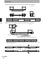
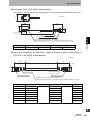
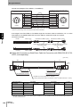
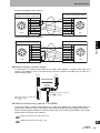
1
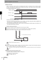
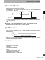
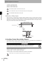
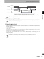
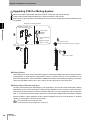
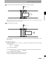
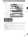
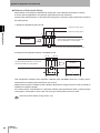
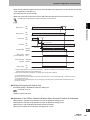
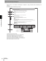
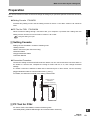
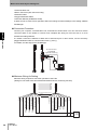
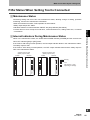
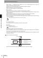
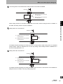
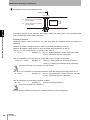
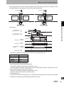
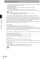
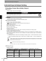
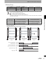
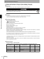
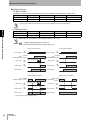
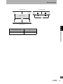
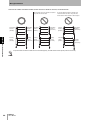
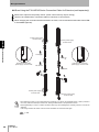
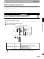
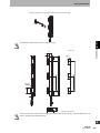
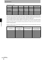
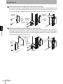
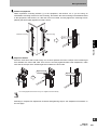
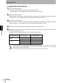
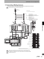
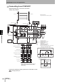
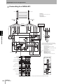
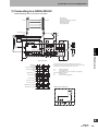
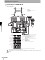
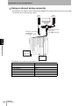
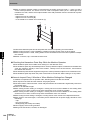
Wiring/Installation - Attaching/detaching of a cap or a series-connection cable may cause misalignment of rubber grommet in a connector assembly. Press the grommet to the bottom of the connector and attach the connector F3SJ again. Rubber Grommet Rubber Grommet Rubber Grommet in Right Position Misaligned Grommet 4 The external indicator output 1 (on the receiver side) is configured as "safety output reverse output Attaching External Indicators Chapter Output Operation (ON when blocked)", while the external indicator output 2 (on the emitter side) is configured as "lockout output (ON during lockout)". When the muting function is used, both the emitter and receiver are configured as muting/override output (Blinking during muting and during override). Timing chart of basic system Unblocked Unblocked /Blocked Blocked Safety output ON OFF External indicator output 1 ( Receiver ) ON External indicator output 2 ( Emitter ) ON OFF OFF Setting Change by the Setting Tool Functional setting is available through the setting tool. External Indicator Output (Non-Safety Output) p.74 •Changing output operation mode •Reversing output •Changing indication mode of external indicator •Enabling diagnosis function of external indicator 100 F3SJ-A User’s Manual Lockout