1
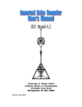
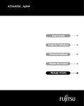
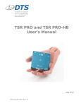
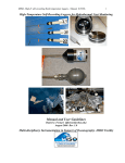
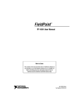
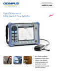
PCI
PCI-7041 User Manual
PCI-7041 User Manual
October 2002 Edition
Part Number 373360A-01
Support
Worldwide Technical Support and Product Information
ni.com
National Instruments Corporate Headquarters
11500 North Mopac Expressway Austin, Texas 78759-3504 USA Tel: 512 683 0100
Worldwide Offices
Australia 03 9879 5166, Austria 0662 45 79 90 0, Belgium 02 757 00 20, Brazil 55 11 3262 3599,
Canada (Calgary) 403 274 9391, Canada (Montreal) 514 288 5722, Canada (Ottawa) 613 233 5949,
Canada (Québec) 514 694 8521, Canada (Toronto) 905 785 0085, China 86 21 6555 7838,
Czech Republic 02 2423 5774, Denmark 45 76 26 00, Finland 09 725 725 11, France 01 48 14 24 24,
Germany 089 741 31 30, Greece 01 42 96 427, Hong Kong 2645 3186, India 91 80 4190000,
Israel 03 6393737, Italy 02 413091, Japan 03 5472 2970, Korea 02 3451 3400, Malaysia 603 9596711,
Mexico 001 800 010 0793, Netherlands 0348 433466, New Zealand 09 914 0488, Norway 32 27 73 00,
Poland 22 3390 150, Portugal 210 311 210, Russia 095 238 7139, Singapore 65 6 226 5886,
Slovenia 3 425 4200, South Africa 11 805 8197, Spain 91 640 0085, Sweden 08 587 895 00,
Switzerland 056 200 51 51, Taiwan 02 2528 7227, United Kingdom 01635 523545
For further support information, see the Technical Support and Professional Services appendix. To comment on
the documentation, send email to [email protected].
© 2002 National Instruments Corporation. All rights reserved.
Important Information
Warranty
The PCI-7041 is warranted against defects in materials and workmanship for a period of one year from the date of shipment, as evidenced by
receipts or other documentation. National Instruments will, at its option, repair or replace equipment that proves to be defective during the
warranty period. This warranty includes parts and labor.
The media on which you receive National Instruments software are warranted not to fail to execute programming instructions, due to defects
in materials and workmanship, for a period of 90 days from date of shipment, as evidenced by receipts or other documentation. National
Instruments will, at its option, repair or replace software media that do not execute programming instructions if National Instruments receives
notice of such defects during the warranty period. National Instruments does not warrant that the operation of the software shall be
uninterrupted or error free.
A Return Material Authorization (RMA) number must be obtained from the factory and clearly marked on the outside of the package before
any equipment will be accepted for warranty work. National Instruments will pay the shipping costs of returning to the owner parts which are
covered by warranty.
National Instruments believes that the information in this document is accurate. The document has been carefully reviewed for technical
accuracy. In the event that technical or typographical errors exist, National Instruments reserves the right to make changes to subsequent
editions of this document without prior notice to holders of this edition. The reader should consult National Instruments if errors are suspected.
In no event shall National Instruments be liable for any damages arising out of or related to this document or the information contained in it.
EXCEPT AS SPECIFIED HEREIN, NATIONAL INSTRUMENTS MAKES NO WARRANTIES, EXPRESS OR IMPLIED, AND SPECIFICALLY DISCLAIMS ANY WARRANTY OF
MERCHANTABILITY OR FITNESS FOR A PARTICULAR PURPOSE. CUSTOMER’S RIGHT TO RECOVER DAMAGES CAUSED BY FAULT OR NEGLIGENCE ON THE PART OF
NATIONAL INSTRUMENTS SHALL BE LIMITED TO THE AMOUNT THERETOFORE PAID BY THE CUSTOMER. NATIONAL INSTRUMENTS WILL NOT BE LIABLE FOR
DAMAGES RESULTING FROM LOSS OF DATA, PROFITS, USE OF PRODUCTS, OR INCIDENTAL OR CONSEQUENTIAL DAMAGES, EVEN IF ADVISED OF THE POSSIBILITY
THEREOF. This limitation of the liability of National Instruments will apply regardless of the form of action, whether in contract or tort, including
negligence. Any action against National Instruments must be brought within one year after the cause of action accrues. National Instruments
shall not be liable for any delay in performance due to causes beyond its reasonable control. The warranty provided herein does not cover
damages, defects, malfunctions, or service failures caused by owner’s failure to follow the National Instruments installation, operation, or
maintenance instructions; owner’s modification of the product; owner’s abuse, misuse, or negligent acts; and power failure or surges, fire,
flood, accident, actions of third parties, or other events outside reasonable control.
Copyright
Under the copyright laws, this publication may not be reproduced or transmitted in any form, electronic or mechanical, including photocopying,
recording, storing in an information retrieval system, or translating, in whole or in part, without the prior written consent of National
Instruments Corporation.
Trademarks
LabVIEW™, MITE™, National Instruments™, NI™, ni.com™, NI-DAQ™, NI-VISA™, RTSI™, and SCXI™ are trademarks of
National Instruments Corporation.
Product and company names mentioned herein are trademarks or trade names of their respective companies.
Patents
For patents covering National Instruments products, refer to the appropriate location: Help»Patents in your software, the patents.txt file
on your CD, or ni.com/patents.
WARNING REGARDING USE OF NATIONAL INSTRUMENTS PRODUCTS
(1) NATIONAL INSTRUMENTS PRODUCTS ARE NOT DESIGNED WITH COMPONENTS AND TESTING FOR A LEVEL OF
RELIABILITY SUITABLE FOR USE IN OR IN CONNECTION WITH SURGICAL IMPLANTS OR AS CRITICAL COMPONENTS IN
ANY LIFE SUPPORT SYSTEMS WHOSE FAILURE TO PERFORM CAN REASONABLY BE EXPECTED TO CAUSE SIGNIFICANT
INJURY TO A HUMAN.
(2) IN ANY APPLICATION, INCLUDING THE ABOVE, RELIABILITY OF OPERATION OF THE SOFTWARE PRODUCTS CAN BE
IMPAIRED BY ADVERSE FACTORS, INCLUDING BUT NOT LIMITED TO FLUCTUATIONS IN ELECTRICAL POWER SUPPLY,
COMPUTER HARDWARE MALFUNCTIONS, COMPUTER OPERATING SYSTEM SOFTWARE FITNESS, FITNESS OF COMPILERS
AND DEVELOPMENT SOFTWARE USED TO DEVELOP AN APPLICATION, INSTALLATION ERRORS, SOFTWARE AND
HARDWARE COMPATIBILITY PROBLEMS, MALFUNCTIONS OR FAILURES OF ELECTRONIC MONITORING OR CONTROL
DEVICES, TRANSIENT FAILURES OF ELECTRONIC SYSTEMS (HARDWARE AND/OR SOFTWARE), UNANTICIPATED USES OR
MISUSES, OR ERRORS ON THE PART OF THE USER OR APPLICATIONS DESIGNER (ADVERSE FACTORS SUCH AS THESE ARE
HEREAFTER COLLECTIVELY TERMED “SYSTEM FAILURES”). ANY APPLICATION WHERE A SYSTEM FAILURE WOULD
CREATE A RISK OF HARM TO PROPERTY OR PERSONS (INCLUDING THE RISK OF BODILY INJURY AND DEATH) SHOULD
NOT BE RELIANT SOLELY UPON ONE FORM OF ELECTRONIC SYSTEM DUE TO THE RISK OF SYSTEM FAILURE. TO AVOID
DAMAGE, INJURY, OR DEATH, THE USER OR APPLICATION DESIGNER MUST TAKE REASONABLY PRUDENT STEPS TO
PROTECT AGAINST SYSTEM FAILURES, INCLUDING BUT NOT LIMITED TO BACK-UP OR SHUT DOWN MECHANISMS.
BECAUSE EACH END-USER SYSTEM IS CUSTOMIZED AND DIFFERS FROM NATIONAL INSTRUMENTS' TESTING
PLATFORMS AND BECAUSE A USER OR APPLICATION DESIGNER MAY USE NATIONAL INSTRUMENTS PRODUCTS IN
COMBINATION WITH OTHER PRODUCTS IN A MANNER NOT EVALUATED OR CONTEMPLATED BY NATIONAL
INSTRUMENTS, THE USER OR APPLICATION DESIGNER IS ULTIMATELY RESPONSIBLE FOR VERIFYING AND VALIDATING
THE SUITABILITY OF NATIONAL INSTRUMENTS PRODUCTS WHENEVER NATIONAL INSTRUMENTS PRODUCTS ARE
INCORPORATED IN A SYSTEM OR APPLICATION, INCLUDING, WITHOUT LIMITATION, THE APPROPRIATE DESIGN,
PROCESS AND SAFETY LEVEL OF SUCH SYSTEM OR APPLICATION.
Compliance
FCC/Canada Radio Frequency Interference Compliance
Determining FCC Class
The Federal Communications Commission (FCC) has rules to protect wireless communications from interference. The FCC
places digital electronics into two classes. These classes are known as Class A (for use in industrial-commercial locations only)
or Class B (for use in residential or commercial locations). Depending on where it is operated, this product could be subject to
restrictions in the FCC rules. (In Canada, the Department of Communications (DOC), of Industry Canada, regulates wireless
interference in much the same way.)
Digital electronics emit weak signals during normal operation that can affect radio, television, or other wireless products. By
examining the product you purchased, you can determine the FCC Class and therefore which of the two FCC/DOC Warnings
apply in the following sections. (Some products may not be labeled at all for FCC; if so, the reader should then assume these are
Class A devices.)
FCC Class A products only display a simple warning statement of one paragraph in length regarding interference and undesired
operation. Most of our products are FCC Class A. The FCC rules have restrictions regarding the locations where FCC Class A
products can be operated.
FCC Class B products display either a FCC ID code, starting with the letters EXN,
or the FCC Class B compliance mark that appears as shown here on the right.
Consult the FCC Web site at http://www.fcc.gov for more information.
FCC/DOC Warnings
This equipment generates and uses radio frequency energy and, if not installed and used in strict accordance with the instructions
in this manual and the CE Marking Declaration of Conformity*, may cause interference to radio and television reception.
Classification requirements are the same for the Federal Communications Commission (FCC) and the Canadian Department
of Communications (DOC).
Changes or modifications not expressly approved by National Instruments could void the user’s authority to operate the
equipment under the FCC Rules.
Class A
Federal Communications Commission
This equipment has been tested and found to comply with the limits for a Class A digital device, pursuant to part 15 of the FCC
Rules. These limits are designed to provide reasonable protection against harmful interference when the equipment is operated
in a commercial environment. This equipment generates, uses, and can radiate radio frequency energy and, if not installed and
used in accordance with the instruction manual, may cause harmful interference to radio communications. Operation of this
equipment in a residential area is likely to cause harmful interference in which case the user will be required to correct
the interference at his own expense.
Canadian Department of Communications
This Class A digital apparatus meets all requirements of the Canadian Interference-Causing Equipment Regulations.
Cet appareil numérique de la classe A respecte toutes les exigences du Règlement sur le matériel brouilleur du Canada.
Class B
Federal Communications Commission
This equipment has been tested and found to comply with the limits for a Class B digital device, pursuant to part 15 of the
FCC Rules. These limits are designed to provide reasonable protection against harmful interference in a residential installation.
This equipment generates, uses, and can radiate radio frequency energy and, if not installed and used in accordance with the
instructions, may cause harmful interference to radio communications. However, there is no guarantee that interference will not
occur in a particular installation. If this equipment does cause harmful interference to radio or television reception, which can
be determined by turning the equipment off and on, the user is encouraged to try to correct the interference by one or more of
the following measures:
• Reorient or relocate the receiving antenna.
• Increase the separation between the equipment and receiver.
• Connect the equipment into an outlet on a circuit different from that to which the receiver is connected.
• Consult the dealer or an experienced radio/TV technician for help.
Canadian Department of Communications
This Class B digital apparatus meets all requirements of the Canadian Interference-Causing Equipment Regulations.
Cet appareil numérique de la classe B respecte toutes les exigences du Règlement sur le matériel brouilleur du Canada.
Compliance to EU Directives
Readers in the European Union (EU) must refer to the Manufacturer’s Declaration of Conformity (DoC) for information*
pertaining to the CE Marking compliance scheme. The Manufacturer includes a DoC for most every hardware product except
for those bought for OEMs, if also available from an original manufacturer that also markets in the EU, or where compliance is
not required as for electrically benign apparatus or cables.
To obtain the DoC for this product, click Declaration of Conformity at ni.com/hardref.nsf/. This Web site lists the DoCs
by product family. Select the appropriate product family, followed by your product, and a link to the DoC appears in Adobe
Acrobat format. Click the Acrobat icon to download or read the DoC.
* The CE Marking Declaration of Conformity will contain important supplementary information and instructions for the user
or installer.
Conventions
The following conventions are used in this manual:
»
The » symbol leads you through nested menu items and dialog box options
to a final action. The sequence File»Page Setup»Options directs you to
pull down the File menu, select the Page Setup item, and select Options
from the last dialog box.
This icon denotes a note, which alerts you to important information.
This icon denotes a caution, which advises you of precautions to take to
avoid injury, data loss, or a system crash.
bold
Bold text denotes items that you must select or click in the software, such
as menu items and dialog box options. Bold text also denotes parameter
names.
italic
Italic text denotes variables, emphasis, a cross reference, or an introduction
to a key concept. This font also denotes text that is a placeholder for a word
or value that you must supply.
monospace
Text in this font denotes text or characters that you should enter from the
keyboard, sections of code, programming examples, and syntax examples.
This font is also used for the proper names of disk drives, paths, directories,
programs, subprograms, subroutines, device names, functions, operations,
variables, filenames and extensions, and code excerpts.
monospace bold
Bold text in this font denotes the messages and responses that the computer
automatically prints to the screen. This font also emphasizes lines of code
that are different from the other examples.
Contents
Chapter 1
Introduction
Overview........................................................................................................................1-1
Hardware Description ....................................................................................................1-2
Processor Board...............................................................................................1-2
I/O Daughterboard...........................................................................................1-5
Accessory Board..............................................................................................1-5
Communication to the Host.............................................................................1-5
CompactFlash ..................................................................................................1-6
Memory ...........................................................................................................1-6
Watchdog Timer..............................................................................................1-6
CPU Temperature Monitor..............................................................................1-6
LEDs................................................................................................................1-7
RTSI ................................................................................................................1-7
Serial Port ........................................................................................................1-7
Switches...........................................................................................................1-8
Battery .............................................................................................................1-9
National Instruments Software ......................................................................................1-9
Chapter 2
PCI-7041 Installation and Configuration
PCI Installation ..............................................................................................................2-1
Accessory Board Installation...........................................................................2-2
Board Configuration ......................................................................................................2-3
Downloading Software to an Embedded System ............................................2-3
Embedded DAQ Configuration.......................................................................2-5
Locking System Configuration........................................................................2-5
Installing CompactFlash Memory .................................................................................2-6
Appendix A
Specifications
Appendix B
LED Indicators
© National Instruments Corporation
vii
PCI-7041 User Manual
Contents
Appendix C
Technical Support and Professional Services
Glossary
Index
PCI-7041 User Manual
viii
ni.com
1
Introduction
This manual contains detailed instructions for installing and configuring
the National Instruments PCI-7041. The PCI-7041 is a multifunction I/O
board with an embedded processor. Use LabVIEW RT and NI-DAQ to
create embedded, real-time applications that run on the PCI-7041.
Overview
The PCI-7041/6040 RT Series board is a plug-in PCI board with an
embedded processor and measurement functionality. The PCI-7041,
LabVIEW Real-Time (RT), and measurement software, such as NI-DAQ,
provide an easy-to-use system for real-time applications.
Three subcomponents make up the PCI-7041: the processor board, the
I/O daughterboard, and the accessory board, as shown in Figure 1-1.
The following section explains each subcomponent in further detail.
© National Instruments Corporation
1-1
PCI-7041 User Manual
Chapter 1
Introduction
Figure 1-1. PCI-7041 RT Series Board
Hardware Description
Processor Board
The PCI-7041 processor board is the platform on which LabVIEW RT
executes. Figure 1-2 shows the major components of this board, including
the following:
PCI-7041 User Manual
•
A high-performance Pentium III microprocessor
•
An Intel 440MX chipset
•
SDRAM for main memory
•
Flash memory for the BIOS
•
CompactFlash for nonvolatile application and data storage
•
RS-232 serial port circuitry
•
An FPGA (Field Programmable Gate Array)
•
Two National Instruments miniMITE ASICs
•
Fast SRAM for communication to the host computer
1-2
ni.com
Chapter 1
Introduction
There are also several buses on the processor board, including the
following:
•
GTL bus running at 100 MHz between the microprocessor and chipset
•
Memory bus running at 100 MHz between the chipset and SDRAM
•
Embedded PCI bus running at 33 MHz between the chipset,
miniMITE B, and daughterboard
•
Host PCI bus running at a maximum of 33 MHz between the
miniMITE A and the host system
•
IDE bus between the chipset and CompactFlash
•
ISA bus between the chipset and BIOS
© National Instruments Corporation
1-3
PCI-7041 User Manual
Chapter 1
Introduction
Pentium III
CPU
Embedded ISA bus
Serial Port
BIOS Flash
Processor Bus
Memory Bus
SDRAM
IDE Bus
Compact Flash
440MX chipset
Embedded PCI bus
Daughterboard
miniMITE B
Watchdog
Board Registers
FPGA
FPGA
Shared
SharedMemory
Memory
Controller
Controller
Shared Memory
SRAM
miniMITE A
Host PCI bus
Figure 1-2. PCI-7041 Processor Board Diagram
PCI-7041 User Manual
1-4
ni.com
Chapter 1
Introduction
I/O Daughterboard
The PCI-7041 daughterboard provides the I/O functionality. The
daughterboard is a National Instruments PXI device with some mechanical
modifications to allow it to connect to the processor board. You can expect
the same high performance and features from the daughterboard that you
do from the standard version of the device. Refer to the LabVIEW Help,
available by selecting Help»Contents and Index in LabVIEW, and
Chapter 2, PCI-7041 Installation and Configuration, for more information
about hardware and software configuration.
Accessory Board
The accessory board brings some I/O signals out from the PCI-7041.
These include the following:
•
RS-232 serial port
•
SMB Watchdog timer
•
LEDs
Use of the accessory board is optional. If you do not need any of the above
I/O, you may leave the accessory board disconnected.
Refer to the following sections for information about the serial port,
watchdog timer, and LEDs.
Communication to the Host
The PCI-7041 communicates with the host computer by way of shared
memory. The shared memory is accessible from both the host PCI bus and
the PCI-7041 embedded PCI bus. LabVIEW manages this shared memory
and provides various methods for using it. For example, the PCI-7041 can
be accessed as if it were a device on your network. LabVIEW exports the
PCI-7041 to the network on which the host computer resides. This means
that LabVIEW functions such as VI server and TCP/IP will work with the
PCI-7041. The PCI-7041 can even act as a Web server to send data across
the Internet. You also can access the shared memory directly using the
shared memory VIs in LabVIEW. Refer to the LabVIEW RT User Manual
for more information about communicating with the PCI-7041.
© National Instruments Corporation
1-5
PCI-7041 User Manual
Chapter 1
Introduction
CompactFlash
The PCI-7041 has a CompactFlash module for nonvolatile application and
data storage. You can store LabVIEW VIs on the CompactFlash. These VIs
can optionally be made to execute at startup. You also can log data to the
CompactFlash. Refer to the LabVIEW RT User Manual for more
information about configuring startup applications.
Memory
The main memory on the PCI-7041 is a single 144-pin SO-DIMM that is
socketed for easy upgrade. You can replace the SO-DIMM that ships with
the PCI-7041 with up to 128 MB of 10 ns SDRAM. For information about
adding RAM by replacing the SO-DIMM, refer to Appendix A,
Specifications.
Watchdog Timer
The PCI-7041 features a programmable timer known as a watchdog. You
can use the watchdog timer to monitor your LabVIEW application and
trigger an alert if something causes the software to stop running. In such
a case, you may need to alert the operator and shut down equipment to
protect people and machines. The watchdog lights an LED to signal that
a problem has occurred, optionally resets the board, and optionally asserts
the watchdog I/O signal on the accessory board. The I/O signal can be
programmed to be high or low asserted or open collector.
The watchdog works as follows: You initially choose a timeout period
longer than your software loop time. The timer starts counting, and your
software must continually reset the watchdog before the timeout period
elapses. Each time the counter is reset, it starts counting again at the
beginning. If the counter reaches the timeout period, which happens
because the software is hung and cannot reset the counter, the watchdog
expires and takes the actions it was configured to take. For more
information, refer to the LabVIEW RT User Manual.
CPU Temperature Monitor
The CPU (Pentium III microprocessor) temperature is monitored in
hardware. If the temperature exceeds the CPU’s rated operating
temperature range, the board goes into reset and remains there until the
power is cycled. An LED also lights to indicate what has happened.
This condition should not occur as long as the board is operated within its
specified operating range, and as long as the CPU fan is running. For more
information, refer to Appendix A, Specifications.
PCI-7041 User Manual
1-6
ni.com
Chapter 1
Introduction
LEDs
Six LEDs on the accessory board report the PCI-7041 status. They are as
follows:
•
POWER (PWR)—Lights when the board is powered on and has come
out of reset
•
Drive (HDD)—Lights when the CompactFlash is accessed
•
Watchdog (WD)—Lights when the watchdog timer has expired,
which indicates a problem has occurred with the software
•
CPU Temperature Monitor (TMP)—Lights if the CPU temperature
exceeds its safe operating range and the board is in reset
•
USER 1 (1)—Available for your own use
•
USER 2 (2)—Available for your own use
Refer to the LabVIEW RT User Manual for more information about
programming these LEDs.
RTSI
The real-time system integration (RTSI) bus directly connects
measurement devices for precise synchronization of functions. The
PCI-7041 provides all RTSI functionality. The RTSI bus allows you to
connect the PCI-7041 to any other RTSI device regardless of whether the
other device is an RT Series device or standard DAQ device.
The RTSI connections are made with a connector on the top edge of the
PCI-7041 and a RTSI cable available from National Instruments. Refer to
your daughterboard user manual for information about how to use the RTSI
signals.
Serial Port
The PCI-7041 has one serial port, available on the accessory board. It is a
standard RS-232 serial port such as the one in your desktop computer. You
can read and write to the port from within LabVIEW RT using NI-VISA.
The NI-VISA resource name is ASRL1:INSTR. Refer to the LabVIEW RT
User Manual for more information.
© National Instruments Corporation
1-7
PCI-7041 User Manual
Chapter 1
Introduction
Switches
There are three slide switches and one pushbutton switch on the PCI-7041.
Figure 1-3 shows their location. The switches are labeled on the opposite
side of the board. They are not accessible from outside the computer, so you
must remove the computer cover to use them.
ON
No App
OFF
S1
Recover
ON
OFF
S2
Redirect
ON
OFF
S3
Reset (Push for 2 Seconds)
Figure 1-3. PCI-7041 Switches
The Reset pushbutton resets and reboots the board. To use the button, push
it for at least two seconds and then release it. If you connect the accessory
board to the PCI-7041, you can use the POWER LED to know how long
to push the button. Hold in the button until the POWER LED goes out, then
release the button. You also can reset the board from software on the host
computer. Use whichever method is more convenient to reset the PCI-7041.
Switch S1 is the No App switch. LabVIEW RT provides a way to load a
startup application on the CompactFlash, which begins execution as soon
as the board powers on and boots. The No App switch disables this startup
PCI-7041 User Manual
1-8
ni.com
Chapter 1
Introduction
application. If the board is booted with the No App switch in the On (left)
position (refer to Figure 1-3), no startup application runs. For more
information on startup applications, refer to the LabVIEW RT User Manual.
Switch S2 is the Safe Mode switch, referred to as the Recover switch on
the board. Normally, the PCI-7041 boots and runs LabVIEW RT from the
CompactFlash. If the CompactFlash becomes corrupted, the Safe Mode
switch puts the board into safe mode, which allows you to reload the
software onto the CompactFlash. To put the board into safe mode, set the
Safe Mode switch to the On (left) position (refer to Figure 1-3) and reset
the board.
Switch S3 is the Redirect switch. Setting this switch to the On (left)
position and resetting the board causes the PCI-7041 to output boot status
and software status messages to the accessory board serial port. To view
these messages, connect the serial port to your computer’s serial port via
a serial crossover (null modem) cable. Use a terminal program such as
Hyperterm and open a connection to the computer serial port with the
following settings: 9,600 Baud, 8 data, 1 stop, no flow control. Be sure to
set the Redirect switch to the Off (right) position (refer to Figure 1-3) if you
plan to use the serial port for any reason other than to see these messages.
Setting this switch to On causes the PCI-7041 to boot more slowly than
normal.
Battery
The battery on the PCI-7041 keeps the clock running when the board is
powered off. It is a sealed Lithium battery that should last five years or
more. If you need to replace it, contact National Instruments. The battery
manufacturer is Tadiran (www.tadiranbat.com), and the part number is
TL-5186.
National Instruments Software
National Instruments has developed several software kits you can use with
the PCI-7041. The software is already installed on your flash drive.
The PCI-7041 is specifically designed to use LabVIEW RT. For more
information, refer to the LabVIEW RT User Manual and the PCI E Series
User Manual.
© National Instruments Corporation
1-9
PCI-7041 User Manual
PCI-7041 Installation and
Configuration
2
This chapter contains instructions for installing and configuring the
PCI-7041.
Caution Electrostatic discharge can damage several components on the PCI-7041. To
avoid such damage in handling the board, touch the antistatic plastic package to a metal
part of your computer before removing the module from the package.
Install LabVIEW Real-Time (RT) and NI-DAQ before you install the PCI-7041.
Refer to Chapter 2, Installation, of the LabVIEW Real-Time User Manual for information
about installing LabVIEW RT and NI-DAQ.
Note
PCI Installation
Complete the following steps to install the PCI-7041.
1.
Power off and unplug your computer.
2.
Remove the computer cover.
3.
Make sure there are no lit LEDs on the motherboard. If any are lit,
wait until they go out before continuing the installation.
4.
Remove the expansion slot cover on the back panel of the computer.
5.
Insert the PCI-7041 into a 5 V or 3.3 V PCI slot. Gently rock the board
to ease it into place. It might be a tight fit, but do not force the board
into place.
6.
Screw the mounting bracket of the PCI-7041 to the back panel rail of
the computer.
7.
Install the accessory board according to the Accessory Board
Installation section (optional).
8.
Visually verify the installation. Make sure the boards are not touching
other boards or components and are fully inserted in the slots.
9.
Replace the cover.
10. Plug in and power on your computer.
© National Instruments Corporation
2-1
PCI-7041 User Manual
Chapter 2
PCI-7041 Installation and Configuration
Accessory Board Installation
If you decide to use the accessory board, you must connect it to the
PCI-7041 by plugging the included cable into the appropriate connectors
as shown in Figure 2-1.
Complete the following steps to install the PCI-7041 accessory board.
1.
Connect the ribbon cable to the accessory board. The connectors are
keyed to ensure correct orientation.
2.
Find a place in your computer for the accessory board. The board
needs an open I/O window in the back panel rail of the computer on
either side of the PCI-7041. The accessory board does not actually
need a PCI slot; it just needs the I/O window.
3.
Slide the cable into the cutout on the PCI-7041 to place the accessory
board on the side opposite the connector on the PCI-7041.
4.
Place the accessory board in the desired location and screw the
accessory board mounting bracket into the computer back panel rail.
5.
Connect the cable to the PCI-7041.
The PCI-7041 is installed. You are now ready to configure the software.
1
1
1
Cable
2
2
2
Accessory Board
Figure 2-1. Connecting the PCI-7041 Accessory Board
PCI-7041 User Manual
2-2
ni.com
Chapter 2
PCI-7041 Installation and Configuration
Board Configuration
After you install the PCI-7041, double-click the Measurement &
Automation icon on your desktop. MAX finds the PCI-7041 and any other
NI devices you have in your system. The PCI-7041 appears in MAX as
shown in Figure 2-2.
Figure 2-2. Measurement & Automation Explorer
Notice that MAX assigns separate system numbers to each PCI-7041 in
your system. You need the system number of your PCI-7041 to download
and run LabVIEW RT VIs on your PCI-7041. You can change the system
number for each PCI-7041 using MAX. To access the DAQ daughterboard
on a PCI-7041 in your LabVIEW RT VIs, you need its device number.
The DAQ daughterboard on each PCI-7041 is always assigned as device
number 1.
Downloading Software to an Embedded System
Your embedded system comes preconfigured with LabVIEW Real-Time
software and real-time drivers from National Instruments. The state of the
embedded system should be Connected-Running in the MAX status bar.
You can install or upgrade the LabVIEW Real-Time software using the
Software tab.
© National Instruments Corporation
2-3
PCI-7041 User Manual
Chapter 2
PCI-7041 Installation and Configuration
To view the software installed on the embedded system, select the
Software tab. The first column of the Software tab displays a list of your
local and embedded software. The second column lists any version
available on your local host to install on the embedded system. The third
column displays the version, if any, of all embedded software. The
Software tab also tells you when you need to update the software versions
on the embedded system.
•
If your local software version is more recent than your embedded
version, or if you do not have software installed on your embedded
system, the icon that appears to the left of the software name displays
an exclamation point.
•
If the local version and the embedded version are the same, the icon
displays the normal icon that represents the software.
•
If the embedded version is more recent than the local version, or if you
do not have software installed on your local machine, the name of the
software appears in gray.
Complete the following steps to install or upgrade the software on the
embedded system:
1.
Select your embedded system from the configuration tree. Click the
Software tab.
2.
In the configuration view, right-click inside the Software tabbed
panel. Select Install software from the pop-up menu.
3.
The Select software to download dialog box appears. Enable or disable
the checkboxes to choose the software you want to install to the
embedded system. Click OK to begin the software download.
If you attempt the install a software version that is not compatible with what
currently exists on the embedded system, you are asked to confirm your decision to
download. Additionally, if you are installing LabVIEW to an embedded system that
already hosts a version of LabVIEW, you are required to uninstall the previous version
before updating the embedded system.
Note
PCI-7041 User Manual
4.
When installation is complete, click Yes when prompted to reboot the
embedded system.
5.
Select your embedded system from the configuration tree. The system
state in the status bar should now be Connected-Running.
2-4
ni.com
Chapter 2
PCI-7041 Installation and Configuration
Embedded DAQ Configuration
Use Embedded DAQ Configuration to configure the DAQ daughterboard
in the embedded system. To launch Embedded DAQ Configuration,
right-click the embedded system and choose NI-DAQ Configuration from
the menu.
DAQ-related configuration includes settings such as analog input polarity
and range, analog input mode, and so on. You also can configure virtual
channels, SCXI, and DAQ accessories. You can modify these settings
through MAX or LabVIEW RT and NI-DAQ.
Locking System Configuration
After you configure the embedded system, you can lock the system
configuration with a password to prevent others on your network from
changing the configuration. In addition, a host PC on the network cannot
target LabVIEW Real-Time to the embedded system without a password
unless the host is in the RT Target: Access list.
Complete the following steps to lock the system configuration:
1.
Select your embedded system in the configuration tree and click
the Lock/Unlock button in the toolbar. The Locking System
Configuration dialog box appears.
2.
Enter and retype a password.
3.
Click OK to lock the system configuration. Your system is locked if
the Lock/Unlock button appears pressed.
You must click the Lock/Unlock button in MAX and enter the correct
password to unlock the system configuration.
© National Instruments Corporation
2-5
PCI-7041 User Manual
Chapter 2
PCI-7041 Installation and Configuration
Installing CompactFlash Memory
This section describes how to install and remove CompactFlash memory.
1
2
3
1
CompactFlash Memory Card
2
Screw
3
Standoff
Figure 2-3. Installing CompactFlash Memory
To install the CompactFlash memory, refer to Figure 2-3 and complete the
following steps:
1.
Power off the computer.
2.
Insert the CompactFlash into the Compact Flash slot on the PCI-7041.
3.
Insert the screw through the rear of the PCI-7041.
4.
Assemble the standoff as shown and tighten the screw.
To remove the CompactFlash memory, power off the computer and reverse
these steps.
PCI-7041 User Manual
2-6
ni.com
A
Specifications
This appendix lists the PCI-7041 specifications.
Processor
Processor ................................................ Intel Pentium III
Processor clock speed ............................ 700 MHz
Processor bus speed ............................... 100 MHz
Memory .................................................. 32 MB DRAM (expandable to
128 MB) user-programmable
10 ns, SDRAM, 3.3 V,
144-pin SO-DIMM
Memory bus speed ................................. 100 MHz
On-chip cache ........................................ 32 KB
L2 cache ................................................. 256 KB
Floating-point unit.................................. Yes
Host-Embedded Communication
Shared Memory
Type ....................................................... SRAM
Size......................................................... 512 KB, user-available
Bus Interface
Type ....................................................... 3.3 V or 5 V PCI Slave, Master
Watchdog
Counter width......................................... 16 bits
Time base ............................................... Selectable, 480 ns to 15.7 ms
© National Instruments Corporation
A-1
PCI-7041 User Manual
Appendix A
Specifications
Timeout period .......................................480 ns to 17.2 min
Available timeout actions .......................Light LED, reset board, assert
trigger
Trigger polarity.......................................High, low, open collector
Pull-up resistor on trigger .......................4.7 KΩ
Trigger connector type............................SMB
CompactFlash
Type I or II, 32 MB minimum
LEDs (Accessory Board)
Power, Drive (HDD Activity), Watchdog, CPU Temperature Monitor,
User 1, User 2
Switches
Reset, No App, Safe Mode (Recover), Console Redirect
Serial Port
RS-232
Battery
Tadiran TL-5186, sealed lithium, 3.6 V, 400 mAH, >5 year expected
lifetime
Power Requirement
PCI-7041 with 6040E
+5 VDC (±5%)
MAX.........................................4.0 A
Typical......................................3.5 A
+12 VDC (±5%) ..............................80 mA
–12 VDC (±5%) ..............................12 mA
Excludes power consumed through VCC available at the 6040E I/O connector.
I/O connector power available is +4.65 to +5.25 VDC at 1 A.
Note
PCI-7041 User Manual
A-2
ni.com
Appendix A
Specifications
Physical
Dimensions (Not Including Connectors)
PCI-7041 ................................................ 31.2 by 11.2 cm (12.3 by 4.4 in.),
One PCI slot
Accessory board ..................................... 3.8 by 10.7 cm (1.5 by 4.2 in.),
One I/O window on computer
back rail
Environment
Operating temperature............................ 0 to 50 °C
Storage temperature ............................... –20 to 70 °C
Relative humidity ................................... 10 to 90%, noncondensing
RTSI
Refer to the RTSI section of Chapter 1, Introduction, for information about
real-time system integration.
I/O Daughterboard
Refer to the appropriate I/O device manual for more information about I/O
daughterboard specifications.
Adding RAM
To add RAM to the PCI-7041, remove the unit from the computer. Remove
the SO-DIMM currently in the socket and add the new SO-DIMM to the
SO-DIMM socket. National Instruments recommends the following types
of SO-DIMMs for use with the PCI-7041 (SDRAM):
•
32 MB
4 MB × 64 SO-DIMMs—10 ns, 1.05 in. max
•
64 MB
8 MB × 64 SO-DIMMs—10 ns, 1.05 in. max
•
128 MB
16 MB × 64 SO-DIMMs—10 ns, 1.05 in. max
National Instruments has tested and verified that the SO-DIMMs we carry work with
the PCI-7041. We recommend you purchase your SO-DIMM modules from National
Instruments. Other off-the-shelf SO-DIMM modules are not guaranteed to work properly.
Note
© National Instruments Corporation
A-3
PCI-7041 User Manual
B
LED Indicators
This appendix describes how to interpret the status of the PCI-7041 by
reading the LEDs.
Interface Status and Access LEDs
POWER (PWR)
When lit, the POWER LED indicates that the power is on and the
PCI-7041 is out of reset.
Drive (HDD)
The HDD LED indicates when an access to the CompactFlash is occurring.
Watchdog (WD)
When lit, the Watchdog LED indicates something has caused the software
to stop running.
For this monitoring to occur, you must include the Watchdog VIs in your
LabVIEW code.
Note
CPU Temperature Monitor (TMP)
When lit, the CPU Temperature Monitor LED indicates the temperature
has exceeded the CPU’s rated operating temperature range and the
PCI-7041 has been reset.
USER 1 (1)
The USER 1 LED is user programmable via LabVIEW. Refer to the
LabVIEW RT User Manual for more information.
USER 2 (2)
The USER 2 LED is user programmable via LabVIEW. Refer to the
LabVIEW RT User Manual for more information.
© National Instruments Corporation
B-1
PCI-7041 User Manual
Technical Support and
Professional Services
C
Visit the following sections of the National Instruments Web site at
ni.com for technical support and professional services:
•
Support—Online technical support resources include the following:
–
Self-Help Resources—For immediate answers and solutions,
visit our extensive library of technical support resources available
in English, Japanese, and Spanish at ni.com/support. These
resources are available for most products at no cost to registered
users and include software drivers and updates, a KnowledgeBase,
product manuals, step-by-step troubleshooting wizards, hardware
schematics and conformity documentation, example code,
tutorials and application notes, instrument drivers, discussion
forums, a measurement glossary, and so on.
–
Assisted Support Options—Contact NI engineers and other
measurement and automation professionals by visiting
ni.com/ask. Our online system helps you define your question
and connects you to the experts by phone, discussion forum,
or email.
•
Training—Visit ni.com/custed for self-paced tutorials, videos, and
interactive CDs. You also can register for instructor-led, hands-on
courses at locations around the world.
•
System Integration—If you have time constraints, limited in-house
technical resources, or other project challenges, NI Alliance Program
members can help. To learn more, call your local NI office or visit
ni.com/alliance.
If you searched ni.com and could not find the answers you need, contact
your local office or NI corporate headquarters. Phone numbers for our
worldwide offices are listed at the front of this manual. You also can visit
the Worldwide Offices section of ni.com/niglobal to access the branch
office Web sites, which provide up-to-date contact information, support
phone numbers, email addresses, and current events.
© National Instruments Corporation
C-1
PCI-7041 User Manual
Glossary
Prefix
Meaning
Value
n-
nano-
10 –9
µ-
micro-
10 – 6
m-
milli-
10 –3
k-
kilo-
10 3
M-
mega-
10 6
G-
giga-
10 9
Symbols
°
degrees
Ω
ohms
%
percent
A
A
amperes
ASIC
application-specific integrated circuit
B
B
bytes
BIOS
Basic Input/Output System—BIOS functions are the fundamental level
of any PC or compatible computer. BIOS functions embody the basic
operations needed for successful use of the computer’s hardware resources.
© National Instruments Corporation
G-1
PCI-7041 User Manual
Glossary
C
C
Celsius
cache
small portion of high-speed memory used for temporary storage of
frequently used data
CMOS
Complementary Metal Oxide Semiconductor—a process used in making
chips
CompactFlash
a removable storage device for nonvolatile application and data storage
D
DIMM
Dual In-line Memory Module
DMA
Direct Memory Access—a method by which data is transferred between
devices and internal memory without intervention of the central processing
unit
DRAM
Dynamic RAM (Random Access Memory)—storage that the computer
must refresh at frequent intervals
E
EEPROM
Electronically Erasable Programmable Read Only Memory
EMC
Electromagnetic Compatibility
EMI
electromagnetic interference
F
FCC
Federal Communications Commission
flash memory
a type of EEPROM
PCI-7041 User Manual
G-2
ni.com
Glossary
FPGA
Field-Programmable Gate Array—fundamentally, an FPGA is a
semi-conductor device that contains a large quantity of gates (logic
devices), which are not interconnected, and whose function is determined
by a wiring list, which is downloaded to the FPGA. The wiring list
determines how the gates are interconnected, and this interconnection is
performed dynamically by turning semiconductor switches on or off to
enable the different connections.
G
gRMS
a measure of random vibration—the root mean square of acceleration levels
in a random vibration test profile
GTL
Gunning Transceiver Logic—a high-speed signaling technology used for
the processor-side bus in Intel-based systems
H
high asserted
signaling convention where a positive voltage indicates a TRUE or 1
condition, and 0 V indicates FALSE or 0
host
the computer in which the PCI-7041 resides
Hz
hertz—cycles per second
I
I/O
input/output—the techniques, media, and devices used to achieve
communication between machines and users
IDE
Integrated Drive Electronics—hard disk and built-in controller
IEEE
Institute of Electrical and Electronics Engineers
in.
inches
interrupt
a means for a device to request service from another device
interrupt level
the relative priority at which a device can interrupt
IRQ*
Interrupt signal
© National Instruments Corporation
G-3
PCI-7041 User Manual
Glossary
ISA
Industry Standard Architecture—the original PC bus architecture,
specifically the 16-bit AT bus
K
KB
kilobytes of memory
L
LAN
Local Area Network—communications network that serves users within
a confined geographical area. It is made up of servers, workstations,
a network operating system, and a communications link.
LED
light-emitting diode
low asserted
signaling convention where 0 V indicates a TRUE or 1 condition, and a
positive voltage indicates FALSE or 0
M
m
meters
master
a functional part of a PCI device that initiates data transfers on the
PCI backplane. A transfer can be either a read or a write.
MB
megabytes of memory
miniMITE
a National Instruments PCI interface ASIC
MTBF
mean time between failure
MTTR
mean time to repair
N
NI-DAQ
the National Instruments software for data acquisition instruments
NI-VISA
the National Instruments implementation of the VISA standard—an
interface-independent software that provides a unified programming
interface for VXI, GPIB, and serial instruments
PCI-7041 User Manual
G-4
ni.com
Glossary
O
open collector
signaling technology that allows more than one driver to control an I/O line.
Each driver may drive the line to 0 V, but must not drive a high voltage. A
pull-up resistor pulls the line high when all drivers are in a high-impedance
state.
P
PCI
Peripheral Component Interconnect—the PCI bus is a high-performance
32-bit or 64-bit bus with multiplexed address and data lines.
peripheral
any hardware device connected to a computer, such as a monitor, keyboard,
printer, plotter, disk or tape drive, graphics tablet, scanner, mouse, and so on
POSC
Power On Self Configuration
PXI
PCI eXtensions for Instrumentation—an open implementation of
CompactPCI that adds electrical features that meet the high-performance
requirements of instrumentation applications by providing triggering, local
buses, and system clock capabilities. PXI also offers two-way
interoperability with CompactPCI products.
R
RAM
Random Access Memory—the computer’s primary workspace
resource
hardware settings used by devices in a computer system, including ISA
interrupt level, DMA channel, and I/O address
RMS
root mean squared. See gRMS.
RS-232
an asynchronous serial data transmission standard. RS-232 links between
equipment are normally limited to 50 ft (16 m). Also referred to as
RS-232C.
RTC
Real Time Clock—an electronic circuit that maintains the time of day,
and also can provide timing signals for timesharing operations
RTSI
the National Instruments timing bus that connects DAQ devices directly, by
means of connectors on top of the devices, for precise synchronization of
functions
© National Instruments Corporation
G-5
PCI-7041 User Manual
Glossary
S
s
seconds
SDRAM
a form of dynamic RAM memory that is about 20% faster than EDO RAM.
SDRAM interleaves two or more internal memory arrays so that while one
array is being accessed, the next one is being prepared for access.
SDRAM-II is a faster version of SDRAM technology.
slave
a functional part of a PXI device that detects data transfer cycles initiated
by a PXI bus master and responds to the transfers when the address
specifies one of the device’s registers
SO-DIMM
Small Outline Dual In-line Memory Module
SRAM
Static RAM—a memory chip that requires power to hold its content. It does
not require refresh circuitry as a dynamic RAM chip, but it does take up
more space and uses more power.
T
TCP/IP
Transmission Control Protocol/Internet Protocol—a connection-oriented,
reliable protocol, while IP is a connectionless protocol. It is standardized
by RFC793.
V
V
Volts
VI Server
mechanism for controlling VIs and LabVIEW applications
programmatically. Can also be used to control VIs or LabVIEW
applications remotely.
W
W
Watts
watchdog
a programmable timer that triggers an alert if something causes the
software to stop running
PCI-7041 User Manual
G-6
ni.com
Index
A
downloading software, 2-3
Drive (HDD) LED, B-1
drivers
instrument, C-1
software, C-1
accessory board, 1-5
accessory board installation, 2-1, 2-2
adding RAM, A-3
B
E
battery, 1-9
specifications, A-2
board configuration, 2-3
bus interface specifications, A-1
electrostatic discharge damage (caution), 2-1
embedded DAQ configuration, 2-5
environmental specifications, A-3
example code, C-1
C
F
communication to the host, 1-5
CompactFlash, 1-6
installing, 2-6
CompactFlash specifications, A-2
configuration, 2-3
See also installation
electrostatic discharge damage
(caution), 2-1
embedded DAQ, 2-5
contacting National Instruments, C-1
conventions used in the manual, vi
CPU Temp LED, B-1
CPU temperature monitor, 1-6
customer
education, C-1
professional services, C-1
technical support, C-1
frequently asked questions, C-1
H
hardware
accessory board, 1-5
battery, 1-9
communication to the host, 1-5
CompactFlash, 1-6
CPU temperature monitor, 1-6
description, 1-2
I/O daughterboard, 1-5
LEDs, 1-7
memory, 1-6
processor board, 1-2
RTSI, 1-7
serial port, 1-7
watchdog timer, 1-6
help
professional services, C-1
technical support, C-1
D
diagnostic resources, C-1
documentation
online library, C-1
© National Instruments Corporation
I-1
PCI-7041 User Manual
Index
I
P
I/O daughterboard, 1-5
specifications, A-3
installation
accessory board, 2-1
electrostatic discharge damage
(caution), 2-1
instrument drivers, C-1
interface status and access LEDs, B-1
introduction, 1-1
PCI installation, 2-1
PCI-7041
embedded computer (figure), 1-2
installing CompactFlash Memory, 2-6
National Instruments software, 1-9
overview, 1-1
RAM, recommendations for adding, A-3
software, 1-9
phone technical support, C-1
physical specifications, A-3
POWER LED, B-1
power requirement specifications, A-2
processor board, 1-2
processor specifications, A-1
professional services, C-1
programming examples, C-1
K
KnowledgeBase, C-1
L
LEDs, 1-7
specifications, A-2
locking system configuration, 2-5
R
RAM
See also memory
adding RAM, A-3
SO-DIMMs from National Instruments
(note), A-3
Recover switch, 1-9
Redirect switch, 1-9
RTSI, 1-7
RTSI specifications, A-3
M
memory, 1-6
N
National Instruments
customer education, C-1
professional services, C-1
system integration services, C-1
technical support, C-1
worldwide offices, C-1
National Instruments software, 1-9
No App switch, 1-8
S
Safe Mode (Recover) switch, 1-9
serial port, 1-7
serial port specifications, A-2
shared memory, 1-5
shared memory specifications, A-1
SO-DIMMs from National Instruments
(note), A-3
O
online technical support, C-1
overview of PCI-7041, 1-1
PCI-7041 User Manual
I-2
ni.com
Index
T
software
downloading to an embedded system, 2-3
National Instruments software, 1-9
software drivers, C-1
specifications, A-1
adding RAM, A-3
battery, A-2
bus interface, A-1
CompactFlash, A-2
environment, A-3
host-embedded communication
shared memory, A-1
I/O daughterboard, A-3
LEDs, A-2
physical, A-3
power requirement, A-2
processor, A-1
RTSI, A-3
serial port, A-2
switches, A-2
watchdog, A-1
support
technical, C-1
switch specifications, A-2
system configuration, locking, 2-5
system integration services, C-1
© National Instruments Corporation
technical support, C-1
telephone technical support, C-1
training
customer, C-1
troubleshooting resources, C-1
U
USER 1 LED, B-1
USER 2 LED, B-1
W
Watchdog LED, B-1
watchdog specifications, A-1
watchdog timer, 1-6
Web
professional services, C-1
technical support, C-1
worldwide technical support, C-1
I-3
PCI-7041 User Manual