1
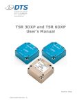
TSR PRO and TSR PRO-HB User’s Manual May 2011 13000-60160-MAN (Rev. 0) TSR PRO and TSR PRO-HB User’s Manual May 2011 Table of Contents DTS Support .................................................................................................... 3 Introducing the TSR PRO and TSR PRO-HB Shock Recorders .......................... 4 Overview of TSR Features ............................................................................... 4 Triaxial Accelerometer ................................................................................... 5 Temperature Sensor ...................................................................................... 5 DB15F Interface/Communications.................................................................... 5 Power/Charging Requirements ........................................................................ 5 Using External Power ................................................................................. 5 Status (STS) LED .......................................................................................... 6 Magnet and Motion Sensor Options .................................................................. 6 Basic Care and Handling ................................................................................. 6 Shock Rating ................................................................................................ 7 Mounting Considerations............................................................................. 7 Thermal Considerations ................................................................................. 7 TSR Control 2 Software ................................................................................... 7 Software Installation ..................................................................................... 7 Communicating with the TSR .......................................................................... 8 Initializing the TSR to Collect Data................................................................... 9 Downloading Data ........................................................................................10 Viewing Data ...............................................................................................11 Exporting Data ............................................................................................12 Real Time Mode ...........................................................................................12 Appendix A: Connector Information ............................................................. 13 Appendix B: Mechanical Specifications......................................................... 14 Appendix C: Tadiran TL-5903 Data Sheet ..................................................... 15 [email protected] ii 13000-60160-MAN (Rev. 0) TSR PRO and TSR PRO-HB User’s Manual May 2011 DTS Support TSR PRO and TSR PRO-HB shock recorders are designed to be reliable and simple to operate. Should you need assistance, DTS has support engineers worldwide with extensive product knowledge and test experience to help via telephone, e-mail or onsite visits. The best way to contact a DTS support engineer is to e-mail [email protected]. Your e-mail is immediately forwarded to all DTS support engineers worldwide and is typically the fastest way to get a response, particularly if you need assistance outside of normal business hours. For assistance by telephone, please go to http://dtsweb.com/support/techsupport.php to find the phone number appropriate for your region of the world. This manual supports the following products: 13000-60160: TSR PRO 50 g Shock Recorder (primary) 13000-60161: TSR PRO 50 g Shock Recorder (rechargeable) 13000-60170: TSR PRO 250 g Shock Recorder (primary) 13000-60171: TSR PRO 250 g Shock Recorder (rechargeable) 13000-60190: TSR PRO-HB 500 g Shock Recorder (primary) 13000-60191: TSR PRO-HB 500 g Shock Recorder (rechargeable) 13000-60210: IDR (Incident Data Recorder); 250 g (primary) [email protected] 3 13000-60160-MAN (Rev. 0) TSR PRO and TSR PRO-HB User’s Manual May 2011 Introducing the TSR PRO and TSR PRO-HB Shock Recorders The TSR PRO and TSR PRO-HB shock recorders are rugged data recorders with an integrated three-axis accelerometer and temperature sensor. The TSR is an ultra-lowpower system that permits unattended monitoring of shock and vibration events. When armed, the TSR waits in a ready state to record any event where the specified acceleration threshold is exceeded. It then returns to the ready state to wait for the next event. Overview of TSR Features • • • • • • • • • • Rated for 500 g dynamic testing environments. Internal, three-axis accelerometer with factory set ranges of ±50 or ±250 g (TSR PRO) and ±500 g (TSR PRO-HB). Internal 1 GB flash for >2 hours of data at maximum sampling rate. Records internal temperature, date and time for each event. 16-bit ADC. Both models are available with either an integrated, rechargeable battery (rechargeable) or user-replaceable, non-rechargeable battery (primary). Available 6-36 VDC external power input uses internal battery as back-up. Programmable level trigger from 2 to 10% of full scale. All communication signals and power/battery charging are supported via the DB15F interface. Integrated thru holes for mounting. TSR PRO (primary) (rechargeable also available) [email protected] TSR PRO-HB (rechargeable) (primary also available) 4 13000-60160-MAN (Rev. 0) TSR PRO and TSR PRO-HB User’s Manual May 2011 Triaxial Accelerometer The TSR PRO and TSR PRO-HB are supplied with an integrated, three-axis, MEMS accelerometer with DC response (300 Hz for TSR PRO; 1650 Hz for TSR PRO-HB). If you are unsure what range your TSR supports, this information is available from within the software via the Diagnostics window. Temperature Sensor The TSR PRO and TSR PRO-HB are supplied with an integrated temperature sensor. A single sample temperature measurement is recorded for each event. There are no user-selectable settings for the temperature sensor. DB15F Interface/Communications All communication signals and power/battery charging are supported via the DB15F interface. A TSR-to-USB communication/power cable (DTS P/N 13000-60130) is provided with your unit. Information on installing the software, initializing the TSR, downloading and viewing data is given below. See Appendix A for connector information and pin assignments. Power/Charging Requirements The TSR contains either an integrated, rechargeable battery or a user-replaceable, non-rechargeable battery sufficient to operate the unit for extended periods. Non-Rechargeable (primary) Battery Rechargeable Battery Capacity/Type 900 mAh lithium 3.6 V, 2400 mAh lithium AA cell 3 months 6 months Replace N/A. Do not remove the battery; these units are not user-serviceable. User replaceable with Tadiran TL-59032 or similar Charge Always charges when connected to USB (via AC or DC); ~4.5 hours from complete discharge to full charge. N/A. These units are not rechargeable. 1 Battery life LED (1 Hz) = charging = full charge = battery low = battery low3 1 2 3 Depends significantly on operating mode and use conditions. Data sheet can be found as Appendix C. Unit will shut down automatically to prevent overdischarge. Using External Power When external power is connected, the internal battery functions as a back-up power source. Should primary power be lost, the back-up battery will support data collection [email protected] 5 13000-60160-MAN (Rev. 0) TSR PRO and TSR PRO-HB User’s Manual May 2011 until primary power is restored or until the internal battery discharges completely and the unit shuts down. See Appendix A for connector information and pin assignments. Status (STS) LED This LED is green, blue or red and is on, off or blinking. • Green (blinking once per second): Battery is charging (rechargeable units only) • Green (solid): Battery is fully charged (rechargeable units only) • Green (short flashes): USB communication in progress • Blue (solid): Impact event/data recording in progress • Blue (blinking increasingly fast): Arming/sensor warm-up • Blue (during arming): Preparing flash memory • Red (blinking): Battery low • Red (solid): Hardware error WARNING: Do not perform any critical tests when the LED indicator is blinking red (battery low). Magnet and Motion Sensor Options The TSR includes a magnet sensor and motion sensor to aid in power savings for certain applications. The magnet sensor can detect the presence of a magnet in close proximity to the TSR. This sensor is used to allow the TSR to go into a deep sleep when the magnet is absent or fully prepare for data acquisition when the magnet is present. When the magnet is integrated into the TSR mounting scheme, the TSR will automatically prepare itself for data collection once installed. The motion sensor detects very small levels of vibration and motion. When the TSR is motionless for an extended period, it can go into a deep sleep to preserve battery life. When motion is detected it will wake and prepare itself for data collection. Should you wish to implement these capabilities, please contact DTS Technical Support for assistance. Basic Care and Handling The TSR is a precision device designed to operate reliably in dynamic testing environments. Though resistant to many environmental conditions, care should be taken not to subject the unit to harsh chemicals, submerge it in water, or drop it onto any hard surface. [email protected] 6 13000-60160-MAN (Rev. 0) TSR PRO and TSR PRO-HB User’s Manual May 2011 WARNING: Electronic equipment dropped from desk height onto a solid floor may experience as much as 10,000 g. Under these conditions, damage to the exterior and/or interior of the unit is likely. The TSR is supplied with calibration data from the factory. DTS recommends annual recalibration to ensure that the TSR is performing within factory specifications. With the exception of the user-replaceable (primary) battery, the TSR is not userserviceable and should be returned to the factory for service or repair. When not in use or if shipping is required, we suggest that you always place the unit in the padded carrying case originally provided with your unit. Shock Rating The TSR is rated for 500 g (survivable to 2,000 g), 1 ms duration, in all axes and can be mounted directly on a vehicle, sled or other dynamic testing device. Mounting Considerations The unit should be securely bolted to the test article or dynamic testing device to provide the best shock protection. Mounting methods and hardware selection should be carefully calculated to withstand expected shock loading. (See Appendix B for the TSR’s mechanical specifications.) Thermal Considerations The TSR is an extremely low power device with negligible self-heating and it is unlikely that self-heating will be an issue in real-world testing. Should you have any questions about using the TSR in your environment, please contact DTS. TSR Control 2 Software Software Installation 1. Locate the TSR Control 2 Setup.exe file on the CD or USB drive provided. Note: If you do not have the TSR Control 2 install file, please contact [email protected]. 2. Double-click the file to begin the installation and follow the prompts. Note: For Windows® XP systems, you may be asked to locate the .NET driver. When prompted, you will need to BROWSE to C:\DTS\TSR Control 2\Drivers. [email protected] 7 13000-60160-MAN (Rev. 0) TSR PRO and TSR PRO-HB User’s Manual May 2011 3. When you see this screen, installation is complete. Installation will add icons to your desktop, a quick launch toolbar, and TSR Control to your start menu programs. 4. Start TSR Control by double-clicking the desktop C:\DTS\TSR Control 2 and find the TSR Control 2.exe file. icon or go to Communicating with the TSR 5. Connect the PC to the TSR using the supplied cable. (The TSR can be connected to the PC before or after starting the software.) [email protected] 8 13000-60160-MAN (Rev. 0) TSR PRO and TSR PRO-HB User’s Manual May 2011 6. Your screen will look one of two ways, depending on whether the TSR is connected when the software is started. no TSR connected TSR connected Initializing the TSR to Collect Data 1. Click Initialize button. Choose the recording time (seconds) and trigger threshold (g) for each channel. For this version of software, the sampling rate is fixed at 10 ksps/channel. (Initializing the TSR synchronizes its timestamp with the PC.) [email protected] 9 13000-60160-MAN (Rev. 0) TSR PRO and TSR PRO-HB User’s Manual May 2011 2. After clicking OK, a dialog box will indicate that the system is armed. You can then disconnect the TSR from the PC. The LED will flash blue for ~30 seconds while it is in its arming and sensor warm-up phase. When the LED goes dark, the unit is armed. The TSR will trigger and collect data for the programmed period if the g threshold on any axis is met. The system will automatically rearm for another event after the previous event recording is complete. Downloading Data 1. Reconnect the TSR to the PC using the supplied cable. 2. The software will ask if you want to disarm the TSR. Click Yes. The TSR must be disarmed before you can download the data. 3. Click the Download button. Depending on the length of the test, it may take several minutes or longer to download the data. A progress bar is shown in the bottom right corner of the screen. 4. You can download multiple events if more than one is stored in the TSR. You can select which events to download or download them all. (Data is available for repeated download until the unit is reinitialized.) [email protected] 10 13000-60160-MAN (Rev. 0) TSR PRO and TSR PRO-HB User’s Manual May 2011 Viewing Data 1. From the screen, click the Review tab. Available data sets for viewing are shown on the left. These data sets are stored on your PC, not the TSR. 2. To Zoom, you must first select the zoom icon on the upper right of the screen. You can then use the mouse to draw a window around the data you wish to zoom in on. 3. Three data channels can be viewed on the graph at one time. You can choose which channels to view with the upper left controls. [email protected] 11 13000-60160-MAN (Rev. 0) TSR PRO and TSR PRO-HB User’s Manual May 2011 4. The data can be viewed unfiltered or with a -3 dB filter point from the pick list. An FFT on the data can also be performed. Exporting Data All data is stored in CSV file formats that can be read by Microsoft Excel® or other programs. Data is stored in the C:\DTS\TSR Control 2\Data directory under the serial number for TSR recorder. Real Time Mode To view data from the channels real time, click the Realtime tab. You can view any or all of the three channels. Note that the data is being sampled continuously at a relatively low sample rate. For example, you may not see a short duration data pulse when hitting the TSR against a surface. [email protected] 12 13000-60160-MAN (Rev. 0) TSR PRO and TSR PRO-HB User’s Manual May 2011 Appendix A: Connector Information 15-pin interface connector (DB15F) 5 10 15 1 6 11 (panel view) Pin Function 1 USB_DP 2 +Status output contact closure, normally open (maximum external voltage 36 VDC, 30 mA) 3 +Event output (5 V, 30 mA maximum relative to pin 13) 4 +Event input (maximum external voltage 7 V) 5 Ground 6 Ground 7 +VDC input (6-36 V range) 8 USB_PWR 9 +External event1 10 Reserved 11 USB_DM 12 -Status output 13 -Event output 14 -Event input 15 Ground 1 Most configurations do not support external event power. For more information, please contact DTS Technical Support. [email protected] 13 13000-60160-MAN (Rev. 0) TSR PRO and TSR PRO-HB User’s Manual May 2011 Appendix B: Mechanical Specifications Weight: ~240 g (~8.5 oz) [email protected] 14 13000-60160-MAN (Rev. 0) MODEL TL-5903 International size reference: AA, ER14505 TECHNICAL DATA (Typical values @+ 25ºC for batteries stored for one year or less) Nominal capacity 2.4 Ah Rated voltage 3.6 V Maximum recommended continuous current 100 mA Maximum pulse current capability 200 mA Weight 18 g (0.635 oz) Volume 8 cc Operating temperature range -55 ºC to +85 ºC Li metal content approx. 0.65 g U.L. Component Recognition, MH 12193 Volts DISCHARGE CHARACTERISTICS @ +25ºC 4.0 3.5 3.0 2.5 2.0 100 Ω ~31 mA (1.70 Ah) 1.5 680 Ω ~5 mA (2.17 Ah) 1.8 kΩ ~2 mA (2.20 Ah) 12 kΩ ~0.3 mA (2.17 Ah) 40 kΩ ~90 µA (2.12 Ah) 147 kΩ ~25 µA (1.90 Ah) TERMINATIONS & ORDERING NO. 1.0 1 Volts 10 100 1000 10000 VOLTAGE VS. TEMPERATURE 100000 Hours 15-5903-21500 SUFFIX- /T SOLDER TABS 15-5903-31500 SUFFIX- /P AXIAL PINS 15-5903-41500 SUFFIX- /PT2 RADIAL PINS 15-5903-36500 SUFFIX- /TP POLARIZED TABS 15-5903-52500 SUFFIX- /PT POLARIZED TABS 15-5903-53500 CAPACITY VS. CURRENT Ah 3.7 SUFFIX- /S STANDARD 2.2 -30 °C 10 µA 3.5 1.9 40 µA 3.3 0.3 mA 1.6 2 mA 3.1 1.3 2.9 1.0 0.7 31 mA 2.5 -50 55 °C 72 °C 10 mA 2.7 25 °C 0.4 -30 -10 10 30 50 70 90 ºC 0.01 0.1 1 10 mA iXtra - Long Term High Performance Note: Any presentations in this data sheet concerning performance are for information purpose only and are not construed as warranties either expressed or implied, of future performance. ECN 1501879 Rev. E 01/08 Page 1 of 2 TL-5903 CELL FEATURES 3.6 V Primary lithium-thionyl chloride (Li-SOCl2) Fast voltage recovery after long term storage and/or usage High energy density High and stable operating voltage Low self discharge rate Bobbin construction Hermetic glass-to-metal-sealing Non-flammable electrolyte Volts 3.5 MAIN APPLICATIONS VOLTAGE RESPONSE AFTER STORAGE After 1 year After 2 years 3.4 After 5 years 3.3 After 10 years Utility meters (elect., water & gas) Automatic meter reading RF systems Sensors & monitoring systems Tracking systems Wireless security systems Automotive electronics Industrial electronics Ultra Low Power (ULP) 3.2 STORAGE CONDITIONS 3.1 3.0 2.9 Pulse applied: 20 mA for 1 sec Storage: RT Background current: None 2.8 Cells should be stored in a clean & dry (less than 30 % RH) area 2.7 2.6 0 200 400 600 800 1000 VOLTAGE RESPONSE Volts 3.5 VOLTAGE RESPONSE Volts 3.5 After 1 year 3.4 For updated information please visit our website www.tadiranbat.com 1200 msec After 5 years 3.4 After 1 year After 5 years After 7 years After 10 years 3.3 Pulse applied: 20 mA for 100 msec Temperature: RT Background current: 10 µA 3.2 After 2 years 3.3 Pulse applied: 20 mA for 100 msec Temperature: RT Background current: 20 µA 3.2 3.1 3.1 0 20 40 60 80 100 120 msec 0 20 40 60 80 100 120 msec iXtra - Long Term High Performance Note: Any presentations in this data sheet concerning performance are for information purpose only and are not construed as warranties either expressed or implied, of future performance. ECN 1501879 Rev. E 11/08 Page 2 of 2