1
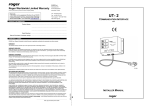
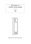
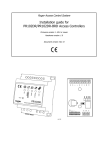
Communication Interface
UT-2USB v1.0
Installer Manual
UT-2USB v1.0 EN Rev.D.doc
2009-02-19
General
Description
The UT-2USB is a cost-effective module, that allows you to connect your serial RS485
devices (bus) to computer using a USB interface. It features various transmission rates
(half duplex) from 0 kbit/s to 115.2 kbit/s and doesn’t need any power supply. The UT2USB is delivered with 1m USB A-B cable required for communication with PC. The
connectivity with RS485 bus is carried out through screw terminals.
Although the UT-2USB converter was designed and tested for Roger Access Control
System (RACS), anyway it can be used with other applications requiring the high speed
(half duplex) serial communications port however in such cases installer must perform
adequate tests to ensure that UT-2USB will operate satisfactory in given application. UT2USB interface can be used for programming of a single PR access controller or for
management of a networked access system. Each adapter comes in a black plastic case
intended for wall mounting and has two LEDs which indicate data flow through RS485
and one LED for power supply.
The installation of UT-2USB requires two steps: first to make appropriate electrical
connections, second to install driver on PC. The UT-2USB driver creates a Virtual COM
Port (VSP-Virtual Serial Port or VCP-Virtual Com Port) within the operating system.
Properties
Power supply
The module derives the power from the USB port and doesn’t need any external power
source.
RS485 Transmission Control
The data transfer on RS485 is automatically done by the converter. Normally, the UT2USB operates in receive mode, which means that all data received by UT-2USB through
RS485 lines are shifted to PC. With the first byte of data received from PC, the UT-2USB
switches the RS485 interface (lines A and B) into transmit mode. The RS485 remains in
that mode as long as data is transmitted from PC to RS485, once the PC stops
transmission the RS485 lines returns automatically to receive mode.
RTS and CTS Lines
Generally, the RTS and CTS lines are dedicated to improve communication between
managing computer and RACS access systems which operate with CPR32-SE. The use of
RTS and CTS lines in such systems is not obligatory and may be omitted. The RTS and
CTS control lines are mostly used with access networks containing 16 or more
controllers. When used, both lines must be connected to adequate input and output of
the CPR32-SE network controller.
Note: The RTS and CTS control lines are supported by PR Master v4.3 and CPR32-SE
v3.0 or higher.
Electrically, the RTS and CTS lines are adjusted to CPR32-SE v3.0 I/O standards (RTS
active state is represented by ground voltage level, whereas line voltage above ~4,5 V or
line floating keeps line inactive).
Strona 2 z 12
UT-2USB v1.0 EN Rev.D.doc
2009-02-19
LED Indications
LED
Symbol
Color
Function
POWER
Amber
Power supply
TXD
Green
Data send to RS485 comm. bus
RXD
Red
Interface
Data received from RS485 comm. bus
Installation
Firstly, a driver installation is required within the operating system to create Virtual COM
Port. The UT-2USB interface should be connected to the PC USB port only after driver
installation (drivers can be download from www.roger.pl ).
The UT-2USB supports Windows 98, Me, XP, VISTA, Windows Server 2003, Linux (kernel
2.4.20 or later), Apple Mac OS 8, 9, Mac OS X.
Install the interface in a dry area, all electrical connections should be carry out while
interface is unplugged from the USB port. For connection with PC use the USB A-B cable
(delivered with package).
Note: Do not modify USB A-B cable, it is not allowed to cut this cable or extend it with
help of others wires inappropriate for USB transmission. It is allowed to use a special
USB extension cord, but the total USB cable length may not be longer than 5 meters.
The UT-2USB can be connected to RS485 communication bus in any, arbitrary selected,
location. The topology of RS485 communication bus in RACS system is free and may
incorporate tree, star or any combination of them. Also, no terminating resistors are
required on the ends of communication bus. Please note, that distance between UT-2USB
and CPR control panel or any controller may not exceed 1200m.
Extending Communication Distance
The UT-2USB may be used for successful communication on distances up to 1200m.
When longer distance is required a UT-3 interface can be used. The use of two UT-3
interfaces creates communication link and extends communication distance by next
1200m. For communication between access networks or controllers located in different
buildings or cities the UT-4 interface can be used. The UT-4 interface enables
communication with access controller(s) or access networks through 100/10BaseT
Ethernet network with TCP/IP communication protocol.
Connection Terminals Assignments
Name
Function
CTS line to CPR32-SE network controller (optional for PR Master 4.3)
RTS
RTS line to CPR32-SE network controller (optional for PR Master 4.3)
A
B
GND
For RACS
CTS
SHLD
Strona 3 z 12
RS485 interface, line A
RS485 interface, line B
RS485 interface, ground
RS485 cable shield
UT-2USB v1.0 EN Rev.D.doc
2009-02-19
Technical Specification
Power supply
5 VDC direct from USB Port
Average current consumption
40 mA
Operating temp. range
0...+55º C.
Communication speed
0-115.2 kbit/s
Max. communication distance for
5 meters
USB
Max. communication distance for
1200 meters
RS485
Relative humidity
10 to 95% (without condensation)
Dimensions
68 x 45 x 23 mm
Weight
~ 35g
Ordering
UT-2USB
Interface with black plastic case, 1m USB A-B cable
History
UT-2USB v1.0
Initial product version
The symbol of a crossed-through waste bin on wheels means that the product
must be disposed of at a separate collection point. This also applies to the
product and all accessories marked with this symbol. Products labeled as such
must not be disposed of with normal household waste, but should be taken to
a collection point for recycling electrical and electronic equipment. Recycling helps to
reduce the consumption of raw materials, thus protecting the environment.
Contact
Roger sp. j.
82-416 Gościszewo
Gościszewo 59
Tel.: 055 272 0132
Fax: 055 272 0133
Strona 4 z 12
UT-2USB v1.0 EN Rev.D.doc
Strona 5 z 12
2009-02-19
UT-2USB v1.0 EN Rev.D.doc
Strona 6 z 12
2009-02-19
ROGER Sp.j.
Gosciszewo 59,
RMA Form
82-416 Gosciszewo,
pomorskie, Poland
Tel.: +48 55 272 0132
Please note:
In the unlikely event you experience difficulties with your
ROGER product, please contact ROGER’s Technical
Support Department to resolve the problem.
They may be reached at +48 55 2670126 or
[email protected] Monday through Friday 8:00 A.M. to
4:00 P.M. (GMT + 1). You can also contact the Technical
Support Department by fax at +48 55 2720133.
If it is determined that you need to return the product, the
following procedure must be followed to ensure prompt
service.
Fax: +48 55 272 0133
Tech. Support: +48 55 267 0126
http://www.roger.pl
RMA no.
_______________________________
Customer information:
Company Name: …………………………………………
Contact Name: …………………………………………..
Street: …………………………………………………….
Code, City: ……………………………………………….
Country: …………………………………………………..
E-mail: …………………………………………………….
Contact phone: …………………………………………..
Fax: ………………………………………………………..
Product information:
Fault description:
Product Name: …………………………………………
what does not work, what is the reason for
complaint, what can ROGER do for you ?
Serial Number: ………………………………………..
Date of Purchase: …………………………………….
……………………………………….…….……..…..
...………………..……………………………..……
……….….………..…………….……..…….…..……
Reason for return:
……………….……………..…………………………
Warranty repair:
……….…………..………….……….……….………
Repair:
………………..……………..……....………………
Complaint:
…………………..…….……………........................
Wrong delivery:
………………………………………...…….………
Others: …………………………………………….
…….…………………………..…..…………………
………………………………………………………
(please specify)
Please note:
In the unlikely event you experience difficulties with your
ROGER product, please contact ROGER’s Technical
Support Department to resolve the problem.
They may be reached at +48 55 2670126 or
[email protected] Monday through Friday 8:00 A.M. to
4:00 P.M. (GMT + 1).
You can also contact the Technical Support Department by
fax at +48 55 2720133.
If it is determined that you need to return the product, the
following procedure must be followed to ensure prompt
service.
1. Any product returned to ROGER must have an RMA number. ROGER will refuse any package
that is returned without a valid RMA number.
2. ROGER products cannot be returned for any reason other than defective
3. Defective products will only be accepted in accordance with the ROGER`s warranty requirements.
4. All RMA numbers will be valid for a period of not longer than 14 days.
Any package send to ROGER after 14 days of issuance will be refused and shipped back to you
at additional cost.
5. If you purchased Roger product not directly from Roger company, please return it to the place
where you bought it.
6. In order to receive RMA number please fill out the following form.
7. Once the completed form has been received and processed it will be returned to you with a RMA
number appended. This is your authority to return the product.
8. Please ensure that this document accompanies the product when it is returned and that a copy is
retained such that you can refer to it when requesting an update on the progress of a repair.
9. Use one RMA number per one returned product.
10. Put your RMA number on the shipping/address label
11. Please make sure that you always return product in appropriate packaging together with a RMA
form in order to avoid damages during transit, You are advised to get proof of delivery
12. Some repairs may be chargeable and you will receive formal advice if this is the case.
13. If product returned as defective is found not to be defective, it will be returned back to the
customer at his expenses. In that case the customer will be also charged with costs which may
arise after triggering the RMA procedure.
14. If the product is beyond economical repair then the following options will be given:
Scrapped – This will occur automatically if ROGER does not receive a reply to three notices send to
the customer at least in 5 days interval.
(There may be some exceptions to this) or if you instruct us during these communications.
Returned – However this will incur shipping charges.
Note: All repairs are dealt with as rapidly as possible although repair time is not guaranteed. Please
contact us and we will try our best to suggest an estimated lead-time.
Notes
No.
1.
2.
3.
4.
5.
Fault description
Date of repair
(filled out by the customer)
(filled out by the
service)
ROGER Sp.j.
Roger Worldwide Limited Warranty
(valid only with proof of purchase and when completely fulfilled)
Please note:
In the unlikely event you experience difficulties with your ROGER
product, please contact ROGER’s Technical Support Department
to resolve the problem. Call us from Monday through Friday 8:00
A.M. to 4:00 P.M. (GMT + 1) or send email: [email protected].
Gosciszewo 59,
82-416 Gosciszewo,
pomorskie, Poland
Tel: +48 55 272 0132
Fax: +48 55 272 0133
Tech. support: +48 55 267 0126
http://www.roger.pl
PRODUCT INFORMATION:
Product Name: ..………………..……………………….……………………………
.………………………………………………………………………
.………………………………………………………………………
Serial Number: ..….…………….…………………………………………………….
Date of Purchase, Purchase receipt: .....……………………………………………………………………
WARRANTY TERMS:
ROGER sp.j. (Roger) Worldwide Limited Warranty is applicable worldwide and supersedes any other warranty.
WARRANTY
This limited warranty extends only to the original purchaser of the Roger product.
WARRANTY DURATION
Roger warrants to You (original purchaser) that for a period of one year (the “Warranty Period”) from the date of original
purchase, limited by the end of 3 years period starting with the date of manufacture, your Roger Product will be substantially
free of defects in materials and workmanship under normal use.
WARRANTY COVERAGE
If the Product proves defective during the Warranty Period please contact Roger Technical Support. BE SURE TO HAVE YOUR
PROOF OF PURCHASE ON HAND WHEN CALLING.
If ROGER receives defective product (together with a copy of your original proof of purchase and RMA Number), ROGER will
either repair or replace parts which, under normal conditions of use and service, prove to be defective in material or
workmanship.
No charge will be made for labor or parts with respect to defects covered by this warranty, provided that the work is done by
Roger or a Roger authorized service center.
This warranty does not cover expenses incurred in the transportation, removal or reinstallation of the product, whether or not
proven defective.
Replacements or repairs furnished under this warranty are subject to the same terms and conditions of the original warranty.
EXCLUSIONS AND LIMITATIONS
This warranty does not apply if the Product (a) has been altered, except by Roger, (b) has not been installed, operated, repaired,
or maintained in accordance with instructions supplied by Roger, or (c) has been subjected to abnormal physical or electrical
stress, misuse, negligence, or accident. In addition, due to the continual development of new techniques for intruding upon and
attacking networks, Roger does not warrant that the Product will be free of vulnerability to intrusion or attack.
This warranty does not cover repair or replacement where normal use has exhausted the life of a part or instrument.
IN NO EVENT WILL ROGER BE LIABLE FOR ANY LOST DATA, REVENUE OR PROFIT, OR FOR SPECIAL, INDIRECT,
CONSEQUENTIAL, INCIDENTAL OR PUNITIVE DAMAGES, REGARDLESS OF THE THEORY OF LIABILITY (INCLUDING
NEGLIGENCE), ARISING OUT OF OR RELATED TO THE USE OF OR INABILITY TO USE THE PRODUCT (INCLUDING ANY
SOFTWARE), EVEN IF ROGER HAS BEEN ADVISED OF THE POSSIBILITY OF SUCH DAMAGES. IN NO EVENT WILL
ROGER’ LIABILITY EXCEED THE AMOUNT PAID BY YOU (original purchaser) FOR THE PRODUCT, WITH THE LIMITATION
THAT THE AMOUNT CAN NOT BE HIGHER THAN ROGER’S RECOMMENDED ENDUSER PRICE (WHICH IS AVAILABLE
ON REQUEST DIRECTLY FROM ROGER).
The foregoing limitations will apply even if any warranty or remedy provided under this Agreement fails of its essential purpose.
The terms of this warranty may not be varied by any person, whether or not purporting to represent or act on behalf of Roger.
This warranty represents the full extent of Roger’s responsibility. This warranty shall become null and void in the event of a
violation of the provisions of this limited warranty.
……………….…………………………………………………………….
Date, sign and stamp of the seller
KG/rev.05/EN
ALL IMPLIED WARRANTIES AND CONDITIONS OF MERCHANTABILITY OR FITNESS FOR A PARTICULAR PURPOSE ARE
LIMITED TO THE DURATION OF THE WARRANTY PERIOD. ALL OTHER EXPRESS OR IMPLIED CONDITIONS,
REPRESENTATIONS AND WARRANTIES, INCLUDING ANY IMPLIED WARRANTY OF NON-INFRINGEMENT, ARE
DISCLAIMED.