1
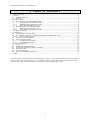
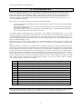
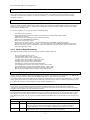
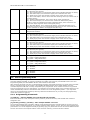
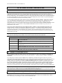
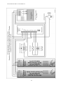
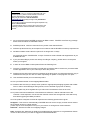
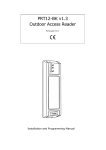
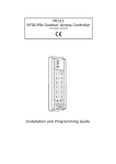
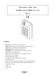
PRT42 and PRT42-BK
Indoor Access Control Terminals
Firmware v72.00
Installation and Programming Guide
PRT42 and PRT42-BK v1.0 fv72 EN Rev.C
1 TABLE
1
2
3
4
5
6
7
OF CONTENTS
Table of contents.............................................................................................................................3
General .......................................................................................................................................... 4
2.1
Designed function ..................................................................................................................... 4
2.2
Features .................................................................................................................................. 4
Operating Modes ............................................................................................................................. 5
3.1
Host-controlled Operation (ONLINE mode) ...................................................................................5
3.1.1
Wiegand Data Transmission Format ....................................................................................5
3.1.2
Magstripe Data Transmission Format ................................................................................... 6
3.1.3
RACS Data Transmission Format ......................................................................................... 6
3.2
Stand-alone Operation (OFFLINE mode)....................................................................................... 6
3.2.1
Full stand-alone operation mode ......................................................................................... 6
3.2.2
Simple stand-alone operation mode .................................................................................... 7
Installation Guidelines ......................................................................................................................8
Programming .................................................................................................................................. 9
5.1
Setting Reader Operating Mode ................................................................................................ 10
5.2
Memory Reset Procedure - Programming MASTER and INSTALLER cards ........................................ 10
5.2.1
Factory Default Settings .................................................................................................. 10
5.3
Installer Programming Mode ..................................................................................................... 10
5.4
User Programming Mode .......................................................................................................... 11
5.4.1
Programming Commands ................................................................................................. 11
5.4.2
Programming Examples ................................................................................................... 12
Stand-alone Operation ................................................................................................................... 14
6.1
Users ..................................................................................................................................... 14
6.2
ARMED and DISARMED Modes .................................................................................................. 14
6.3
Arming and Disarming of Reader (rearming)............................................................................... 14
6.4
Opening the Door .................................................................................................................... 15
6.5
Alarm Signalization ................................................................................................................. 15
6.6
Acoustic and Optical Signalization ............................................................................................. 16
Tables .......................................................................................................................................... 17
This guide applies to both PRT42 and PRT42-BK types of reader. You may program PIN codes on both version of
readers (with or without keypad) but you must be aware that you will be able to make a practical use of PINs
only if at least one of the reader (primary or secondary) will be equipped with keypad.
3
PRT42 and PRT42-BK v1.0 fv72 EN Rev.C
2 GENERAL
2.1
Designed function
The PRT42 reader have been designed for operation in access control systems to allow user identification by
using UNIQUE standard proximity cards and/or PIN codes. The reader can be configured for operation in standalone mode (called OFFLINE mode) or for use with an external access control unit (ACU) that supports a
compatible data interface formats (ONLINE mode).
When reader operate in ONLINE mode, the device functions as a slave unit serving a sole purpose of reading a
card and/or entering a PIN code and subsequent transmission of such collected data to a master unit (Access
Control Unit – ACU)) for further processing. The PRT42 terminal offers several data transmission formats for
use in ONLINE mode, which include the popular used Wiegand and Magstripe (simulation of an output of a
magnetic card reader) data protocols.
When configured for stand-alone operation (OFFLINE mode), the PRT reader will independently (i.e.
autonomously) control the supervised door access point. For this mode, the terminal offers two installation
options — one of them uses the reader’s built-in I/O signal lines as standard general purpose inputs and
outputs, the other uses them for communication with an external XM-2 I/O module and a second PRT reader
(see wiring diagrams). An access control installation containing two PRT readers (one at the entry, the other at
the exit side of the supervised gate) allows two-way passage control, while adding an XM-2 module provides
higher level of security for your whole door control system by separating its logical element (the reader) from
the actuator element controlling the door lock (i.e. door lock relay).
Note: When PRT42 reader is configured for Full Stand-alone mode it may operate with second PRT series
reader, both device can create both side (entry/exit) door control.
2.2
Features
Host-controlled mode (ONLINE mode)
26/34/42/66 bit Wiegand data format interfaces
Magstripe data format interface (ABA Track II emulation)
RACS communication interface (for ROGER PR series ACUs)
Special options for transmission of PIN codes in Wiegand data formats
LED/BUZZER control input
Stand-alone mode (OFFLINE mode)
system settings stored in nonvolatile memory
enrolment up to 120 users
user identification by card or PIN code
user indexing (ID indexed user records)
support for Door Contact (DC) and Request-To-Exit (REX) push button
Door Alarm and Door Bell outputs
Reader Disarmed Output and Ready Input for integration with security system
entry/exit door control (requires second PRT reader to form a pair)
uses built-in I/Os or remote XM-2 I/O module
4
PRT42 and PRT42-BK v1.0 fv72 EN Rev.C
3 OPERATING MODES
3.1
Host-controlled Operation (ONLINE mode)
In ONLINE mode, a PRT terminal is controlled by a master unit (ACU). The terminal handles card and/or PIN
code reading and then transmits the collected data to its master unit for further processing. A PRT terminal
offers the following communication interfaces (data transmission formats):
Wiegand 26bit
Wiegand 34bit
Wiegand 42bit
Wiegand 66bit
Magstripe (ABA Track II emulation)
RACS (Roger)
In case of Wiegand data formats there are several further settings to be configured which specify the method of
PIN code transmission technique. The RACS format is designed for use with ROGER PRxx1/PRxx2 series ACUs.
3.1.1 Wiegand Data Transmission Format
PRT Series Reader
Configured for Wiegand
Interface
DATA 1
DATA 0
IN1
CLK
DTA
When employing Wiegand transmission format, data are
transferred using sequences of pulses sent over the CLK and DTA
lines. Depending on the selected version of the transmission
format, the PRT reader uses 26, 34, 42 or 66 bits to transmit a
code read in from the presented card or a PIN entered.
Wiegand
ACU
Note: For card and PIN codes longer than the number of bits
available in the selected data transmission format a PRT reader
omits the most significant bits of the data transmitted. As a
result you may see different card number or PIN as expected.
Generally, transmission of PIN codes to ACU can be carried out in
two ways: one is to transmit the entire PIN code as one data
frame; the other is to transmit it in separate parts, each
containing a code of a single key pressed (for more details about
PIN code transmission using Wiegand formats see table 2).
When using Wiegand format, the dual color LED STATUS lights steady in RED, the LED SYSTEM is turned ON for
a moment each time the card or PIN code is read. The LED OPEN is controlled by the IN1 input line. When IN1
is shorted with supply minus the LED OPEN turns ON and the internal BUZZER sounds, when IN1 is shorted
with supply plus or left unconnected LED OPEN and BUZZER are not active.
5
PRT42 and PRT42-BK v1.0 fv72 EN Rev.C
3.1.2 Magstripe Data Transmission Format
PRT Series Reader
Configured for
Magstripe Interface
DATA
CLOCK
IN1
CLK
DTA
When employing Magstripe transmission format, data is
transferred using electric signal waves transmitted via the CLK
and DTA lines.
The terminal’s LED indicators and buzzer are controlled in the
same manner as described for the Wiegand formats (see
previous section).
In Magstripe format, the PRT reader transmits a sequence of
data bits representing either a code read in from a presented
card or digits of an entered PIN. When operating with Magstripe
format, the reader stores all pressed keys in a buffer memory
and does not transmit them, until the [#] key is pressed — a
press of the [#] key is treated by the unit as the end of entered
PIN code. The Magstripe format does not allow single digits of a
PIN code to be transmitted separately after each corresponding
key-press.
Magstripe
ACU
3.1.3 RACS Data Transmission Format
DATA
CLOCK
IN1
CLK
DTA
When employing the RACS transmission format, the PRT reader
communicates with host (ACU) over the CLK and DTA lines.
Unlike the Wiegand or Magstripe format, a PRT reader using the
RACS format is required to have an individual address (ID
numbers = 0…3), which can be set during configuration of the
reader.
When using RACS format, communication between the PRT
reader and its ACU is bilateral, this allows controller to monitor
communication. The reader’s LED indicators and buzzer are
controlled by a host unit (ACU), unless the reader has lost
communication with the host unit.
Note: When all LEDs are flashing it indicates that the reader lost
communication with host ACU unit.
PRT Series Reader
Configured for
RACS Interface
PRxx1/PRxx2 Series
ACU
Each entry of PIN code must be followed by pressing the [#]
key, which is treated as an end of PIN code.
The PRT42 readers offers F1 (Door Bell) function key, pressing this key will cause transmission of adequate
event code to host unit which may further take special action (e.g. trigger Door Bell or Light output). The host
reaction for functional keys depends of controller’s firmware and its configuration, always refer to controller’s
settings when configuring functional keys on reader.
On PRT readers which are not equipped with functional keys like F1 or F2 but are equipped with keypad, user
may press [#] key and hold-down it for two or more seconds, the host controller will treat such an action as
Door Bell or Exit Push button. The way how the controller will handle long press of [#] key depend in its
configuration and firmware.
Note: In RACS format, the IN1 input of the PRT reader is not used to control the reader LED’s (LEDs are
controlled by host unit) but is dedicated to disable reader’s operation. When IN1 is shorted with supply minus
reader will not read cards nor accept PIN codes.
3.2
Stand-alone Operation (OFFLINE mode)
The PRT series readers offer two variants of stand-alone operation: Full Stand-alone Mode and Simple Standalone Mode. In both operation modes the reader is capable of providing independent (i.e. autonomous) control
of one door passage.
3.2.1 Full stand-alone operation mode
6
PRT42 and PRT42-BK v1.0 fv72 EN Rev.C
12 V
Primary PRT Series Reader
Configured for
Full Stand-alone Mode
Secondary PRT Series Reader
Configured for
RACS Mode Address ID0
CLOCK
DATA
NO1
COM
NC1
NO2
COM
NC2
IN1
COM
IN2
IN1
CLK
DTA
IN1
CLK
DTA
IN / OUT DEVICES
XM-2 I/O Expander Module
In this mode, the reader’s CLK and DTA lines are used for communication with a remote XM-2 I/O module and,
optionally, with additional (secondary) PRT reader (to enable two-way door control). The IN1 line operates as a
programmable input. The I/O lines on the XM-2 module can be programmed to have several predefined
functions (see settings for C5, C6, C7, C8 and C9 parameters in Installer Programming Mode). The Full Standalone Operation Mode offers improved security, because it allows for separating the identification device (i.e.
the reader) from the actuator element (i.e. the relay controlling the electric lock).
The max. length of the cable run between a PRT reader and an XM-2 module or a secondary PRT reader is
limited to 150m. For two-way door control, the main reader needs to be configured in Full Stand-alone Mode,
whereas the connected to it secondary PRT reader needs to be set in RACS mode with an address set to ID=0.
Note: The XM-2 I/O expander module connected to PRT reader must be set to address ID=5 (jumpers JP1 and
JP3 closed).
3.2.2 Simple stand-alone operation mode
12 V
Input or Output
In this mode, the reader’s CLK and DTA lines are used as
standard I/O lines, the IN1 line operates as programmable input.
Each I/O line can be configured to have one of the several
available functions.
Input or Output
IN1
CLK
DTA
Input Only
Note: The CLK and DTA line may operate as input or as output,
the function assigned to CLK/DTA line automatically defines
whether the line will operate as output or as input.. If configured
to be an output, the CLK or DTA line operates as an opencollector line capable to sink up to 20 mA. If required, both lines
can be shorted and programmed to the same output function
which makes total output sink current up to 40mA.
PRT Series Reader
Configured for
Simple Stand-alone Mode
7
PRT42 and PRT42-BK v1.0 fv72 EN Rev.C
4 INSTALLATION GUIDELINES
The reader should be mounted near the supervised door on a vertical piece of supporting structure.
The power supply should be disconnected before making any electrical connections.
For installations on a metal surface place a non-metallic min. 10 mm thick spacer (a plastic plate, a
plaster plate etc.).
When using a separate power supply sources, connect all supply minuses leads together.
Roger recommends to ground the negative (–) power supply lead.
With its relatively weak electromagnetic field generation, the terminal is not expected to cause harmful
interferences to operation of other equipment, however other equipment generating interferences,
especially radio frequency emitting equipment and electron tube computer monitors, may affect card
reading.
For best results mount the proximity readers at least 0.5 m apart.
For installations with two readers to be mounted on opposite sides of the same wall and along the same
geometrical axis, place a metal plate between them and make sure none of them has direct contact with
it (at least 10 mm space is required).
Should card reading performance of the reader deteriorate (e.g. reduced reading range or incorrect
readings) in the desired mounting location, consider choosing a new installation place.
Once the reader is fixed and electrically connected it must be properly configured, the configuration
process requires Programming MASTER and INSTALLER Cards and programming Reader Operation
Mode. When device is factory new it has both: MASTER and INSTALLER card programmed and reader is
configured for RACS mode with address ID0.
The factory programmed MASTER and INSTALLER cards can be replaced by any other cards whenever
required (see Memory Reset Procedure).
The Reader Operating Mode can be changed using jumpers located on reader’s printed board, jumper
locations may be changed with power supply off.
When reader is set configured for ONLINE mode the programming of MASTER and INSTALLER cards can
be omitted.
8
PRT42 and PRT42-BK v1.0 fv72 EN Rev.C
5 PROGRAMMING
Before reader will start operation it must be configured to adequate Reader Operation Mode. When reader is set
for any of the ONLINE operating mode it doesn’t require any further programming. When reader is set for
Stand-alone Operation Mode (OFFLINE), installer must program to a reader two special cards: MASTER and
INSTALLER and then enter Installer Programming Mode and make final settings which adopt reader for
individual installation requirements. The programming of PINs and/or Cards can be done by installer or end
user in User Programming Mode.
When reader is not properly configured it may generate following signals:
No sound signals and the SYSTEM LED is ON – Microprocessor memory error, the unit must be reloaded
with new firmware.
Short beeps repeated in sequence (0.2s/0.2s) and the SYSTEM LED is ON – The Reader Operating Mode
has not been programmed.
Long beeps repeated in sequence (2s/2s) and the SYSTEM LED is ON – A MASTER and INSTALLER card
have not been programmed or the memory is corrupt.
The reader manual programming can be done either in the Installer Programming Mode or in the User
Programming Mode. To program the keypad reader you use its numeric keys. To program the no-keypad reader
a dedicated Programming Card has to be presented to the reader multiple times. For programming the unit in
the User Programming Mode, the MASTER Card is used, for programming the unit in the Installer Programming
Mode, the INSTALLER Card is used.
Note: Each User ID number contains 3 digits, only ID numbers within the 000-119 range are allowed. Any
attempt to program an existing identification tag (a card or a PIN code) will be indicated as a programming
error.
Readers that have no keypad can be programmed by multiple reading of the valid Programming Card. All
programming methods and functions described for the keypad readers are also valid for the no-keypad readers,
the only difference being that one press of a desired key on keypad reader is simulated on a no-keypad reader
by several presentations (readings) of the programming card to it. And so, to simulate on a no-keypad reader a
press of N numeric key let the reader read the programming card N times (present it to the reader and take it
back) and then wait 2..3 seconds for the reader to generate a special prompt encourage signal (♪ ♪) — this is a
prompt indicating that the reader has successfully accepted the series of card readings as a single key-press
and is ready to follow next steps of the programming procedure. Here is how to enter a digit or character
during programming on readers with no keypad:
Key
How to simulate dedicated KEY on no-keypad readers during programming
[1]
Read 1 time the valid programming card or press 1 time the BELL key.
[2]
Read 2 times the valid programming card or press 2 times the BELL key.
[3]
Read 3 times the valid programming card or press 3 times the BELL key.
[4]
Read 4 times the valid programming card or press 4 times the BELL key.
[5]
Read 5 times the valid programming card or press 5 times the BELL key.
[6]
Read 6 times the valid programming card or press 6 times the BELL key.
[7]
Read 7 times the valid programming card or press 7 times the BELL key.
[8]
Read 8 times the valid programming card or press 8 times the BELL key.
[9]
Read 9 times the valid programming card or press 9 times the BELL key.
[0]
Read 10 times the valid programming card or press 10 times the BELL key.
[*]
Read 11 times the valid programming card or press 11 times the BELL key.
[#]
Read 12 times the valid programming card or press 12 times the BELL key.
Notes: The programming of a reader can be done on primary reader only. This rule is valid to either User and
Installer programming modes. The BELL key is available on some PRT readers (e.g. PRT42-BK). When reader is
not equipped with any key programming can be entirely done only through valid programming card.
9
PRT42 and PRT42-BK v1.0 fv72 EN Rev.C
5.1
Setting Reader Operating Mode
The PRT42 reader offer two main modes of operation: ONLINE and OFFLINE (stand-alone), and enables few
other options which may modify those main operating modes. The selection of proper operating mode is
achieved on programming jumpers (for details see table 2). The reader operating mode can be changed
whenever required.
5.2
Memory Reset Procedure - Programming MASTER and INSTALLER cards
The Memory Reset Procedure erases MASTER and INSTALLER cards as well as all users programmed in reader
(clears all cards and PINs). After Memory Reset reader restores factory-shipped default settings. The Memory
Reset is used only when reader is configured for stand-alone mode, the Memory Reset doesn’t affect reader
configured for ONLINE mode.
To clear the reader’s memory go through the following steps:
Turn OFF power to the unit.
Select appropriate stand-alone mode (Full stand-alone or Simple stand-alone mode)
Install the JP1 jumper.
Restore power, the reader generates a continuous beep.
Wait until the LED OPEN starts flashing.
Open (remove) the JP1 jumper.
Present any card to the reader — this card becomes a new MASTER Programming Card.
Present any (second) card to the reader — this card becomes a new INSTALLER Programming Card.
Once the previous step is completed the reader automatically ends the memory reset procedure and
enters the operating mode.
5.2.1 Factory Default Settings
After Memory Reset reader restores the following Factory Default Settings:
Door lock triggering time: 4 sec.
Time allowed to close a door: 12 sec.
Line IN1 on the reader: Door Contact Input.
Line IN1 on the XM-2 module: Exit Button Input.
Line IN2 on the XM-2 module: Ready Input.
CLK/REL1 line function: Door Lock Output.
DTA/REL2 line function: Reader Disarmed Output.
User identification mode on the primary reader: Card or PIN.
User identification mode on the secondary reader: Card or PIN.
Option [Door Alarm Indication On Internal Buzzer]: Option OFF.
Option [Access Disabled When Reader Armed]: Option OFF.
5.3
Installer Programming Mode
Use this mode to configure various functionalities of the reader. You can enter it by presenting your INSTALLER
Card at the reader. Once in this mode LED OPEN is ON and the LED STATUS is green ON.
The reader placed in this mode waits for the installer to sequentially enter thirteen digits labelled C1…C13. After
entering the last of them the reader saves all data that has been entered, then it exits the programming mode
and returns to condition it was in before entry to installer programming.
Note: Depending on the operation mode desired for the reader (either Simple Stand-alone Mode or Full Standalone Mode), the configuration digits C5 and C6 have different effect: for Simple Stand-alone Mode they
configure the reader’s CLK and DTA internal lines, whereas for Full Stand-alone Mode they configure the REL1
and REL2 relay outputs on the XM-2 expander module.
The IN1 located on reader always operate as input, the reader’s CLK and DTA lines can be used both as inputs
and outputs, however the REL1 and REL 2 lines can function only as outputs, as well as IN1 and IN2 on XM-2
may operate as inputs only. If you try to program the REL1 and REL2 lines to input function, they will not work
at all.
Configuration Parameters in The Installer Programming Mode
Parameter
Value
Description
C1C2
00–99
C1 and C2 digits define Door Lock Triggering Time (in seconds). When set to
C1C2=00, each granted access toggles the REL1 output to opposite condition
(Toggle Operation). The Door Ajar alarm is disabled when C1C2 is set to 00.
C3C4
00–99
C3 and C4 digits define Time Allowed to Close the Door (in seconds), the C3C4 timer
starts after the Door Lock Triggering Time (C1C2) has elapsed.
10
PRT42 and PRT42-BK v1.0 fv72 EN Rev.C
C5
0–7
Function settings for the REL1 output on the XM-2 module or for the CLK line:
[0] - Not Used, line ignored;
[1] – Door Contact Input, line shorted to supply minus indicates that door is closed;
[2] – Exit Button Input, line shorted to supply minus activates door lock;
[3] – Ready Input, when line shorted to supply minus reader can be armed;
[4] – Door Lock Output, used to control the door releasing device (an electric lock or
an electric strike);
[5] – Reader Disarmed Output, line is active when reader is disarmed;
[6] – Door Alarm Output, line is active when reader has detected any alarm
situation, output is modulated according to detected alarm, when more then one
alarm exist output signalize alarm with highest priority;
[7] – Door Bell Output, line is triggered for approx. 5 seconds after BELL key is
momentary pressed or [#] key is pressed and hold-down for min. 2 seconds (this
function operates on readers not equipped with BELL key).
C6
0–7
Function settings for the REL2 output on the XM-2 module or for the DTA line,
assignments as above.
C7
0–3
Function settings for the IN1 line on the reader:
[0] - Not Used, line ignored;
[1] – Door Contact Input, line shorted to supply minus indicates that door is closed;
[2] – Exit Button Input, line shorted to supply minus activates door lock;
[3] – Ready Input, when line shorted to supply minus reader can be armed.
C8
0–3
Function settings for the IN1 line on the XM-2 module:
[0] - Not Used, line ignored;
[1] – Door Contact Input, line shorted to supply minus indicates that door is closed;
[2] – Exit Button Input, line shorted to supply minus activates door lock ;
[3] – Ready Input, when line shorted to supply minus reader can be armed.
C9
0–3
Function settings for the IN2 line on the XM-2 module:
[0] - Not Used, line ignored;
[1] – Door Contact Input, line shorted to supply minus indicates that door is closed;
[2] – Exit Button Input, line shorted to supply minus activates door lock ;
[3] – Ready Input, when line shorted to supply minus reader can be armed.
C10
0–1
Primary (main) Reader Identification Mode:
[0] - [Card or PIN] identification;
[1] - [Card + PIN] identification.
C11
0–1
Secondary (auxiliary) Reader Identification Mode:
[0] - [Card or PIN] identification;
[1] - [Card + PIN] identification.
C12
0–1
Option: Door Alarm Indication On Internal Buzzer:
[0] – Disabled;
[1] – Enabled.
C13
0–1
Option: Access Disabled When Reader Armed]:
[0] – Disabled;
[1] – Enabled.
5.4
User Programming Mode
Use the User Programming Mode to administrate users registered in the reader, as well as to add and delete
proximity badges and PINs. To enter this mode let the reader read one time your MASTER card. In the User
Programming Mode, the LED OPEN is ON and LED STATUS is ON in RED.
After entering this mode you have 12 programming functions (command sequences) to choose from (see table
below). Upon beginning any of function, the SYSTEM LED starts flashing and it keeps flashing until the
command sequence has been correctly completed by the programmer. If the reader receives no key pressed
from the programmer for more than approx. 20 s between the successive steps of the command sequence, the
reader automatically ends the command but still remains in the User Programming Mode — you may either
return to the programming process by entering a desired command anew or you may exit the programming
mode with a press of a [#] key.
5.4.1 Programming Commands
[1][PIN][#] – Add one NORMAL user with the PIN code specified
The user is stored in a first unoccupied memory location (his ID is unknown) and the PIN code entered is
assigned to him.
[2][Card#1][Card#2]...[Card#N] – Add multiple NORMAL card users
The terminal indicates each successful reading of a presented card with a prompt signal for the next one; this
function will be ended automatically if no card is presented within approx. 20 sec. from the last completed card
presentation or it can be stopped manually by pressing a [#] key. Note that the new card users added with this
function are stored in unoccupied location of the terminal’s memory, but their IDs are unknown.
11
PRT42 and PRT42-BK v1.0 fv72 EN Rev.C
[3][ID][PIN][#][Card] – Add one NORMAL user with a specified ID, PIN code and card
A new user is registered in the terminal’s memory at the ID = 000–119. Both the entered PIN code and the
presented proximity card are assigned to him. When [Card] is omitted new user is registered with ID and PIN
only.
[4][PIN][#] – Add one TOGGLE user with a specified PIN code only
The user is stored in a first unoccupied memory location (his ID is unknown) together with entered PIN code.
[5][Card#1][Card#2]...[Card#N] – Add multiple TOGGLE users with cards only
The terminal indicates each successful reading of a presented card with a prompt signal for the next one. This
function will be ended automatically if no card is presented within 30 s from the last completed card
presentation or it can be stopped manually by pressing a [#] key. Note that the new card users added with this
function are stored in unoccupied locations of the terminal’s memory, but their IDs are unknown.
[6][ID][PIN][#][Card] – Add one TOGGLE user with a specified ID, PIN code and card
A new TOGGLE user is registered in the terminal’s memory at the specified ID index. Both the entered PIN code
and the presented proximity card are assigned to him.
[7][PIN][#] – Delete a specified PIN code
The terminal finds a user with the specified PIN code and then deletes it from the terminal’s memory; the user
can still use his card if it was previously assigned to him.
[8][Card] – Delete a specified card from the terminal memory
The terminal finds a user with the specified card and then deletes it from the terminal’s memory; the user can
still use his PIN code if it was previously assigned to him.
[9][ID] – Delete a user with a specified ID index
The terminal finds a user with the specified ID and then deletes both his PIN and his card. Once completed, a
new user can be programmed to use this ID index.
[*][0] – Delete all users in the system
Deletes all users including their cards and PIN codes.
[#] – Exit the User Programming mode
Once exited from the User Programming mode, the terminal returns to this mode which it operated before
entering programming.
Note: The user ID number consist always from three digits from 000–119 range. PIN codes may be 3 to 6 digits
long and must be always followed by [#] key which marks the end of a code. An attempt to assign to a new
user ID which already is assigned for another one will remove it (the older) form memory.
5.4.2 Programming Examples
Example 1: Add a new NORMAL User, the user’s PIN should be 1234 (PIN only)
Read your MASTER card.
The reader enters User Programming Mode (the reader’s OPEN LED is ON, the reader’s STATUS LED is
ON and RED).
Press these keys on the keypad: [1] [1] [2] [3] [4] [#] [#].
The reader registers the [1234] code in its memory and then exits the programming mode and returns
to normal operation.
Or follow these steps, if the reader is not fitted with a keypad:
Read your MASTER card.
The reader enters User Programming Mode (the reader’s OPEN LED is ON, the reader’s STATUS LED is
ON and RED).
Present your MASTER card once and wait for the reader to generate a prompt signal (♪ ♪).
Present your MASTER card once and wait for the prompt signal (♪ ♪).
Present your MASTER card twice and wait for the prompt signal (♪ ♪).
Present your MASTER card thrice and wait for the prompt signal (♪ ♪).
Present your MASTER card four times and wait for the prompt signal (♪ ♪).
Present your MASTER card twelve times and wait for the prompt signal (♪ ♪).
Present your MASTER card twelve times and wait for the prompt signal (♪ ♪).
Once the reader has registered the [1234] code in its memory, it exits the programming mode and returns to
normal operating mode.
Example 2: Add a new card TOGGLE LTD User
Read MASTER card.
12
PRT42 and PRT42-BK v1.0 fv72 EN Rev.C
The reader enters User Programming Mode (the reader’s OPEN LED is ON, the reader’s STATUS LED is
ON and RED).
Do the following: Press [*] [5] (Present a new card to the reader) [#] [#]
The reader has registered the new indicated card in its memory and exited the programming mode.
Once the reader has registered the new indicated card in its memory, it exits the programming mode.
Example 3: Add a new NORMAL User with a specified ID number (ID=87) and an entered PIN code
(PIN=1234) and a presented card
Read MASTER card.
The reader enters User Programming Mode (the reader’s OPEN LED is ON, the reader’s STATUS LED is
ON and RED).
Press [3] [0] [8] [7] and wait for the reader to generate a prompt signal (♪ ♪).
Press [1] [2] [3] [4][#], present the card for the user.
Once the reader has registered the new user with an ID=87 and assigned the indicated card and the specified
PIN to him, it exits the programming mode.
Example 4: Delete a user by using his ID=45
Read MASTER card.
The reader enters User Programming Mode (the reader’s OPEN LED is ON, the reader’s STATUS LED is
ON and RED).
Press [9] [4] [5] [#].
The reader deletes the user with ID=45 from its memory, however, it remains in the programming mode, which
allows you to use your next desired programming command.
Example 5: Rearm the reader by presenting a TOGGLE User card
Read your TOGGLE User card; once accepted the reader grants you access and its SYSTEM LED starts
blinking.
With the SYSTEM LED blinking, once more present your TOGGLE card.
The reader changes its arming state (the STATUS LED will change illumination color).
Note: If the Access Disabled When Reader Armed option is enabled and the reader is in ARMED state, then in
order to gain access first you will have to switch the reader to DISARMED state (by presenting twice the
TOGGLE card) and only then use your identification tag once again to open the door.
Example 6: Rearm the reader by entering a TOGGLE User PIN code
Key in the TOGGLE User PIN code; once accepted the reader grants you access and its SYSTEM LED
starts blinking.
With the SYSTEM LED blinking, once more key in the TOGGLE User PIN code.
The reader changes its arming state from ARMED to DISARMED or vice versa (the STATUS LED will change
illumination color).
Example 7: Rearm the reader when the [Card + PIN] verification mode is enabled
Present your TOGGLE User card to the reader then key in the TOGGLE User PIN code; once accepted the
reader grants you access and its SYSTEM LED starts blinking.
With the SYSTEM LED blinking, once more present your TOGGLE card and then key in the PIN.
The reader changes its arming state from ARMED to DISARMED or vice versa (the STATUS LED will change
illumination color).
13
PRT42 and PRT42-BK v1.0 fv72 EN Rev.C
6 STAND-ALONE OPERATION
6.1
Users
In the stand-alone mode, a PRT reader can register up to 120 users, each with a card, a 3 to 6 digit long PIN
code and an ID number (000–119). The PRT reader precludes assignment of the same code or card to 2
different users. Users enter their PIN codes keyed in with a press of the [#] key ([#] key is required to mark
the end of PIN entry). User identification is done by verifying the PIN code entered or the card presented. When
an option [Card+PIN] set users must present his card and subsequently enter its PIN. The [Card+PIN] option
can be set separately for primary and secondary reader.
The PRT reader supports five types (classes) of users: INSTALLER, MASTER, NORMAL, TOGGLE and TOGGLE
LTD. The INSTALLER and MASTER Users are dedicated for programming purpose only. NORMAL Users are
authorized to unlock the supervised door, but not to arming and disarming reader. TOGGLE Users are
authorized both to unlock the system-supervised door and to switch reader between ARMED-DISARMED modes.
TOGGLE LTD Users are authorized to change ARMED-DISARMED mode of the reader only, they are not
authorized for door unlock.
A new user can be registered in the device following either a simple or a full programming procedure. The
simple procedure consists in programming a PIN code or a card into the system without specifying the ID
number of a user to whom the programmed PIN/card will belong — so the system simply stores the code
entered/card presented in a unoccupied ID user number. The full programming procedure requires you to
specify an ID number for the new user being programmed which has to be followed by entering his PIN code
and presenting his card.
Note: When you program user using full programming procedure you will be able later to selectively delete a
user simply by specifying his ID number, so you do not need to know his card or PIN code.
User Types (User Classes)
6.2
INSTALLER
A card of this user allows you to enter Installer Programming Mode. INSTALLER
user has no PIN code.
MASTER
A card of this user allows to enter User Programming Mode. MASTER user has no
PIN code.
NORMAL
Users of this type are solely authorized to unlock the door. They can use a card
or a PIN code.
TOGGLE
Users of this type have the authorization to unlock the door and to control the
ARMED-DISARMED state of the reader. They can use a card or a PIN code.
TOGGLE LTD
Users of this type are solely authorized to control the ARMED-DISARMED state of
the reader. They can use a card or a PIN code.
ARMED and DISARMED Modes
In the standalone mode, the reader can be in any of the operational states, either ARMED or DISARMED. Its
current state is indicated by the reader’s dual color LED STATUS — it lights in RED for ARMED or GREEN for
DISARMED.
The change of the reader’s state to ARMED can be additionally indicated through the output line (for this,
enable the Reader Disarmed Output setting). Such configuration allows the output line to be used as a driver to
arm/disarm a connected alarm system or to switch on/off some other auxiliary system or device such as
heating, lights etc. In general, the reader’s ARMED-DISARMED states has no effect on unlocking door, unless
the Access Disabled When Reader Armed option has been enabled (see C13 digit in Installer Programming
Mode). With this option activated, access to the supervised room is granted only when the reader is disarmed.
Use of the reader’s configuration option mentioned above makes TOGGLE Users capable of enable/disable
access to the supervised room; and it allows automatic access locking upon a reader entering the ARMED state.
Note: Upon powering on, the reader automatically returns to the ARMED/DISARMED state it was in before
power off. Also, the reader restores its original ARMED/DISARMED state after exiting the programming mode.
After erasure of the reader’s memory the reader always returns to ARMED state
6.3
Arming and Disarming of Reader (rearming)
The action that changes the reader’s state from ARMED to DISARMED and vice versa will be referred to as
REARMING, the term “arming” should be understood as switching the reader into the ARMED state, and the
term “disarming” as switching the reader into the DISARMED state.
14
PRT42 and PRT42-BK v1.0 fv72 EN Rev.C
Reader rearming operation can be done by TOGGLE or TOGGLE LTD Users. The action needed by a TOGGLE
user to rearm the reader is to read twice the TOGGLE card or to enter twice the TOGGLE PIN code — however,
when reader operates with the Card+PIN mode activated, user needs to do both things, read a card and enter a
PIN. TOGGLE LTD users may rearm the reader simply by a single use of their identification tag (Card, PIN or
both when Card+PIN option is active).
If the reader operates with input line defined as Ready Input the arming of a reader can be carried out only
when this input remains in active condition, when such a input is not triggered (passive state) every attempt to
arm reader will be rejected. Usually the Ready Input should be connected to the Alarm System Control Unit’s
output which is intended to indicate that the Alarm System is ready for arming (Ready Output on an Alarm
System Control Unit).
6.4
Opening the Door
In order to open the door user must present its card, enter its PIN or do both things when Card+PIN mode is
active. Each time card is read or key is pressed reader activates orange LED SYSTEM and generates short beep.
After successful identification reader activates door lock for predefined time (see Installer Programming Mode,
C1 and C2 digits which define Door Lock Triggering Time). The activation of a lock is signalized on green LED
OPEN, this led remain ON as long as door lock is energised. When access to room is denied reader generates
long beep. The access to a room can be disabled in two situations:
When Card or PIN is unknown or
When reader operates in ARMED mode and has set an option: Access Disabled When Reader Armed
If the second scenario occurs the TOGGLE or TOGGLE LTD. user may use its identifier (Card, PIN or both when
Card+PIN mode is active) to switch reader from ARMED to DISARMED mode thus enabling NORMAL users to
open the door or may switch reader from DISARMED to ARMED mode in order to disable NORMAL users to open
the door.
6.5
Alarm Signalization
The PRT reader may signalize three type of alarms: Door Forced, Prealarm and Door Ajar. The alarm
signalization is carried out on dedicated output line (Alarm Output) and optionally on internal buzzer (see
option: Door Alarm Indication on Internal Buzzer). Each alarm is signalized in different way (see table
below). Duration of alarm, regardless of its type is ~3 minutes. An alarm can be stopped within 3 minutes time
from its start by entering any identification tag (Card or PIN) registered in the reader. The Door Ajar alarm is
immediately stopped, once the door is closed. If more than one alarm is triggered, the reader indicates the
alarm with the highest priority. The Forced Entry and Door Ajar alarms may occur only if the reader operates
with a door open sensor.
Alarm Signalization on Output and/or Buzzer
Alarm type
Priority
Indication method
Alarm situation
Door
Forced
High
In cycles with the following sequence: Active 4 sec., Pause - 4 sec.
Door opened without use of valid
card or PIN.
4s
4s
Prealarm
Medium
In cycles with the following sequence: Active 1 sec., Pause - 1 sec.
1s
Detection of 3 consecutive
attempts to enter an unregistered
(unknown) card or PIN code.
1s
Door Ajar
Low
In cycles with the following sequence: Active 1 sec., Pause - 1 sec., Active - 1 sec., Pause
- 5 sec.
15
After access has been granted
and door opened it is left ajar for
the time exceeding the door open
time setting (see C2C3 parameter
in Installer Programming Mode).
PRT42 and PRT42-BK v1.0 fv72 EN Rev.C
1s
5s
1s
6.6
Acoustic and Optical Signalization
Acoustic Signals in Stand-alone Operation Mode
Indication
Symbol
Description
One long signal
♫
Error indication, unknown card or PIN, access denied.
Two long signals
♫ ♫
Attempt to assign the same function to two different
output lines.
Three beeps
♪♪♪
Command successfully completed (OK Signal).
Two series of three
beeps
♪♪♪ ♪♪♪
Signal OK repeated two times - reader restarted.
Two short signals
♪♪
Prompt (encourage) signal, the reader is waiting for the
next part of the command being entered. This signal is
intended to encourage the programmer to enter next
programming steps.
One long signal
continuously
repeated
♫
♫
♫
♫ … and so on
Memory error or MASTER or INSTALLER cards not
programmed - memory reset necessary. This signal is
accompanied by LED SYSTEM steady ON.
Legend:
♫ - one long signal
♪ - One short signal (beep)
LED Indications in Stand-alone Operation Mode
STATUS
LED
OPEN LED
SYSTEM
LED
Meaning
Green
—
—
The reader is in DISARMED state now.
Red
—
—
The reader is in ARMED state now.
Red
Green
—
The reader is in User Programming Mode.
Green
Green
—
The reader is in Installer Programming Mode.
—
—
Orange
Flashing
Waiting for a user to enter the next part of a command or
programming function.
—
—
Orange,
one flash
A user card has been read or a user PIN entered.
—
Green
—
Door lock is activated, the LED remains active as long as door lock is
triggered.
—
Green
flashing
—
The reader is waiting for a user to enter his PIN code.
—
—
steady
The reader has detected some problem (Memory contents is
corrupted or the MASTER/INSTALLER card are not programmed).
16
PRT42 and PRT42-BK v1.0 fv72 EN Rev.C
7 TABLES
Table 1: Reader Operating Modes
Code
Operating Mode
Description
OFFLINE MODE
SIMPLE Stand-alone Mode
The reader operates in a stand-alone mode, the CLK and
DTA lines serve as ordinary I/O lines.
OFFLINE MODE
FULL Stand-alone Mode
The reader operates in a stand-alone mode, the CLK and
DTA lines are used to communicate with remote XM-2
I/O module set to address ID=5 and optional secondary
PRT reader set to address ID=0.
ONLINE MODE
RACS Communication Interface
Address ID=0
The reader operates in Host-controlled mode, it needs to
be connected to a PR series access controller.
ONLINE MODE
RACS Communication Interface
Address ID=1
The reader operates in Host-controlled mode, it needs to
be connected to a PR series access controller.
ONLINE MODE
RACS Communication Interface
Address ID=2
The reader operates in Host-controlled mode, it needs to
be connected to a PR series access controller.
ONLINE MODE
RACS Communication Interface
Address ID=3
The reader operates in Host-controlled mode, it needs to
be connected to a PR series access controller.
ONLINE MODE
MAGSTRIPE Communication
Interface
The reader operates in Host-controlled mode, it needs to
be connected to a master unit (ACU) which requires
Magstripe data format.
ONLINE Mode
26 bit WIEGAND Communication
Interface
The reader operates in Host-controlled mode, it needs to
be connected to a master unit (ACU) which requires 26
bit Wiegand data format.
ONLINE Mode
34 bit WIEGAND Communication
Interface
The reader operates in Host-controlled mode, it needs to
be connected to a master unit (ACU) which requires 34
bit Wiegand data format.
ONLINE Mode
42 bit WIEGAND Communication
Interface
The reader operates in Host-controlled mode, it needs to
be connected to a master unit (ACU) which requires 42
bit Wiegand data format.
ONLINE Mode
66 bit WIEGAND Communication
Interface
The reader operates in Host-controlled mode, it needs to
be connected to a master unit (ACU) which requires 66
bit Wiegand data format.
Note 1: For Wiegand data interfaces the JP1 and JP2 jumpers are used to specify the method of PIN code
transmission (for coding details see table 2 below). In the stand-alone mode (OFFLINE mode) the JP1 jumper
is used to enter the Memory Reset Procedure. In RACS data formats the JP1 and JP2 jumpers are used to
specify reader’s address (ID number).
Note 2: For both Simple and Full stand-alone modes the JP1 jumper is used to initialize the Memory Reset
Procedure.
17
PRT42 and PRT42-BK v1.0 fv72 EN Rev.C
Table 2: PIN Transmission Options for Wiegand Interfaces
JP1 and JP2
Description
Details
1 to 10 keys long
PIN, transmitted in
BCD format
Each key pressed on the reader's keypad is buffered and the
transmission starts only after pressing the [#] key indicating end of
code. The PIN code keyed in is transmitted as a BCD coded number.
1 to 12 keys long
PIN, transmitted in
binary format
Each key pressed on the reader's keypad is buffered and the
transmission starts only after pressing the [#] key indicating end of
code. The PIN code keyed in is transmitted as a binary number.
Each key
transmitted
separately with
two control bits
Each key pressed on the reader's keypad is immediately transmitted
to the master controller unit as a sequence of 6 bits (EXXXXP) where
XXXX represents the code of the pressed key supplemented by two
control bits (E and P), each controlling half of the transmission
stream. This format is compatible with HID 5355 series readers,
option: With Parity.
Each key
transmitted
separately, no
control bits added
Each key pressed on the reader's keypad is immediately transmitted
to the master controller unit as a sequence of 4 bits (XXXX) which
represent the code of the pressed key. This format is compatible
with HID 5355 series readers, option: Without Parity.
Note: The PIN code transmission options described in this table apply only to Wiegand26/34/42/66bit data
communication formats.
Table 3: Technical Specification
Input voltage
10...16 V DC
Current consumption
Avg. 60 mA
Anti-sabotage feature (Tamper output)
Transistor output, 20mA max. sink current at 16V max.
Reading distance
Up to 12 cm for ISO cards – depending on card type, card supplier
and card quality
Proximity cards
EM UNIQUE 125 kHz, ASK modulation, 64 bits (compatible with
EM4100/4102)
Distance to ACU when in online mode or
to XM-2 and secondary PRT reader
when in off line mode
150 m
Environmental class
(according to EN 50131-1)
Class I, Indoor
temp.: +5°C +40°C
Relative humidity: RH 10 to 95% (non-condensing)
Ingress protection
IP 30
Dimensions
45 X 151.5 X 20.5
Weight
~90g
Approvals
CE
18
PRT42 and PRT42-BK v1.0 fv72 EN Rev.C
Table 4: Connection Terminals
Full
Stand-alone
Operation Mode
Networked Mode
Can be configured to
be used as an input
or an output
CLOCK
communication line
DATA 0 line for Wiegand formats
CLOCK for Magstripe and RACS formats
DTA
Can be configured to
be used as an input
or an output
DATA
communication line
DATA 1 line for Wiegand formats
DATA for Magstripe and RACS formats
IN1
In stand-alone modes this line functions as
an electric input and it can be configured to
several available functions.
TAMP
Tamper switch, NC contacts, 24V/50mA.
Label
Simple
Stand-alone
Operation Mode
+12V
Supply input plus
GND
Supply input minus
CLK
In Wiegand and Magstripe formats, the IN1
line activated by shorting it with the
negative lead (–) of power supply. When
IN1 is triggered it turns the OPEN LED to
ON and also activates acoustic signal on the
internal buzzer.
Table 5: Ordering Codes
PRT42
RFID/PIN reader, black
PRT42-BK
RFID reader, black
PRT42 Grey
RFID/PIN reader, light grey
PRT42-BK Grey
RFID reader, light grey
RM-2
Relay module. The RM-2 offers two relays with one NO/NC contact
5A/24V rated, relay contacts protected with overvolatge elements.
XM-2
I/O expander module, digital communication with host unit, two inputs
and two relay outputs, each relay output offers one NO/NC contact
5A/24V rated. Relay contacts protected with overvoltage elements.
Table 6: Product History
Hardware
Firmware
Date
Description
PRT42 v1.0
71.00
18/04/05
The initial product version.
PRT42 v1.0
72.00
05/07/05
Error signalization modified.
The symbol of a crossed-through waste bin on wheels means that the product must be
disposed of at a separate collection point. This also applies to the product and all
accessories marked with this symbol. Products labeled as such must not be disposed of with
normal household waste, but should be taken to a collection point for recycling electrical
and electronic equipment. Recycling helps to reduce the consumption of raw materials, thus
protecting the environment.
Contact information:
Roger sp. j.
82-416 Gościszewo
Gościszewo 59
Phone: 055 272 0132
Fax: 055 272 0133
e-mail: [email protected]
19
PRT42 and PRT42-BK v1.0 fv72 EN Rev.C
Site name:
ID Number
Master
Installer
0.
1.
2.
3.
4.
5.
6.
7.
8.
9.
10.
11.
12.
13.
14.
15.
16.
17.
18.
19.
20.
21.
22.
23.
24.
25.
26.
27.
28.
29.
30.
31.
32.
33.
34.
35.
36.
37.
38.
39.
40.
41.
42.
43.
44.
45.
46.
47.
48.
49.
50.
51.
52.
53.
54.
55.
56.
57.
58.
59.
60.
61.
62.
63.
Card number
USER LIST
Reader location:
PIN
Type
-
20
User Name
PRT42 and PRT42-BK v1.0 fv72 EN Rev.C
Site name:
ID Number
64.
65.
66.
67.
68.
69.
70.
71.
72.
73.
74.
75.
76.
77.
78.
79.
80.
81.
82.
83.
84.
85.
86.
87.
88.
89.
90.
91.
92.
93.
94.
95.
96.
97.
98.
99.
100.
101.
102.
103.
104.
105.
106.
107.
108.
109.
110.
111.
112.
113.
114.
115.
116.
117.
118.
119.
120.
Card number
USER LIST
Reader location:
PIN
Type
21
User Name
PRT42 and PRT42-BK v1.0 fv72 EN Rev.C
22
PRT42 and PRT42-BK v1.0 fv72 EN Rev.C
23
PRT42 and PRT42-BK v1.0 fv72 EN Rev.C
25
PRT42 and PRT42-BK v1.0 fv72 EN Rev.C
26
ROGER Sp.j.
Gosciszewo 59,
Roger Worldwide Limited Warranty
Please note:
In the unlikely event you experience difficulties with your ROGER
product, please contact ROGER’s Technical Support Department
to resolve the problem.
They may be reached at +48 55 2670126 or [email protected]
Monday through Friday 8:00 A.M. to 4:00 P.M. (GMT + 1).
You can also contact the Technical Support Department by fax at
+48 55 2720133.
82-416 Gosciszewo,
pomorskie, Poland
Sales Dept.: +48 55 272 0134
Technical Support: +48 55 267 0126
Purchase Dept.: +48 55 267 0127
FAX: +48 55 272 0133
e-mail: [email protected]
PRODUCT INFORMATION:
Product Name: ..………………..……………………….……………………………
.………………………………………………………………………
.………………………………………………………………………
Serial Number: ..….…………….…………………………………………………….
Date of Purchase, Purchase receipt: .....……………………………………………………………………
WARRANTY TERMS:
ROGER sp.j. (Roger) Worldwide Limited Warranty is applicable worldwide and supersedes any other warranty.
WARRANTY
This limited warranty extends only to the original purchaser of the Roger product.
WARRANTY DURATION
Roger warrants to You (original purchaser) that for a period of one year (the “Warranty Period”) from the date of original
purchase, limited by the end of 3 years period starting with the date of manufacture, your Roger Product will be substantially
free of defects in materials and workmanship under normal use.
WARRANTY COVERAGE
If the Product proves defective during the Warranty Period please contact Roger Technical Support. BE SURE TO HAVE YOUR
PROOF OF PURCHASE ON HAND WHEN CALLING.
If ROGER receives defective product (together with a copy of your original proof of purchase and RMA Number), ROGER will
either repair or replace parts which, under normal conditions of use and service, prove to be defective in material or
workmanship.
No charge will be made for labor or parts with respect to defects covered by this warranty, provided that the work is done by
Roger or a Roger authorized service center.
This warranty does not cover expenses incurred in the transportation, removal or reinstallation of the product, whether or not
proven defective.
Replacements or repairs furnished under this warranty are subject to the same terms and conditions of the original warranty.
EXCLUSIONS AND LIMITATIONS
This warranty does not apply if the Product (a) has been altered, except by Roger, (b) has not been installed, operated, repaired,
or maintained in accordance with instructions supplied by Roger, or (c) has been subjected to abnormal physical or electrical
stress, misuse, negligence, or accident. In addition, due to the continual development of new techniques for intruding upon and
attacking networks, Roger does not warrant that the Product will be free of vulnerability to intrusion or attack.
This warranty does not cover repair or replacement where normal use has exhausted the life of a part or instrument.
ALL IMPLIED WARRANTIES AND CONDITIONS OF MERCHANTABILITY OR FITNESS FOR A PARTICULAR PURPOSE ARE
LIMITED TO THE DURATION OF THE WARRANTY PERIOD. ALL OTHER EXPRESS OR IMPLIED CONDITIONS,
REPRESENTATIONS AND
WARRANTIES, INCLUDING ANY IMPLIED WARRANTY OF NON-INFRINGEMENT, ARE DISCLAIMED.
IN NO EVENT WILL ROGER BE LIABLE FOR ANY LOST DATA, REVENUE OR PROFIT, OR FOR SPECIAL, INDIRECT,
CONSEQUENTIAL, INCIDENTAL OR PUNITIVE DAMAGES, REGARDLESS OF THE THEORY OF LIABILITY (INCLUDING
NEGLIGENCE), ARISING OUT OF OR RELATED TO THE USE OF OR INABILITY TO USE THE PRODUCT (INCLUDING ANY
SOFTWARE), EVEN IF ROGER HAS BEEN ADVISED OF THE POSSIBILITY OF SUCH DAMAGES. IN NO EVENT WILL
ROGER’ LIABILITY EXCEED THE AMOUNT PAID BY YOU (original purchaser) FOR THE PRODUCT, WITH THE LIMITATION
THAT THE AMOUNT CAN NOT BE HIGHER THAN ROGER’S RECOMMENDED ENDUSER PRICE (WHICH IS AVIABLE ON
REQUEST DIRECTLY FROM ROGER)
The foregoing limitations will apply even if any warranty or remedy provided under this Agreement fails of its essential purpose.
The terms of this warranty may not be varied by any person, whether or not purporting to represent or act on behalf of Roger.
This warranty represents the full extent of Roger’s responsibility. This warranty shall become null and void in the event of a
violation of the provisions of this limited warranty.
ROGER Sp.j.
Gosciszewo 59,
RMA Form
82-416 Gosciszewo,
pomorskie, Poland
Sales Dept.: +48 55 272 0134
Please note:
In the unlikely event you experience difficulties with your
ROGER product, please contact ROGER’s Technical
Support Department to resolve the problem.
They may be reached at +48 55 2670126 or
[email protected] Monday through Friday 8:00 A.M. to
4:00 P.M. (GMT + 1).
You can also contact the Technical Support Department by
fax at +48 55 2720133.
If it is determined that you need to return the product, the
following procedure must be followed to ensure prompt
service.
Technical Support: +48 55 267 0126
Purchase Dept.: +48 55 267 0127
FAX: +48 55 272 0133
e-mail: [email protected]
RMA no.
_______________________________
Customer information:
Company Name: …………………………………………
Contact Name: …………………………………………..
Street: …………………………………………………….
Code, City: ……………………………………………….
Country: …………………………………………………..
E-mail: …………………………………………………….
Contact phone: …………………………………………..
Fax: ………………………………………………………..
Product information:
Fault description:
Product Name: ……………………………………………
Serial Number: ………………………………………......
what does not work, what is the reason for
complaint, what can ROGER do for you ?
Date of Purchase: ……………………………………….
……………………………………….…….……..…..
...………………..……………………………..……
Reason for return:
……….….………..…………….……..…….…..……
……………….……………..…………………………
Warranty repair:
……….…………..………….……….……….………
Repair:
………………..……………..……....………………
Complaint:
…………………..…….……………........................
Wrong delivery:
………………………………………...…….………
Others: …………………………………………………
…….…………………………..…..…………………
…………………………………………………………..
(please specify)
Please note:
In the unlikely event you experience difficulties with your
ROGER product, please contact ROGER’s Technical
Support Department to resolve the problem.
They may be reached at +48 55 2670126 or
[email protected] Monday through Friday 8:00 A.M. to
4:00 P.M. (GMT + 1).
You can also contact the Technical Support Department by
fax at +48 55 2720133.
If it is determined that you need to return the product, the
following procedure must be followed to ensure prompt
service.
1. Any product returned to ROGER must have an RMA number. ROGER will refuse any package
that is returned without a valid RMA number.
2. ROGER products cannot be returned for any reason other than defective
3. Defective products will only be accepted in accordance with the ROGER`s warranty requirements.
4. All RMA numbers will be valid for a period of not longer than 14 days.
Any package send to ROGER after 14 days of issuance will be refused and shipped back to you
at additional cost.
5. If you purchased Roger product not directly from Roger company, please return it to the place
where you bought it.
6. In order to receive RMA number please fill out the following form.
7. Once the completed form has been received and processed it will be returned to you with a RMA
number appended. This is your authority to return the product.
8. Please ensure that this document accompanies the product when it is returned and that a copy is
retained such that you can refer to it when requesting an update on the progress of a repair.
9. Use one RMA number per one returned product.
10. Put your RMA number on the shipping/address label
11. Please make sure that you always return product in appropriate packaging together with a RMA
form in order to avoid damages during transit, You are advised to get proof of delivery
12. Some repairs may be chargeable and you will receive formal advice if this is the case.
13. If product returned as defective is found not to be defective, it will be returned back to the
customer at his expenses. In that case the customer will be also charged with costs which may
arise after triggering the RMA procedure.
14. If the product is beyond economical repair then the following options will be given:
Scrapped – This will occur automatically if ROGER does not receive a reply to three notices send to
the customer at least in 5 days interval.
(There may be some exceptions to this) or if you instruct us during these communications.
Returned – However this will incur shipping charges.
Note: All repairs are dealt with as rapidly as possible although repair time is not guaranteed. Please
contact us and we will try our best to suggest an estimated lead-time.