1
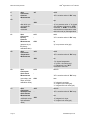
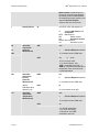
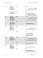
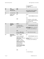
KPSI Digital Series ® User’s Manual Series 351, 353 & 355 Series 500 & 501 Toll Free: 800 • 328 • 3665 order online: www.LEVELandPRESSURE.com A U G U S T 2 0 11 Measurement Specialties ® KPSI Digital Series User’s Manual Ta b l e o f C o n t e n ts Introduction ............................................................................................................................. 1 Product Introduction................................................................................................................ 2 Cabling and Wiring.................................................................................................................. 3 Installation............................................................................................................................... 6 Operation ................................................................................................................................ 7 Nomenclature.......................................................................................................................... 7 Setting the Address................................................................................................................. 8 Verifying the Address and Operation ...................................................................................... 9 Command (Functional Overview) ........................................................................................... 9 Making a Measurement ........................................................................................................ 10 Starting a non-concurrent measurement (m[v] command).............................................. 11 Starting a Concurrent Measurement (C[v] command) .................................................... 12 Measurement command variations ................................................................................. 13 Other non-concurrent measurements ............................................................................. 14 Other concurrent measurements .................................................................................... 15 Changing the Units ............................................................................................................... 16 Setting user units .................................................................................................................. 17 Configuring the Averaging Time ........................................................................................... 18 Alphabetic Command Reference .......................................................................................... 19 Calibration............................................................................................................................. 27 Troubleshooting and Maintenance........................................................................................ 28 Troubleshooting .............................................................................................................. 28 Maintenance.................................................................................................................... 29 General Maintenance Tips.................................................................................................... 29 Clogged nose piece or dirty diaphragm .......................................................................... 29 Cleaning your transducer ................................................................................................ 29 Warranty and Product Return Procedures............................................................................ 31 Warranty.......................................................................................................................... 31 Merchandise return procedures ...................................................................................... 31 Page 1 www.Meas-Spec.com Measurement Specialties ® KPSI Digital Series User’s Manual Introduction t h a n k y o u f o r y o u r p u r c h a s e The KPSI digital line of water level transducers offers accuracy, versatility and extensive features. You’ve made a commitment to quality. In return, we promise a high level of service and support to help you get the most from your investment in leading-edge environmental monitoring instrumentation. a b o u t k p s i® t r a n s d u c e r s September 2010, Measurement Specialties, Inc. (NASDAQ: MEAS), a global designer and manufacturer of sensors and sensor-based systems, announced the acquisition of Pressure Systems, Inc. (“PSI”). Measurement Specialties will continue to develop, manufacture and service highly accurate level measuring instruments for environmental applications. We are committed to consistently meeting and exceeding our customers’ expectations. w e b s i t e a n d e - m a i l You can visit our website at www.Meas-Spec.com for information on our latest product releases, application notes, product specifications and certifications, and IS control installation drawings. We also welcome your questions and comments and strive to reply promptly. Please e-mail us at [email protected]. t e c h n i c a l s u p p o r t While this manual provides extensive guidance for everything from setup through maintenance, we understand that there’s nothing like getting an expert on the phone to provide quick answers and help address challenges for your particular application. If you have questions concerning any of our products, call (757) 865-1243 or 1-800-328-3665 Monday through Friday between 7:30 a.m. and 5:30 p.m. Eastern Standard Time. o r d e r i n g p r o d u c t s a n d a c c e s s o r i e s For your convenience, orders may be placed on-line by visiting our e-commerce website, www.LevelandPressure.com. You can also contact our Customer Service department at 1-800328-3665 or contact your local Measurement Specialties representative. Expedited shipping is available. Manual Content Disclaimer This user’s manual was prepared for the current firmware and software releases at the time of the manual publication. While this document is believed to be thoroughly reliable, Measurement Specialties assumes no liability for inaccuracies. Addenda will be distributed as deemed necessary by Measurement Specialties. All computer programs supplied with your products are written and tested on available systems at the factory. Measurement Specialties assumes no liability for other computers, languages, or operating systems. Measurement Specialties reserves the right to change the specifications without notice. Any questions regarding firmware upgrades may be addressed to Applications Engineering. Application software and transducer firmware revisions as well as manual addenda may be obtained from www.meas-spec.com. Page 2 www.Meas-Spec.com Measurement Specialties ® KPSI Digital Series User’s Manual Product Introduction The KPSI® 500 Series and KPSI® 350 Series SDI-12 submersible pressure transducers use an isolated diaphragm sensor that is specifically designed for use with hostile fluids and gases. The sensor uses a silicon pressure cell that has been fitted into a stainless steel or titanium package with an integral, compliant stainless steel or titanium barrier diaphragm. Different user-installable nose caps are available for the KPSI 500 Series transducer. The closed-face end cap with #8-32UNC-2B threaded hole is best used where weights are required and for those installations where users may encounter sharp, protruding objects. The open-face end cap that allows maximum contact with the liquid media is ideal for wastewater and “greasy” applications where clogging of the sensor is a concern. A high density “piezometer” screen may be inserted into specially-drilled open-face end caps should the user decide to completely cover the KPSI 500 Series transducer with soil or silt. Page 3 www.Meas-Spec.com Measurement Specialties ® KPSI Digital Series User’s Manual Cabling and Wiring Most installations using the transducer connect our polyurethane or Tefzel® cable to a junction box. From this junction box, users run their own cable to the required instrumentation. Polyurethane is used for most applications while Tefzel® is recommended for highly corrosive environments. The transducers are intended for applications with requirements that include battery-powered operation with minimal current drain, low system cost, and use of a single recorder with multiple sensors attached. It will accommodate cable lengths between sensors and recorder up to 200 feet. The vented cable termination end is prepared at the factory to eliminate future moisture migration down its length. It may be noticed where the lead wires emerge from under the jacket, that potting material plus a shrink tube “boot” have been added. Every effort should be made to leave this feature intact. Should the cable be longer than is needed for your installation, it is recommended that the excess length be accommodated in a service loop and that the potted end of the cable NOT be shortened. The cable attached to your transducer is specifically engineered for submersible applications. The outer jacket provides long term reliability under most conditions. The cable should be handled carefully, however, as the jacket may be subject to cutting should it be “raked” over extremely sharp edges. To guard against water incursion should an inadvertent cut occur, we have incorporated an exclusive “water block” feature immediately beneath the jacket. This feature makes the cable “self-sealing” in all but the most extreme cases. The cable is fully shielded, with the shield connected to the metal housing at the transducer end and terminated in a blue-insulated wire at the termination end. The shield should always be terminated to a good earth ground, unless the transducer is installed in an area where electrolysis corrosion is known to be a serious problem. Surge/lightning protection is offered as an option for your transducer. This is achieved through the use of two (2) separate protectors. One is located in a 4-inch long housing extension attached directly to the non-pressure-sensing end of the transducer. The other protector is located at the surface and grounded via a DIN-rail or ground wire. Whether lightning protection is employed or not, the cable shield is left exposed (as mentioned previously) so that the shield may be attached to an earth ground. sdi-12 wiring Only three wires are needed to use the SDI-12 interface. A fourth wire (cable shield — blue) is added for user convenience. 1. 2. 3. Page 4 Serial data (white) — SDI-12 interface between sensors and data recorders. Ground (black) — Supply return and earth ground. Supply (red) — This line is internally regulated and can accept 8-28 VDC. www.Meas-Spec.com Measurement Specialties Page 5 ® KPSI Digital Series User’s Manual www.Meas-Spec.com Measurement Specialties ® KPSI Digital Series User’s Manual Installation The transducers are designed for rugged use; however, they need protection from overpressure and sharp impact. They are designed to be used in a vertical orientation with the sensing diaphragm facing downward. For greatest accuracy, re-calibrations should be performed with the transducer in this position. When lowering the transducer into a liquid, penetrate the surface slowly and only to the depth necessary. Avoid dropping the unit from above the surface. Clean the transducer’s surface by rinsing it in a mile detergent. Direct probing of the diaphragm or attempts to remove protective screens will damage the sensor and void the warranty. Most users either suspend the transducer in a perforated 1-inch or 2-inch PVC instrumentation free well or attach the transducer using our optional ½-inch MNPT to a rigid conduit. Some applications use our optional mounting bracket (PN 49-06-00PC) to clamp the transducer to a fixed object (i.e., wall, ladder, step). Alternatively, because our cable has a 200 pound pull strength, the transducer may be suspended without any protective still well, mounting clamp, or supporting cables. However, users often use our cable hanger. This sensor (device) slides onto the cable from the bare wire end. The cable hanger may be positioned anywhere on the cable by pushing the ends together. Once positioned, the cable hanger contracts to provide a snug grip. Page 6 www.Meas-Spec.com Measurement Specialties ® KPSI Digital Series User’s Manual Operation Your transducer was shipped from the factory preset to address 0 (zero), and with the pressure units set to those requested in your order. However, if modifications are required for your application, you should familiarize yourself with the steps and commands needed to alter the setup of the transducer. To issue commands to the sensor via SDI-12, you will need to connect it to a data recorder that is capable of issuing standard and extended SDI-12 commands. Nomenclature All commands have three components: the sensor address, the command body, and the command termination. The sensor address is a single character and is the first character of a command. In the examples that follow, it is usually the number 0 (the default address as shipped from the factory). The command body and the responses are shown as a combination of upper and lower case letters. The upper case letters are the fixed portions of the command the lower case letters are the variables or values. In the specific examples, you will see that the lower case letters are replaced with actual numbers. All commands are shown with an exclamation point (!) as the command terminator. Page 7 www.Meas-Spec.com Measurement Specialties ® KPSI Digital Series User’s Manual Setting the Address If you are using the sensor connected to common wiring with other SDI-12 sensors, you may need to change the default sensor address. Otherwise, skip this section. A unique address assigned to each sensor is an absolute requirement for multiple sensors to share the same wiring. When the data recorder needs data from a particular sensor, it requests data using a particular address. Only the sensor with the matching address can reply. Two or more sensors with same address replying will garble this reply. The factory default SDI-12 address (0) is best reserved only for single sensors operating alone on dedicated wiring. using the get/set sensor address commands No other SDI-12 sensors connected to the system should be set to address 0 or to the desired sensor address. Hint: If you do not know the address of a particular sensor, first use the Get Unknown Address command to have the sensor identify itself. Its syntax is as follows: ?! NOTE: There can be only one SDI-12 sensor connected to common wiring in order for the Get Unknown Address command to work. The SDI-12 command for changing a sensor’s address is “A” (Set Sensor Address). aAn! Where “a” is the current address of the sensor, “n” is the new SDI-12 address Valid addresses are 0 to 9, A to Z, a to z. The sensor will issue a reply message in response to the command, if the command was recognized. The message will be the new address “n.” Note that both commands above follow the SDI-12 standard of ending with a “!”terminator. As an example, the following Set Sensor Address command would set the sensor address from 0 to 5: 0A5! The sensor will respond with the new address, which is “5.” Subsequently, the address can be set to a different address, 9 for example, by the command: 5A9! Page 8 www.Meas-Spec.com ® Measurement Specialties KPSI Digital Series User’s Manual Ve r i f y i n g t h e A d d r e s s a n d O p e r a t i o n The tables below are sample commands and responses for the KPSI500 Other models have the same response for their respective model. The sensor will respond with an identifying message when it receives the Identify command “I.” The format of the command is: aI! Where “a” is the address for the sensor The sensor will reply with: a13-KPSI---500---hhh-ssssss-vvv Where: “a” is SDI-12 address “13” is SDI protocol version (read 1.3) “KPSI” is Brand Name “500" is KPSI Model Number “hhh” is Hardware revision level “ssssss” is Sensor serial number (up to 8 char.) “vvv” is Software version If you do not get a reply, check the address setting for the sensor and make sure you use the proper address. Command (Functional Overview) The commands to set up and operate the sensor are those defined by the SDI-12 specifications Version 1.0, Version 1.1, Version 1.2, and Version 1.3, plus extended commands. Note: ALL SENSOR COMMANDS ARE UPPER CASE. All commands start with a single character address and end in an exclamation point. The address is a single character with values 0 to 9, A to Z, or a to z. Values are entered in the form of a polarity sign (+ or -) followed by up to seven digits, including a decimal point. The commands are in ASCII and all the replies use printable ASCII characters followed by <CR> <LF>. The case of the letters is important. An “A” is not the same as an “a.” The sensor replies to all SDI commands it supports. If the sensor receives a command it does not support, no reply is made. The reply (response) will have one of three forms: a0000 Page 9 Where “a” is sensor address and 0000 indicates that no further message to be sent. www.Meas-Spec.com Measurement Specialties atttn : a atttnn ® KPSI Digital Series User’s Manual Where “a” is sensor address, “ttt” is time (in seconds) sensor needs to make the measurement or process command, and “n” is the number of data values (limited to 9) that may be fetched by the Get Data (“D0”) command when data is ready. In this older form, the sensor responds a second time with its address “a” when the data is ready (if “ttt” was not 000). This second response is called a Service Request response. This format is generated by older non-concurrent measurement commands (see “M[v]” commands below) and other older commands. Where “a” is sensor address, “ttt” is time (in seconds) sensor needs to make the measurement or process the command and “nn” is the number of data values that may be fetched by the Get Data (“D0”) command when data is ready. This newer response format (in SDI Version 1.2 and later) does not generate the second Service Request response and can return a larger number of values (“nn”) limited to 99. This format is generated by a newer concurrent measurement commands (see “C[v]” commands below). If you issued the Change Sensor Address command or the Identify command described in the previous sections, you already have some experience with using commands. There are other commands available to make measurements, set the type of output units for the measurements, perform special scaling of the measurements, do field calibration, and the like. The following sections describe the commands by function. Making a Measurement There are two classes of measurement commands which will be referred to as Start NonConcurrent Measurement (“M[v]”) commands) and Start Concurrent Measurement (“C[v]”) commands). In the first class the data recorder issues the measurement command and then waits for the sensor to complete the measurement before continuing the data collection cycle. Only one sensor can be accessed at a time and a maximum of nine parameters can be returned. With Version 1.2 of the specification, concurrent measurements are permitted. With a concurrent measurement, the data recorder can request the sensor to take a measurement, determine how long it will be until the sensor has a reading, and then continue making requests to other sensors on the SDI-12 bus. This way, multiple sensors are taking measurements concurrently. Once the measurement time for a sensor expires, the data recorder polls that sensor for its data. Page 10 www.Meas-Spec.com Measurement Specialties ® KPSI Digital Series User’s Manual starting a non-concurrent measurement (M[v] command) The original command to tell the sensor to start a measurement non-concurrently is: aM[v]! Where “a” is the address character, and “M[v]” is a Start Non-Concurrent Measurement command. An optional digit “v” identifies command variations. Most data recorders will issue this command and automatically handle the reply to collect data. You can also issue the command yourself. In reply, the sensor will respond with: atttn Acknowledges it is from sensor with address “a”, that “ttt” seconds are required before the measurement is completed, and “n” values will appear in final data stream acquired. When the measurement is complete, the sensor sends a second response, called a Service Request: a Where Service Request response contains only “a,” the address of the sensor. Note that you still have no data from the sensor. To get data, enter the Get Data command to sensor: aD0! Where “a” is the address character and “D0” is the command to retrieve measured data. Note: The number zero follows “D,” not the letter “O”. Depending on the variation of the command, the sensor will reply with one of these response formats: av avu avvv Where “a” is the address, “v” is a data value, and “u” is an optional units indicator. Both “v” and “u” have the format of a polarity sign (+ or -) followed by up to seven digits, including a decimal point. Format returned depends on the command variation. The “u” indicates the units of the measurement according to the following tables: 0 units are feet of water 1 units are psi 2 units are kilopascal 3 units are cm of water 4 units are meters of water 5 units are mm of water 9 units depend on user-entered scale factors (slope and offset). Page 11 www.Meas-Spec.com ® Measurement Specialties KPSI Digital Series User’s Manual If the field calibration offset is non-zero, then one of the following values of “u” will be returned: 10 units are feet of water with non-zero field calibration offset 11 units are psi with non-zero field calibration offset 12 units are kilopascal with non-zero field calibration offset 13 units are cm of water with non-zero field calibration offset 14 units are meters of water with non-zero field calibration offset 15 units are mm of water with non-zero field calibration offset 19 user units with non-zero field calibration offset (psi + field calibration offset) * user slope + user offset set by XE or XS set by XUU set by XUU If the unit has had its calibration modified at a standards lab other than at Measurement Specialties, then the value returned for “u” will have one hundred (100) added to it. In other words, if the “XC” command has been utilized to set the calibration scale factor (slope) to other than 1 or the calibration offset factor to other than 0, then 100 will be added to the unit’s indicator. Starting a Concurrent Measurement (C[v] command) The command to tell the sensor to start a concurrent measurement is: aC[v]! Where “a” is the address character, and “C[v]” is a Start Concurrent Measurement command. An optional digit “v” identifies command variations. In reply, the sensor will respond with: atttnn Acknowledges it is from sensor with address “a”, that “ttt” seconds are required before the measurement is completed, and “nn” values will appear in final data stream acquired. Note the 2-digit “nn” returned allows for a larger number of data items to be returned in the eventual data response (though not utilized by model 500 sensor). When the measurement is complete, the sensor does NOT issue the second response, known as a Service Request response, as did an “M” command. To request the data you must enter the Get Data command only after the first response’s estimated time for completion (ttt) has expired: aD0! Where “a” is the address character and “D0” is the command to retrieve measured data. Note: the number zero follows D, not the letter “O”. As in all of the other (non-CRC) “M” and “C” commands, a “D0” command must eventually be issued to get the data from the sensor. In its response, three data measurements and a CRC appendage are returned as follows: a+3.14+2.718+1.414Ipz Page 12 where (“Ipz”) is the three-character CRC code appendage. www.Meas-Spec.com Measurement Specialties ® KPSI Digital Series User’s Manual Depending on the variation of the command, the sensor will reply with one of these response formats: av avu avvv Where “a” is the address, “v” is a data value, and “u” is an optional units indicator. Both “v” and “u” have the format of a polarity sign (+ or -) followed by up to seven digits, including a decimal point. Format returned depends on the command variation. measurement command variations To enhance the error detection capability in SDI-12 data collection systems, variations of the Start Non-Concurrent Measurement commands (M, M1 ... M9) and Start Concurrent Measurement commands (C, C1, ...C9) are available. One variation requests that the data be returned with a 16-bit Cyclic Redundancy Check (CRC) appended. It adds a “C” to command, such as MC, MC1, CC, or CC1 The number of measurements returned in response is the same as the measurements returned for a non-CRC command, but with a CRC appendage following them. An example of such a command follows: aMC! Where “a” is the address character, “M” is a basic command to make a measurement, and “C” is the added command letter requesting a CRC appendage. The sensor might respond with: a0053 Acknowledging it is at address “a” and indicating that after 5 seconds, three (3) measurements will be ready to read with “D0” command. When an “M”command measurement is complete, the sensor responds with an extra Service Request response. a Page 13 Where “a” is the address character. www.Meas-Spec.com ® Measurement Specialties KPSI Digital Series User’s Manual As in all of the other (non-CRC) “M” and “C” commands, a “D0” command must eventually be issued to get the data from the sensor. In its response, three data measurements and a CRC appendage are returned as follows: a+3.14+2.718+1.414Ipz where (“Ipz”) is the three-character CRC code appendage. other non-concurrent measurements The SDI standard allows for several other measurement command variations, such as “M1,” “M2,” and the like. The sensor supports the following ones: aM1! Measure psi using factory calibration. Does not apply user scaling, field calibration, or offsets. Returns 1 value and the units are fixed to psi. aM2! Measure temperature (Celsius or Fahrenheit). This returns two values: the temperature and the units. The units will be 0 for Celsius and 1 for Fahrenheit. aM3! Measure scale factors: user slope, user offset, and field calibration offset. Use this if you want to view user-entered values that can affect the value returned. aM4! Measure calibration lab slope and offset. Use this if you want to view the calibration lab values that can affect the value returned. aM5! This command requests high accuracy PCB (printed circuit board) temperature. aM6! This command requests battery voltage. aM7! This command combines M0 and M2 for both pressure and temperature. Remember to issue the “D0” command after the measurement is complete (as signaled by extra Service Request response), in order to retrieve the data. Page 14 www.Meas-Spec.com Measurement Specialties ® KPSI Digital Series User’s Manual other concurrent measurements The SDI standard allows for other concurrent measurement commands, such as “C1,” “C2,” etc. The sensor supports the following optional concurrent measurements commands: aC1! Measure psi using factory calibration. Does not apply user scaling, field calibration, or offsets. Returns 1 value and the units are fixed to psi. aC2! Measure temperature (Celsius or Fahrenheit). This returns two values: the temperature and the units. The units will be 0 for Celsius and 1 for Fahrenheit. aC3! Measure user scale factors: user slope, user offset, field calibration offset. Use this if you want to view user-entered values that can affect the value returned. aC4! Measure calibration lab slope and offset. Use this if you want to view the calibration lab values that can affect the value returned. aC5! This command requests a concurrent high accuracy printed circuit board (PCB) temperature. aC6! This command requests concurrent battery voltage. aC7! This command combines C0 and C2 for both pressure and temperature. Remember to issue the “D0” command after the measurement is complete (after estimated time for completion expires), in order to retrieve the data. Page 15 www.Meas-Spec.com ® Measurement Specialties KPSI Digital Series User’s Manual Changing the Units As noted above, all Start Measurement commands can return the pressure in several different units. The selection of the units is made using the “XUP” command: Where “n” is one of the selections from the following table and “d” is the signed (+) data display scaling (number of digits to the right of the decimal point) appropriate to the new units. aXUPnd! n Type Units Comments +0 ft of water The conversion of feet of water uses the factor 2.3073 ft per psi. +1 psi Pounds per square inch (default conversion factor = 1) +2 kPa Kilopascal +3 cm of water The conversion factor is 70.3265 cm per psi. +4 m of water The conversion factor is 0.703265 m per psi. +5 mm of water The conversion factor is 703.265 mm per psi +9 user units The value has units that depend on the factor entered using the “XUU” command. For example, the following command to sensor “0:” 0XUP+0+2! will specify the output to be in the default units (feet of water) with a resolution of 2 decimal places. The second parameter (2 in the example) is optional. If omitted, the scaling is not changed. Page 16 www.Meas-Spec.com Measurement Specialties ® KPSI Digital Series User’s Manual setting user units If you want the sensor to read out in units other than feet of water, psi, kPa, centimeters of water, meters of water, or millimeters of water you will need to use the “XUP” command to set the units to 9, user units. When user units are selected, the software will use the equation: Output = psi * slope + offset Where slope and offset are values you can enter into the system. The “XUU” command is used to enter the user-defined scale factors. The format is: aXUUso! Where “s” is the signed slope and “o” is the signed offset. For example, the following command will set the slope to 70.32 and the offset to 0.0 for sensor “0,” which are the proper values to convert the psi to cm of water: 0XUU+70.32+0! Similarly, the slope and offset can be set to any values that will produce the desired units. NOTE: Remember that both an “XUU” and an “XUP” command are required for the sensor to report in user-defined units. field calibration The sensor may have a change in the calibration over time. The most common change is a change in sensor zero (value read when the pressure is 0). The sensor has two commands that can be used to adjust for this change in zero. The “XE” command allows direct setting of an offset which will be added to the measurement to compensate for this drift: aXEou! where “o” is the signed field calibration offset value with units “u:” +0=feet, +1=psi, +2=kPa, +3=cm, +4=m, +5=mm, and +9=user units. For example, the command: 0XE+0.02+0! would set the offset pressure of sensor at address “0” to 0.02 feet (u=+0). The other command used to set the offset is the “XS” command, and it has two forms. The first form causes the sensor to make pressure readings and automatically compute a new offset: aXS! Page 17 use this form of command only if you vent the sensor to the atmosphere. www.Meas-Spec.com Measurement Specialties ® KPSI Digital Series User’s Manual Use the second form when the sensor is at a stable known pressure. aXSpu! where “p” represents the signed known pressure value and “u”= signed units. For example, after venting the sensor at address “0” to the atmosphere, the following command would cause a new offset to be computed: 0XS! If the same sensor was under pressure and stable at 4.65 feet of H20, the following command would adjust the offset to ensure the 4.65-foot offset: 0XS+4.65+0! If the same sensor was under pressure and stable at 5.00 psi, the following command would adjust the offset to ensure the 5.00-psi offset: 0XS+5.00+1! When the sensor has completed self-calibration, the new offset is stored into memory. A response: attt1 is returned by any of the above command forms. It indicates that command last send to sensor at address “a” will be complete in “ttt” seconds, and one (1) value (offset in units of psi) will be returned in the response to a subsequent “D0” command. The offset can also be displayed at any time using the “M3” command. Remember: The units for the displayed field calibration offset will be psi, regardless of the units you used in the XSdu! command. Configuring the Averaging Time setting the averaging time The sensor supports user selectable averaging time for SDI-12 readings. The time period in seconds is specified with the following command aXTt! where “t” is the signed time in seconds The example command: 0XT+10! will set the averaging time to 10 seconds for a sensor at address “0.” Page 18 www.Meas-Spec.com ® Measurement Specialties KPSI Digital Series User’s Manual Alphabetic Command Reference This section documents all the commands supported by the digital transducer. All commands are listed alphabetically in a large table with four (4) columns containing the following information: Command Function Syntax Sensor Response a 1-3 letter abbreviation (operation code) for the command, a functional description of the command, a complete rendering of the command’s structure, a description of the response(s) returned by sensor. Some commands require another special Get Data command (“D0”) to follow them (immediately or after a delay of “ttt” seconds, as indicated by a parameter in the “main” response). Also, some command responses generate a “main” response, which is followed “ttt” seconds later by a second response: called the Service Request response. In both cases, a standalone colon (:) will indicate this required following relationship between two commands and two responses. To avoid unnecessary repetition of frequently-used parameter descriptions in the table entries, each occurrence of a simple “a” item always represents the address of the sensor. Also, “ttt” represents a common parameter of a “main” response: time in seconds until data will be ready to read with a following “D0” command. All responses end with a nonprintable <CR><LF> character pair, which is not shown in the table. Command Function Sensor Response Syntax a Acknowledge Active a! a ? Get Unknown Address ?! a New in Version 1.2 of SDI12 spec. Note: Sensor must be only sensor on SDI-12 bus when this command given. Otherwise, a communications collision occurs when multiple sensors respond. aAb! b “b” is new address “b” is new address. Ab Set Sensor Address Example: 5A9! (sets previous address 5 to new address 9) Page 19 www.Meas-Spec.com ® Measurement Specialties C or Start Concurrent Pressure Measurement C0 KPSI Digital Series User’s Manual aC! attt02 “02" is number values in “D0" resp: : apu : aD0! after which you must send the Get Data command: C1 Start Concurrent Factory Pressure Measurement “p” is ± pressure value. “u” is signed units indicator. Units set by “XUP” command. If “XUM + 1” command executed then ± temperature value and units code (tu) also appended. aC1! attt01 : “01" is number values in “D0" resp: aD0! ap (pressure in psi, the factory calibrated value). C2 Start Concurrent Temperature Measurement “p” is ± pressure value (psi). aC2! attt02 : “02” is number values in “D0” resp.: aD0! atu “t” is signed temperature. “u” is units: +0=Celsius and +1=Fahrenheit. Use “XUT” command to set units. C3 C4 a00103 Start Concurrent Scale Factor Measurement aC3! (user slope, user offset, and field calibration offset) aD0! Start Concurrent Standards Lab Scale Factors Measurement aC4! a00102 : “02” is number values in “D0” resp.: : “03” is number values in “D0” resp.: asoc “s” is signed user slope. “o” is signed user offset (psi). “c” is signed field cal. offset (psi). aso aD0! (calibration slope and calibration offset) Page 20 “s” is signed cal. slope. “o” is signed cal. offset (psi). www.Meas-Spec.com ® Measurement Specialties C5 Start Concurrent High- Accuracy PCB Temperature KPSI Digital Series User’s Manual aC5! attt02 : “02” is number values in “D0” resp.: aD0! atu “t” is signed temperature. “u” is units: +0=Celsius, +1=Fahrenheit. Use “XUT” command to set units. C6 Start Concurrent Battery Voltage Measurement aC6! a00201 : “01” is number values in “D0” resp.: aD0! av “v” is signed battery voltage. C7 Start Concurrent Pressure and Temperature Measurement aC7! attt04 : 04 is number values in D0 resp: aD0! aputu p is ±pressure value, 1st u is +units index. Units set by “XUP” command. t is ±temperature value, 2nd u is +0=Celsius or +1=Fahrenheit. Use “XUT” command to set units. D0 Get Data aD0! NOTE: This command is only issued after a Start Measurement (various “M[v]” or “C[v]”) command. It should not be issued until measurement time (returned in response) has expired (or extra Service Request response has been received after a Start Non-Concurrent Measurement (various “M[v]”) command is issued. Example: 0D0! (Send Get Data command to sensor “0”) Page 21 av or apu avu or aputu or avv or avvv p is ± pressure value. t is ± temperature value. “v” is other non-specific value “u” is +units indicator (see pressure units tables for D0 in Section 5.5). Example: 0+10.23+0 If previous measurement command was an “M” or “C” above example response would be the “avu” form and would indicate that the water level of sensor “0” is at 10.23 feet. NOTE: If address is returned alone with no data and unit values, this indicated that there is no data available. Either a Start www.Meas-Spec.com ® Measurement Specialties KPSI Digital Series User’s Manual Measurement command was not issued, the command was aborted by sending a new command before the measurement time expired, or an expected Service Request response was not yet received. I Identify Sensor aI! a13-KPSI---500---hhh-ssssss-vvv 13 Supports SDI Version 1.3 commands KPSI Manufacturer 500 Model number hhh Hardware revision ssssss Serial number vvv Software revision M or Start NonConcurrent Pressure Measurement aM! : attt2 : a (Service Request response) “2" is number values in”D0" resp: M0 aD0! apu or aputu “P” is ± pressure value “u” is +units indicator. Use “XUP” command to set units. If “XUM +1" command executed then ± temperature value and units code (tu) also appended. M1 M2 Start NonConcurrent Factory Pressure Measurement AM1! (factory calibrated value always in psi) aD0! Start NonConcurrent Temperature Measurement aM2! : attt1 : a (Service Request response) “1" is number values in“D0" resp: ap “p” is ± pressure value (psi) : attt2 : a (Service Request response) “2" is number values in“D0" resp: aD0! atu “t” is signed temperature “u” is +units: 0=Celsius, 1=Fahrenheit. Use “XUT command to set units. Page 22 www.Meas-Spec.com ® Measurement Specialties M3 Start NonConcurrent Scale Factor Measurement KPSI Digital Series User’s Manual aM3! : a0013 : a (Service Request response) “3" is number values in“D0" resp: M4 (user slope, user offset, and field calibration offset) aD0! Start NonConcurrent Standards Lab Scale Factor Measurement aM4! “s” is signed user slope “o” is signed user offset (psi) “c” is signed field cal. offset (psi) : aD0! Start NonConcurrent High-Accuracy PCB Temperature a0012 : a (Service Request response) “2" is number values in“D0" resp: (standards lab calibration slope and calibration offset) M5 asoc aso “s” is signed cal. slope “o” is signed cal. offset (psi) aM5! : attt2 : a (Service Request response) “2" is number values in“D0" resp: aD0! atu “t” is signed temperature “u” is +units: 0=Celsius, 1=Fahrenheit. Use “XUT command to set units. M6 Start NonConcurrent Battery Voltage Measurement aM6! : a0021 : a (Service Request response) “01" is number values in“D0" resp: aD0! av “v” is the battery voltage. M7 Start NonConcurrent Pressure and Temperature Measurement aM7! attt4 : 4 is number values in D0 resp: aD0! aputu p is ±pressure value, 1st u is +units index. Units set by “XUP” command. t is ±temperature value, Page 23 www.Meas-Spec.com ® Measurement Specialties KPSI Digital Series User’s Manual 2nd u is +0=Celsius or +1=Fahrenheit. Use “XUT” command to set units. R0 R1 . . . R9 Start Continuous Measurements V Initiate Verify Sequence (unimplemented) aR0! aR1! . . . AR9! a aV! a0013 : a (Service Request response) : Note: address return indicates unimplemented command aefg aD0! “e” is executed: +1=YES, +0=NO “f” is +number unexpected interrupts “g” is +interrupt code Example: a +1 + 0 + 0 is normal XE XS Set Field Calibration Offset Recalculate Field Calibration Offset aXEou! “o” is signed offset. “u” is units: +0=feet of water, +1=psi. a0011 : a (Service Request response) : Service Request resp. returned in 001 seconds. “1” is number values in“D0” resp: aD0! ao Example: aXE-0.05+0! (set offset to -0.05 feet) “o” = signed offset value (psi) aXS! or aXSdu! attt1 : a “d” and “u” are optional signed values. When omitted, sensor is assumed to be vented to atmosphere. When supplied, “d” is desired reading for sensor and in units indicated by “u.” The sensor will make a measurement and recalculate the field offset to ensure reading matches values entered. (Service Request response) Service Request resp. returned in ttt seconds. “1” is number values in“D0” resp: : aD0! ao “o” is new offset (psi). Page 24 www.Meas-Spec.com ® Measurement Specialties XT Set Averaging Time KPSI Digital Series User’s Manual aXTt! “t”= +averaging time in seconds (0 to 25): a0011 : a (Service Request response) : Service Request resp. returned in 001 seconds. “1” is number values in “D0” resp.: aD0! as “s” = number samples to be averaged during selected time XUM Set /Read Measurement Mode of M/M0, C/C0, MC/MC0, CC/CC0 Commands Drop optional argument [m] to Read mode XUP Set Pressure Units aXUM[m]! m=missing to read mode or m=+0 to set mode for pressure data only (default) or m=+1 to set mode for pressure data and temperature data just like M7/C7/MC7/CC7 commands : aD0! aXUPn[d]! n=+0 feet of water n=+1 psi n=+2 kPa n=+3 cm of water n=+4 m of water n=+5 mm of water n=+9 user units [+d=optional number of places to right of the decimal point] : aD0! attt1 : a {Service Request response) Service request resp. returned in m seconds. 1 is number values in D0 resp. am m=+0 (Press.only) or m=+1(Press. and Temp) a0012 : a (Service Request response) Service Request resp. returned in 001 seconds. “2” is number values in“D0” resp: NOTE: Make sure you use XUU command to set the slope and offset for the desired user units. aud “u” is +units selected. “d” is +number of digits to right of decimal point. Page 25 www.Meas-Spec.com ® Measurement Specialties XUT Set Temperature Units KPSI Digital Series User’s Manual aXUTu! “u”=+0: Celsius “u”=+1: Fahrenheit XUU Set User Units a0011 : a (Service Request response) : Service Request resp. returned in 001 seconds. “1” is number values in“D0” resp: aD0! au Example: aXUT+1! (Set units =Fahrenheit) “u” is +units selected. aXUUso! a0012 : a (Service Request response) “s” is signed user slope. “o” is signed user offset. User output = (psi) * user slope + user offset. : aD0! Example: aXUU+27.63+0! (27.63 inches per psi) Service Request resp. returned in 001 seconds. “2” is number values in“D0” resp: aso “s” is user slope. “o” is user offset. NOTE: A slope of 0 is invalid. NOTE: Be sure units of pressure (“XUP”) are set to user units (9). Page 26 www.Meas-Spec.com Measurement Specialties ® KPSI Digital Series User’s Manual Calibration The sensors undergo a rigorous screening and testing at the factory before they are shipped, to ensure that they meet their accuracy specifications over temperature. Any drift in the zero of the unit can be easily checked by exposing the unit to atmosphere and performing a measurement. Any drift can be nulled out via the “XS” command. For optimum accuracy the offset drift should be nulled out at least every 6 months. The thermal calibration will remain accurate for the life of the transducer. Page 27 www.Meas-Spec.com Measurement Specialties ® KPSI Digital Series User’s Manual Tr o u b l e s h o o t i n g a n d M a i n t e n a n c e troubleshooting The following checklist will help in troubleshooting problems: PROBLEM POSSIBLE CAUSE Faulty wiring -- check all wiring and terminations No power -- check fuse in the data recorder and power at sensor. No data Wrong address requested -- make sure the data recorder is set up to request data at the proper address Wrong address set in sensor -- use the identify command to make sure the sensor is responding to the proper address. Garbled data Command or address is wrong case -- all SDI-12 commands are capital letters. Make sure address is proper case and commands are upper case. Multiple sensors set to the same address -- check address settings of all SDI sensors. Remove all other sensors from the recorder and add them one at a time. Communication is defined to be 1200, E, 1. Command issued to a wild card address (* or ?). Remove all other sensors from the recorder and try again. Wrong units selected -- use the M command and look at the units field. Verify that the desired units are selected. Erroneous data Erroneous offset entered -- display the field calibration offset using the M3 command and verify it. Re-calibrate the offset. Erroneous user slope and offset entered -- display the user slope and offset using the M3 command and verify. Page 28 www.Meas-Spec.com Measurement Specialties ® KPSI Digital Series User’s Manual Maintenance Typical maintenance for the sensor consists of checking the wiring to make sure it is not corroded or frayed, checking the atmospheric vent tube to make sure it is intact and leak-free, and checking or setting the field calibration offset. Maintenance should be performed at least every 6 months, in order to insure that the sensor meets the accuracy specifications. The offset can be checked by venting the sensor to the atmosphere and taking a reading from the sensor. If the sensor has been subjected to more than its maximum pressure, the offset of the unit should be checked as described above. General Maintenance Tips clogged nose piece or dirty diaphragm Either of these conditions could result in erroneous readings from your transducer. WARNING: NEVER attempt to clean your transducer’s nose piece or diaphragm with any object. This will dent the sensor diaphragm and cause permanent damage to the transducer. Your transducer may be cleaned in accordance with the procedures listed in step 4, below. cleaning your transducer materials required: Materials required: Plastic bowls 8-12 inches in diameter and 4-6 inches deep Supply of clean, lint-free cleaning rags 32 ounce bottle of “The Works-Tub and Shower Cleaner” (a mild detergent) manufactured by Lime-O-Sol Company in Ashley, IN 46705 and available locally through Wal-Mart, K-Mart, Target, and Ace Hardware stores at $2 to $4 per bottle Preparation: Prior to cleaning your pressure transducer, ensure that all procedures have been followed in the proper cleaning of the cable and transducer to remove any hazardous materials. The vent filter (or bellows) must be properly attached. The cable should be coiled to ensure ease of handling and it must be protected against the possibility of accidental abrasion and/or penetration of the cable jacket by sharp objects. A lead length of 1 to 1 ½ feet of cable from the transducer should be allowed to facilitate handling during cleaning. The protective covering (or similar protective device) that is shipped with each transducer should be attached to the transducer at all times. It should only be removed prior to installation or cleaning. Your work Page 29 www.Meas-Spec.com Measurement Specialties ® KPSI Digital Series User’s Manual surface needs to be clean and free of clutter and large enough to accommodate all materials required in addition to the transducer and cable. Fill one of the bowls with fresh water, one with a mild detergent mixed with water and the last with 16 ounces of “The Works”. cleaning: Step 1: Holding the cable 6 inches from the transducer, immerse the unit in the bowl containing the mild detergent and stir for 20-30 seconds. Remove and rinse in the bowl containing the fresh water, using the same stirring motion used in the mile detergent. Rinse and wipe dry. Step 2: Holding the body of the transducer with one hand so that you are looking at the retaining screen protecting the sensor, carefully remove the sensor nose piece by simply unscrewing it from the sensor body. Do not touch the sensor diaphragm with your finger or any other object. Also, do not try to dry the inside portion of the transducer, as you risk damaging the pressure sensor. Step 3: Place the transducer in a vertical position with the pressure sensing end facing downward in the bowl containing “The Works” solution for approximately 15-20 seconds. Rinse in the bowl containing clean water and wipe dry the external casing only. Place the protective screen in the same solution for 15-20 seconds, rinse and wipe dry. Step 4 Holding the transducer in a vertical position so that you can see the face of the pressure sensor, screw the protective nose piece back into place. Page 30 www.Meas-Spec.com Measurement Specialties ® KPSI Digital Series User’s Manual Warranty and Product Return Procedures warranty Any transducer that is less than 2 years old (see DOM) which does not meet the product’s specifications and exhibits no physical damage to the housing, sensor, or cable (cuts), will be replaced under warranty. Units 2-3 years old: Units that fall within this age group and exhibit no obvious physical damage to the housing, sensor, or cable (cuts), are replaced at a discounted list price. Units greater than 3 years old: Units that fall within this age group are not repaired or replaced under warranty. merchandise return procedures Contact the KPSI Applications Engineer (ext. 4398) if your transducer is not operating properly. The engineer will work with you to troubleshoot the problem and, if necessary, forward you to the Customer Service to obtain a Returned Merchandise Authorization (RMA). The staff is available for troubleshooting at (757) 766-1500 or toll free at 1-800-328-3665 during normal working hours, Eastern time. Be prepared to supply the following information when requesting the RMA: Transducer part number Serial number Complete description of problems/symptoms Bill To and Ship To address Purchase order number (not required for warranty repairs) Customer contact and telephone number The above information, including the RMA number, must be on the customer’s shipping documents that accompany the equipment to be repaired. We also request that the outside of the shipping container be labeled with the RMA number to assist in tracking the repairs. All equipment should be sent to the following address: ATTN: KPSI TRANSDUCER REPAIR DEPARTMENT (7-digit RMA number) Measurement Specialties 1000 Lucas Way Hampton, VA 23666 Page 31 www.Meas-Spec.com Measurement Specialties ® KPSI Digital Series User’s Manual NOTE: Please do not return equipment without obtaining an RMA # from Customer Service. Prior to returning to Measurement Specialties, the transducer and cable must be cleaned per instructions provided on the cleaning certificate supplied when the transducer was delivered. The certificate can also be found on www.PressureSystems.com/ under the Download tab. The completed certificate must accompany the transducer when shipped to Measurement Specialties. If the transducer has been used in media other than potable water, customer service must be notified at the same time an RMA number is requested. Measurement Specialties reserves the right to reject any shipment deemed to be unsanitary or environmentally unsafe to handle. If these guidelines are not met, the package will be sent back unopened and at the customer’s expense. Please include the attached vent filter or aneroid bellow with each returned transducer. Measurement Specialties will return warranty items prepaid via UPS GROUND. If the customer desires another method of return shipment, Measurement Specialties will prepay and add the shipping charges to the repair bill. Incoming freight charges are the customer’s responsibility. The customer is also responsible for paying shipping charges to and from Measurement Specialties for any equipment not under warranty. Once the return is received, it typically takes 5-10 working days for the technician to make a fault determination. Page 32 www.Meas-Spec.com TM 1000 Lucas Way, Hampton, VA 23666 USA 757-766-1500, Toll Free 800-328-3665 Fax 757-865-8744 E-mail [email protected] www.Meas-Spec.com online orders www.LevelandPressure.com