1
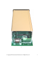
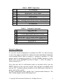
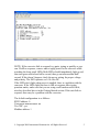
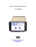
SM1 Protocol Converter
User Manual
ISI
Instrumental Solutions, Inc.
WWW.ISIDEV.NET
Introduction
The SM1 protocol converter can take readings from an SDI-12 instrument
and make the data available on a ModBus network.
On the SDI-12 side, concurrent & non-concurrent measurements are
supported, as well as measurements using CRC error detection. The SM1
can be configured to use any SDI-12 address from 0 – 9.
On the ModBus side, the SM1 address is configurable from 1 – 247.
ModBus ASCII protocol is supported at 9600 baud, 8 data bits, no parity.
The electrical interface is standard RS-485. For more information on the
ModBus interface, see the ModBus Registers section.
The unit is configurable via a text-based user interface using most any
terminal software.
Getting Started
All wiring connections are made inside the weatherproof enclosure, with the
wires passing through the waterproof fitting on the rear panel of the
enclosure.
Remove the rear panel by removing the 4 retaining screws and slide the
circuit board out to gain access to the connectors (see Figure 1).
The DB9P connector is used for configuring the SM1. A null-modem serial
cable with a female DB9 on each end is used to connect the unit to a PC
serial port. The cable only needs to have pins 2, 3 & 5 wired, with pins 2 & 3
swapped from end to end. Any serial terminal program (such as Hyperterm)
can be used. See Table 1 for more information on the DB9P connections.
The SDI-12 instrument connects to the screw-terminal block, using
terminals 1-3 labeled “SDI12”, “GND”, and “12V”, respectively. See Table
2 for more information on the terminal block connections. Note that terminal
3, which is used to supply 12 volts to the SM1, can also be used to power the
SDI-12 instrument.
The converter has 2 bi-color LED indicators on the front panel for indicating
SDI12 and Modbus data activity. The indicators light up green when the
converter is receiving data on the associated interface, and red when the
converter is sending data on the interface. These can be used to help
diagnose communication problems.
© Copyright 2009 Instrumental Solutions Inc. All Rights Reserved.
2
Figure 1
© Copyright 2009 Instrumental Solutions Inc. All Rights Reserved.
3
Pin 1
Pin 2
Pin 3
Pin 4
Pin 5
Pin 6
Pin 7
Pin 8
Pin 9
#1
#2
#3
#4
#5
#6
#7
#8
Table 1 - DB9P Connections
No connection
Receive data – RS232 input
Transmit data – RS232 output
DTR – internally tied to pin 6 for flow control loopback
Signal ground
DSR – internally tied to pin 4 for flow control loopback
RTS – internally tied to pin 8 for flow control loopback
CTS – internally tied to pin 7 for flow control loopback
No connection
Table 2 – Terminal Connections
SDI12 data line
SDI12 ground
+12VDC input to SM1 and SDI-12 device
Ground
Transmit data – RS232 output (same as DB9P pin 3)
Receive data – RS232 input (same as DB9P pin 2)
RS485 line A
RS485 line B
Default Configuration
To view the current configuration or configure the SM1, it is first necessary
to move the jumper on header J6 (which is located immediately behind the
screw-terminal block) from its normal 2-3 position to position 1-2. This
jumper must be returned to position 2-3 for the ModBus interface to work.
Please refer to the highlighted portion in Figure 1, where the jumper is
shown in position 2-3.
Next, plug one end of a null-modem cable (as described above) into the
DB9P connector on the converter, and the other end into an available serial
port on a PC. Terminal software should be set for 9600 baud, 8 data bits, no
parity, and no flow control.
To enter configuration mode, quickly type 3 question-mark characters. The
SM1 should respond with the following screen:
© Copyright 2009 Instrumental Solutions Inc. All Rights Reserved.
4
NOTE: If the converter fails to respond, try again, typing as quickly as you
can. If still no response, remove and re-apply power to the converter while
watching the front panel LEDs. Both LEDs should immediately light up red,
then turn green after about half a second, then go out after another halfsecond. If this doesn’t happen, check the power wiring for proper voltage
and polarity. The SM1 operates on 9-14 volts DC.
If the LEDs don’t light when power is applied, there is a problem with the
converter. If the LEDs light but there is still no response after typing
question marks, make sure that you are using a null-modem serial cable,
wired as described above in the Getting Started section. If the unit fails to
respond, there may be a problem with the converter.
The default configuration is as follows:
SDI12 address: 0
Concurrent measurement: no
Use CRC: yes
Modbus address: 1
© Copyright 2009 Instrumental Solutions Inc. All Rights Reserved.
5
To change a configuration setting, type the number of the setting followed
by the Enter key. The configuration mode has an inactivity timeout of 1
minute. If at any point during configuration the user goes 1 minute without
typing anything, the converter automatically returns to normal online
operation. Setting changes are saved as they are entered, so any changes
completed during the configuration session will not be lost if a inactivity
timeout occurs.
The following section describes each setting in detail.
1. SDI12 address
This is the address that the SM1 will use when communicating with the
SDI-12 instrument. The default value is 0. This value must match the
address of the SDI-12 instrument.
2. Concurrent measurement
This setting determines the type of SDI-12 measurement request that is
issued to the SDI-12 instrument. If concurrent measurement is turned off,
the SM1 will issue the SDI-12 Start Measurement command, “M”. If
turned on, the Start Concurrent Measurement command, “C”, will be
used. The data acquisition cycle is usually faster when using the Start
Measurement (non-concurrent) command. The default is to use nonconcurrent measurements.
3. Use CRC
This setting determines whether or not the SM1 requests a CRC (cyclic
redundancy check) when issuing a measurement request. CRC is used to
detect errors caused by line interference in the data received by the SM1.
If an error is detected, the SM1 will re-request the data. The default is to
use CRC.
4. Modbus address
This is the address that the SM1 will respond to on the ModBus interface.
The default value is 1. This value must match the address that the
ModBus master uses when communicating with the SM1.
5. Restore default settings
This selection resets all configuration parameters to the factory-default
settings.
© Copyright 2009 Instrumental Solutions Inc. All Rights Reserved.
6
6. Resume normal operation
This selection exits configuration mode and returns the converter to
online operation. Configuration mode has an inactivity timeout of 1
minute; if at any time after entering configuration mode no characters are
typed for 1 minute, the converter will automatically return to normal
online operation.
ModBus Registers
Each data field from the SDI-12 instrument is available in an individual
data-holding register on the SM1. The maximum number of data fields
supported is 20, and the data-holding registers are numbered 1- 20. Data
fields received from the SDI-12 device are placed in the data-holding
registers starting with register 1, in the order they are received from the SDI12 device.
Each numbered data-holding register in the SM1 (1,2,3, etc.) is 10 registers
wide internally, allowing for the storage of 20 characters of data (a ModBus
register is 2 characters, or bytes in size). As a result, the ModBus master
should use a register count of 10 when reading a data-holding register on the
SM1, which will result in 10 registers of data being returned by the SM1.
Each of the 10 registers returned contains 1 Unicode character. On the SM1,
a Unicode character has an ASCII character code in the least significant byte
(LSB) and a zero in the most significant byte (MSB).
For example, let’s say the first field returned by the SDI-12 instrument is the
value 123.45. When the ModBus master issues a Read Holding Register
command to read register number 1, the data portion of the ModBus
response from the SM1 will be the following 20 bytes (in hexadecimal):
0031 0032 0033 002e 0034 0035 0000 0000 0000 0000
The data is shown in 16-bit groups to reflect each of the 10 Unicode
characters returned by the SM1. The least significant byte of each Unicode
character contains the ASCII code for the data value:
31 – ‘1’
© Copyright 2009 Instrumental Solutions Inc. All Rights Reserved.
7
32 – ‘2’
33 – ‘3’
2e – ‘.’
34 – ‘4’
35 – ‘5’
00 – NULL terminator
00 – NULL pad character
00 – NULL pad character
00 – NULL pad character
ModBus Function Codes
The ModBus master uses Function Codes to tell the ModBus slaves what
type of operation to perform (Read Holding Register, Write Holding
Register, etc.). These are simple 1-character values that identify each
ModBus command. The SM1 supports the following Function Codes (the
character value of the function code is also shown):
Read Holding Registers (0x03)
Write Holding Register (0x06)
To read a data-holding register on the SM1, the ModBus master must use the
Read Holding Registers function code.
The SM1 uses the Write Holding Register function code to initiate a
measurement on the SDI-12 instrument. The following section describes
how this works.
Initiating a Measurement
The data-holding registers on the SM1 will contain zeroes until it takes a
measurement on the SDI-12 device. After that, they will contain the data
from the last SDI-12 measurement taken. The data-holding registers can be
read at any time, and reading them does not have any affect on their value.
A complete data acquisition cycle involves first telling the SM1 to take a
reading from the SDI-12 device, waiting for the reading to complete, then
reading the data-holding register(s) to get the results.
© Copyright 2009 Instrumental Solutions Inc. All Rights Reserved.
8
The SM1 has a status register at register address 1000 that is used to initiate
measurements and indicate when a measurement has completed. This
register is just like the data-holding registers except that it can be written to,
in addition to being read. This register normally contains zero. To initiate a
measurement, the ModBus master must use the Write Holding Register
function code to write a value of 1 to the register. This starts the
measurement process on the SDI-12 side.
The ModBus master should then read the status register (using the Read
Holding Registers function code) repeatedly until the returned value is zero,
which indicates that the measurement is complete. A polling rate of once a
second is sufficient when reading the status register.
As soon as the status register goes to zero, the ModBus master may then
read 1 or more data-holding registers (registers 1 – 20) to retrieve the SDI-12
data.
© Copyright 2009 Instrumental Solutions Inc. All Rights Reserved.
9
Specifications
SDI-12 interface:
Modbus interface:
Text interface:
Operating system:
Indicators:
Connections:
Temperature range:
Power requirements:
Enclosure:
External dimensions:
Weight:
SDI-12 v1.3 compliant
Modbus ASCII, 9600 baud, 8-bit, no parity
9600 baud, 8-bit, no parity, no handshake
Instrumental Solutions ISOS-11
2 bicolor LEDs for transmit/receive indication
Internal screw terminals, DB9 male (DTE)
-40°C to +85°C
12VDC 35ma idle, 35 ma avg, 55ma max
Extruded aluminum, IP65 rated
7.52” (19.1cm) L, 3.48” (8.84cm) W, 1.85” (4.7cm) H
15 ounces
© Copyright 2009 Instrumental Solutions Inc. All Rights Reserved.
10