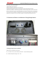
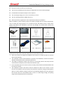
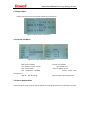
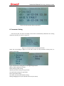
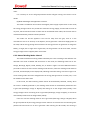
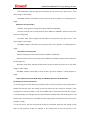
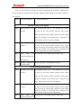
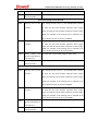
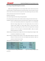
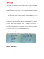
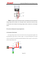
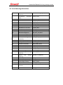
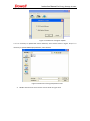
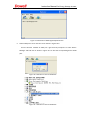
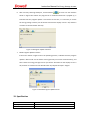
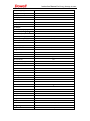
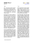
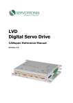
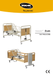
1
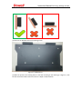
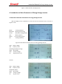
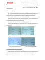
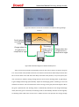
Instruction Manual for Energy Storage Inverter Instruction Manual for iPower 3000 Energy Storage Inverter V1.1 Dowell Electronic Technology Instruction Manual for Energy Storage Inverter Table of Contents 1. Device Introduction ....................................................................................................................... 4 2. Safety Precautions for Equipment ................................................................................................. 5 2.1 Safety Symbols ................................................................................................................. 5 2.2 Safety Precautions ............................................................................................................ 6 2.3 Battery installation and maintenance instruction ............................................................ 7 3. Connection and Power-on Initialization of Energy Storage Inverter ............................................. 8 3.1 Energy Storage inverter Installation .................................................................................... 8 3.2 Connection of Energy Storage Inverter ............................................................................. 11 3.3 Power-on Initialization ...................................................................................................... 13 4. Introduction to Menu Parameters of Energy Storage Inverter ................................................... 14 4.1 Real-time Parameter Information of Energy Storage Inverter .......................................... 14 4.2 Title Menu Display ............................................................................................................ 15 4.3 Indicating Lamp and Key Information ............................................................................... 15 4.3.1 Information of Indicating Lamps ............................................................................ 16 4.3.2 Key Information ...................................................................................................... 16 5. Query Operation ......................................................................................................................... 16 5.1 Report Menu ..................................................................................................................... 17 5.2 Inverter Info Menu ............................................................................................................ 17 5.3 History Report Menu......................................................................................................... 17 6. Parameter Setting ....................................................................................................................... 18 6.1 Battery Menu Setting ........................................................................................................ 19 6.2 Mode Menu Setting .......................................................................................................... 20 6.2.1 Automatic Working Mode--Auto ............................................................................ 20 6.2.2 Manual Working Mode--Manual............................................................................ 22 6.2.3 Passive Time-of-use Power Price--Too price P ....................................................... 23 6.2.4 Active Time-of-use Power Price--Tou price A ......................................................... 29 6.3. Setting of Off-grid Working State Parameters .................................................................. 37 6.4. Setting of In-grid Working State Parameters .................................................................... 38 6.5 System Time Setting .......................................................................................................... 39 6.6 Device Address Setting ...................................................................................................... 39 7. Start/Stop Operation ................................................................................................................... 40 7.1. Manual Start/Stop ............................................................................................................ 40 7.2. Remote Start/Stop ........................................................................................................... 41 7.3. Electric Power Turn-off of Energy Storage Inverter .......................................................... 41 7.4. Emergency Bypass Energy Storage Inverter ..................................................................... 41 8. Provision of Photovoltaic System Application ............................................................................. 42 8.1 Common AC Bus System ................................................................................................... 42 8.2 Common DC Bus System ................................................................................................... 44 9. Load Peak Clipping Treatment ..................................................................................................... 45 10. List of Warning Information ...................................................................................................... 46 11. Program Update ........................................................................................................................ 47 Instruction Manual for Energy Storage Inverter 12. Specification .............................................................................................................................. 50 13. General Fault Handling of Energy Storage Inverter ................................................................... 52 Instruction Manual for Energy Storage Inverter 1. Device Introduction Figure 1.1 Outside View of Energy Storage Inverter Figure 1.2 Lateral View of Energy Storage Inverter This product is mainly for the application of the schedulable photovoltaic power generation system which uses the most common lead-acid battery or lithium battery in an auxiliary way to form a small-size energy storage system, for optimized efficiency of battery energy. The energy storage type bidirectional inverter has the functions of off-grid and grid-connected power generation as well as electric energy bidirectional flow control, is equipped with the working modes such as automatic mode, manual switching mode and time-of-use power pricing mode, and has the functions of automatic switching and battery charging and discharging state management under the off-grid and grid-connected working modes. This inverter also has the Instruction Manual for Energy Storage Inverter function of intelligent grid-connected discharge, capable of adjusting its discharging power according to the change of the load power, to avoid feeding the excess energy into the grid and to maximize the user benefits. This energy storage inverter can be charged on the DC side or the AC side, can also be applied and work in the common AC bus system or the common DC bus system in combination with the photovoltaic system, or can also be used as a pure off-grid inverter. The device has an LCD display and keys, has a good human-machine interaction interface and stable performance, and has safe and reliable performance. The monitoring software features fault history recording, convenience to check later in the very rare case of a fault. 2. Safety Precautions for Equipment Before the use of inverter, please read all instructions and warning signs as well as this manual. The energy storage inverter strictly conforms to the safety requirements on design and test. The relevant safety codes shall be followed during the installation, operation and maintenance. Improper operation may result in electric shock hazard or damage to equipment and property. 2.1 Safety Symbols Instruction Manual for Energy Storage Inverter Explanation reference: While in using, the energy storage inverter must be operated according to the methods provided in the instructions. 2.2 Safety Precautions Electrical installation and maintenance shall be conducted by qualified electrician and shall comply with national wiring rules. The installation and maintenance of inverter must be performed by the qualified personnel in pursuance of the local electric appliance standards, the wiring rules and the requirements of the local electric power department or company. The necessary space shall be kept between the battery box and the energy storage inverter, and the safety protection of battery box shall be made well. Do not collide the inverter body. Gasoline, kerosene, slab, cotton yarn, rag and other inflammable and explosive goods are prohibited to be stored around the energy storage inverter. Avoid electric shock. The battery input and AC output of the inverter must be terminated to be executed for at least 5 minutes before installation or maintenance. The temperature of some parts for the inverter may exceed 60℃. To avoid being burnt, the inverter shall be cooled and then touched during the maintenance period. Ensure that children keep away from the inverter. Do not open the outer cover of the inverter voluntarily except when the wiring operation is performed. Touch or arbitrary change of components may result in Instruction Manual for Energy Storage Inverter personal injury or serious damage to the inverter. Static may damage the electronic elements. The proper method must be taken to prevent such damage; otherwise, the inverter may be damaged, which may void the warranty. If the equipment is not used according to the operation method specified by the manufacturer to cause the protective device to be damaged, it will void the warranty. For full isolation of inverter, the DC switch shall be turned off, the battery terminal shall be disconnected, and the AC terminal shall be disconnected. Before maintenance, fully isolate the energy storage inverter. Do not enter into the maintenance of inverters in other fields. Forbid to disconnect the battery terminal and the AC terminal during the normal running period of the energy storage inverter. 2.3 Battery installation and maintenance instruction The batteries are charged the factory, in the transportation and installation process of short circuit. The battery placed in the space should be well ventilated, not the battery is arranged in the sealing device, or may cause the equipment breakdown. Don't put the battery in high temperature, sunlight stove or in front of the fire, otherwise it may will cause battery leakage fire or rupture. The connecting cable should be as short as possible, to avoid excessive pressure drop. Before installing terminal connector and conducting battery system, check the battery system total voltage, positive and negative, to ensure that the installed correctly. If batteries need to be stored, disconnect the battery and charging equipment and load of the connecting portion and keep a cool environment, drying, ventilation. NOTE: The exact wording below does not have to be used as long as the intended information is provided. Servicing of batteries should be performed or supervised by personnel knowledgeable about batteries and the required precautions. When replacing batteries, replace with the same type and number of batteries or battery packs. CAUTION: Do not dispose of batteries in a fire. The batteries may explode. CAUTION: Do not open or damage batteries. Released electrolyte is harmful to the skin and eyes. It may be toxic. CAUTION: A battery can present a risk of electrical shock and high short-circuit current. The following precautions should be observed when working on batteries: a) Remove watches, rings, or other metal objects. Instruction Manual for Energy Storage Inverter b) Use tools with insulated handles. c) Wear rubber gloves and boots. d) Do not lay tools or metal parts on top of batteries. e) Disconnect charging source prior to connecting or disconnecting battery terminals. f) Determine if battery is inadvertently grounded. If inadvertently grounded, remove source from ground. Contact with any part of a grounded battery can result in electrical shock. The likelihood of such shock can be reduced if such grounds are removed during installation and maintenance (applicable to equipment and remote battery supplies not having a grounded supply circuit). 3. Connection and Power-on Initialization of Energy Storage Inverter Figure 3.1 Rear View of Energy Storage Inverter 3.1 Energy Storage inverter Installation Requirements of Installation Environment For indoor use only. Clean and tidy environment,easy accessibility,Dry place. Ambient temperature range: -20°C~45°C Instruction Manual for Energy Storage Inverter Relevant humidity: 0~95% (non-condensing). The inverter installation place should have independent air inlet and outlet passages. No flammable and explosive objects can be exposed. The overvoltage category for inverter connected to is III or II. The max. working altitude is 2000m above sea. Please consult our engineers for more requirements about the installation. Before installation, please carefully inspect the product package and the internal components, such as casing, DC wiring terminal, etc. To obtain the best and fastest services, please retain photos and contact your distributor if you find any damage. You should have received the following articles: Inverter×1 Wall-mounted×1 485terminal×2 User Manual×1 Warranty card×1 The selection of suitable installation location can not only ensure the optimum operating performance of the inverter, but also prolong the service life of the inverter. Select a site which can support the weight of the inverter for a long time (such as concrete wall or steel material). The installation location shall facilitate the operation and installation, electrical connection and later maintenance of the construction personnel. The height of installation location shall ensure to conveniently observe LED lamp and LCD screen (ensure the display screen to keep level with the eyes). Do air circulation well. The inverter must be vertically wall-mounted and located below with the inverter terminal. The installation location shall ensure that the ambient air flows to the inverter. If more inverters are installed in the same space, they shall have respective enough heat dissipation space to ensure sufficient cooling of inverters. The following diagrams show the spacing of the inverters with the recommended value. If there is a space large enough, the spacing range can be extended for future maintenance. Instruction Manual for Energy Storage Inverter (1) Take out the Backboard from the Packing Carton Figure 3.1 (a)Backboard (2) Mark the position of mounting holes on the wall according to the drawing (2.1 Figure b ). Use the drill with a bit of 8mm to drill six holes to a depth of 35mm-40mm Instruction Manual for Energy Storage Inverter Figure3.1 b Drawing (3) Find six M8 expansion bolts from the packing carton. Install them into the drilled holes, then use an electric screwdriver to tighten the screws to fix the backboard. (4) Mount the inverter gently to the backboard. Fix it with screws to make sure the inverter securely installed. 3.2 Connection of Energy Storage Inverter (1) DC battery cable connection Remove the DC wiring outer cover,As shown in Figure 2.1 Rear View of Energy Storage Inverter, Instruction Manual for Energy Storage Inverter find the silk screening BATTERY, connect the battery anode at “+” through the cable, and connect the battery cathode at “-” through the cable (anode is on the left, and cathode is on the right). It is recommended to use two 50mm2 power cables. Crimp SC50-6 terminal. Notes: the battery input terminal must be added with the DC circuit breaker (the rated voltage of the circuit breaker for 3000Wenergy storage inverter is 80 to 200V, and its rated current is 100A; the rated voltage of the circuit breaker for 2000Wenergy storage inverter is 80 to 200V, and its rated current is 70A; the circuit breakers conform to IEC60947-2 and GB14048.2 standards); if the battery is the lead-acid battery, the battery input terminal shall be additionally equipped with the overcurrent protection device, such as quick-acting fuse (the rated voltage of the quick-acting fuse is 80 to 200V, the rated current of 3000Wenergy storage inverter is 100A, the rated current of 2000Wenergy storage inverter is 70A, and the fuse conforms to IEC60269-1 and GB13539 standards). The battery polarity cannot be connected inversely, and inverse connection will result in damage to device or injury to operating personnel. (2) Communication terminal connection In Figure 3.1, find RS-485, which is external RS-485 communication (which can be optionally configured into WIFI). It is recommended to use RVVP3 core shielded line as the communication line. The connecting terminal is WEIPU waterproof aviation back nut plug SP1312/p, the wiring sequence is 4A(+), 2B(-), 3GND. (3) AC side connection Figure 3.2 Definition of AC Connecting Terminal As shown in Figure 3.1, find the silk screening AC LOAD/GRID, and refer to Figure 3.2 Definition of AC Connecting Terminal. LOAD-N is the load null line, LOAD-L is the load live wire, Generator Day1 and Generator Day2 are the dry contact signals to control over the DC generator, Reser Dry1 and Reser Dry2 are the reserved dry contacts, AC-L is the mains live wire, and AC-N is Instruction Manual for Energy Storage Inverter the mains null line. The users can select connection modes in line with different usage occasions: The users not connecting the DC generator only need to select to connect four cables: LOAD-N, LOAD-L, AC-L and AC-N. The users who need to connect the DC generator need to connect six cables: LOAD-N, LOAD-L, Generator Day1, Generator Day2, AC-L and AC-N. The recommended grid side incoming line is RV6mm2 wire, the recommended load side outgoing line is RV6mm2 wire, the connecting terminal is Tube type pre insulated terminal E6012; Generator Day1、Generator Day2 dry contact signal wire is recommended to18AWG American standard wire connecting terminal: Tube pre-insulated terminal E1008. Find the silk screening according to Figure 3.1, and connect PE earth wire to this point. Ground wire diameter is 6mm2, terminal is OT6-6. Note: AC side must external micro circuit breaker (GB10963.1, IEC60898 standard), The rated voltage is 230V ,rated current is 50A. 3.3 Power-on Initialization Find CHARGE BUTTON according to Figure 3.1, press it, and switch on the circuit breaker at the battery input side. Then loosen CHARGE BUTTON, and switch on the master switch at the AC input side. After the display screen is lightened, enter into the initialization interface, as shown in Figure 3.5. Instruction Manual for Energy Storage Inverter Figure 3.5 Main Interface of Display Screen 4. Introduction to Menu Parameters of Energy Storage Inverter 4.1 Real-time Parameter Information of Energy Storage Inverter After the display screen is powered on, enter into the main interface screen, as shown in Figures 4.1-4.3. Mode: working condition Mode-SET: working mode setting E-total: total power saving quantity SOC: battery capacity Power: current working power Fac: working frequency Figure 4.1 Main Menu Parameter Screen 1 of Energy Storage Inverter Ubat: battery voltage Ibat: battery current Load:off-grid load percentage Ugrid: grid voltage Uinv: inverter voltage Iac: off-grid load current Figure 4.2 Off-grid Main Menu Parameter Screen 2 Ubat: battery voltage Ibat: battery current CosΦ:power factor Ugrid: grid voltage Uinv: inverter voltage Iac: in-grid current Instruction Manual for Energy Storage Inverter Figure 4.3 Grid Connected Main Menu Parameter Screen 2 4.2 Title Menu Display The title menu displays different titles according to the different working modes of the energy storage inverter, corresponding to four statuses: Stop, Waiting, Running and Fault. Stop: the latter information is the current date time, as shown in 4.4 Waiting: the latter information is the countdown time before the normal operation when the detected battery status is normal, as shown in 4.5 Running: the latter information is the current date time, as shown in 4.6 Fault: the latter information is the current failure state of the energy storage inverter, as shown in 4.7 Figure 4.4 Stop Status Information Figure 4.6 Running Status Information Figure4.5 Waiting Status Information Figure 4.7 Fault Status Information 4.3 Indicating Lamp and Key Information Besides the display screen, there are two indicating lamps (one green indicating lamp and one red indicating lamp) and four keys on the display board, as shown in Figure 3.8. Instruction Manual for Energy Storage Inverter 4.3.1 Information of Indicating Lamps No. Status of Inverter Green Lamp Red Lamp Flash Flash 1 Initialize 2 Stop Go out Go out 3 Waiting Go out Go out 4 Running Light Go out 5 Fault Go out Light Figure 4.8 Information Screen of Display Board 4.3.2 Key Information There are four keys on the display board, respectively ESC, OK, UP and Down. ESC: cancel or exit OK: confirm UP: page up or increase the number when setting the variables Down: page down or reduce the number when setting the variables 5. Query Operation Press the key OK, and then the display screen will be automatically switched to the setting and query interface, as shown in Figure 4.1. Report: query of two latest alarm information Setting: parameter setting Inverter Info: information of energy storage inverter History Report: query of history alarm information Figure 5.1 Setting and Query Menu Instruction Manual for Energy Storage Inverter 5.1 Report Menu Display two latest alarm information and warning information. Figure 5.2 Report Menu Information 5.2 Inverter Info Menu Figure5.2 Inverter Info Menu Information Addr: device address Ver: software version number SN1: serial number Law: certification standard temperature1 Wifi ID: Wifi ID setting IP: level of protection Type: power level LCD Ver: display version Temp1: power tube Temp2: power tube temperature2 5.3 History Report Menu Inquire the history fault records, and be capable of inquiring 50 latest alarms information at most. Instruction Manual for Energy Storage Inverter Figure 5.3 History Report Menu Information 6. Parameter Setting Press the key OK, and then the display screen will be automatically switched to the setting and query interface, as shown in Figure 5.1. Figure 5.1 Parameter Query and Setting Interface Select the item Settings in Figure 6.1, click OK to enter into the parameter setting menu, as shown in Figure 6.2. Figure 6.2 Parameter Setting Menu of Energy Storage Inverter Battery: battery parameter setting Mode: working mode setting ISLAND: parameter setting in off-grid mode Grid: parameter setting in in-grid mode Date: system date setting Com Addr: communication address setting Debug: debugging menu (not required to be set by the client) Instruction Manual for Energy Storage Inverter 6.1 Battery Menu Setting Figure 6.3 Battery Parameter Setting Select Battery in the interface shown in Figure 5.2, press OK to enter into the battery parameter setting menu, as shown in Figure 5.3. Bat. Type: battery type selection (Acid, Li-on, NI-MH, etc.) Udown: battery minimum voltage protection value (range: 42-60) Uup: battery maximum voltage protection value (range: 42-60) Capacity: battery capacity (please set according to the battery connection information, for example, if the battery capacity is 200Ah, set to 200) When setting the value, always press the key Up, and the value increases rapidly. Press the key Up each time, and the value increases 1. Always press the key Down, and the value reduces rapidly. Press the key Down each time, and the value reduces 1. After the value is set, press the key OK to confirm. After confirmation, the cursor will automatically skip to the next setting. If press the key OK to confirm after Udown is set to 42V, the cursor will automatically skip to the area of Uup parameter setting. The battery parameters can be modified remotely through communication (RS485 or WIFI), and the specific parameter addresses are as follows: Baddress the following specific parameters 40101: battery type setting (0Acid, 1 Li-on, 2 NI-MH) 40102:battery minimum voltage protection value (the parameter value shall be set by 10 times; if the actual value is required to be 42V, it is necessary to set to 420) 40103: battery maximum voltage protection value (the parameter value shall be set by 10 times; if the actual value is required to be 55V, it is necessary to set to 550) Instruction Manual for Energy Storage Inverter 40104: battery capacity (if the actual battery capacity is 200Ah, it is necessary to set to 200) Notes: the battery parameter setting can be modified when the energy storage inverter is shut down, and modification is invalid when the inverter is in operation. If the selected accumulator cell is lithium battery, the lithium battery is required to be provided with BMS or battery protection board. 6.2 Mode Menu Setting Notice: In island mode, the inverter output is floating. Mode menu is mainly used for setting different working modes of the energy storage inverter. There are mainly 4 working modes: AUTO, Manual, Too price P and Too price A. The selection of 4 modes or switching of different modes into the other mode is required to be performed in the down state. Modification is invalid when the energy storage inverter works in the normal state. The parameters can be set on the screen and can also be set through communication (RS485 or WIFI). The mode address is as follows: 41008: working mode setting of energy storage inverter (0: AUTO, 1: Manual, 2 Too price P, 3 Too price A) Figure 6.4 Working Mode Setting of Energy Storage Inverter 6.2.1 Automatic Working Mode--Auto (1) Purpose This mode is actually a UPS standby mode. When the energy storage inverter is connected to the mains, the load is preferentially supplied with power by the mains and charges the accumulator cell. When the mains fails, the energy storage inverter runs in the off-grid mode and adjusts the stored energy of the accumulator cell to supply power to the load. (2) Implementation method Instruction Manual for Energy Storage Inverter This mode adopts the mains priority principle. When the grid is electrified, the energy storage inverter is bypassed to the grid, and the grid directly supplies power to the load while taking power from the grid and charging the battery for three stages through the energy storage inverter. After the battery is on a full charge, the energy storage inverter automatically stops charging to enter into the standby mode. After the grid is powered off, the energy storage inverter is automatically switched to the off-grid working status (ISLAND) (before the energy storage inverter works off-grid, the off-grid parameters (see Section 5.3) are required to be set). When the load is light, the off-grid mode is directly started, the in-grid to off-grid steady-state output switching time is less than 20 ms; if the off-grid load is heavy in the switching process or the photovoltaic inverter is connected at the AC side and the power of the photovoltaic inverter is high, the energy storage inverter will countdown to slowly start the off-grid working mode. When in the off-grid mode and after the mains is recovered, the energy storage inverter firstly tracks the grid phase and outputs the sine wave phase in the off-grid mode to be consistent with the mains, and then the off-grid mode is switched to the in-grid mode. If the battery is not on a full charge, it shall be charged; if the battery is on a full charge, the energy storage inverter will be directly switched to the standby mode and bypassed to the mains to supply power to the load. (3) Off-grid and in-grid parameter setting See Section 5.4 for the in-grid parameter setting and run according to the in-grid charging power limit set in Section 5.4. In the energy storage inverter, the default constant charging current is 0.2 C. If the actual charging power is larger than the charging power set in Section 5.4, the charging power of the energy storage inverter will be consistent with the charging power set in Section 5.4; if the actual charging power is lower than the charging limit power set in Section 5.4, the energy storage inverter will charge by 3 stages according to the default charging power. For example, if the charging limit power set in Section 5.4 is 1000W, and the maximum charging power of the energy storage inverter calculated according to the default value is 2000W, the energy storage inverter will charge according to the maximum charging power of 1000W; if the charging limit power set in Section 5.4 is 2500W, the energy storage inverter will charge according to the maximum charging power of 2000W calculated according to the internal default Instruction Manual for Energy Storage Inverter value. It is necessary to set the off-grid parameters before off-grid running. See Section 5.3 for details. (4) Mode advantages and application occasions This mode is suitable for the occasions with higher power supply requirements. In this mode, the energy storage inverter can provide the continuous energy supply, and the load can work at any time; UPS conversion function is faster and can be finished within 20ms; this function can be realized automatically, without manual operation. This mode can also be applied in the area far away from the grid, such as in the mountainous area or on the ship. In the daytime, the AC generator is started to supply power to the load, and the energy storage inverter fetches the energy from the AC generator to charge the battery; at night, due to high noise of generator, the AC generator can be shut down, and the energy storage inverter supplies power to the load. 6.2.2 Manual Working Mode--Manual This mode has different working modes selected by the users according to the different user demands. This mode is flexible and convenient. In this mode, the following states can be set: Charge, Discharge, Bypass, Island, Standby, etc, as shown in Figure 5.5. Select Manual and then press OK to confirm to enter into the working mode selection, select the working mode and then press OK, and the display screen displays OK, indicating successful setting, as shown in Figure 5.6. If the working mode cannot be changed when the energy storage inverter normally runs, it can be modified in the down state. In this mode, the above working modes cannot be automatically switched, namely, when the mains is suddenly powered on, the working mode cannot be automatically switched to the in-grid state (Discharge, Charge or Bypass) after being set to the off-grid state (Island); if the energy storage inverter is working in the in-grid state (Discharge, Charge or Bypass), it will not be automatically switched to the off-grid state (Island). If the user sets the working mode to the in-grid state (Discharge, Charge or Bypass) when the grid is powered off, the energy storage inverter will warn to reminder the user that the grid is powered off and cannot run in the in-grid state. After warning for 30 seconds, the warning is Instruction Manual for Energy Storage Inverter automatically canceled. If the mains is still power off, the energy storage inverter will repeatedly warn and run the in-grid state only after the power supply of the grid is normal. If the user sets the working mode to the off-grid state (Island) when the grid is normal, the energy storage inverter will warn to reminder the user that the grid cannot work in the off-grid state in the normal condition. After warning for 30 seconds, the warning is automatically canceled. If the mains is still normal, the energy storage inverter will repeatedly warn and run the off-grid state till the grid fault or disconnection of AC BREAKER is detected. Figure6.5 Setting Menu of Manual Mode Figure 6.6 Selection of Working State in Manual Mode The selection of working state in the manual mode can not only be operated through the display screen along with the keys, but also be set through communication (RS485 or WIFI). The specific parameter address is as follows: 41003:setting of working state in the manual mode (0:Waite, 2: Discharge, 3: Charge, 4: Island, 5: Bypass) 6.2.3 Passive Time-of-use Power Price--Too price P This mode is used for the area with power price differences in different time periods but without the photovoltaic in-grid system. Different working modes are set according to the power consumption peak time. The working mode can be set to in-grid discharge in the higher power price time period of the power consumption peak time to use the power of the battery to supply power to the load, and it can be set to in-grid charge in the lower power price time period of the low power consumption valley period to take power from the grid to charge the battery. The tariff can be saved by freely selecting the power consumption time. Instruction Manual for Energy Storage Inverter Figure 6.7 Passive Time-out-of-use Power Price Menu of Energy Storage Inverter Wave valley Family power consumption curve Charge when the AC grid price is cheap late at night Wave crest Wave valley The energy storage inverter Charge when the AC grid price is discharges at cheap late at night peak time Figure 6.8 Schematic Diagram of Peak and Valley Price There are four time periods on the display screen for the users to select. As shown in Figures 5.9---5.12, the four time periods can be set to one wave crest and three wave valleys and can also be set to two wave crests and two wave valleys and other time periods; in any time period, the user can select to make the energy storage inverter work in three working states: in-grid charge, in-grid intelligent discharge (automatically adjust the discharging power according to the load condition and ensure not to feed back the electric energy to the grid) and mains bypass. When the grid is powered off, the working mode is automatically switched to the off-grid discharge mode; when the grid is recovered, the working mode is automatically switched to the originally set working mode. When the current time is within the four time periods, the energy storage Instruction Manual for Energy Storage Inverter inverter runs in the mode set in each time period. When the current time is not within the four time periods and the grid is electrified, the energy storage inverter runs in the Bypass state, and the mains supplies power to the load; when the grid is powered off, the energy storage inverter is automatically switched to the off-grid mode to supply power to the load. When the mains is recovered to the normal state, the energy storage inverter will be automatically switched to the Bypass state again. Operating method: enter into Setting interface, select Mode to enter into the mode selection menu, select TOU price P mode and enter into the TOU price P mode configuration interface. (1) Setting of starting time and terminal time Figure6.9 Display Screen of Time Period 1 Figure6.10 Display Screen of Time Period 2 Figure 6.11 Display Screen of Time Period 3 Figure 6.12 Display Screen of Time Period 4 (1) Parameter setting of different time periods Parameters of time period 1 1st start:starting time of time period 1 (from T0h0m to N23h59m) 1st end:terminal time of time period 1 (from T0h0m to N13h59m, which must be later than the starting time) 1st mode:working mode of time period 1 (Discharge, Charge, Bypass) 1st PRMT: reserved parameters of time period 1 Parameters of time period 2 Instruction Manual for Energy Storage Inverter 2nd start:starting time of time period 2 (from T0h0m to N23h59m) 2nd end:terminal time of time period 2 (from T0h0m to N13h59m, which must be later than the starting time) 2nd mode:working mode of time period 2 (Discharge, Charge, Bypass) 2nd PRMT: reserved parameters of time period 2 Parameters of time period 3 3rd start:starting time of time period 3 (from T0h0m to N23h59m) 3rd end:terminal time of time period 3 (from T0h0m to N13h59m, which must be later than the starting time) 3rd mode:working mode of time period 3 (Discharge, Charge, Bypass) 3rd PRMT: reserved parameters of time period 3 Parameters of time period 4 4th start:starting time of time period 4 (from T0h0m to N23h59m) 4th end:terminal time of time period 4 (from T0h0m to N13h59m, which must be later than the starting time) 4th mode: working mode of time period 4 (Discharge, Charge, Bypass) 4th PRMT: reserved parameters of time period 4 Notes: T0hom represents 00:00 Today, and N23h59 represents 23:59 Next Day. (2) Setting rule of each time period ① The starting time of each time period must be prior to the terminal time. If the starting time is behind the terminal time, the setting of this time period will be invalid, for example, if the starting time of the time period 1 is 1st start:T7h30m and the terminal time of the time period 1 is 1st end:T5h45m, the setting of this time period will be invalid (because the starting time is 7:30 today but the terminal time is 5:45 today and the starting time is behind the terminal time, the setting is invalid); ② The time set for the four time periods cannot be interleaved, otherwise the setting of high value of time period is invalid, for example, if the starting time of the time period 1 is 1st start:T7h30m, the terminal time of the time period 1 is 1st end:T10h45m, the starting time of the time period 2 is 2nd start:T9h05m, and the terminal time of the time period 2 is 2nd end:T11h00m, the setting of time period 2 will be invalid because the time period 1 and the time Instruction Manual for Energy Storage Inverter period 2 have interleaved common time. ③ The time period can be set to 48 hours to a maximum limit, for example, the starting time of the time period 1 can be set to 1st start:T22h30m,and the terminal time of the time period 1 can be set to 1st end:N5h45m (because the starting time is 22:30 today, the terminal time is 5:45 tomorrow, and the starting time is prior to the terminal time, the setting is valid); ④ The working modes of the four time periods can be set according to the user demands, and the working mode of the time period 1 can be the same as or different from that of the time period 2. For example, the user can set the starting time to 1st start:T10h30m and the terminal time to 1st end:T15h00m in the time period 1, set the mode to in-grid Discharge in the higher power price period of the power consumption peak time and use the stored energy of the battery to supply power to the load; the user can set the starting time of the time period 2 to 2nd start:T23h05m and the terminal time of the time period 2 to 2nd end:N4h00m, set the mode to Charge in the lower power price period of the low power consumption valley period to take power from the grid to charge the battery. ⑤ After being set, the time and the working mode are not required to be repeatedly set, and the energy storage inverter can automatically store the set variables. ⑥ The energy storage inverter will automatically run the working mode of this time period after the clock time reaches the starting time of each time period and will automatically stop running to be switched to Bypass (grid electrified) or Island (grid failing) after this time period is ended. For example, if the starting time of the time period 1 is set to 1st start:T10h30m, the terminal time of the time period 1 is set to 1st end:T15h00m, and the mode is set to in-grid Discharge, the energy storage inverter can automatically run in-grid Discharge when the current time point reaches 10:30, and stop in-grid Discharge when the current time point reaches 15:00, the mode is switched to Bypass when the grid is electrified, is switched to Island when the grid is cut off, and is automatically switched to the working mode of the second time period till the second time period reaches. (3)Setting methods of time and working mode parameters There are two methods for setting the time and working mode parameters: display screen and key operation setting and communication (RS485 or WIFI) setting. The parameter addresses are as follows: Instruction Manual for Energy Storage Inverter Address Parameter Setting Range Specification Parameter Setting of Time Period 1 41015 Starting time of time The setting format is 0x****, four hexadecimal numbers period 1 in total, the first two numbers represent hour (range: 0-47), and the last two numbers represent minute (range: 0-59), for example, if the starting time is required to be set to 8:30, this area can be set to 0x0830. 41016 Terminal time time period 1 of The setting format is 0x****, four hexadecimal numbers in total, the first two numbers represent hour (range: 0-47), and the last two numbers represent minute (range: 0-59), for example, if the starting time is required to be set to 10:30, this area can be set to 0x1030. 41019 Working of 2:Discharge 3: Charge 5: Bypass state time period 1 41020 Reserved parameters of time period 1 Parameter Setting of Time Period 2 41021 Starting time of time The setting format is 0x****, four hexadecimal numbers period 2 in total, the first two numbers represent hour (range: 0-47), and the last two numbers represent minute (range: 0-59), for example, if the starting time is required to be set to 23:30, this area can be set to 0x2330. 41022 Terminal time time period 2 of The setting format is 0x****, four hexadecimal numbers in total, the first two numbers represent hour (range: 0-47), and the last two numbers represent minute (range: 0-59), for example, if the starting time is required to be set to 25:30, this area can be set to 0x2530. 41025 Working of 2:Discharge 3: Charge 5: Bypass state time period 2 41026 Reserved parameters of time period 2 Parameter Setting of Time Period3 Instruction Manual for Energy Storage Inverter 41027 Starting time of time The setting format is 0x****, four hexadecimal numbers period 3 in total, the first two numbers represent hour (range: 0-47), and the last two numbers represent minute (range: 0-59), for example, if the starting time is required to be set to 8:30, this area can be set to 0x0830. 41028 Terminal time time period 3 of The setting format is 0x****, four hexadecimal numbers in total, the first two numbers represent hour (range: 0-47), and the last two numbers represent minute (range: 0-59), for example, if the starting time is required to be set to 10:30, this area can be set to 0x1030. 41041 Working of 2:Discharge 3: Charge 5: Bypass state time period 3 41042 Reserved parameters of time period 3 Parameter Setting of Time Period4 41045 Starting time of time The setting format is 0x****, four hexadecimal numbers period 3 in total, the first two numbers represent hour (range: 0-47), and the last two numbers represent minute (range: 0-59), for example, if the starting time is required to be set to 8:30, this area can be set to 0x0830. 41046 Terminal time time period 3 of The setting format is 0x****, four hexadecimal numbers in total, the first two numbers represent hour (range: 0-47), and the last two numbers represent minute (range: 0-59), for example, if the starting time is required to be set to 10:30, this area can be set to 0x1030. 41063 Working of 2:Discharge 3: Charge 5: Bypass state time period 3 41064 Reserved parameters of time period 3 6.2.4 Active Time-of-use Power Price--Tou price A This mode is used for the area with power price differences in different time periods and using the photovoltaic in-grid system. Different working modes are set according to the power Instruction Manual for Energy Storage Inverter consumption peak and valley time as well as the sunny daytime, the cloudy daytime and the night. In this mode, the user only needs to set the peak period, the valley period and the general period as well as the weather information, and the energy storage inverter can judge the different modes in different working conditions. Table 5.1 Working States of Energy Storage Inverter According to Peak, Valley and General Periods as well as Weather Information No. Power Price Peak, Valley and General Periods Whether as well as Daytime and Night Grid State State Energy Storage Inverter 1 Wave crest Optional Electrified In-grid discharge 2 Wave crest Optional Power-off Off-grid 3 Wave valley Optional Electrified In-grid charge 4 Wave valley Optional Power-off Off-grid 5 Even wave Sunny daytime Electrified Bypass 6 Even wave Sunny daytime/night Electrified In-grid charge 7 Even wave Optional Power-off Off-grid 8 Not set peak, valley and general periods Optional Dis electrified Off-grid 9 Not set peak, valley and general periods Optional Electrified Bypass of Instruction Manual for Energy Storage Inverter Figure6.13 Active Time-of-use Power Price Menu of Energy Storage Inverter Photovoltaic generating capacity Nighttime Grid charging Morning Daytime Energy storage inverter Bypass grid Family Load Power consumption curve Photovoltaic power generation curve Evening Nigtimeht Energy storage inverter discharge Grid charging Possible discharge range of energy storage inverter Figure 6.14 Working Conditions of Energy Storage Inverter along with Photovoltaic System There are four time periods on the display screen for the users to select. As shown in Figures 5.15-5.18, the four time periods can be set to one wave crest and three wave valleys and can also be set to two wave crests and two wave valleys and other time periods; in each time period, the user only needs to set the peak, valley and general periods as well as the corresponding weather conditions, and the energy storage inverter can judge the required working state. In any time period, the energy storage inverter can work in three states: in-grid charge, in-grid intelligent discharge (automatically adjust the discharging power according to the load condition and ensure not to feed back the electric energy to the grid) and mains bypass. When the grid is powered off, the working mode is automatically switched to the off-grid discharge mode; when the grid is recovered, the working mode is automatically switched to the originally set working mode. When the current time is within the four time periods, the energy storage inverter runs in the mode set in each time period. When the current time is not within the four time periods and the grid is electrified, the energy storage inverter runs in the Bypass state, and the mains supplies power to the load; when the grid is powered off, the energy storage inverter is automatically switched to the off-grid mode to supply power to the load. When the mains is recovered to the normal state, the energy storage inverter will be automatically switched to the Bypass state again. Operating method: enter into Setting interface, select Mode to enter into the mode selection menu, select TOU price a mode and enter into the TOU price a mode configuration Instruction Manual for Energy Storage Inverter interface. Figure 6.15 Time Period 1 Menu of Active Time-of-use Power Price Figure 6.16 Time 6.18 Time Period 2 Menu of Active Time-of-use Power Price Figure 6.17 Time Period 3 Menu of Active Time-of-use Power Price Figure Period 4 Menu of Active Time-of-use Power Price (1) Parameter definition of different time periods Parameters of time period1 1st start: starting time of time period1 (from T0h0m to N23h59m) 1st end:terminal time of time period1 (from T0h0m to N13h59m, which must be later than the starting time) 1st mode:peak, valley and general information of time period 1 (0: wave crest 1: even wave charge 2: wave valley) 1st PRMT: weather information of time period1 (0: sunny daytime 1: cloudy daytime 2: night) Parameters of time period 2 2nd start:starting time of time period 2 (from T0h0m to N23h59m) 2nd end:terminal time of time period 2 (from T0h0m to N13h59m, which must be later than the starting time) Instruction Manual for Energy Storage Inverter 2nd mode:peak, valley and general information of time period 2 (0: wave crest 1: even wave charge 2: wave valley) 2nd PRMT: weather information of time period 2 (0: sunny daytime 1: cloudy daytime 2: night) Parameters of time period 3 3rd start: starting time of time period 3 (from T0h0m to N23h59m) 3rd end: terminal time of time period 3 (from T0h0m to N13h59m, which must be later than the starting time) 3rd mode: peak, valley and general information of time period 3 (0: wave crest 1: even wave charge 2: wave valley) 3rd PRMT: weather information of time period 3 (0: sunny daytime 1: cloudy daytime 2: night) Parameters of time period 4 4th start:starting time of time period 4 (from T0h0m to N23h59m) 4th end:terminal time of time period 4 (from T0h0m to N13h59m, which must be later than the starting time) 4th mode: peak, valley and general information of time period 4 (0: wave crest 1: even wave charge 2: wave valley) 4th PRMT: weather information of time period 4 (0: sunny daytime 1: cloudy daytime 2: night) Notes: T0hom represents 00:00 Today, and N23h59 represents 23:59 Next Day. (2) Setting rule of each time period ① The starting time of each time period must be prior to the terminal time. If the starting time is behind the terminal time, the setting of this time period will be invalid, for example, if the starting time of the time period 1 is 1st start:T7h30m and the terminal time of the time period 1 is 1st end:T5h45m, the setting of this time period will be invalid (because the starting time is 7:30 today but the terminal time is 5:45 today and the starting time is behind the terminal time, the setting is invalid); ② The time set for the four time periods cannot be interleaved, otherwise the setting of high value of time period is invalid, for example, if the starting time of the time period 1 is 1st Instruction Manual for Energy Storage Inverter start:T7h30m, the terminal time of the time period 1 is 1st end:T10h45m, the starting time of the time period 2 is 2nd start:T9h05m, and the terminal time of the time period 2 is 2nd end:T11h00m, the setting of time period 2 will be invalid because the time period 1 and the time period 2 have interleaved common time. ③ The time period can be set to 48 hours to the maximum limit, for example, the starting time of the time period 1 can be set to 1st start:T22h30m,and the terminal time of the time period 1 can be set to 1st end:N5h45m (because the starting time is 22:30 today, the terminal time is 5:45 tomorrow, and the starting time is prior to the terminal time, the setting is valid); ④ The working modes of the four time periods can be set according to the user demands, and the working mode of the time period 1 can be the same as or different from that of the time period 2. For example, the user can set the starting time to 1st start:T10h30m and the terminal time to 1st end:T15h00m in the time period 1, set the mode to in-grid Discharge in the higher power price period of the power consumption peak time and use the stored energy of the battery to supply power to the load; the user can set the starting time of the time period 2 to 2nd start:T23h05m and the terminal time of the time period 2 to 2nd end:N4h00m, set the mode to Charge in the lower power price period of the low power consumption valley period to take power from the grid to charge the battery. ⑤ After being set, the time and the working mode are not required to be repeatedly set, and the energy storage inverter can automatically store the set variables. ⑥ The energy storage inverter will automatically run the working mode of this time period after the clock time reaches the starting time of each time period and will automatically stop running to be switched to Bypass (grid electrified) or Island (grid failing) after this time period is ended. For example, if the starting time of the time period 1 is set to 1st start:T10h30m, the terminal time of the time period 1 is set to 1st end:T15h00m, and the mode is set to in-grid Discharge, the energy storage inverter can automatically run in-grid Discharge when the current time point reaches 10:30, and stop in-grid Discharge when the current time point reaches 15:00, the mode is switched to Bypass when the grid is electrified, is switched to Island when the grid is cut off, and is automatically switched to the working mode of the second time period till the second time period reaches. (3)Setting methods of time and working mode parameters Instruction Manual for Energy Storage Inverter There are two methods for setting the time and working mode parameters: display screen and key operation setting and communication (RS485 or WIFI) setting. The parameter addresses are as follows: Addres Parameter Definition Range Specification s Parameter Setting of Time Period 1 41015 Starting time of time The setting format is 0x****, four hexadecimal numbers period 1 in total, the first two numbers represent hour (range: 0-47), and the last two numbers represent minute (range: 0-59), for example, if the starting time is required to be set to 8:30, this area can be set to 0x0830. 41016 Terminal time of time period 1 The setting format is 0x****, four hexadecimal numbers in total, the first two numbers represent hour (range: 0-47), and the last two numbers represent minute (range: 0-59), for example, if the starting time is required to be set to 10:30, this area can be set to 0x1030. 41017 Peak, 0: wave crest 1: even wave charge 2: wave valley valley and general information of time period 1 41018 Weather information of time period 1 0: sunny daytime 1: cloudy daytime 2:night Parameter Setting of Time Period2 41021 Starting time of time The setting format is 0x****, four hexadecimal numbers period 2 in total, the first two numbers represent hour (range: 0-47), and the last two numbers represent minute (range: 0-59), for example, if the starting time is required to be set to 23:30, this area can be set to 0x2330. 41022 Terminal time of time period 2 The setting format is 0x****, four hexadecimal numbers in total, the first two numbers represent hour (range: 0-47), and the last two numbers represent minute (range: 0-59), for example, if the starting time is required to be set to 25:30, this area can be set to 0x2530. 41023 Peak, valley and general information of 0: wave crest 1: even wave charge 2: wave valley Instruction Manual for Energy Storage Inverter time period 2 41024 Weather information of time period 2 0: sunny daytime 1: cloudy daytime 2: night Parameter Setting of Time Period3 41027 Starting time of time The setting format is 0x****, four hexadecimal numbers period 3 in total, the first two numbers represent hour (range: 0-47), and the last two numbers represent minute (range: 0-59), for example, if the starting time is required to be set to 8:30, this area can be set to 0x0830. 41028 Terminal time of time period 3 The setting format is 0x****, four hexadecimal numbers in total, the first two numbers represent hour (range: 0-47), and the last two numbers represent minute (range: 0-59), for example, if the starting time is required to be set to 10:30, this area can be set to 0x1030. 41043 Peak, valley and general information of time period 3 0: wave crest 1: even wave charge 2: wave valley 41044 Weather information of time period 3 0: sunny daytime 1: cloudy daytime 2: night Parameter Setting of Time Period4 41045 Starting time of time The setting format is 0x****, four hexadecimal numbers period 3 in total, the first two numbers represent hour (range: 0-47), and the last two numbers represent minute (range: 0-59), for example, if the starting time is required to be set to 8:30, this area can be set to 0x0830. 41046 Terminal time of time period 3 The setting format is 0x****, four hexadecimal numbers in total, the first two numbers represent hour (range: 0-47), and the last two numbers represent minute (range: 0-59), for example, if the starting time is required to be set to 10:30, this area can be set to 0x1030. 41047 Peak, valley and general information of time period 3 0: wave crest 1: even wave charge 2: wave valley 41048 Weather information of time period 3 0: sunny daytime 1: cloudy daytime 2: night Instruction Manual for Energy Storage Inverter 6.3. Setting of Off-grid Working State Parameters Before the energy storage inverter runs the off-grid mode, the user needs to firstly set the off-grid parameters. See Figures6.19-6.20 for the specific operation. Press the key OK on the main screen to enter into the screen shown in Figure 6.19, select Island through the key up or Down, and then press OK to enter into the screen in Figure 6.20. Definitions of parameters: Vout: output voltage value when setting the off-grid operation. Freq: setting of off-grid frequency. 50Hz or 60Hz selected according to the local load of the user. Ack Mode: selection of off-grid mode active. Select AUTO: when the grid fails, the energy storage inverter can be automatically switched to the off-grid mode to run. Select Manual: before the energy storage inverter runs the off-grid mode, the user needs to manually confirm whether the energy storage inverter is active; after the user confirms, the energy storage inverter can be active in the off-grid mode. The off-grid parameters can be set through the communication (RS485 or WIFI). The specific parameter addresses are as follows: 41004: setting of Voutoff-grid output voltage value (if the actual off-grid output voltage is 220V, the parameter of 41004 will be set to 2200) 41011: setting of Freqoff-grid output frequency (if the off-grid output frequency is 50Hz, the parameter of 41011 will be set to 50; if the off-grid output frequency is 60Hz, the parameter of 41011 will be set to 60) 41012: setting of Ack Mode (0:Manual, 1: Auto) Figure 6.19 Selection of Off-grid Mode Menu Parameters Figure 6.20 Setting of Off-grid Mode Instruction Manual for Energy Storage Inverter 6.4. Setting of In-grid Working State Parameters In-grid parameter setting mainly refers to that the in-grid discharging power limit and the in-grid charging power limit are required to be set when the energy storage inverter operates in the in-grid mode. The grid frequency is not required to be set when the energy storage inverter operates in the in-grid mode, and the grid frequency is the self-adaptive grid frequency, and the in-grid discharge and charging power limits are only required to be set, as shown in Figure 5.21-5.22. The parameter definitions are as follows: P--discharge: maximum in-grid discharging power limit P--charge: maximum in-grid charging power limit The in-grid parameters can also be set through the communication (RS485 or WIFI). The specific parameter address are as follows: 41005:P--discharge setting (if the actual power limit is 3000, 41005 will be set to 3000) 41006:P--charge setting (if the actual power limit is 3000, 41006 will be set to 3000) Figure 6.21 Selection of In-grid Mode Menu Parameters Figure 6.20 Setting of In-grid Mode (1) In-grid charging power output of energy storage inverter The energy storage inverter runs according to the set in-grid charging power limit. In the energy storage inverter, the default constant charging current is 0.2C. If the actual charging power is higher than the charging power set in P-charge, the energy storage inverter will run at the set charging power; if the actual charging power is lower than the charging power set in P-charge, the energy storage inverter will charge by 3 stages according to the default charging power. For example, if the charging limit power set in P-charge is 1000W, and the maximum Instruction Manual for Energy Storage Inverter charging power of the energy storage inverter calculated according to the default value is 2000W, the energy storage inverter will charge according to the maximum charging power of 1000W; if the charging limit power set in P-charge is 2500W, the energy storage inverter will charge according to the maximum charging power of 2000W calculated according to the internal default value. (2) In-grid discharge power output of energy storage inverter The energy storage inverter runs according to the set in-grid discharge power limit. When discharging in the in-grid mode, the energy storage inverter will automatically track the load power change and adjust the its power output to ensure that the output power meets the load consumption but not cause the energy storage inverter to feed back the energy to the grid. In the operating process, if the actual load power is higher than the discharge power set in P-discharge, the energy storage inverter will discharge according to the discharge power limit set in P-discharge, and the insufficient load power will be provided by the grid; if the actual load power is lower than the discharge power limit set in P-discharge, the energy storage inverter will output the same power to meet the load demand according to the load power. 6.5 System Time Setting Set the system date and time through the display screen, as shown in Figure 6.23-6.24. Figure 6.23 Selection of System Date Menu Time Figure 6.24 Setting of System Date and 6.6 Device Address Setting Set the device address through the display screen, as shown in Figure 6.25-6.26. Instruction Manual for Energy Storage Inverter Figure 6.25 Selection of Device Address Menu Menu Figure 6.26 Setting of Device Address 7. Start/Stop Operation Smart-backup 3000energy storage inverter supports key start/stop and remote start/stop by communication. If the start/stop operation is not performed after entering into the on-off screen, the display screen will be automatically switched to the main menu screen 1 minute later. 7.1. Manual Start/Stop Firstly switch the display main screen to the main menu screen through the key ESC as shown in Figure 7.1 (the contents in the screen which can display the working mode are not always the same as that in Figure 7.1), press the key UP and then press OK to enter into the start/stop screen, as shown in Figure 7.2. Select Start through Up or Down, and then press OK to start the energy storage inverter. After starting the energy storage inverter, enter into the countdown time of 30S. After countdown, the energy storage inverter starts normally working. If there is a warning in the countdown process, the energy storage inverter will stop countdown, and the warning will be ended. Restart countdown. Figure 7.1 Main Menu Screen Figure 7.2 Start Screen If the inverter is normally operating and is required to be stopped, firstly switch the display main screen to the main menu screen through the key ESC as as shown in Figure 6.1 (the Instruction Manual for Energy Storage Inverter contents in the screen which can display the working mode are not always the same as that in Figure 6.1), press the key UP and then press OK to enter into the start screen, as shown in Figure 6.3. Select Stop through Up or Down, and then press OK to stop the operation of the energy storage inverter. Figure 7.3 Main Menu Screen 7.2. Remote Start/Stop This energy storage inverter supports the standard Modbus communication protocol. The user only needs to set the parameter in the address of 40108 on the communication interface to realize the start/stop operation. Set the parameter in 40108 to 1, namely, start command; set the parameter in 40108 to 0, namely, stop command. 7.3. Electric Power Turn-off of Energy Storage Inverter If the energy storage inverter is required to stop working due to maintenance or other reasons, firstly perform soft stop to the energy storage inverter according to 6.1 or 6.2, cut off AC BREAKER when the display screen displays Stop, and then cut off DC BREAKER. 7.4. Emergency Bypass Energy Storage Inverter When the energy storage inverter fails and cannot normally run, the grid bypass can directly supply power to the load through the bypass air switch on the block terminal to ensure the normal power supply to the load. Instruction Manual for Energy Storage Inverter Grid Inverter Distribution Box Bypass switch AC-N AC-L Notes: the bypass switch of the block terminal is not allowed to be turned on when the energy storage inverter normally runs. If the bypass switch is required to be turned on, firstly cut off the AC and DC switches on the energy storage inverter, and then turn on the bypass switch. 8. Provision of Photovoltaic System Application 8.1 Common AC Bus System The energy storage inverter can form the common AC bus micro grid system together with the photovoltaic in-grid inverter, as shown in Figure 7.1. The grid incoming side of the in-grid inverter is required to be connected to LOAD-N and LOAD-Las shown in Figure 7.2 to form the AC parallel energy storage system. Wind Turbine Wind inverter Grid Photovoltaic panel Photovoltaic inverter Energy storage inverter Load Battery Figure 8.1 Instruction Manual for Energy Storage Inverter Figure 8.2 Figure 8.1 Provision of Photovoltaic Common AC Bus System of Energy Storage Inverter Figure 8.2 AC Input Terminal AC parallel mode refers to that the energy from the battery panel and the energy from the accumulator cell are converged at the AC side respectively through the photovoltaic inverter and the energy storage inverter. When the grid is electrified, the power generated by the in-grid inverter is firstly consumed by the load. If the battery is not on a full charge, the residual power will be charged to the battery through the energy storage inverter; if the battery is on a full charge, the residual power will be directly fed back to the grid. If the photovoltaically generated power is insufficient to be consumed by the load, and the insufficient power can be supplied by the battery or the grid according to the consumer’s selection. When the grid fails or is cut off, the battery will establish an analog grid through the energy storage inverter. The in-grid inverter is connected to the output grid of the energy storage inverter to identify this grid and feed power. The power generated by the in-grid inverter is firstly consumed by the load. If the battery is not on a full charge, the residual power will be charged to the battery through the energy storage inverter; if the battery is on a full charge, the in-grid inverter will runs at the limited power to avoid the battery overcharge by changing the output grid frequency of the energy storage inverter; if the power generated by the photovoltaic inverter is not enough to be consumed by the load, the energy storage inverter will provide the insufficient energy to jointly supply power to the load. The energy storage inverter balances the energy according to the power generation of the in-grid inverter, the load energy consumption and the energy storage of the accumulator cell. The control to the in-grid inverter is very simple without communication between devices. Advantages of this system: ·The utilization efficiency of photovoltaic power generation is very high in the daytime, and Instruction Manual for Energy Storage Inverter the photovoltaic inverter can work when the grid fails or is cut off; ·The renewable energy sources (such as photovoltaic energy, wind power, etc.) are allowed to keep away from the accumulator cell; ·It is allowed to use different types of photovoltaic inverters from different manufacturers, and the power level is suitable for 1-5kW. 8.2 Common DC Bus System DC parallel mode refers to that the photovoltaic energy is directly connected to the DC bus in Parallel through the solar charger and the accumulator cell and is converged on the DC bus. Energy storage inverter Grid Load PV panel Wind Turbine Solar controller Wind controller Battery When the grid is electrified in the daytime and the voltage of the accumulator cell is lower than certain limit 1, the output power of the energy storage inverter varies with the load power to take power from the battery to supply power to the load and ensure not to feed back the energy to the grid; when the voltage of the accumulator cell is higher than certain limit and lasts for a time of period, the output power of the energy storage inverter is higher than the load power to feed power to the grid and ensure that the battery is not overcharged. When the battery voltage is lower than the under voltage value 2 and lasts for a time of period, the output power of the energy storage inverter becomes one half of the load power, and the grid and the energy storage inverter jointly supply power to the load; when the battery voltage is close to the under voltage value and lasts for a time of period, the bypass grid of the energy storage inverter Instruction Manual for Energy Storage Inverter directly supplies power to the load. When the grid is electrified at night, the energy storage inverter supplies power to the load through the bypass grid set by the user or the energy storage inverter supplies power to the load. When the grid is dis electrified, the energy storage inverter runs in the off-grid mode to supply power to the load. 9. Load Peak Clipping Treatment When the energy storage inverter runs in the in-grid or off-grid mode, the overload will be generated for a short time (such as inductive load start). In the working state of in-grid discharge, when the voltage of the accumulator cell is lower than certain limit 1, the output power of the energy storage inverter varies with the load power to take power from the battery to supply power to the load and ensure not to feed back the energy to the grid; when the battery voltage is lower than the under voltage value 2 and lasts for a time of period, the output power of the energy storage inverter becomes one half of the load power, and the grid and the energy storage inverter jointly supply power to the load; when the battery voltage is close to the under voltage value and lasts for a time of period, the bypass grid of the energy storage inverter directly supplies power to the load. When running in the off-grid mode, the energy storage inverter supports the instantaneous overload. The overload capacity varies with the overload power and the overload time. The overload time is not over 400ms at 2-time rated power. For the long-time overload, the energy storage inverter will warn. When this energy storage inverter runs in the in-grid mode, the total power is not allowed to exceed 6kW. The energy storage inverter will warn if total power is over 6kW for a time of period. For example, in the in-grid charge mode, the energy storage inverter takes power from the grid to charge the battery, the charging power P1 is 2000W, the load power P2 is 5000W, and the total power is P=P1+P2>6000W. Instruction Manual for Energy Storage Inverter 10. List of Warning Information No. Name of (Chinese) Warning 1 Initialization Fault 2 GFCI Detection Error GFCI_DEVICE_FAULT 3 AC Sensor Error GRID_HCT_FAULT 4 Grid Fault NO_GRID_FAULT 5 Grid Exist WITH_GRID_FAULT 6 EEPROM Error EEPROM_FAULT 7 AD Reference Level Error AD_REF_FAULT 8 Relay Error RELAY_FAULT 9 Inconsistency Error CONSIST_FAULT 10 BUS Overvoltage Error BUS_Over_Vol_FAULT 11 Fault Undervoltage Error BUS_Low_Vol_FAULT 12 ISO Fault PV1_ISO_FAULT 13 Battery Overvoltage Hard Protection Battery_Over_Vol_FAULT 14 Frequency Anomaly FREQ_CHECK_FAULT 15 leakage Overcurrent GROUND_I_FAULT 16 AC Short-circuit Fault GRID_SHORT_FAULT 17 DCI Fault DCI_FAULT 18 Connection Display Error COM_DSP_FAULT 19 Load overcurrent OVER_LOAD_FAULT 20 Inverter Voltage Error INVERTER_V_FAULT 21 Battery Warning High Voltage BATTERY_V_HIFAULT 22 Battery Warning Low Voltage BATTERY_V_LOWFAULT 23 Over-temperature Warning TEMP_FAULT 24 Grid Frequency Anomaly GRID_F_FAULT 25 Grid Voltage Anomaly GRID_V_FAULT 26 Temperature Sensor Error TEMPE_SENSOR_FAULT 27 Island DC Anomaly ISLAND_DCI_FAULT 28 Grid Overload Error Parameter Component Name of Warning (English) INITIAL_FAULT GRID_I_FAULT Instruction Manual for Energy Storage Inverter 11. Program Update The energy storage inverter supports RS485 to update the programs of energy storage inverter and control CPU. Before updating the program, firstly ensure that the energy storage inverter is not in the running state, and then cut off AC BREAKER to ensure that the energy storage inverter is not connected with the grid. The programupdate steps are as follows: 1. Find the screen shown in Figure 10.1, and double click the mouse to open the page shown in Figure 10.2. Figure 11.1 Updater Icon Figure 11.2 Updater Screen 2. Click open under File to enter into the page shown in Figure 10.3. If it is necessary to update the program of control CPU, select DSP Control Software; if it is necessary to update ARM, select ARM Display Software, and then click OK to enter into the screen shown in Figure 10.4. Instruction Manual for Energy Storage Inverter Figure 11.3 Selection of Program Update 3. If it is necessary to update DSP Control Software, select ST.exe shown in Figure 10.4; if it is necessary to update ARM Display Software, select LCD.bin. Figure 11.4 Selection of ProgramUpdate Format 4. Double click ST.exe to enter into the screen shown in Figure 10.5. Instruction Manual for Energy Storage Inverter Figure 11.5 Selection of DSPProgramUpdate Screen 5. Select COM port to enter into the screen shown in Figure 10.6. Correct selection method of COM port: right click My Computer to select Device Manager and find Port as shown in Figure 10.7 to find the corresponding device COM port. Figure 11.6 Selection of Correct COM Port Figure 11.7 Selection of Correct COM Port Instruction Manual for Energy Storage Inverter 6. After correctly selecting COM port, click Pull-down to enter into the interface shown in Figure 10.8. When the progress bar is finished and Success is popped up, it indicates that the program update is successful. At this time, it is necessary to restart the energy storage inverter (cut off the DC switch till the display screen is off, and then re-switch on the DC breaker after 5S). Figure 11.8 Program Update Interface 7. Failed Program Update Interface If the screen shown in Figure 10.9 in the updating process, it indicates that the program update is failed. Find out the failure causes (generally no normal communication), and then restart the energy storage inverter (cut off the DC switch till the display screen is off, and then re-switch on the DC breaker after 5S). Repeat the steps 1-6 again. Figure 11.9 Failed Program Update Screen 12. Specification Specification iPower Storage inverter 3kW Battery Data Nominal DC Voltage 48 V Instruction Manual for Energy Storage Inverter Battery Voltage Range 41-60V Charging Current Range 5—50A Battery Capacity 200Ah Discharge Depth 50%DOD Max discharge current 75A Voltage Range Battery Type 42 - 60 V NiCd,Li-ion,AGM,Gel AC Output Nominal AC output(on-grid) 3000 W Nominal output power(off-grid) 3000 VA Overload capacity 110%:474s 125%: 300s; 200%: 0.4s Nominal Output Voltage(on-grid) 220V/230 V/240V Inverter output voltage (off-grid) 220V/230 V/240V Nominal Output Current 13 A Max. Output Current 15 A Output Voltage Range 180 V - 265 V Voltage Frequency 50 /60Hz±1% The grid current harmonics < 3.0 % Harmonic voltage inverter <2% Efficiency 94.20% Feed-in Phase Max. Input Current AC Input Frequency Range Switching time Output Wave Form Single phase 28A 45-55HZ/55-65Hz <20ms Sine Wave Protection Function Over Discharge Protection Yes Overload Protection Yes Overvoltage Protection Yes Short Circuit Proof Yes Over temperature Protection Yes General Data Ambient Temperature Altitude Noise Standby Loss Topological Structure - 25°C ⋯ +45°C < 2000 m < 30 dB 5W Isolated Transformer Cooling Method Fan IP Degree of Protection IP21 Display LCD Optional communication Methods Size(W*H*D) Weight RS485 /WIFI (option) 525*400*220mm 40kg Instruction Manual for Energy Storage Inverter 13. General Fault Handling of Energy Storage Inverter When the status lamp Fault of the energy storage inverter is red, it indicates that there is a fault. The user can wait for 5 minutes to see whether the device can be recovered to the normal state. If the device cannot be recovered to the normal state, please cut off the AC switch and the DC switch in sequence, and then switch on the AC switch and the DC switch again according to the steps in 2.3. If there is still a fault, 批 lease dial the customer service hotline to consult or ask the specified professional maintenance personnel of the company for maintenance. If the energy storage inverter has abnormal sound, smell, vibration or other faults in operation, it shall be immediately stopped for inspection, and the specific situation shall be fed back to the technical service personnel. The energy storage inverter must be installed and maintained by the professionals. If there is any problem, please dial the service hotline to consult the relevant professionals. Do not handle presumptuously. Contact information Tel: +86(0)519-83181617, extension: 802 or 805 Email:[email protected]