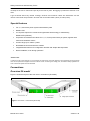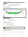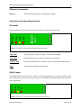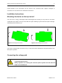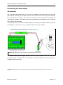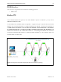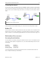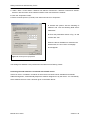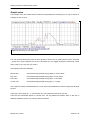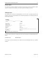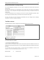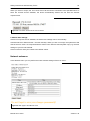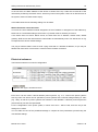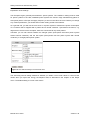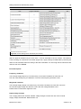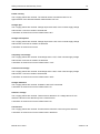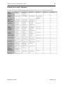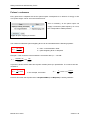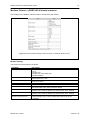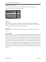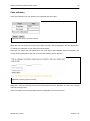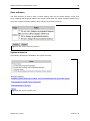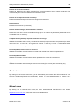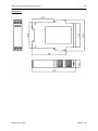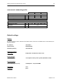
1
Manual econ sens + econ sens+ pro 3-phase Power Meter with Logging Function Version 1.40 Content Safety Instructions and Warranty Terms .................................................................. 1 Safety Instructions ............................................................................................................... 1 Intended use ........................................................................................................................................1 Hazard warnings .................................................................................................................................1 Information on disposal .......................................................................................................................1 Warranty Terms .................................................................................................................. 1 Description .................................................................................................................. 2 Special features .................................................................................................................. 3 Connections ................................................................................................................ 3 Overview S0 model ............................................................................................................. 3 Overview RS485 model ....................................................................................................... 4 Voltage path connections .................................................................................................... 4 Current path connections .................................................................................................... 4 Ethernet connection ............................................................................................................ 5 Indicators and operating controls......................................................................................... 5 S0 model ............................................................................................................................. 5 RS485 model .......................................................................................................................................5 Installation Instructions ............................................................................................. 6 Mounting the device on the top hat rail ................................................................................ 6 Connecting the voltage path ................................................................................................ 6 Installing the econ sens + in a 690V grid ............................................................................. 9 Installing the current sensors ............................................................................................... 9 Connecting the data outputs ................................................................................... 11 S0-Interface....................................................................................................................... 11 RS485-Interface ................................................................................................................ 12 Connecting the network ..................................................................................................... 13 Web Interface of the econ sens+ ............................................................................. 13 Accessing the web interface .............................................................................................. 13 Home menu....................................................................................................................... 15 Meter menu ....................................................................................................................... 16 Installation check routine „Installation check“....................................................................................18 Graph menu ...................................................................................................................... 20 Events menu ..................................................................................................................... 21 Content Settings menu ................................................................................................................... 21 General information on saving settings .............................................................................................22 Time/Date submenu ..........................................................................................................................22 Network submenu .............................................................................................................................23 Electrical submenu ............................................................................................................................24 Events (Proversion) submenu ...........................................................................................................29 Pulses / s submenu ...........................................................................................................................30 Modbus Pulses / s (S0/RS 485-Variante) submenu .........................................................................31 Pass submenu ...................................................................................................................................37 Save submenu ..................................................................................................................................38 System submenu...............................................................................................................................38 Contact menu .................................................................................................................... 39 Manual menu .................................................................................................................... 39 Initial Operation ........................................................................................................ 40 Troubleshooting ....................................................................................................... 41 Technical data........................................................................................................... 44 econ sens+ basic unit ........................................................................................................ 44 econ sens+ measuring coils: ............................................................................................. 46 Default settings ................................................................................................................. 46 Safety Instructions and Warranty Terms 1 Safety Instructions and Warranty Terms Safety Instructions Intended use The econ sens+ energy consumption meter is intended solely for the measurement of electrical parameters such as voltage, current, power, electrical energy, etc.. Installation and initial operation may only be performed by electrically qualified persons. Hazard warnings The warnings denote the following: Danger: Means that there is an immediate risk to the health of the user if the appropriate safety measures are not taken. Warning: Risk of potential damage to property or damage to the device if the appropriate safety measures are not taken. Information on disposal The econ sens+ energy consumption meter contains a small lithium battery. Never dispose of used batteries with normal household waste. They should be handed in at a collection point for used batteries. Warranty Terms econ solutions GmbH assumes no liability and furnishes no warranty for any consequences of improper use, in particular if the user and installation instructions have not been observed. The user must ensure that the device is not operated outside the specified technical parameters. In the event of changes or modifications to the device and of unauthorized repairs by the user, the warranty becomes void. Manual econ sens+ Version 1.40 Safety Instructions and Warranty Terms 2 All information contained in this manual was prepared to the best of our knowledge and checked with care. Nevertheless, errors cannot be completely ruled out. For this reason, the information contained in this manual is not associated with any obligation or guarantee of any kind. The authors, companies and the publisher assume therefore no legal responsibility and will not assume any consequential or other liability, that might arise in any way from the use of this information or parts of such, also not for any breach of patent rights or other rights of third parties that could result therefrom. This work is protected by copyright. All rights, including those concerning the translation, reprint and duplication of the manual or parts thereof, are reserved. No part of the work may be reproduced in any form (photocopy, microfilm or other method) without the written approval of the publisher, not even for teaching purposes, or be processed, duplicated or disseminated using electronic systems. Description econ sens + is a compact, versatile energy consumption meter with a web interface and memory function. It measures the voltage and the current of the individual phases and the voltage between PE and the neutral conductor. When calculating the power, econ sens+ is able to differentiate between the generated and consumed power. The energy consumption values calculated from the power data are displayed to the user via the web interface and made available for any energy monitoring systems or similar that may be connected via: 1. 2 x S0 pulse outputs to DIN EN 62053-31 (for consumed and generated active energy) 2. Modbus TCP 3. Modbus RTU (RS-485) Allowed the detection of active, reactive and apparent power, current and voltage, each per line and further readings on the Modbus interface (see Chapter Modbus). The econ sens+ samples the input voltages and currents at 32 samples/signal period. To do this, it tracks the frequency of the inputs and continuously updates its sampling rate accordingly. At the same time, the econ sens+ resamples the input voltages at 1kHz. These samples give a picture of the waveform. These waveforms are stored for several types of events. The econ sens + has a size of 16MB memory to store values, logs and events. It holds power logs per second for the last 2 days. It logs all measurements per minute for the last 39 days, per interval (10 or 15 Manual econ sens+ Version 1.40 Safety Instructions and Warranty Terms 3 minutes) for the last 13 months and per day for the last 10 years. No logging is performed if the time is not valid. Logs are stored after every interval. Average, minimum and maximum values are determined over the interval. The interval is expressed in seconds and can be either 600s (10min) or 900s (15min). Special features For 2, 3, and 4-wire power systems with arbitrary load Modbus TCP 2 x S0 pulse outputs for consumed and generated active energy or alternatively, Modbus RTU (RS 485) Acquisition of instantaneous values for U, I, P, Q and power factor per phase, together with mean and cumulative values Current range up to 3200 A / phase No additional current transformer needed Integrated web interface for configuration and fast and simple data acquisition Quick installation, even during operation* *Please note! In order to log the current strength, it is not necessary to switch off the consumer load that is to be measured, as the Rogowski coils can be opened and wrapped round the conductor. When connecting the voltage path, the relevant safety regulations for work on electrical systems must be observed! Connections Overview S0 model Figure 1 shows the layout of the econ sens+ connections (S0 model) Figure 1: econ sens + connections (S0 model) Manual econ sens+ Version 1.40 Safety Instructions and Warranty Terms 4 S0-pulse outputs Imp - : Pulse output (Open Collector, NPN) for generated energy Imp + : Pulse output (Open Collector, NPN) for consumed energy GND : Common ground for Imp – und Imp + Overview RS485 model Figure 2 shows the layout of the econ sens+ connections (RS485) RS-485 Modbus RTU- interface Figure 2: econ sens + connections (RS485) RS485 model (Modbus RTU): A: data line B Modbus RTU B: data line A Modbus RTU GND : Common ground for data line A and B. Voltage path connections L1, L2, L3: Terminals for phases L1, L2 and L3 PE: Terminals for the PE conductor Ext: “Extension” terminal. Is bridged with terminal L2 To avoid damage to the econ sens+, the maximum torque for tightening the terminals is < 2.5 Nm. Current path connections I1, I2, I3: Manual econ sens+ Connection socket (RJ11) of the econ sens+ coils for current measurement Version 1.40 Safety Instructions and Warranty Terms 5 Ethernet connection Ethernet: Ethernet connection (RJ45) / 100 Mbit (fixed speed) Indicators and operating controls S0 model Figure 3 shows the layout of the indicators and operating controls of the econ sens+. Figure 3: econ sens+ indicators and operating controls (S0 model) “Log” LED: Lights up as soon as the econ sens+ records measured data “Link” LED: Lights up when there is an active connection to the network “Activity” LED: Lights up or flashes as soon as data is sent or received via the Ethernet port Reset: Reset button to perform “Factory Reset”. RS485 model The RS485 model of the econ sens + differs in its external appearance only by the absence of the lower right corner of the front panel (see Figure 4). All operating and display elements are identical to those of S0 model. Figure 2: econ sens+ indicators and operating controls (RS485 model) Manual econ sens+ Version 1.40 Safety Instructions and Warranty Terms 6 Further details on the connections can be found in the “Technical Data” chapter; examples of connections can be found in the “Installation Instructions”. Installation Instructions Mounting the device on the top hat rail The econ sens + energy consumption meter was designed for mounting on a top hat rail. The device is attached at an angle to the top hat rail with the upper retaining lug and locked into place with light downward pressure (see Fig. 5). Figure 3: Mounting the econ sens+ Figure 4: Dismounting the econ sens+ The device is dismounted as shown in Fig. 6. Press the device downwards using light pressure and then pivot it upwards. Connecting the voltage path Installation of the econ sens + may only be performed by specially trained staff (e.g qualified electricians). Safety regulations for working with electrical power systems must be observed under all circumstances! Manual econ sens+ Version 1.40 Safety Instructions and Warranty Terms 7 The econ sens+ energy consumption meter can be used with various public power supplies: 3-phase four-wire power system (with neutral conductor) 3-phase three-wire power system (without neutral conductor) Single-phase power system Fig. 7 shows the integration of the econ sens + into a 3-phase 4-wire power system. Figure 7: econ sens+ connection diagram to a 3-phase 4-wire power system The phases L1, L2 and L3 of the voltage path must be protected by means of automatic circuit breakers to prevent the system from being damaged in the event of a short circuit. A B6 (max. B10) automatic circuit breaker is recommended. For safety reasons it is preferable to use a short-circuitproof conductor (NSGAFÖU) in front of the circuit breakers. Manual econ sens+ Version 1.40 Safety Instructions and Warranty Terms 8 If several econ sens+ devices are installed next to one another it is recommended that you use a clamping unit with series terminals. As a result it is easier to direct the fused voltage path in parallel to all devices. Table 1 shows the terminal assignment of the voltage path terminals for the various types of power system. Table 1: Connection diagrams of various power system topologies Manual econ sens+ Version 1.40 Safety Instructions and Warranty Terms 9 Installing the econ sens + in a 690V grid The econ sens + can also be used in a 690 V grid (IT-System). It should be noted that a neutral conductor is required. This is because the power supply of this device is itself designed for voltages on the primary side to 440Vrms. When connected to a 690 V power connection so the image has to be used according to Fig. 8. Abbildung 8: Anschlussschema 690 V-Netz Installing the current sensors To install the current sensors (Rogowski coils), wrap these around the conductor that is to be measured, as shown in Fig. 9. This can be a cable or also a conductor rail. Insert the free end of the cable into the end piece of the coil until it latches into place. The coil must form a closed loop around the conductor. Figure 9: Installation of the current sensors The label on the coil must be aligned in such a way that it points towards the consumer. This ensures the correct direction of current flow through the coil. Please also ensure that each sensor matches the corresponding phase of the voltage path (coil L1 to phase L1, etc.) Manual econ sens+ Version 1.40 Safety Instructions and Warranty Terms 10 Alignment of the coil with the current flow If possible, secure the coil round the conductor (cable, conductor rail, etc.) with a tie wrap. Make sure that the loss angle of the coil is not too large (see Fig. 10). In the case of loss angles > +/-5°, the relative error of measurement is also greater and consequently also the relative deviation of the measured current and the calculated parameters (e.g. power). Figure 10: Loss angle of the current sensors Manual econ sens+ Version 1.40 Safety Instructions and Warranty Terms 11 Connecting the data outputs S0-Interface The consumption data measured by the econ sens+ is outputted via the pulse outputs Imp+ and Imp(open-collector NPN outputs) as a pulse sequence. Each output pulse is 50 ms long and corresponds to a defined amount of energy in Wh. This can be configured via the web interface. (For details see “Web Interface” chapter). The default value for this pulse weighting is 10 Wh/pulse, which corresponds to an output of 100 pulses/kWh. The pulse outputs are used for the automated capture of the energy consumption values by means of a data logger, e.g. the Econ Unit. Fig. 11 shows the layout of the pulse interface. Abbildung 11: Belegung der S0-Ausgänge und mögliches Anschlussschema The distance between the data logger and the econ sens + may be amount to max. 50 meter. When connecting a cable, a shielded cable is recommended *, as Belden YE00820. For shorter distances an unshielded cable can be used. * A shielded cable should come in all applications where massive electromagnetic disturbances from the environment is expected. Manual econ sens+ Version 1.40 Safety Instructions and Warranty Terms 12 RS485-Interface The econ sens + supported on this interface the following protocols: Modbus RTU Modbus RTU Via the RS485 Modbus RTU protocol, the values "Modbus / pulses / s submenu " p.17 ff) can be retrieved according to section. To use Modbus RTU a Modbus master is required. In a segment of up to 32 devices can be connected together. For more than 32 devices in a segment repeaters are required. The wiring of components is a “linear structure”, as shown in Fig 13. Other bus topologies, such as Star shape is not possible. At the beginning and end of a segment, the cable is terminated with resistors (bus termination). Put between lines A and B a 120 Ω termination resistor. As a connecting line between the devices we recommend a shielded cable 2x2x0, 8, for example, Belden YE00820 or a Cat 5 network cable. The maximum length is 1200 meters. Figure 13: Assignment of the RS485 outputs (here with one econ sens+ as gateway) Manual econ sens+ Version 1.40 Safety Instructions and Warranty Terms 13 Connecting the network The econ sens+ energy consumption meter has a 100BASE-T network connection for web interface access. This can be connected to a PC either directly or via a node such as a hub or switch. Connect the econ sens+ to your hub/switch using a patch cable (1:1) or directly to your PC (using a crossover cable). Figure 14: econ sens+ network connection Further information on the IP address settings, etc. can be found in the “Initial operation” chapter. Modbus TCP Via the network connection measured values and events (Pro variant) can be accessed via the Modbus protocol for both versions (S0/RS485). The parameter settings are performed in the Modbus / pulses / s submenu. The corresponding register addresses can be found in the manual on page 34 ff. Web Interface of the econ sens+ Accessing the web interface The web interface is accessed by entering the IP address of the econ sens+ in the address bar of the web browser (Firefox, IExplorer, GoogleChrome, etc.). The network default settings of the econ sens+ are as follows: IP address: 192.168.0.1 Subnet mask: 255.255.255.0 Standard gateway: 192.168.0.254 For the web interface to be accessed, ensure that the user PC is in the same network as the econ sens+. Configure as follows (e.g. under WinXP): Manual econ sens+ Version 1.40 Safety Instructions and Warranty Terms 14 1. Under “Start / Control Panel / Network and Internet Connections / Network Connections” doubleclick the LAN connection of the network interface card connected to the network. 2. Click the “Properties” button. 3. Select “Internet protocol (TCP/IP)” from the list and click on “Properties”. 4. Activate the options “Use the following IP address” and “Use the following DNS server addresses”. 5. Enter the parameters shown in Fig. 10 and confirm with “OK”. When the above IP address is entered in the web browser, the econ-sens+ homepage should appear. Figure 15: Internet protocol properties The settings for Windows 7 are performed in the Network and Sharing Center. Accessing the web interface in a network with a DHCP server If the econ sens+ is located in a network in which there is a DHCP server available for automatic address assignment, it automatically adopts the address assigned to it by this server. You can identify which address the econ sens+ has been given in the DHCP Server. Manual econ sens+ Version 1.40 Safety Instructions and Warranty Terms 15 Home menu 1 2 3 4 Figure 12: "Home" menu screen On the home screen of the econ sens + you find the following information: 1. Menu bar to navigate the individual menus of the econ sens+ 2. Device name and current time/date 3. Language selection menu 4. Information bar Time/date settings Start-up time Operating system version Application software version Manual econ sens+ Version 1.40 Safety Instructions and Warranty Terms 16 Meter menu Econ sens+ displays the measured values in tabular form in the Meter menu. This table is shown in Fig. 17. * Figure 13: econ sens+ table of measured values The following are displayed: the voltages of the phases L1, L2, L3, the corresponding currents, as well as the active and the reactive power per phase and the “power factor” (for pure sinusoidal alternating currents, this is synonymous with the familiar cos phi). You can refresh the display by pressing the F5 key on your keyboard as required or you can activate the arrow button next to the word “Actual power”. Then the display will be updated every second. The vector diagram below the table serves to visualize the phase shift between the voltages L1, L2 L3 and the corresponding currents. *The “Un” specification below the table indicates the so-called neutral conductor voltage (voltage difference between the neutral conductor and the protective earth). This is needed for the Events menu, which deals with network analysis. This menu is however disabled in this software version. Manual econ sens+ Version 1.40 Safety Instructions and Warranty Terms 17 You can also have the voltage and the current on the three phases displayed as a curve by selecting the Curve option at the bottom left of the screen. (see Fig.18) Figure 18: Current and voltage curves Econ sens+ is able to measure and display both the generated and the consumed active power. This is illustrated in Fig.12. The consumed active power is shown in the table in blue, while the generated active power with a negative sign is shown in red. In the above example this means that on phase L1 power is only consumed and on phase L2 power is only generated. If power is both consumed and generated at the same time on one phase, econ sens+ shows the sum of the two. An example: With your photovoltaic power system with downstream inverter you generate 1 kW on each of the three phases L1, L2, L3, at the same time consuming 500 Watt on phase L2 for various household appliances. Then your table of measured values would look like the table in Fig. 19. Figure 19: Table of measured values for the example Manual econ sens+ Version 1.40 Safety Instructions and Warranty Terms 18 Installation check routine „Installation check“ The econ sens + has a small installation check routine, called "installation check". General, it is measurement assumed coils that were all installed correctly, and the measured load has a power factor of >0.71 (phase shift between U and I <45 °). Then the table of measurements in Figure 20 is shown. In this example, a load of about 6 kW measured at L1, L2 and L3 are unloaded. Figure 20: Table of measured values without error message Is an installation error, for example, the coil L2 is placed around the voltage circuit from L1, the power factor falls below 0,71 and it appears in the table of measurements the following error message: In the table of measured values it can be seen that the power factor of phase 2 has dropped below 0,71 and the phase shift between U2 and I2 in the graphic "Phasor" has 120°. This is a typical error pattern for the above- named Installation errors. Figure 21: Error message Manual econ sens+ Version 1.40 Safety Instructions and Warranty Terms 19 Note: Due to the simplicity of the installation check routine, there are also cases where there are no installation errors, the routine but still displays an error message such as: a) The measured power is exclusively produced and there is a little or no consumed power b) The power factor of the connected load is actually <0,71 Therefore, always be careful to correct installation of the measuring coils and their assignment to the voltage path to avoid misunderstandings. Manual econ sens+ Version 1.40 Safety Instructions and Warranty Terms 20 Graph menu In the Graph menu, the measurement results are represented as a measuring curve. Fig. 22 shows an example of such a curve. Figure 14: Measuring curve in Graph menu The sum of the power/energy from the three phases is shown over a certain period of time. Using the – period and + period buttons next to the X-axis label you can toggle through the measuring curves step by step (e.g. every day of a month). The following views are available: Month view: Consumed and generated energy (kWh) in 15-min steps Day view: Consumed and generated energy (W) in 15-min steps Hour view: Consumed and generated energy (W) in 1-min steps 15-min view: Consumed and generated energy (W) in 1-s steps The measured values associated with the curves can be downloaded as a text file using the Download function Using File-> Save page as… in your browser you can transfer the text file to your PC. There are two Download options to choose from; the only difference between them is the use of different separators (comma or point) in decimal numbers Manual econ sens+ Version 1.40 Safety Instructions and Warranty Terms 21 Events menu The Events menu is used to configure the recording of network events. These are needed for network analysis in accordance with EN 50160. This function is optional available (Pro-version). Settings menu The Settings menu is used for the parameterization of the econ sens+. All settings required for the operation of the device can be performed in the corresponding submenus. The main page of the menu shows status information. Figure 23: Main page of the Settings menu You can access the submenus by entering your user name and password. The default settings are as follows: User name: user Password: pass Via the login you will be redirected to the submenus and will automatically land in the Time/Date submenu. Manual econ sens+ Version 1.40 Safety Instructions and Warranty Terms 22 General information on saving settings The overall configuration procedure for the econ sens+ is spread over several menus and various input windows. On every menu page there is an Accept button. This is used to save your inputs on the respective menu page, i.e. if you change the menu page and forget to press Accept, your inputs will revert to the default values. In order to permanently save your settings at the end of the overall configuration procedure, select Store changes in permanent memory in the Save menu and confirm with Accept. On every menu page you will be reminded to permanently save your settings with the message “Remember to save your changes permanently”. Time/Date submenu Time/Date submenu is used to configure the time and date settings of the econ sens+. Figure 24: Time/Date submenu The following options are available: 1. Time setting using NTP time server If the econ sens+ is in a network in which a time server with NTP protocol is available, the device can adopt the time and date from this server. To do this, activate the Adopt time and date from time server select box. You can define up to four ntp time servers. To do this enter the IP addresses or names of the respective servers in the fields adjoining ntp time servers 1..4, e.g. ptbtime1.ptb.de Manual econ sens+ or 192.53.103.108 Version 1.40 Safety Instructions and Warranty Terms 23 When you click on Accept, the econ sens+ first of all checks the connection to the specified server. If there are several servers available, the device automatically selects the one with the shortest response time. Figure 25: Connection to time server was successful 2. Manual time settings: If there is no ntp time server available, the device time settings can be set manually. Activate select box Date and time = set time manually. When you click on Accept, the system time and date of the econ sens+ are compared with the values in the Set time manually field. Copy e.g. the time settings of your PC into this field. Click on Reset to reset your entries to the default values. Network submenu In the Network menu you can perform the basic network settings of the econ sens+. Figure 26: Main page of the Network menu Manual econ sens+ Version 1.40 Safety Instructions and Warranty Terms 24 In the info area, the MAC address of the device is shown at the top. Under this is listed all of the information provided by the DHCP server, which may exist in the system. If there is no DHCP server in the system, these info fields remain empty. In the table below this the following settings can be made: Which IP address should be used? You have the choice between manual assignment of the IP address or assignment of the address by DHCP server. The default setting is the function: If possible obtain IP address per DHCP. If the device does not find a DHCP server, the data from the IP address, subnet mask, default gateway, DNS server and network device name fields are automatically used. The data shown in Fig. 20 represents the device default settings. The ping IP address field is used to send a ping command to a defined IP address, as you may be familiar with from DOS. This function is used to test the network connection. Electrical submenu The Electrical submenu is used for configuration Figure 27: Main page of the Electrical menu Econ sens+ can be used in various different power systems, e.g. in 2, 3 and 4-wire power systems with any load. The device can be operated in power systems with a nominal voltage starting at 120V (e.g. USA), as well as in power systems with 230/400 V and 400/690 V. Different power frequencies (50 und 60 Hz) can also be represented. For the configuration of the power system, in which econ sens + will be used, there are only a few settings to be made. You can either use one of the predefined settings or compile all of the parameters yourself using the user-defined settings. Manual econ sens+ Version 1.40 Safety Instructions and Warranty Terms 25 Explanation of the settings: The European region generally has 230/400 V power systems. The 130/230 V setting must be used for power systems in the USA; 400/690V power systems are found in large manufacturing plants or wind power plants. In Europe the supply frequency is 50 Hz in the USA it is 60 Hz. Before you change any of these parameters, you should find out which setting needs to be selected. As a general rule, you will use the econ sens+ in a power system or measure the power consumption of a consumer that is supplied with 3 phases and a neutral conductor. Symmetrical consumers, e.g. large electric motors are the exception; these are connected via only three phases. Therefore you can still choose between the triangle option (three-phase three-wire power system without neutral conductor) and the star option (three-phase four-wire power system with neutral conductor) or a single-phase power system. Figure 15: User-defined settings in the Electrical menu The Recording interval setting determines whether you obtain 10-min mean values or 15-min mean values when you export the energy consumption data, as described in the chapter on the Graph menu. The default setting is 15-min mean values. Manual econ sens+ Version 1.40 Safety Instructions and Warranty Terms 26 Figure 29: Custom Settings menu “Electrical” (Pro version) With an optional activation key the econ sens + can be extended to the Pro version. The limits for event recording are carried out in this table (Figure 29). "Apply settings to EN501060" by selecting the limits are set to default values according to the above standard. The event log and the waveforms are called on the menu: Events Event description: Frequency variations The average supply frequency is checked every 10 seconds. Deviations of more than 1% from the nominal frequency are detected. This is the slow frequency deviation event. Magnitude variations The average supply voltage is checked every 10 minutes. Deviations of more than 10% from the nominal supply voltage are detected. This is the slow voltage deviation event. Default Value: low limit 90% /high limit 110% Rapid voltage changes The 3 supply phases are checked. Sudden voltage changes of more than 5% of the nominal supply voltage are detected. Default Value: 5% Manual econ sens+ Version 1.40 Safety Instructions and Warranty Terms 27 Flicker severity The 3 supply phases are checked. The method used to calculate the flicker is an approximation of the standard method. Default Value: limit x10 Voltage dips The 3 supply phases are checked. Voltage drops below 90% of the nominal supply voltage and less than 1 minute in duration are detected. A waveform is stored for this event. Default Value: 90% Voltage interruptions The 3 supply phases are checked. Voltage drops below 10% of the nominal supply voltage and less than 3 minutes in duration are detected. A waveform is stored for this event. Temporary overvoltage The 3 supply phases are checked. Overvoltage above 110% of the nominal supply voltage and less than 3 minutes in duration are detected. A waveform is stored for this event. Default Value: 110% Transient overvoltage The 3 supply phases are checked. Overvoltage above 150% of the nominal supply voltage and less than 1 minute in duration are detected. A waveform is stored for this event. Default Value: 150% Voltage unbalance The 3 supply phases are checked. Unbalance above 2% is detected. A waveform is stored for this event. Default Value: 2% Harmonic voltage The 3 supply phases are checked. Total harmonic distortions of a voltage above 8% are detected. Harmonics are detected up to the 15th harmonic. A waveform is stored for this event. Default Value: 8% . Current limit The 3 supply phases are checked. Currents above maximum current range are detected. A waveform is stored for this event. Default Value: 3000Arms Manual econ sens+ Version 1.40 Safety Instructions and Warranty Terms 28 Frequency drift The supply frequency is checked. Sudden frequency changes of more than 1Hz of the nominal supply voltage are detected. A waveform is stored for this event. Default Value 100% Vector jump The 3 supply phases are checked. Jumps of the voltage angle of more than 30° are detected. A waveform is stored for this event. Default Value 30% Neutral overvoltage The neutral voltage is checked. A voltage above 10% of the nominal supply voltage is detected. Default Value 10% Power on/off The last power on and off times are logged. Harmonic current The 3 supply phases are checked. Total harmonic distortions of a current above 2% are detected. A waveform is is stored for this event. Default Value 100% Time change Changes to the internal clock time are logged. Manual econ sens+ Version 1.40 Safety Instructions and Warranty Terms 29 Events (Proversion) submenu For each event up to 6 parameters are logged when the event occurs. Unused parameters are 0. Manual econ sens+ Version 1.40 Safety Instructions and Warranty Terms 30 Pulses / s submenu Every pulse that is outputted via the two pulse outputs corresponds to an amount of energy in Wh. This “pulse weight” can be set in the Pulses/s menu. This is necessary, as the pulse output can supply a maximum pulse frequency of 10 Hz; this corresponds to 36000 pulses/h. Figure 30: pulse weighting S0-Interface The maximum admissible pulse weighting factor can be calculated with the following equation: X P * 1h P = max. connected load in Watt 36000 X = pulse weighting factor in Wh/pulse Example: If the consumer to be measured is a machine with Pges = 100 KW X 100.000 1h Wh 2.8 36000 pulse In practice, electric meters often have a pulse constant (here K) in pulses/kWh. To convert X into this constant K: K 1 * 1000 X In our example, this means: K 1 pulses *1000 357 2,8 kWh Practice has shown that a pulse rate of 100 pulses/kWh (= 10 Wh/pulse) is entirely sufficient. Manual econ sens+ Version 1.40 Safety Instructions and Warranty Terms 31 Modbus Pulses / s (S0/RS 485-Variante) submenu The settings for the Modbus communication is carried out in this section. Figure 31: Custom Modbus settings in the menu pulse / s (Example: Modbus TCP) Modbus Settings The setup has to be performed via HTML. Parameter Description Modbus Interface This selects which modbus protocol is used: - none - Modbus TCP - Modbus RTU (over RS485 line) - Modbus Gateway This single byte value selects the bus address. Allowed values are 0..255. This selects the RS485 baudrate. Allowed values are 9600, 19200, 38400, 57600 and 115200. This selects the RS485 parity: none, odd, even. Stopbits: 1 or 2. This selects the port number for modbus over TCP/IP. The default value is 502. Other values are allowed This parameter is only used when the sesn+ is used as a modbus gateway. This is a time in milliseconds, allowed values are 0..3600000. This parameter is only used when the sens+ is used as a modbus gateway. This is a time in milliseconds, allowed values are 0..3600000. minimum activity time for modbus event flags, can be set via HTML modbus settings. This is a time in milliseconds, allowed values are 0..3600000. Modbus address Modbus baudrate Modbus paritiy Modbus stopbits Modbus port number Modbus TCP delay Modbus RS 485 timeout Modbus Events Flag minimum activity time (ms) Manual econ sens+ Version 1.40 Safety Instructions and Warranty Terms 32 Modbus register address ranges Range Contents Data size & type 2…110 Measurements - Present value 32 bit, Float 120…126 Measurements - Present value 32 bit, Float 200...216 Event flags 1 bit 300...340 Event settings 32 bit, Integer 400...406 System 16 bit, Integer 500...510 Event values 32 bit, Float 1002...1110 Measurements - Present value 32 bit, Float, gedreht 1120...1126 Measurements - Present value 32 bit, Float, gedreht 1300…1340 Event settings 32 bit, Integer, gedreht 1500…1510 Event values 32 bit, Integer, gedreht The following is a list of all the measurement registers that can be read through modbus. All data is expressed in floating point and uses 2 registers for 4 bytes in total. The data is available from registers 2..110 and 1002..1110. The values in both ranges are the same, but the order of the registers is switched. - Big-Endian (High-Byte vor Low-Byte) - Register 2…110 - Little-Endian (Low-Byte vor High-Byte) - Register 1002...1110 Modbus supports the commands “Read Holding Registers” (0x03) and “Read Input Registers” (0x04). Registers 2..110 are addressed as 1..109. Only requests with a odd register address and a quantity of registers that is a multiple of 2 are valid. Other request will return an “Illegal Data Address” (0x02) exception code. Name Register Description Phase Units Ptot 2 Real Energy (Actual count) L1,L2,L3 kWh P L1 4 Real Energy (Actual count) L1 kWh P L2 6 Real Energy (Actual count) L2 kWh P L3 8 Real Energy (Actual count) L3 kWh Qtot 10 Reactive Energy (Actual count) L1,L2,L3 kvarh Q L1 12 Reactive Energy (Actual count) L1 kvarh Q L2 14 Reactive Energy (Actual count) L2 kvarh Q L3 16 Reactive Energy (Actual count) L3 kvarh u(L1) 18 Voltage (Present value) L1-L2 V u(L2) 20 Voltage (Present value) L2-L3 V u(L3) 22 Voltage (Present value) L3-L1 V un(L1) 24 Voltage (Present value) L1-N V un(L2) 26 Voltage (Present value) L2-N V un(L3) 28 Voltage (Present value) L3-N V i(L1) 30 Current (Present value) L1 A i(L2) 32 Current (Present value) L2 A Manual econ sens+ Version 1.40 Safety Instructions and Warranty Terms 33 i(L3) 34 Current (Present value) L3 A p(L1) 36 Real Power (Present value) L1 kW p(L2) 38 Real Power (Present value) L2 kW p(L3) 40 Real Power (Present value) L3 kW q(L1) 42 Reactive Power (Present value) L1 kvar q(L2) 44 Reactive Power (Present value) L2 kvar q(L3) 46 Reactive Power (Present value) L3 kvar s(L1) 48 Apparent Power (Present value) L1 kVA s(L2) 50 Apparent Power (Present value) L2 kVA s(L3) 52 Apparent Power (Present value) L3 kVA PF tot 54 Power Factor (Present value) L1,L2,L3 PF(L1) 56 Power Factor (Present value) L1 PF(L2) 58 Power Factor (Present value) L2 PF(L3) 60 Power Factor (Present value) L3 Hdu(L1) 62 Voltage Distortion (Present value) L1-N; THD % Hdu(L2) 64 Voltage Distortion (Present value) L2-N; THD % Hdu(L3) 66 Voltage Distortion (Present value) L3-N; THD % Hdi(L1) 68 Current Distortion (Present value) L1; THD % Hdi(L2) 70 Current Distortion (Present value) L2; THD % Hdi(L3) 72 Current Distortion (Present value) L3; THD % Temp 74 Temperature (Present value) °C Freq 76 Frequency (Present value) Hz P+tot 78 Real Energy, verbraucht (Actual count) L1,L2,L3 kWh P+ L1 80 Real Energy, verbraucht (Actual count) L1 kWh P+ L2 82 Real Energy, verbraucht (Actual count) L2 kWh P+ L3 84 Real Energy, verbraucht (Actual count) L3 kWh P-tot 86 Real Energy, Rückspeisung (Actual count) L1,L2,L3 kWh P- L1 88 Real Energy, Rückspeisung (Actual count) L1 kWh P- L2 90 Real Energy, Rückspeisung (Actual count) L2 kWh P- L3 92 Real Energy, Rückspeisung (Actual count) L3 kWh Q+tot 94 Reactive Energy, verbraucht (Actual count) L1,L2,L3 kvarh Q+ L1 96 Reactive Energy, verbraucht (Actual count) L1 kvarh Q+ L2 98 Reactive Energy, verbraucht (Actual count) L2 kvarh Q+ L3 100 Reactive Energy, verbraucht (Actual count) L3 kvarh Q-tot 102 Reactive Energy, Rückspeisung (Actual count) L1,L2,L3 kvarh Q- L1 104 Reactive Energy, Rückspeisung (Actual count) L1 kvarh Q- L2 106 Reactive Energy, Rückspeisung (Actual count) L2 kvarh Q- L3 108 Reactive Energy, Rückspeisung (Actual count) L3 kvarh U (N) 110 Voltage (Present value) N V Modbus Register – Present value/actual count part 1 Manual econ sens+ Version 1.40 Safety Instructions and Warranty Terms Name 34 Register Description Phase Units i tot 120 Current, total (Present value) L1,L2,L3 A p tot 122 Real Power, total (Present value) L1,L2,L3 kW q tot 124 Reactive Power, total (Present value) L1,L2,L3 kvar s tot 126 Apparent Power, total (Present value) L1,L2,L3 kVA Modbus Register – Present value/ actual count part 2 Modbus Events The following is a list of all the coils that can be read through modbus. Every event has a single flag. When the event starts, the VIPtrak3 sets the flag. The flag is cleared when the event ends. The user can set a minimum activity time, the flag will remain high for at least this time. A setup register for this value is included after the event settings. Its value is expressed in milliseconds. Modbus supports the commands “Read Coils” (0x01) and “Read Discrete Inputs” (0x02). Coils 200..216 are addressed as 199..215. Name Register Frequency Variation 200 Magnitude Variation 201 Rapid Voltage Change 202 Flicker Severity 203 Voltage Dip 204 Voltage Interruption 205 Temporary Overvoltage 206 Transient Overvoltage 207 Voltage Unbalance 208 Harmonic Voltage 209 Current Trigger 210 Frequency Drift 211 Vector Surge 212 Neutral Overvoltage 213 Power 214 Harmonic Current 215 Time Change 216 Table Modbus – Events Manual econ sens+ Version 1.40 Safety Instructions and Warranty Terms 35 Modbus Event Setting Registers The event settings are also available. These are included in registers 300..340 or 1300..1340. Name Register Frequency Variation Intervall 300 Frequency Variation low limit 302 Frequency Variation high limit 304 Magnitude Variation Period 306 Magnitude Variation low limit 308 Magnitude Variation high limit 310 Rapid Voltage Change limit 312 Flicker Severity Period 314 Flicker Severity limit 316 Voltage Dip limit 318 Voltage Interruption limit 320 Temporary Overvoltage limit 322 Transient Overvoltage limit 324 Voltage Unbalance limit 326 Harmonic Voltage limit 328 Current Trigger 330 Frequency Drift limit 332 Vector Surge limit 334 Neutral Overvoltage limit 336 Harmonic Current limit 338 Event halflife time 340 Modbus System Register Name Register Serial number 400 Year 401 Month 402 Day 403 Hour 404 Minute 405 Second 406 Table Modbus general registers Manual econ sens+ Version 1.40 Safety Instructions and Warranty Terms 36 Modbus Event Value Registers Pst is the short term flicker value for the last flicker period. Plt is the long term flicker value, this is the cubic mean value over the last 12 periods. Name Register Short term flicker Pst L1 500 Short term flicker Pst L2 502 Short term flicker Pst L3 504 Long term flicker Plt L1 506 Long term flicker Plt L2 508 Long term flicker PltL3 510 Table - Modbus event value registers Modbus TCP When the econ sens+ is used as a Modbus server over TCP/IP, the modbus TCP specification suggests to use address 255 and port number 502. Other values are possible. This modbus interface can be used on devices that do not have an RS485 connection. Modbus RTU When the econ sens+ is used as a Modbus server over RS485, only the serial line parameters are required. Modbus-Gateway When the econ sens+ is used as a Modbus Gateway, all parameters are required. The modbus TCP specification suggests to use port number 502. Other values are possible. If the modbus gateway receives a request over TCP/IP with an address byte that matches its own bus address, it will act as modbus server. This way, a device can be both gateway and server at the same time. All requests with a different address byte are sent to the RS485 bus. This modbus interface can be used on devices that do not have an RS485 connection. Since it cannot pass on request to the RS485 bus, it will respond with an exception code 0xA “Gateway path unavailable”. The TCP delay is a time in milliseconds. After the gateway sends a request to the RS485 bus, it will check the RS485 line for a response. During the TCP delay, it will not check for new requests on the TCP/IP input. After the delay is over, the gateway is ready to receive new request via the TCP/IP input. It will keep checking the RS485 line. Manual econ sens+ Version 1.40 Safety Instructions and Warranty Terms 37 Pass submenu In the Pass submenu you can change your password and user name. Figure 32: Main page of the Pass submenu When this menu is accessed, the user name that is currently used is displayed in the User Name field. To change the password or user name proceed as follows: Enter the new name and new password in the User Name and Password fields and repeat in the Verify password field. When you click on Accept the following screen appears: Figure 33: Confirming password change Within 60 s, enter the old user name and the old password. Ensure that there is a tick in the “Accept requested changes” box. Click on Accept to save the new password and, if applicable, the new user name. Manual econ sens+ Version 1.40 Safety Instructions and Warranty Terms 38 Save submenu The Save submenu is used to save or restore settings from the non-volatile memory of the econ sens+. Settings that have been made in the menus are lost when the supply voltage is switched off, if they have not been saved by selecting Store changes in permanent memory. Figure 16: Main screen of the Save submenu System submenu The following functions are available in the System submenu: Figure 35: Main screen of system menu Manual econ sens+ Version 1.40 Safety Instructions and Warranty Terms 39 Deletion of all event recordings: Deletes all data from the device resulting from event recordings (during network analysis). The network analysis is however disabled in this software version. Deletion of all output and event recordings: Deletes all measured output and event recordings from the device. Restart device Restarts the econ sens+ (not a reset) Restore default settings; measured data is retained Resets the econ sens+ back to its default settings (incl. user name and password). Measured data is not deleted from the memory. Complete memory backup for power and event recordings With this function, the entire memory content of the device (except user name and password) is written into a text file. This text file is encrypted and cannot be read by the user. It is intended for the manufacturer for error analysis. Programupdate, current version is searched With this function, the current firmware is located and installed from the econ update server. Programupdate aus Datei With this function, the current firmware will be uploaded from a text file to the device. Options With this function, the network analysis and event recording (Pro version) are activated by key. Contact menu By clicking on the Contact menu item, you will automatically be routed to the official website of econ solutions GmbH, http://www.econ-solutions.de, where you will find information on further econsolutions products and also of course on the econ sens+. Manual menu By clicking on the Manual menu item, the user is automatically transferred to the website http://www.econ-sens.com, where this manual is available online. Manual econ sens+ Version 1.40 Safety Instructions and Warranty Terms 40 Initial Operation For initial operation of the econ sens+ proceed as follows: 1.) Before you switch the device on, check that all cable connections to the econ sens + are in place as described in the previous chapters. 2.) Switch on the circuit breakers in the voltage path; all three indicator LEDs should then light up. Check that the voltages are applied to the device and that the phases L1, L2 and L3 are correctly connected. 3.) Access the web interface of the device and check first of all the time settings and the display in the Meter menu. If there is no load connected you should at least see the voltage values. If there is a load connected, verify the measurement result, if possible. If you do not see any measured values even though there is a load connected, proceed as described in Chapter 7 Troubleshooting. Manual econ sens+ Version 1.40 Safety Instructions and Warranty Terms 41 Troubleshooting 1.) The S0 outputs of the Econ Sens + supply no pulses Possible causes: a.) The pulse weighting in the Pulses/s menu is set to 0 Wh/pulse -> Set the pulse weighting to > 0 Wh/pulse b.) The pulse weighting in the Pulses/s menu is set too high -> The pulse outputs of the econ sens+ allow for a maximum pulse rate of 10 Hz. Lower the pulse rate to a lower value. How to calculate the maximum admissible pulse rate is explained in the chapter Pulses/s. c.) Wrong allocation of L1, L2 and L3 between the voltage path and the current path -> Ensure that the coil L1 of the current path is wrapped round the conductor L1 of the voltage path at the consumer. Do the same for phases L2 and L3. If necessary, check the rotating field in the voltage path. In the Meter menu, check whether the measured power ratings are non-zero. d.) The coils on the econ sens + are not plugged in properly -> If the coils on the econ sens+ are not plugged in properly, the current path is missing, i.e. the individual power measured = 0. If the coils are missing, the following error message will be displayed in the Home menu: Fig. 36: Missing coils error message Manual econ sens+ Version 1.40 Safety Instructions and Warranty Terms 42 e.) The coils for current measurement are wrongly aligned (label does not point in direction of load) -> econ sens + is able to measure both generated and consumed power/energy. The econ sens + has one pulse output for consumed power and one for generated energy. Imp+ = consumed power Imp- = generated power Only the Imp+ output is of significance for the measurement of pure energy consumption. In the web interface, consumed power is shown in the Meter menu as a positive value and generated power as a negative value and the sum of the two is calculated. If the sum of the individual power values is positive, i.e. the consumed portion predominates, the pulses are outputted to the Imp+ output. If the sum of the individual power values is negative, i.e. the generated portion predominates, the pulses are outputted to the Imp- output. If all three coils are wrongly aligned, the individual power values are for the econ sens+ generated values and are negative. Therefore the pulses are outputted to the Imp- output and not to the Imp+. 3.) econ sens+ can no longer be reached via the browser Possible causes: a.) The network connection to the econ sens + is interrupted -> Ensure that there is a network connection to the econ sens+ and that the conductor is not interrupted. b.) The voltage path to the econ sens+ was interrupted -> Ensure that the circuit breakers in the voltage path of the econ sens+ are switched on and that a voltage is applied to the terminals. c. ) econ sens+ has a new IP address -> If you are operating the econ sens+ in a network with a DCHP server, ensure in the DHCP server that the device always received the same IP address (IP reservation). Otherwise, if the operating voltage is missing for a longer period of time (power failure, Manual econ sens+ Version 1.40 Safety Instructions and Warranty Terms 43 maintenance work, etc.), it may be that the sens+ has received a new IP address without you noticing. Manual econ sens+ Version 1.40 Safety Instructions and Warranty Terms 44 Technical data econ sens+ basic unit mechanical Dimensions (W x H x D) Equipment class [mm] electrical 1 Operating voltage range Terminal cross-section Voltage inputs Max. clamping torque Total internal consumption mm² Nm [W] Frequency range Hz Temperature range °C Rel. error Voltage measurement % 1 [VAC] 94 x 23 x 121 IP 20 70..350 (betw. U1,U2,U3 and N) 0.15 - 4 mm² 2,5 max. 1.5 Watt with Ethernet operation 45…65 Hz 0..55°C, max. 80% rel H, noncondensing 2000m NN +/- 1 The supply voltage is generated from phases L1 and L2 (with connection to 3-phasen power system) S0 pulse outputs S0 pulse outputs in accordance with DIN 43864 Description Voltage range Max. load / Output Max. pulse rate Terminal cross-section Max. clamping torque [VDC] A Hz mm² Nm 5..30 0.1 10 0.15 - 4 mm² 2,5 Ethernet Interface 100Mbit fix via RJ-45 socket Communications interface Modbus TCP RS-485-Interface RS-485 based Bussystem. 1 Master and max. 31 Slaves (Modbus RTU) Description Max. cable length Master -> last Slave m Baudrate Terminal cross-section Max. clamping torque Bd mm² Nm Manual econ sens+ 1200 (Modbus) 9600, 19200, 38400, 57600, 115200 (Modbus) 0,15 - 4 mm² 2,5 Version 1.40 Safety Instructions and Warranty Terms 45 Dimensions / mm Manual econ sens+ Version 1.40 Safety Instructions and Warranty Terms 46 econ sens+ measuring coils: Coil 170 Coil 250 Coil 350 [mm] [mm] [mm] [m] 170 35 250 65 35 2 350 95 Measurement range [Arms] 0...400 0...1600 0..3200 Resolution Rel. error [Arms] % mechanical Overall length of coils Max.diameter of measured cable Max. bending radius Length of connecting cable electrical 0.1 +/- 1 Default settings Network By default the econ sens+ searches for a DHCP server; if there is no DCHP server in the network, the following applies: IP address: 192.168.0.1 Subnet mask: 255.255.255.0 Standard gateway 192.168.0.254 Date/Time settings Time / Date: Adopt time and date from time server Power settings Network topology: Three-phase 4-wire power system (230/400V, 50 Hz) Pulse weighting Pulse weighting [Wh/pulse]: 10 Wh/pulse = 100 pulses/kWh User name: user Password: pass Manual econ sens+ Version 1.40