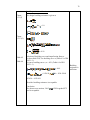
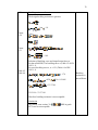
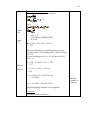
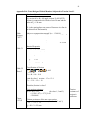
1
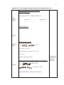
PSZ 19: 16 (Pind. 1/97)
UNIVERSITI TEKNOLOGI MALAYSIA
BORANG PENGESAHAN STATUS TESIS
JUDUL:
DESIGN OF STEEL TRUSS ELEMENT WITH
EUROCODE 3 USING VISUAL BASIC
SESI PENGAJIAN: 2008/2009
Saya
GERARD J.JOEPLIK
(HURUF BESAR)
mengaku membenarkan tesis (PSM/Sarjana/Doktor Falsafah)* ini disimpan di Perpustakaan
Universiti Teknologi Malaysia dengan syarat-syarat kegunaan seperti berikut:
1.
2.
3.
4.
Tesis adalah hakmilik Universiti Teknologi Malaysia.
Perpustakaan Universiti Teknologi Malaysia dibenarkan membuat salinan untuk
tujuan pengajian sahaja.
Perpustakaan dibenarkan membuat salinan tesis ini sebagai bahan pertukaran
antara institusi pengajian tinggi.
** Sila tanda (√)
√
SULIT
(Mengandungi maklumat yang berdarjah keselamatan atau
kepentingan Malaysia seperti yang termaktub di dalam
AKTA RAHSIA RASMI 1972)
TERHAD
(Mengandungi maklumat terhad yang telah ditentukan
oleh organisasi/badan di mana penyelidikan dijalankan.
TIDAK TERHAD
Disahkan oleh
(TANDATANGAN PENULIS)
(TANDATANGAN PENYELIA)
Alamat tetap:
P.O.BOX 319, MENGGATAL
88450, KOTA KINABALU,
SABAH
Tarikh: 4 APRIL 2009
PROF. DR. SHAHRIN MOHAMMAD
Nama Penyelia
Tarikh: 4 APRIL 2009
CATATAN: * Potong yang tidak berkenaan.
** Jika tesis ini SULIT atau TERHAD, sila lampirkan surat daripada pihak
berkuasa / organisasi berkenaan dengan menyatakan sekali sebab dan tempoh
tesis ini perlu dikelaskan sebagai SULIT atau TERHAD.
♦ Tesis dimaksudkan sebagai tesis bagi Ijazah Doktor Falsafah dan Sarjana
secara penyelidikan, atau disertasi bagi pengajian secara kerja kursus dan
penyelidikan, atau Laporan Projek Sarjana Muda (PSM).
“I hereby declare that I have read this thesis and in my opinion this thesis is sufficient in
terms of scope and quality for the award of the degree of civil engineering”
Signature
:
……………………………………………………………..
Name of Supervisor :
PROF. DR. SHAHRIN MOHAMMAD
Date
4 MAY 2009
:
DESIGN OF STEEL TRUSS ELEMENT WITH
EUROCODE 3 USING VISUAL BASIC
GERARD J.JOEPLIK
A report submitted in partial fulfillment of the
requirements for the award of the degree of
Bachelor of Civil Engineering
Faculty of Civil Engineering
Universiti Teknologi Malaysia
4 MAY 2009
ii
I declare that this thesis entitled “Design of Steel Truss Element With Eurocode 3 Using
Visual Basic” is the result of my own research except as cited in the references. The
thesis has not been accepted for any degree and is not concurrently submitted in
candidature of any other degree.
Signature
:…………………………………………….
Name
:
GERARD J.JOEPLIK
Date
:
4 MAY 2009
iii
Special dedication to
my parents and my siblings,
my friends,
and also
my great supervisor Prof. Dr. Shahrin Mohammad
iv
ACKNOWLEDGEMENTS
First and foremost, thanks to the Lord because by His fruitful blessing that I
would have the strength to do this project. Secondly, I would like to thank my project
supervisor, Prof. Dr. Shahrin Mohammad who had guided me from the beginning of this
project until the end of this project despite of his bustling and hustling life as a Dean of
the Faculty of Civil Engineering, Universiti Teknologi Malaysia. Without his tender
help, I am surely will encounter deep problem in accomplishing this project.
Not to forget, I would like to thanks my friend, Dee Aguindrew Gundeh, who
had helped and always be there for me in solving the problems I faced during the
development of this project. Also to all my friends whom had gave me the best moment
and encouragement for the whole year in bringing to the end of the project.
Finally, I would like to express my heartfelt gratitude to my family, for their
endless support. May the mighty Lord grant all of you with His blessing. Thank you so
much.
v
ABSTRAK
Rekabentuk dalam pembinaan menggunakan keluli telah meningkat terutama
sekali negara yang berkembang maju. Kajian ini adalah berkaitan dengan penghasilan
sebuah perisian yang bertujuan membantu pengguna dalam pengiraaan rekabentuk
anggota kekuda keluli dengan mengunakan keluaran terbaru Eurocode 3 EN 1993.
Program yang dihasilkan ialah “Steel Truss Design” dan dihasilkan menggunakan
Visual Basic 6.0. Eurocode 3 telah diimplementasikan ke dalam pengiraan rekabentuk
dan semua hasil pengiraan akan dibandingkan dengan hasil pengiraan secara manual
untuk proses pengesahan. Dengan kepuasan dalam proses pengesahan tersebut, sebuah
jadual kapasiti akan dihasilkan dengan menggunakan perisian tersebut dan kajian
parametrik akan dijalankan. Daripada kajian parametrik tersebut, pengguna boleh lebih
memahami tentang sifat-sifat seksyen keluli. Di akhir kajian ini, boleh disimpulkan,
perisian ini boleh digunakan untuk membantu pengguna untuk merekabentuk anggota
kekuda dengan tepat dan lebih mudah.
vi
ABSTRACT
The designs of construction using steel have been upgraded especially in the well
developed country. This is a study of developing a computer program in order to aid
user to calculate the design of steel truss member using the latest version of Eurocode 3
EN 1993. The program is called Steel Truss Design and developed using Visual Basics
6.0. Eurocode 3 is implemented in the calculation of the design and all results from the
computer program will be compared with the manual calculation. Upon a satisfactory of
the validation process, a capacity table is produced by using the software, and parametric
study is carried out. From the parametric study, designer will be able to understand
more of the properties behavior of section. At the end of the study, it can be conclude
that Steel Truss Design program can be use to help user to design truss member
accurately and easily.
vii
CONTENTS
CHAPTER
1
TITLE
PAGE
TITLE
i
DECLARATION
ii
DEDICATION
iii
ACKNOWLEDGEMENT
iv
ABSTRAK
v
ABSTRACT
vi
CONTENTS
vii
LIST OF TABLES
x
LIST OF FIGURES
xi
LIST OF SYMBOLS
xii
LIST OF APPENDICES
xiv
INTRODUCTION
1
1.1
General
1
1.2
Problem Statement
3
1.3
Objective
4
1.4
Scope of Thesis
4
1.5
Contents of Thesis
5
viii
2
LITERATURE REVIEW
6
2.1
Visual Basic
7
2.1.1
Introduction to Visual Basic
7
2.1.2
The core of Visual Basic
8
2.1.2.1 Event Driven Programming
9
2.1.2.1 Object Oriented Programming
9
Visual Basic Environment
10
2.1.3.1 Visual Basic Window
10
2.1.3.2 Main window
10
2.1.3.3 Form1 and form designer window
10
2.1.3.4 Toolbox
10
2.1.3.5 Project Explorer window
11
2.1.3.6 Properties window
11
2.1.3.7 Form layout window
11
2.1.3.8 Code window
12
2.1.3
2.2
Introduction to Eurocode 3
12
2.3
Steel design
14
2.3.1
Basic of design
14
2.3.2
Steel Truss Design
15
2.3.3
Design of Steel Truss Using Eurocode 3
16
2.3.3.1 Design of compression member with
axially loaded
16
2.3.3.2 Design of tension member with axially
loaded
2.4
3
Conclusion
28
32
METHODOLOGY
33
3.1
Introduction
33
3.2
Preliminary study
34
3.3
Flow chart establishment
35
3.4
Program Review
36
ix
4
5
6
3.5
Developing program
36
3.6
Checking of program
36
3.7
Program debugging
37
3.8
Program validation
38
3.9
Result validation
38
3.10
Parametric Study
40
3.11
Conclusion
41
USER MANUAL
42
4.1
Introduction
42
4.2
Steel Truss Design
43
4.2
Steel Truss Design main form
44
4.2
Result form
48
4.2
Parametric study form
50
4.2
Conclusion
51
RESULTS ANALYSIS AND DISCUSSION
52
5.1
Introduction
52
5.2
Parametric Study
53
5.3
Discussion
60
5.4
Conclusion
61
CONCLUSION AND RECOMMENDATION
62
6.1
Conclusion
62
6.2
Recommendations
63
REFERENCES
APPENDIX
65
66-83
x
LIST OF TABLES
TABLE NO.
2.1
TITLE
PAGE
Nominal values of yield strength fy and ultimate tensile
strength fu for hot rolled structural steel
2.2
(continued) Nominal values of yield strength fy and ultimate
tensile strength fu for hot rolled structural steel
2.3
19
Maximum width-to-thickness ratios for compression
parts (Sheet 1 of 3)
2.5
18
Maximum width-to-thickness ratios for compression
parts (Sheet 1 of 3)
2.4
17
20
Maximum width-to-thickness ratios for compression
parts (Sheet 3 of 3)
21
2.6
Selection of buckling curve for a cross-section
25
2.7
Reduction factors β2 and β3
29
3.1
Steel Truss design 1: Circular hollow section truss
member (Compression)
3.2
Steel Truss design 2: Square hollow section truss
member (Compression)
3.3
40
Steel Truss design 5: Equal section truss member
(Bolted tension member)
3.6
39
Steel Truss design 4:Equal section truss member
(Bolted tension member)
3.5
39
Steel Truss design 3: Square hollow section truss
member (Compression)
3.4
39
40
Steel Truss design 6: Equal section truss member
(Welded tension member
40
xi
LIST OF FIGURES
FIGURE NO.
TITLE
PAGE
2.1
Main window for Visual Basic
2.2
Truss elements
15
2.3
Buckling curves
26
2.4
Angles connected by one leg
30
4.1
Interface of the opening window ‘opening form’
43
4.2
Truss info tab
45
4.3
Section properties tab
46
4.4
Bolted connection for angles form
47
4.5
Check design tab
48
4.6
Calculation and result interfaced
49
4.7
Capacity Table
50
5.1
Capacity table for compression Structural Tee
Cut from Universal Beam.
5.2
54
Capacity table for compression Square Hollow
Sections.
5.4
53
Capacity table for compression Structural
Tee Cut from Universal Column.
5.3
9
55
Capacity table for compression Rectangular Hollow
Sections.
56
5.5
Capacity table for Compression Equal Angles.
57
5.6
Capacity table for Compression Unequal Angles.
58
5.7
Capacity table for Compression Circular Hollow Sections.
59
xii
LIST OF SYMBOLS
A
-
Area
Anet
-
Nett area
b
-
Width of section
β2
-
Reduction factor for two bolts
β3
-
Reduction factor for three bolts or many.
d
-
Depth between fillets
d0
-
Hole diameter for a bolt, a rivet or a pin.
e2
-
The edge distance from the centre of a fastener hole to the
adjacent edge of any part, measured at right angles to the
direction of load transfer,
E
-
Modulus of elasticity
fy
-
Yield strength
fu
-
Ultimate tensile strength
h
-
Depth of section
hw
-
Height of web
Iy
-
Second moment of area (Y-Axis)
Iz
-
Second moment of area (Z-Axis)
NEd
-
Design value of the compression force
Nc, Rd
-
Design resistance to normal forces of the cross-section for
uniform compression
Nt, Rd
-
Design values of the resistance to tension forces.
Npl, Rd
-
Design plastic resistance to normal forces of the gross
cross section
Nu, Rd
-
Design ultimate resistance to normal forces of the net
cross section at holes for fastener
Ncr
-
Elastic critical buckling force
Nb, Rd
-
Cross-section buckling resistance
xiii
p1
-
Spacing between canters of fasteners in a line in the
direction of load transfer,
r
-
Root radius
tf
-
Flange thickness
tw
-
Web thickness
Wpl, y
-
Plastic modulus (Y-Axis)
Wel, y
-
Elastic modulus (Y-Axis)
γM
-
General partial factor.
xiv
LIST OF APPENDICES
APPENDIX NO.
TITLE
PAGE
A-1
Flow chart for compression member
68
A-2
Flow chart for tension member
73
B-1
Truss Design of Member Subjected to Compression
Load 1
B-2
Truss Design of Member Subjected to Compression
Load 2
B-3
81
Truss Design of Bolted Member Subjected to Tension
Load 2
B-6
79
Truss Design of Bolted Member Subjected to Tension
Load 1
B-5
77
Truss Design of Member Subjected to Compression
Load 3
B-4
75
83
Truss Design of Welded Member Subjected to Tension
Load
85
CHAPTER I
INTRODUCTION
1.1
General
Human civilization in the construction area has been develops majorly. As the
countries experienced a steady progression, one of the major industries benefitting from
this development is the construction industry. Besides concrete, steel structure could
provide better choice for construction present needs especially when there is shortage of
cement, influx of the unskilled labor and the stressed of achieving high quality structure
by the government. (Ahman Fikri Hussein and Mohd Zulkifli Ghazalie, 1996)
By considering the vast development of steel construction, more material of steel
is need. Some high quality used steel is recycled and some produced. Steel is produced
b refining iron ore and scrap metal together with appropriate fluxing agents, coke (for
carbon), and oxygen in high-temperature furnaces to produce large masses of pi iron.
Steel is the most widely used metal as a construction material due to the combination of
several factors such a high strength, durable, good ductility, high stiffness and relatively
cheap if taken into account speedy in construction time. (Steel Technology Center,
Universiti Teknologi Malaysia)
2
Malaysia, as one of the fastest developing country in the Southern Asian region
did not really used steel in construction until mid 80’s. by then, Steel started to be used
mainly for industrial buildings such as factories and warehouse. Presently, there are few
companies that are involved in steel production for example Parana Steel Sdn.Bhd, BHP
Lysaght Malaysia, Antara Steel Sdn.Bhd, and Amalgamated Industries Steel Sdn.Bhd.
There are several steel buildings in Malaysia, such as Menara Promet, Menara PNB,
Dayabumi, and some used steel as the main frame system which is Weld tower and also
The Petronas Twin Tower Which utilizes steel beams and metal decking floor system.
(Ahman Fikri Hussein and Mohd Zulkifli Ghazalie, 1996)
Apparently the prospect of steel construction in Malaysia seems to bright in the
future. More design of steel structural will be studied. In structural design, its involved
deep understanding, long calculation and consideration while designing structure. This
will affect the cost, time and human resource involved in the design and analysis. The
development of computer software program for structural design had help many
designer in reducing time and cost, ensure consistency and accuracy in calculation and
provide easy understanding for new designer. (Hii How Nguong, 2006)
As what we can see in the design practice especially Malaysia, almost all
designers are still using the British Standard (BS). While BS 5950 is still being used in
steel structural design and analysis, the emergence of Eurocode 3 had it own role for
providing more practical and economical design. EN Eurocode will replace British
Standard in the future. So, it is very important Eurocode 3 to be put into practice in the
industry throughout Malaysia.
3
1.2
Problem Statement
Since publication in November 2005, Eurocode had been given a National
Standard status, any conflicting National Standards will be withdrawn by March 2010.
The new code will be replacing the old code which mostly refers to British Standard
(BS) code of practice (European Committee For Standardization, 2005). In Malaysia,
almost all company and education institution is still using BS. Although many
structural engineering still practicing British Standard code, it is very important to learn
and implement new code in order to stay advanced.
Not only the standard matter in this project, but most of the design and analysis
of building involved a very long calculation, and it took time to be completed. One best
solution for this matter is to build a computer software which able to calculate faster,
accurate, and consistence. It will not only provide easier way to design and analysis but
also will give instant experience of engineering experience.
For this project, there is software which is developed by previous students. The
program is called Steel Structure Design (SSD) which it is developed using Visual Basic
6. But, the software is out-dated since code used for the design of structure is ConciseEurocode 3 (C-EC 3). So, there is still need to create a new software which is using the
latest EN 1993 Eurocode 3.
4
1.3
Objective
With the purpose to cope with the problem, there are four main objectives had
been set in this study:
i.
To create software that able to calculate for compression and tension
members of the truss design using Eurocode 3 EN 1993-1-1.
ii.
To provide a parametric study in the software in order to compare the
behavior of the cross sections.
iii.
To produce a member capacity table for truss member subjected to
axially compression load.
1.4
Scope of Thesis
In order to ensure the objectives are achieved, several scopes needed to be stated
so that the research does not turn aside from the real purpose of the study. In this
project, the study will only be focused on truss design. The software will be developed
for the design of truss member. Furthermore, the concern of the design of truss member
will only consist of compression and tension member. There will be no shear resistance
or bending resistance matters. The design will be about calculation for the cross section
resistance and buckling resistance of the truss member.
5
The study of truss and the design will be fully based on EN 1993 Eurocode 3
2005, the latest version of steel design in Eurocode. All of the cross section of members
will be base on the Eurocode 3 table of properties.
The software will be developed by using Visual Basic 6 as the programming
code. Microsoft Access will be use for the database of the tables of properties.
The software will only mean to design for hot rolled sections. Moreover, all
connections between truss members are assumed to be pin connected. At this moment,
this computer program can only carry out the design of each truss member. The design
approach of the software also will not include the design of slender steel segment and
high shear steel segment.
1.5
Contents of Thesis
In this report, there will be five chapters prepared. Chapter 1 is the introduction
chapter which contain brief introductory about the research, the problem of the research,
the aims of the study and also the scope of research.
In Chapter 2 concern will be stressed on the literature review. It contains some
article of the Visual Basic program, the design and analysis of steel truss and also EN
1993 Eurocode 3.
In Chapter 3, the procedure for conducting this study and all methods used are
highlighted. For Chapter 4 emphasize on the analysis and measurement work done on
the accuracy of the program. For chapter 5, is the conclusion for the whole project and
recommendation for future research.
CHAPTER II
LITERATURE REVIEW
For every research study, there is a lot of review need to be done. The
literature review of the study is divided into 3 main sections. The first section is about
the programming language, Visual Basics 6.0. It contains brief introduction, concept
and the environment of visual basics 6.0. Then the second section is concern on the
Eurocode 3. The third section is about the steel truss design which consists of the step
of design following the code of Eurocode 3.
2.1
Visual Basic
2.1.1
Introduction to Visual Basic
The program used to create the software is Visual Basic. Visual Basic is a
programming language which provide good introduction to window programming. The
integrated development environment (IDE) allow user to create fully fledged windows
7
applications with the minimum of effort and time. The window of the application can be
drawn on the screen; therefore user can always see what the output application will look
like without having to guess according to the code written for the program. Visual
Basics avoid the long-winded trial and Error approach to designing screen displays of
the older programming languages. (Stephen Morris, 1997)
Visual Basic had been developing together with other programming language.
Microsoft first released Visual Basic in 1987. It was the first visual development tool
form Microsoft, and it was to compete with C, C++, Pascal and other well-known
programming languages. From the start, Visual Basic was not well-known until the
release of Version 2.0 that people realized the capability of the language, and with
release of version 3.0 it had become a phenomenon and fastest-growing programming
language on the market. Visual Basic continue to grow as a major programming tool
and the latest released is Visual Basic.net which superseded Visual Basic 6.
(startvbdotnet, 2004-2007).
2.1.2 The core of Visual Basic
For being a well established programming language, some of the important features
of Visual Basic are the Object Oriented Programming (OOP) and Event Driven
Programming which will briefly covered later. Other than that is the ability to allow
programmer to develop a program which consist of Graphical User Interface (GUI).
Now instead of the cryptic C:> prompt that DOS users have long used, desktop now
enhanced with icons and with programs that use mice and menus (Gary Cornell, 1997)
8
2.1.2.1
Event Driven Programming
One of the Visual Basic feature is Event Driven Programming. Programs
written in Visual Basic are called Event Driven Programming, An event is something
that happens that the computer can detect typical events include:
a) Clicking a mouse button
b) Typing a character on a keyboard
c) Deleting or changing a value
When an even occurs, the program will execute the programming statements
related with that programmed event, called as event procedure. When that event
procedure completes execution, control returns to be application even-driven programs
give the user a lot of control over the action of application.
2.1.2.2
Object Oriented Programming
Another special feature of Visual Basic is Object Oriented Programming
(OOP) language. A major factor in the invention of object oriented is to remove some of
the flows encountered with procedural approach. In OOP, data is treated as critical
element and does not allow it to flow freely. It bounds data closely to the functions that
operate on it and protects it from accidental modification from outside function. OOP
allows decomposition of a problem into an object and then build functions around the
object. The major advantage of OOP is code reusability. (startvbdotnet.com, 20042007)
9
2.1.3
Visual Basic Environment
When Running a Visual Basic Program, the new Project Window will appear.
This dialogue box effectively provides a menu for deciding what work is going to be
done. To start creating program, the standard.exe should be clicked twice.
2.1.3.1
Visual Basic Window
Figure 2.1: Main Windon for Visual Basic 6
2.1.2.3
Main Windows
10
The main window contains the entire element that can be found in a windows
application. The title bar contains the name of the current project (initially project 1)
and the usual buttons for minimizing, maximizing and closing window, and the menu
bar includes eight pop down men. The toolbar contains a number of icons that provide
shortcut to the most frequently used Visual Basic operations. On the night two sets of
figures provide information about any selected Visual Basic element.
2.1.2.4
Toolbox
Most Programs contains a number of different objects such as command button,
text boxes, and labels and so on. These are call control and it can be added to
application by dragging them from the toolbox.
2.1.2.5
Form1 and form Designer window.
To start off, Visual Basic supplies a single form called Form 1. This form will
be renamed and resized when developing an application. Other forms will be added as
required.
11
Project Explorer window
For each window in final application, there is a corresponding Visual Basic form,
and each form has its own file on disk. At least one file containing the program code for
the application and if the forms use an third party tools, those will be held in additional
files. All files go together to make up the project form which the application is built.
2.1.2.6
Properties window
Each form and each control on a form has a set of properties. These determine
the appearance of the form or control and the way in which it behaves. The properties
window displays the properties for the selected form on control, and allows you to
change them.
2.1.2.7
Form layout window
The form layout windows helps user to determine the initial position of the forms on the
screen when application is run.
12
2.1.2.8
Code window
Code window only being call out when programmer are ready to type Visual Basic
program statement for project. Like the form window, it is sizable and movable. Each
form has its own code window. (Stephen Morris, 1997)
2.2
Introduction to Eurocode 3
EN 1993 Eurocode 3 is use to design of building and other civil engineering
works in steel. It follows the principles and requirements for the safety and
serviceability of structures, the basis of their design and verification that are given in EN
1990 – Basis of structural design. EN 1993 Eurocode 3 is concerned with the
requirement for resistance, serviceability, durability and fire resistance of steel structure.
(CEN, 2005)
Work began on the set of structural Eurocodes in 1975. For structural steelwork, the
responsible committee, under the chairmanship of Professor Patrick Dowling of Imperial
College London, had the benefit of the earlier European Recommendations for the
Design of Structural Steelwork, prepared by the European Convention for
Constructional Steelwork in 1978. Apart from the obvious benefit of bringing together
European experts, preparation of this document meant that some commonly accepted
design procedures already existed. E.g. the European column curves. Progress was,
however, rather slow, and it was not until the mid 1980s that the official draft
documents, termed ENVs, started to appear. The original, and Unchanged, main
grouping of Eurocodes, comprises 10 documents: EN 1990, covering the basis of
structural design, EN 1991, covering actions on structures, and eight further documents
essentially covering each of the structural materials (concrete, steel, masonry etc). (L
Gardner and D A Nethercot, 2005)
13
Eurocode 3 EN 1993 is wider in scope compared to other EN Eurocode due to the
diversity of steel structures, the need to cover both bolted and welded joints and the
possible slenderness of construction. EN 1993 has about 20 part covering common
rules, fire design, bridges, building, tanks, silos, pipelined piling, crane supported
structures, towers and masts, chimneys etc. (Eurocodes.Jrc.ec.europa.eu, 2005)
EN Eurocode 3 is intended to be used in conjunction with,
1. EN 1990: Eurocode – Basis of Structural Design;
2. EN 1991: Eurocode 1 – Actions on structures;
3. ENs, ETAGs and ETAs for construction product relevant for steel structures;
4. EN 1090: Execution of Steel Structures - Technical requirements.
5. EN 1992 to EN 1999 when steel structures or steel components are referred
to (Eurocodes.Jrc.ec.europa.eu, 2005)
In Eurocode 3 EN 1993, the design of steel structures shall be in accordance
with the general rules given in EN 1990 with some supplementary provisions in the
code. The basic requirements of EN 1990 section2 should be satisfied where limit state
design is used in conjunction with the partial factor method and the load combinations
given in EN 1990 together with the actions given in EN 1991. The rules for resistances,
serviceability and durability given in the various parts of EN 1993 should be
given.(CEN, 2005)
14
2.3
Steel Design
2.3.1
Basic Of Design
The design of a structural member required the selection of the cross section that
will safely and economically resist the applied load. Economically usually means
minimum weight of steel which correspond to the cross section with smallest weight per
meter, which is one of the smallest cross sectional area. (William T.Segui)
At the start of structural design, an engineer must make a number of basic
choices, among them being the materials to be used in construction and the structural
system in which they are to be used; the number of material commonly used in primary
structural systems is limited. A list that includes steel, reinforced and unreinforced
masonry (concrete and other) wood and aluminum would be almost exhaustive for most
definition of primary structures. (SOL.E.Cooper, 1985)
Limit states design provides the basic framework within which the performance
of the structure can be assessed against various limiting conditions. When formulating
procedure nowadays, it is customary to do so in a way which recognized the inherent
variability of loads, materials, construction practices and approximations made in
design; this usually involves the use of some concept of probability. The limiting
conditions are normally grouped under two headings. Ultimate or safety limit states and
serviceability limit states. (David A.Nethecot, 2001)
Other consideration, such as ease of construction, may ultimately affect the
choice of member size, the process begins with the selection of the lightest cross section
shape that will do the job. After that engineer must decide on hot to construct if safely.
(William T.Segui, 2003)
15
2.3.2
Steel Truss Design
Trusses and lattice girders are structures composed of triangulated members
joined together at their end points. Welding or bolting of the member of by using gusset
plate forms the joint connections. Pitched trusses are usually used for roofs while
parallel chord lattice girders are employed to support roofs, floor and for bridges.
Trusses can be delivered to construction site as one complete unit, as several units or
even as individual elements they may provide added advantages.(Steel Technology
Center, Universiti Teknologi Malaysia)
Figure 2.2: Truss Elements
Generally, truss element can be divided into three categories, Top cord, Bottom
cord and inner member or web cord (refer to figure 2.3.2). When a truss is subjected to
a given loading, the force developed in each member is either tensile or compressive and
in certain cases even bending. In order to design the members and the connection of the
truss, it is necessary to calculate these forces. (Hii How Nguong, 2006)
The use of rolled hollow sections for trusses provides a far more efficient use of
material as the buckling strengths are higher as radii of gyration are larger and lateral
torsional buckling is either non-existent in the case of square or circular sections, or the
effects are much reduced for rectangular sections. (Lawrence Martin and John Purkiss,
2008)
16
2.3.3
Design of Steel Truss using Eurocode 3
2.3.3.1 Design Compression members with axially loaded
For compression member, design is made with the concern of both cross section
resistance and buckling resistance. The procedure of designing a compression member
is as below:
i.
For the Ultimate Limit State, the design axial compressive force NED for
the relevant load case is determined using partial safety factors.
Fy = 1.35Gk + 1,5Qk
ii.
Select steel grade and material property. (EN 1993-1-1 Table 3.1)
17
Table 2.1: Nominal values of yield strength fy and ultimate tensile strength fu for
hot rolled structural steel
Table 2.2: (continued): Nominal values of yield strength fy and ultimate tensile
strength fu for structural hollow sections
18
iii.
Classify Cross Section in compression. (EN 1993-1-1 Table 5.2)
19
Table 2.3: Maximum width-to-thickness ratios for compression parts (Sheet 1 of 3)
20
Table 2.4: Maximum width-to-thickness ratios for compression parts (Sheet 2 of 3)
21
Table 2.5: Maximum width-to-thickness ratios for compression parts (Sheet 3 of 3)
22
iv.
Resistance of cross section checking
For tension force at each cross section should satisfy:
: Clause 6.2.3(1)
For section with holes the design tension resistance Nt,Rd should be taken
as the smaller of :
a) The design plastic resistance of the gross-section
: Clause 6.2.3 (2)
b) The design ultimate resistance of the net cross-section at holes for
fasteners.
: Clause 6.2.3(4)
The clause 6.1 Note 2B partial factors γMi for building may be defined in
the National Annex, the following numerical values are recommended for
buildings:
For design value of compression force at Ned at each cross-section should
satisfy:
: Clause 6.2.4 (1)
The design resistance of the cross section for uniform compression Nc,Rd
should be determined as follows:
23
: Clause
6.2.4 (4)
The clause 6.1 Note 2B partial factors γMi for building may be defined in
the National Annex, the following numerical values are recommended for
buildings:
v.
Determine the buckling length L for each axis
By referring to BB.1 Flexural buckling of members in triangulated and
lattice structures.
BB.1.1 General
(1)B For chord members generally and for out of plane buckling of web
member, the buckling length Lcr may be taken as equal to the system
length L, see BB.1.3(1)B, unless a smaller value can be justified by
analysis.
(2)B The buckling length Lcr of an I ar H section chord member may be
taken as 0,9L for in-plane buckling and 1,0L for out-of plane buckling,
unless a smaller value is justified by analysis.
(3)B Web members may be designed for in-plane buckling using
buckling length smaller than the system length, provided the chords
supply appropriate end restraint and the end connection supply
appropriate fixity (at least 2 bolts if bolted)
(4)B Under these condition, in normal triangulated structures the
buckling length Lcr of web members for in-plane buckling may be taken
as 0,9L, except for angle section, see BB.1.2 and BB.1.3
vi.
Determine the slenderness for each axis
24
For Flexural buckling refer to 6.3.1.3, the non-dimensional slenderness λ
is given by:
:Clause 6.3.1.3(1)
Where:
Lcr is buckling length in the buckling plane considered
ii is the radius of gyration about the relevant axis, determined using the
properties of the gross cross section
Note B for elastic buckling of components of building see Annex BB.
vii.
Select the appropriate buckling curve for each axis, for the type of cross
section and thickness of steel
For Flexural buckling the appropriate buckling curve should be
determined from Table 6.2 and Table 6.4 to find for χ or refer to clause
6.3.1.2.
25
Table 2.6 : Selection of buckling curve for a cross-section
26
Figure 2.3: Buckling curves
Besides using the buckling curve, for easy programming of the software,
another alternatives approached was taken to calculate the value of
reduction factor, χ. The method is by using the equation 6.49 in clause
6.3.1.2.
27
α is an imperfection factor
Ncr is the elastic critical force for the relevant buckling mode based on the
gross cross sectional properties. The Ncr value for flexural buckling can
be calculated by using this equations. (L Gardner and D A Nethercot,
2005)
viii.
Determine the buckling resistance
From the value of χ obtained, used equation from clause 6.3.1(3) to
determine the buckling resistance.
: clause 6.3.1(3)
Where χ is the reduction factor for the relevant buckling mode.
ix.
Compare the buckling resistance with the design axial force. If Nb,Rd >
NEd then the selected section is satisfied. Refer to clause 6.3.1.1
2.3.3.2 Design Tension members with axially loaded
The biggest consideration that must be given for tension member in
structural steel is the end connections due to bolt holes and the possible
occurrence of stress reversal causing the member to buckle as a compression
28
member. It is crucial to check on the possible reduction of the resistance at the
end connection.
The step of analysis is as following:
i.
Step i to iii will be the same step of tension member design.
ii.
Classify the section in tension fu from table 3.1 in clause 3.2.3
iii.
Identify the diameter of bolt (D), bolt holes (do) and amount of bolt.
iv.
Identifying net area, Anet
Anet = Ag - Σdot
Anet is the net area of the angle. For an unequal-leg angle connected by
its smaller leg. Anet should be taken as equal to the net section area of an
equivalent equal-length angle of leg size equal to that of the smaller leg.
v.
Determine the design plastic resistance of the gross section, NplRd
: clause 6.2.3 (2) (a)
vi.
Determine the design ultimate resistance of the net section.
For member without bolt connection at end
: clause 6.2.3(2)(b)
29
For angles connected by one leg refer to clause 3.10.3 from EN 1993-1-8
2005
Where:
β2 and β3 are reduction factors dependent on the pitch p1 as given in
Table 3.8. For intermediate values of p1 the value of β may be determined
by linear interpolation;
Table 2.7 Reduction factors β2 and β3
30
Figure 2.4: Angles connected by one leg
Anet is the net area of the angle. For an unequal-leg angle connected by its
smaller leg, Anet should be taken as equal to the net section area of an
equivalent equal-leg angle of leg size equal to that of the smaller leg.
vii.
Capacity design of plastic resistance Npl,Rd should be less than the design
ultimate resistance of the net section at fasteners hole Nu,Rd
Nu,Rd < Npl,Rd
viii.
Section will satisfy if Nt,Rd > NEd
31
2.4 Conclusion
This Chapter is about the literature review of the research, beginning with the
introduction of Visual Basics, cores of Visual Basics and some critical function and
behavior of Visual Basic. Next is the brief introduction about Eurocode 3 and followed
by basis of design. Then there is review on analysis of truss using stiffness method and
the steps of design truss with three condition. The conditions are axially loaded of a
compression member, axially loaded of a tension member and also bending moment
with axially loaded. The some of the review are enclosed with some useful tables and
figures. But for easier understanding, refer the flowchart in the Appendix section.
32
CHAPTER III
METHODOLOGY
3.1
Introduction
This section discusses the methodology of the research. The main purpose of this
research is to create new design software for truss design using the Eurocode3 approach
of EN 1993-1-1 with Visual basic (VB) as the programming language.
To achieve such aim, one must have strong knowledge about computer
programming. Not only that, but also to have deep understanding of the design of steel
truss with Eurocode 3 standard.
As what had been learned before, the basic of VB programming is very useful but
revision and acquiring of additional knowledge still need to be done. Supplementary of
VB skills had to be practice too. Since the new code will be implemented in the
program, one must master of the subject and have to work on many examples to get use
of the code. Many references and practice had to be done in order to accomplish the
project.
This chapter will cover the preliminary study, flowchart establishment as a guide for
programming and convenient of reference, software review on the strengths and
weakness etc as a guideline for developing a new software, term and parameter check,
33
program check to identify the mistakes and imperfectness, form and code update to fix
error and to change the standard of design and analysis, final validation for last
inspection and also the parametric study to enhance the ability of the new software.
3.1 Preliminary Study
The first step of this study is to understand design and analysis of steel truss
structure using Eurocode 3 and also Visual Basic Programming. The Eurocode 3
Standard EN 1993-1-1:2005 and other parts will be studied thoroughly. Many books,
articles and previous write-up about Eurocode 3 will be reviewed for better
understanding of the code. Worked examples have to be collected from various resource
e.g. books, internet and previous thesis. Then the examples have to be checked and redo
as a practice. The examples also will be updated with the latest version of Eurocode 3.
Not only worked examples for Eurocode 3 but also Visual basics samples. It is
important to collect many samples of Visual Basic program will be used for revision of
programming. This is crucial for programming steps not all function was learned
previously. For developing the software, one must know the how to connecting VB
program to the Microsoft Access database with the Structured Query Language (SQL)
method and also other function of VB.
The study of SSD program is also another method of the research. Since the
program was developed by previous students, it provides the best guide and reference to
create a new program. Since the copy software program is not provided due to
copyright restriction, reference and guidance was obtained from the previous thesis. The
thesis produce by Hii How Nguong contain user manual and some of the screenshot and
explanation of the program functions. The other books written by Lee Chun Haw and
34
others were also useful for references. The writing will be studied and their
recommendation is important to be considered.
Since this study is about developing software program of steel element design
using the latest practice of Eurocode 3 and most of the reference of thesis are using the
older version of the code e.g. DD ENV 1993, and C-EC3, it is very important to
understand Eurocode 3 especially EN 1993-1-1 before developing the software. The
flow of calculation for design for the code need to be understood as any difference need
to be detected from the previous code before updating with the new Eurocode. For easy
reference flowchart for the design and analysis of truss will be constructed.
3.2 Flow Chart Establishment
To make a proper planning before developing the software, it is very important
to sketch a flow chart. It is a good practice for most programmers regardless of
language of programming used because flowchart gives the big picture about how the
software is going to work. A flowchart consists of special geometric symbols
connected by arrows. Within each symbol, there will be a phrase representing the
activity of the steps. The shape of the symbol indicates the type of operation.
Flowchart also provides easier understanding of the calculation. A flowchart
will be established according to the steps of designing trusses. The flowcharts from the
work of previous students will be studied and new one will be constructed with
implementation of the new code. From here, comparison will be done in order to know
the difference of the steps of the older flowchart with the new one. This will help to
upgrade the software. Flowchart of the procedure of designing steel truss is attracted at
Appendix A-1 and Appendix A-2.
35
3.3 Program Review
After studying the standard of Eurocode 3, Visual basic and also established a
new flowchart, the next step will be review on the SSD program. Since the copy of
SSD program could not be obtained due to the copyright restriction, the SSD program
can only be study by referring to the user manual of the previous thesis with the same
title which is “Analysis and Design Steel Truss Element with Eurocode 3 using Visual
Basics” by Hii How Nguong, 2006. From the review, certain criteria could be obtain
such as the interface of program, the parameter of consideration, the flow of program,
display of result and parametric of study. The function and flow of the program need
also to be fully grasped in hand as this will help in changing and updating the program.
Review of the software will be done to identify on some properties like strengths,
weakness, and opportunities of upgrading, and threats that might endanger the software.
By detecting such properties, the benefit can be continued for the new software and the
weakness can be improved.
3.4 Developing program
After reviewing, check the program source, coding and form using VB
programming software. The next step is to develop the software from the root. Before
proceeding into the Visual Basics, a sketch of the program interface form, labeling of
object and listing of variables is done to give the overall picture of the new program.
When starting with VB program, all new interface of program is created, object
such as text box, label, picture box, command button, combo box, combo list and many
more were named and arranged in the presentable way into the form. All variables are
36
defined in the coding page. It is very important to arrange the object by following the
sequence of design as this will help user to insert input accordingly.
Through the whole process of program developments, some problem
encountered especially for the method of connecting the program into the table
properties database and also when programming for the parametric study using the array
control.
3.5 Checking of Program
The proceeding step is to do the checking of program which is including the term
and parameter check, and any troubleshooting of the program. Checking can be done by
test running the program. As soon as the term and parameter or troubleshooting are
identified, they ought to be fixed and retest few times until it run smoothly.
This process could be done in few level of checking. The first level is to do the
checking while doing the coding which is very helpful to prevent error in the initial state
of developing the program. The second level of checking is done when the software had
been completed. This checking is important to avoid error and to ensure the program run
according to what is required. Next checking is when there is amendment of the
program. Checking ought to be done after changes of the program so that it still runs
smoothly.
It is advisable to do program checking few times, to will ensure there are no
mistakes or program bugs that might prevent from running perfectly. When program
check had completed, the next step will be program debugging.
37
3.6 Program Debugging
Test running on the program will be done in order to look for errors and bugs.
As if it appeared to have errors and bugs, fixing and debug will be made, VB is
equipped with a very strong debugging function. It enable programmer to find mistakes
just by a single click on the debug button.
The debugging will be done after each changes made to the software with the
intention of finding errors immediately. This process also can avoid confusion and
multiple errors which can occur when debugging is done after completely changing the
coding of the whole program. After errors are fixed, the next step will be the validating
the accuracy of the program.
3.7 Program Validation
After debugging, the program might be able to run and do the calculation, but it
is very important to check on the validity of the result calculated by the program. The
program may not have code programming errors, but the result could still be incorrect
due to wrong equations, value of fix variables, flow of calculation and more.
Program validation can be made by comparing the result given by the program
with the result calculated manually. If variation of result exists, checking affixing will
be made. Another efficient way of checking the validity and fixing of the program is by
using the toggle breakpoint which allows the programmer to set a point of break while
the program is running. The program will show every expression value or calculated
value in each line. Any error could be identified easily and fixing could be done on the
38
spot. After validating the result of the program and fixing error, we can conclude that
the program is reliable.
3.7.1
Result Validation
All result displayed by the software will be compared with the manually
calculated result in order to validate the result of the program. Both results are tabulated
as below with the percentage of different.
Table 3.1: Steel Truss design 1: Circular hollow section truss member
(Compression)
Section
Compression Resistance
Buckling Resistance
Manual
calculation
2026.75 kN
1836.54 kN
Program
Calculation
2026.75 kN
1836.54 kN
% Diff.
0.0
0.0
Table 3.2: Steel Truss design 2: Square hollow section truss member
(Compression)
Section
Compression Resistance
Buckling Resistance
Manual
calculation
88.00 kN
33.27 kN
Program
Calculation
88.00 kN
33.27 kN
% Diff.
0.0
0.0
39
Table 3.3: Steel Truss design 3: Square hollow section truss member
(Compression)
Section
Compression Resistance
Buckling Resistance
Manual
calculation
88.00 kN
33.27 kN
Program
Calculation
88.00 kN
33.27 kN
% Diff.
0.0
0.0
From the table 3.1, table 3.2, and table 3.3, the results obtained by using the
program and the manually calculated are same. Therefore, the computer software is
proven to be able to design compression member of truss
Table 3.4: Steel Truss design 4:Equal section truss member (Bolted tension
member)
Section
Compression Resistance
Buckling Resistance
Manual
calculation
84.98
36.39 kN
Program
Calculation
84.98 kN
36.39 kN
% Diff.
0.0
0.0
Table 3.5: Steel Truss design 5: Equal section truss member (Bolted tension
member)
Section
Tension Resistance
Ultimate tensile design
resistance
Manual
calculation
157.30 kN
84.28 kN
Program
Calculation
157.30 kN
84.24 kN
% Diff.
0.0
0.0
From the table 3.4 and table 3.5, the results obtained by using program and the
manually calculated are same. Therefore, the computer software is proven to be able
to design tension member of truss.
40
Table 3.6: Steel Truss design 6: Equal section truss member (Welded tension
member)
Section
Tension Resistance
Manual
calculation
640.75 kN
Program
Calculation
640.75 kN
% Diff.
0.0
From the table 3.6, the results obtained by using program and the manually
calculated are same. Therefore, the computer software is proven to be able to design
welded tension member of truss.
3.8 Parametric Study
After the validation of the result, the next step of this study is to carry out a
parametric study by producing and analyzing the capacity table. The capacity table is
very useful when designing it is produced by using the method of array in VB. The
created software will do repetition calculation for different size or cross section to obtain
the design capacity of the section with specific length. This action will be done for
member subject to compression only.
41
3.9
Conclusion
To achieve the objectives of the study, few steps of methodology need to be
completed. Begin with gathering the information about EN eurocode 3 and learning to
program using VB. Then establish the flowchart to have an overview of the procedure of
design of steel truss. Next, review the SSD program to get to know the program as
guide and references. Then create new software by adopting the EN Eurocode 3
standard into the program. Last but not least is to validate the reliability of the program.
In addition, parametric study will also be made in order to identify and determined the
relationship between involved parameter.
42
CHAPTER IV
USER MANUAL
4.1
Introduction
Steel Truss Design is a simple design program that enable user to design a steel
truss element which is consist of member subjected to compression and tension. This
software is developed using Microsoft Visual Basics 6.0. Another part of this software
is the automated capacity table program which only focuses on the member subjected to
compression.
The program start with a opening form in every of it execution. The form is
shown in Figure 4.1 below. From this form, user can choose to run the design of steel
truss or the parametric study. Click the ‘Next’ button to continue.
43
Figure 4.1 Interface of the Opening Window. ‘Opening form’
4.2
Steel Truss Design
In short, Steel Truss Design of the software is able to perform the following tasks when
deal truss design:
a)
Design of compression member of steel truss according to Eurocode 3
i. Section classification
ii. Cross section resistance checking which include the design resistance of cross
section for uniform compression force value.
iii. Buckling resistance checking which include the design buckling resistance of
the compression member.
b)
Design of tension member of steel truss according to Eurocode 3
i.
Section classification
44
ii.
Cross section checking which include the design tension resistance of the
cross section and the design ultimate resistance of the net cross-section at holes
for fasteners.
c)
Carry out a parametric study for the compression element of truss.
4.3
Steel Truss Design Main Form
When the Steel Truss design is chosen and button ‘Next’ was clicked, a new
form that is the main form will appeared as in Figure 4.2. The main form contain three
tabs that is Truss Info, Section Properties and Check Design. Each of the tabs contain
all the properties that need to be inserted before the design process.
As the Truss Info tab, it contains member properties, member info and
connection. Member properties are the area where user can choose whether member is
subjected to compression or tension, input all the loading and yield strength and
ultimate tensile strength. As for this project the maximum moment and Shear force are
not usable yet.
Next is the connection, for compression member, connection is not a concern
so it is not enabled. But for tension member, it is enabled and user may choose to use
bolt or welded. If use choose bolt, then the size of bolt is enabled to be chosen. In the
member info frame, user may input the effective length value and also the location of the
member.
45
Figure 4.2 Truss Info tab
In section properties tab as in figure 4.3, user may choose the desired type of
cross sections. There are seven types of cross section available in this software, that is
square hollow sections, rectangular hollow sections, circular hollow sections, equal
angles, unequal angles, structural tee cut from universal beam and structural tee cut from
universal column. When any of the cross section is clicked, all of the available size of
the section will be loaded into the section size combo box for user to choose the size of
design truss. For reference, when any size of the section is click in the combo box, the
important property of the size of section will appeared in the detail of section.
46
Figure 4.3 Section Properties tab
In addition, for member subject to tension with equal and unequal angles,
another window will pop-out if it has bolted connection (Figure 4.4). This form will
required user to insert the value of the edge distance from the centre of a fastener hole to
the adjacent edge, e2 or the pitch p1.
47
Figure 4.4: Bolted Connection for Angles form
The last tab in the program is the check design, which allow user to check on
some of the information input (Figure 4.5). The data that will displayed when the ‘load”
button is clicked are section grade, type of section, selected size, section classification,
buckling length, nominal yield strength, nominal ultimate tensile strength, and design
compressive strength. If user is satisfy with the displayed data, button ‘check’ could be
clicked to proceed with the calculation and result.
48
Figure 4.5 Check Design tab
4.4
Result Form
After all data had been input into the main form, the ‘check’ button should be
clicked to continue with the calculation. This program will calculate all the required
resistance and displayed in into the result form see figure 4.6. This result form is built
into few pages and the calculation will be display on the pages.
All calculation start with most of the properties of the chosen cross section and
displayed as in design pad form which divided into three pad that is references,
calculation and result.
49
Figure 4.6: Calculation and result interface
50
4.5
Parametric Study Form
From the opening form (figure 4.1), user may choose to carry out parametric
study. The parametric study form will appeared as in figure 4.6. The interface of the
parametric study form contain tables for compression member, section types button, list
of section size, number of result to be displayed, type of steel grade and member
condition.
When the ‘proceed’ button is clicked, all of the result will be displayed on the
very different parameter of length, and cross section size. This software also provide
‘clear’ button for user to erase and to re-conduct the parametric study.
Figure 4.7: Capacity Table
51
4.6
Conclusion
In this chapter, all of the forms which involved in the truss design are
discussed. Basically the program start with the main form which allowed user to choose
either to do the design or to produce the capacity table. If design part is chosen, another
window will appeared which required user to fill in all the information such as loading,
steel grade, connection, length, cross section type and size then followed by the
calculation of design. The other part of the software is the capacity table production
which allowed user to produce tabulated data with different parameter of truss element.
All forms and function of each object in the program are explained in order to guide user
to get to know before using the software. From the explanations above, it can be
conclude that this program in much friendlier to user.
CHAPTER V
ANALYSIS AND DISCUSSION
In the design of steel structural, the considerations of choosing the best cross
section is very important. Few factors that will affect this consideration is the cost,
availability, easy fabrication and more. But, more important is that the chosen section is
able to resist the design load.
In this chapter, the part of analysis of the parametric study will be discussed.
Analysis will be upon the behaviors of the cross section resistance toward different sizes
and different type of cross section and also the buckling resistance in corresponds with
the buckling length.
5.1
Tables of parametric studies
The next steps of the study are to do the analysis. After creating a reliable
design software which able to produced table of parametric study, analysis can be done
by understanding the how the value of cross section resistance and buckling resistance
change when the size or length of buckling changes.
53
The screenshot of the tables of parametric studies are show in the figures
below. It can observed that each section provide different value of resistance. For
member class 4, there are no result as this parametric study only focus on class 1,2 and
3. The result Section with 4 will be shown as 0.
Figure 5.1: Capacity table for compression Structural Tee Cut From Universal Beam.
It can be observed that many of the sections in this type of section are
classified as class 4 or slender sections. The value of cross section resistance Nc,Rd is
increasing as the size of member increased. In addition, as the effective length Lcr
increase, the value of buckling resistance is decreasing.
54
Figure 5.2: Capacity table for compression Structural Tee Cut From Universal Column.
It can be observed that many of the sections in this type of section are
classified as class 1 or plastic sections. The value of cross section resistance Nc,Rd is
increasing as the size as well as the thickness of member increased. In addition, as the
effective length Lcr increase, the value of buckling resistance is decreasing.
55
Figure 5.3: Capacity table for compression Square Hollow Sections.
It can be observed that many of the sections in this type of section are
classified as class 1 or plastic sections. The value of cross section resistance Nc,Rd is
increasing as the size as well as the thickness of member increased. In addition, as the
effective length Lcr increase, the value of buckling resistance is decreasing.
56
Figure 5.4: Capacity table for compression Rectangular Hollow Sections.
It can be observed that many of the sections in this type of section are
classified as class 1 or plastic sections. The value of cross section resistance Nc,Rd is
increasing as the size as well as the thickness of member increased. In addition, as the
effective length Lcr increase, the value of buckling resistance is decreasing.
57
Figure 5.5: Capacity table for Compression Equal Angles.
It can be observed that many of the sections in this type of section are
classified as class 3 or semi-compact section sections. The value of cross section
resistance Nc,Rd is increasing as the size as well as the thickness of member increased.
In addition, as the effective length Lcr increase, the value of buckling resistance is
decrease.
58
Figure 5.6: Capacity table for Compression Unequal Angles.
It can be observed that many of the sections in this type of section are
classified as class 3 or semi-compact sections. The value of cross section resistance
Nc,Rd is increasing as the size as well as the thickness of member increased. In addition,
as the effective length Lcr increase, the value of buckling resistance will decrease.
59
Figure 5.7: Capacity table for Compression Circular Hollow Sections.
It can be observed that many of the sections in this type of section are
classified as class 1 or plastic sections. The value of cross section resistance Nc,Rd is
increasing as the size as well as the thickness of member increased. In addition, as the
effective length Lcr increase, the value of buckling resistance is decreasing.
60
5.2
Discussion
From the tabulated data, user may be able to refer the most suitable cross
section in correspond to the different of Lcr and section sizes and types without going
through a long calculation of design and save time.
From the discussion above, it can be analyses that most of the cross section of
rolled hollow section can be classified as class 1 or plastic capacity, which means the
width thickness ratio is small and capable to develop the full plastic moment capacity.
For other sections, various classifications can be observed. For equal angles
and unequal angles most of the member section can be classified as class 3 or Semicompact. This means that this type of class will not developed plastic moment capacity
but between plastic moment and elastic moment capacity.
All cross section will behave stronger for cross section resistance when the
thickness or size of section increases. This shows that as thickness increase or size of
member increase, the cross section resistance will also increase. As explanation for this,
the larger the gross section area, the section become more resistive.
All cross section show the same behavior of buckling resistance when the
effective length Lcr changes. As the length of effective increase, the buckling resistance
becomes decrease. This is because when member become higher in length, it is slender,
the resistance to buckling is lower and more may easily subject to buckling.
The rolled hollow sections for trusses provides more efficient use of material as
tha buckling strengths is relatively is higher due to the higher radii of gyration. But on
the other hands, the angle is suitable to be use as small truss structures as it could
withstand smaller axial loads and due to its smaller in size availability.
61
5.3
Conclusion
From the parametric study, certain behavior of the section member can be
understood. Some shows different in section classification, and all member shows the
increase of cross section resistance when size or thickness increase and also decrease of
buckling resistance when member become longer. Information from the analysis can be
use for designer to make a better consideration when choosing the right cross section. It
also could save time for designer to choose the straightaway from the table instead of
doing long calculation.
CHAPTER VI
CONCLUSION AND RECOMMENDATION
6.1
Conclusion
The industry of steel structure in construction is growing each year. This
situation had encouraged many research and development in the design of steel
structures. The search for most economic and practical construction of steel structure is
still ongoing. The tool for designing had become very important and many designers
prefer to use computer programming as it is more reliable, high speed, accurate and easy
to use.
As for this project, all of the objectives had been reached. A software named
Steel Truss Design had been created with the new Eurocode version EN 1993-1-1 2005.
This program is proven to be valid and reliable. Other than that this program is also able
to be use to carry out a parametric study by producing tabulate data of capacity table.
The table of capacity is very useful for user to understand the overall behavior of the
cross section.
63
From the parametric study that had been done, it can be concludes that, the
increasing of length of buckling, Lcr, the buckling resistance will decrease. This is due to
the increase slenderness which causes member to buckling easily. Other than that, it can
be deduce that as the size or thickness of cross section increase, the buckling resistance
and cross section resistance will also increase. From the observation and comparison of
the capacity table, it can also infer that the rolled hollow section is more efficient cross
section because the buckling strengths is relatively higher. The conclusions of
parametric study can help designers in their judgment in design steel truss element using
Eurocode 3.
6.2
Recommendation
Although this program may run as intended, but a lot of condition of truss is
notstudied. It is only mean to design few condition of truss element. For future study,
there are many of recommendation could be considered.
a) Upgrade the software by providing analysis of truss structure function. The
current program contains no analysis function. Analysis is very important for
user to calculate the axial load, shear force and bending moment and it would
be very helpful if this analysis function is embedded into the design program.
b) Provide a function of automatically effective length calculation so that it is
easy for user to insert data without having to calculate it at the first place.
c) Upgrade the software so that it could design for cross section class 4. As this
program could only design up to class 3, it would be good if it could design for
class 4.
64
d) Upgrade the software so that it could design for various type of truss condition.
For this project, it only could design truss member which subjected to pure
compression and pure tension. The other condition that can be consider is
member with uni axial bending and bi-axial bending.
e) Improved the software interface so that it is friendlier user. The problem with
the interface is that it contain too many words and textbox, so it would be very
good if the interface of program in enhance with more graphical or picture
types of command.
f) Improve the result interface of the software so that it is more proper and more
organized. Another problem of this program is for the result form, the
calculation shown is quite messy, it would be good if it is improved.
g) Improved the software so that it could have a function to prepared report for
the design. It is very important for the program to be able to prepare report so
that the design could be distribute and recorded as hard copy.
h) Provide help or wizard option in this program to ease the users to understand
and utilize the program because most of the user would not understand how to
use the software.
65
REFERENCES
European Committee For Standardization (2005). “EN 1993-1-1: Eurocode 3: Design of
steel structure – Part 1-1 General rules and rules for building” British Standard,
www.BSI.Com
European Committee For Standardization (2005). “EN 1993-1-8: Eurocode 3: Design of
steel structure – Part 1-8 Design of Joint, www.BSI.Com
R.Narayanan, V.Lawless, F,J.Naji, J.C Taylor (1995). “Introduction to Concise
Eurocode 3 (C-EC3- with work examples),” United Kingdom: The Steel Construction
Institute.
N R Baddoo, A W Morrow, J C Taylor (1993). “(C-EC3 - Concise Eurocode 3 for the
Design of Steel Buildings in the United Kingdom),” United Kingdom: The Steel
Construction Institute.
Hii How Nguong (2006) “Analysis and design of steel Truss element with Eurocode 3
using Visual Basic.”, Universiti Teknologi Malaysia.
David A.Nethercot(2001)”Limit State Design of Structural Steel Work”
Stephen Morris(1997)”Visual Basic Made Simple”. Made Simple Books.
William T.Segui-(2003) “LRFD steel Design third edition” Ahman Fikri Hussein and
Mohd Zulkifli Ghazalie,(1996)”Steel Construction in Malaysia.
L.Gardner and DA Nethercot (2005) “Designer Guide to EN 1993-1-1 Eurocode 3:
Design of Steel Structures General rules and Rules for buildings”. Thomas Telford.
66
Lawrence Martin and John Purkiss (2008)”Structural Design of Steelwork to EN 1993
and EN 1994”, Elsevier
NS Trahair, MA Bradford, DA Nethercot and L Gardner (2008) “The behavious and
design of steel Structures to EC3 Fourth Edition” Taylor and Francis.
The Steel Construction Institute and Ove Arup & partners (1994) “Worked examples for
the design of steel structures”, Building Research Establishment.
ECCS – advisory committee 5 (1993) “Examples to Eurocode 3 – First Edition”,
European Convention for Constructional Steelwork
67
APPENDIX
68
Appendix A-1
Flow Chart for Compression Member
Start
No
Is it subject to axial
load?
Determine maximum
design shear force, VEd
and moment MEd using
partial safety factors γF.
Yes
Determine design axial
compressive force, NEd
using partial safety factors
γ.
Select trial member size,
steel grade and quality
Table 3.1
C
Classifying cross section in
compression
Yes
Table 5.2
Is cross
section a
EN 1993 15 : 2005
Determine
Aeff
No
Determine the
buckling
bucklinglength
lengthly,
Lcrlz
and slenderness
Subject to axial load
only
A
BB.1.1 & clause
6.3.1.3
Subject to axial load
and bending
B
69
Flow Chart for Compression Member
(Continue)
A
Clause 6.2.4
No
Compressive
resistance of Crosssection, N
C
Class 1, 2, or
Yes
Nc,Rd = Aefffy/γM1
Nc,Rd = Afy / γM1
Nc,Rd > NEd
No
Yes
Select appropriate buckling
curve for each axis and
determine χ reduction factor.
Determine the buckling resistance,
Nb,Rd = χAfy/γM1 (For Class 1,2 and 3)
Nb,Rd = χAefffy/γM1 (For Class 4)
Is Nb,Rd > NEd ?
Yes
Adopt section
Stop
Table
6.2
Clause
6.3.1.1
No
70
Flow Chart for Compression Member
(Continue)
B
Clause 6.2.6
Clause 6.2.6
Determine shear area,
C
Determine shear resistance
of cross-section, Vc,Rd or
Vpl,Rd for in the absence of
torsion
No
Is VEd < Vc,Rd Or
VEd < Vpl,Rd
Clause 6.2.6
Is hw/tw < 72ε/n
Clause 6.2.6 (6)
No
Check for shear
buckling is required
Yes
EN 1993-1-5
Clause 5.2
Shear buckling is no concern.
Check If VEd > 0.5Vpl,Rd
Yes
No
D
E
71
Flow Chart for Compression Member
(Continue)
E
Reduced yield strength
should be calculated for
Checked on bending and
axial force
D
Clause 6.2.10
72
Flow Chart for Compression Member
(Continue)
F
Buckling
Resistance Check
Clause
6.3.2
Table 6.5
and
Clause
6.3.2.2
Clause
6.3.2.1(3)
Uniform members in
bending
Clause
6.3.3
Table 6.7
and
Clause
6.3.3 (4)
Select appropriate buckling
curve for each axis and
determine χLT reduction factor.
Determine
Mb,Rd = χLTWy fy / γM1
Clause
6.3
Uniform member in bending
and axial compression
Select appropriate buckling
curve for each axis and
determine χz and χy reduction
Determine Ai, Wy, Wz,
My,Ed, Mz,Ed and k
No
Clause
6.3.2.1(1)
Is MEd < Mb,Rd ?
Yes
No
Yes
Section adopted
and stop
Section adopted
and stop
C
73
Appendix A-2
Flow Chart for the design of tension member
Start
Clause 6.2.3
Determine tension force,
NEd using partial safety
factors γF.
B
Table 3.1
Select steel
grade and quality
Section Classification
Yes
Bolt
Connection?
Satisfying ratio Anet/A
referring steel grade
and thickness of flange
No
Determine the design
ultimate resistance of
the net section at bolt
holes, Nu, Rd
EN 1993 1-8
:2005 3.10.3
A
Clause 5.5.2
74
Flow Chart for the design of a tension Member
(continue)
A
Determine plastic
resistance of the gross
section, Npl,Rd
Determine tension
resistance of the cross
section, NT,Rd
Check if
NT,Rd > NEd
A
Criterion
satisfied?
Section adopted
and stop
Clause 6.2.3
75
Appendix B-1: Truss Design of Member Subjected to Compression Load 1.
Member subjected to Compression Load.
Design of web Chord
Try section 244.5 x 10 CHS, Fe 430 (S275)
Table
Property
C-EC3
= 244.5 mm
= 10.0 mm
= 7370 mm2
d
t
A
I
Wei = Wey
Wpi = WpLy
= 5073000 cm4
= 415000 mm3
= 5030000 mm3
Material Properties
Grade Fe 430 (S275)
Table 3.1
t
≤ 40 mm
fy
= 275
fu
=430 N/mm2
Classification of Section
Table 5.2
Sheet 3
Ε ε=
=
= 0.92
Dd/t = 244.5 /10 =24.5
Limit for class 1 section = 50 ε2 = 42.7
42.7 > 24.5
Therefore, Section is class 1
Assume that critical web chord member is web chord 2-3
6.2.4(2)
NC,Rd =
= 2026.75 kN
for class 1, 2 and 3.
Section has sufficient compressive resistance.
Compressive
resistance of
section is
sufficient.
76
Buckling resistance of section
Clause
6.3.1(3)
The design buckling resistance is given as
but < 1.0
where
Clause
6.3.1.2(1)
= 0.56
Table 6.2
Table 6.4
Selection of buckling curve and imperfection factor α
For hot rolled CHS, Use buckling curve a (Table 6.2 of EN
1993-1-1).
For curve buckling curve a, α = 0.21 (Table 6.4 of EN
1993-1-1)
= 0.69
= 1836.54
N = 1836.54 kN
1836.54 > 1630 kN
Therefore buckling resistance is acceptable
Conclusion
The chosen cross section, 244.5
steel is acceptable.
CHS in grade S275
Buckling
resistance is
sufficient
77
Appendix B-2: Truss Design of Member Subjected to Compression Load 2.
Table
Property
C-EC3
Member subjected to Compression Load.
Design of web Chord
Try section 30 x 30 x 3.0 SHS, Fe 430 (S275)
Subject to compression strength NEd = 35.14 kN
h
I = Iy = lz
= 30 mm
= 3,84 cm4
t
I = iy = iz
= 3.0 mm
= 1.10 cm
A
Wpi = WpLy =
= 3.38 cm2
= 3.21 cm3
WpLz
Wei = Wey = Wez
Table 3.1
= 2.56 cm3
Material Properties
Grade Fe 430 (S275)
t
≤ 40 mm
fy
= 275
fu
=430 N/mm2
Classiffication of Section
Ε ε=
Table 5.2
Sheet 3
=
= 0.92
DC = h – 3t = 30 – 3(3) = 21
C/t = 21 / 3 = 7.0
Limit for class 1 section = 33 ε = 30.5
30.5 > 7
Therefore, Section is class 1
Assume that critical web chord member is web chord 2-3
6.2.4(2)
NC,Rd =
= 88.00 kN
for class 1, 2 and 3.
Section has sufficient compressive resistance.
Compressive
resistance of
section is
sufficient.
78
6.3.1
Buckling resistance of section
The design buckling resistance is given as
but < 1.0
Clause
6.2.4
where
Clause
6.3.1
= 1.49
Table 6.2
Table 6.4
Selection of buckling curve and imperfection factor α
For hot rolled SHS, Use buckling curve a (Table 6.2 of EN
1993-1-1).
For curve buckling curve a, α = 0.21 (Table 6.4 of EN
1993-1-1)
= 1.74
=0.38
N = 0.38 kN
= 33.27 kN
35.15 kN > 33.27 kN
Therefore buckling resistance is not acceptable
Conclusion
The chosen cross section, 30
S275 steel is not acceptable.
SHS in grade
Buckling
resistance is
not sufficient
79
Appendix B-3: Truss Design of Member Subjected to Compression Load 3.
Member subjected to compression load.
Design of web Chord
Table
Property
C-EC3
Table 3.1
Try section 100 x 100 x 10.0 SHS, Fe 430 (S275)
Subject to compression strength NEd = 36.13 kN
h
I = Iy = lz
= 100 mm
= 178 cm4
t
i = iy = iz
= 10.0 mm
= 3.05 cm
2
A
iu
= 19.2 cm
= 3.84 cm
iv
= 1.96 cm
Material Properties
Grade Fe 430 (S275)
t
≤ 40 mm
fy
= 275
fu
=430 N/mm2
Classification of Section
Ε ε=
=
= 0.92
DC = h = 100
Table 5.2
Sheet 3
C/t = 100 / 10 = 10.0
Limit for class 1 section = 15 ε = 13.9
C/t = 13.9 > 15ε = 10
Therefore,Section is class 1
Assume that critical web chord member is web chord 2-3
6.2.4(2)
Nc,Rd = A* fy /γm0
(for class 1, 2 and 3)
= [(19.2 x 10² ) x 275] /1.00
= 528.0 kN
NEd = 100.0 kN < NcRd
Section has sufficient compressive resistance.
Compressive
resistance of
section is
sufficient.
80
6.3.1
Buckling resistance of section
The design buckling resistance is given as
but < 1.0
where
Clause
6.2.4
Clause
6.3.1
Ncr = π2EI / Lcr2
= (π2)(210000)(1780000)/(35002)
= 301.2 kN
λ = [(1920 x 275) / (301.2 x 10³)]1/2
= 1.32
Selection of buckling curve and imperfection factor α
For angle section, Use buckling curve a (Table 6.2 of EN
1993-1-1).
For curve buckling curve b, α = 0.34 (Table 6.4 of EN
1993-1-1)
Table 6.2
Table 6.4
Ф = 0.5[1 + 0.34(1.32 – 0.2) + 1.322 ]
= 1.57
χ = 1 / (1.57 + [(1.572 – 1.322)]1/2)
= 0.42
Nb,Rd = (0.42)(19.2 x 10²)(275)/(1.00)
= 219.36 kN
Nb,Rd = 219.36kN > NEd =100.00 kN
Therefore buckling resistance is not acceptable
Conclusion :
Overall the section is sufficient.
Buckling
resistance is
sufficient
81
Appendix B-4: Truss Design of Bolted Member Subjected to Tension Load 1.
Member subjected to tension load.
Try section 40 x 40 x 4.0 angle section, Fe 430 (S275)
Section is connected with 2 bolts of size 20 mm and the
value of P1= 120 mm.
(P1 is the spacing between center of fasteners in a line in
the direction of load transfer)
Table
Property
C-EC3
Table 3.1
Subject to compression strength NEd = 13.48 kN
h
I = Iy = lz
= 40 mm
= 4.53 cm4
t
i = iy = iz
= 4.0 mm
= 1.21 cm
2
A
iu
= 3.09 cm
= 1.52 cm
iv
= 0.78 cm
Material Properties
Grade Fe 430 (S275)
Table 5.2
Sheet 3
t
≤ 40 mm
fy
= 275
fu
=430 N/mm2
Classification of Section
=
ε=
C = h = 40
C/t = 40 / 4.0 = 10.0
= 0.92
Limit for class 1 section = 15 ε = 13.9
C/t = 13.9 > 15ε = 10
Therefore,Section is class 3
Cross section resistance
Npl,Rd = A* fy /γm0
(for class 1, 2 and 3)
= [(3.09 x 10² ) x 275] /1.00
= 84.98 kN
Clause
6.2.3(2)
Ultimate resistance of the net cross section.
Nu,Rd = β2Anet fu / γm2
(for class 1, 2 and 3)
do = 20 + 2 = 22 mm
Tension
resistance of
section is
sufficient.
82
EN 19931-8
Clause
3.10.3(2)
Eq. 3.12
Anet = Ag – Σ dot
= 309 – 2 (22 x 4)
=133 mm2
For 2 bolts connection,
P1 = 120 mm
5.0 do = 5.0 (22) = 110
EN 19931-8
Table 3.8
P1 = 120 mm > 5.0do = 110 mm
Therefore use β2 = 0.7
Nu,Rd = (0.7)(133)(430) / 1.1
= 36.39 kN
Since Nu,Rd = 36.39 kN < Npl,Rd = 84.98 kN
Therefore NT,Rd = 36.39 kN
Since NT,Rd = 36.39 kN > NEd = 13.68 kN
Section has sufficient tension resistance.
Conclusion :
Overall the section is sufficient.
83
Appendix B-5: Truss Design of Bolted Member Subjected to Tension Load 2
Member subjected to tension load.
Design of bottom chord
Try section 50 x 50 x 6.0 angle section, Fe 430 (S275)
Section is connected with 2 bolts of size 20 mm and the
value of P1= 120 mm.
(P1 is the spacing between center of fasteners in a line in
the direction of load transfer)
Table
Property
C-EC3
Table 3.1
Table 5.2
Sheet 3
Subject to compression strength NEd = 36.13 kN
h
I = Iy = lz
= 50 mm
= 13 cm4
t
i = iy = iz
= 6.0 mm
= 1.51 cm
A
iu
= 5.72 cm2
= 1.90 cm
iv
= 0.974 cm
Material Properties
Grade Fe 430 (S275)
t
≤ 40 mm
fy
= 275
fu
=430 N/mm2
Classification of Section
=
ε=
C = h = 50
C/t = 50 / 6.0 = 8.3
= 0.92
Limit for class 1 section = 15 ε = 13.9
C/t = 8.3 > 15ε = 10
Therefore,Section is class 3
Cross section resistance
Npl,Rd = A* fy /γm0
(for class 1, 2 and 3)
= [(5.72 x 10² ) x 275] /1.00
= 157.30 kN
Clause
6.2.3(2)
Ultimate resistance of the net cross section.
Nu,Rd = β2Anet fu / γm2
(for class 1, 2 and 3)
do = 20 + 2 = 22 mm
Tension
resistance of
section is
sufficient.
84
EN 19931-8
Clause
3.10.3(2)
Eq. 3.12
Anet = Ag – Σ dot
= 572 – 2 (22 x 6)
=308 mm2
For 2 bolts connection,
P1 = 120 mm
5.0 do = 5.0 (22) = 110
EN 19931-8
Table 3.8
P1 = 120 mm > 5.0do = 110 mm
Therefore use β2 = 0.7
Nu,Rd = (0.7)(308)(430) / 1.1
= 84.28 kN
Since Nu,Rd = 84.28 kN < Npl,Rd = 157.30 kN
Therefore NT,Rd = 84.28 kN
Since NT,Rd = 84.28 kN > NEd = 13.68 kN
Section has sufficient Tension resistance.
Conclusion :
Overall the section is sufficient.
85
0Appendix B-6: Truss Design of Welded Member Subjected to Tension Load 3
Member subjected to tension load.
Welded diagonal brace member
Try section 120 x 120 x 10.0 angle section, Fe 430 (S275)
Section is welded.
Table
Subject to compression strength NEd = 323 kN
I = Iy = lz
Property C- h
= 120 mm
= 316 cm4
EC3
t
i = iy = iz
= 10.0 mm
= 3.69 cm
2
A
i
= 23.3 cm
= 4.65 cm
u
iv
= 2.37 cm
Table 3.1
Table 5.2
Sheet 3
Material Properties
Grade Fe 430 (S275)
t
≤ 40 mm
fy
= 275
fu
=430 N/mm2
Classification of Section
ε=
=
= 0.92
C = h = 120
C/t = 120 / 10.0 = 12
Limit for class 1 section = 15 ε = 13.9
C/t = 12.0 > 15ε = 13.9
Therefore, section is class 3
Clause
6.2.3(2)
Cross section resistance
Npl,Rd = A* fy /γm0
(for class 1, 2 and 3)
= [(23.3 x 10² ) x 275] /1.00
= 640.75 kN > NEd = 323 kN
Section has sufficient Tension resistance.
Conclusion :
Overall the section is sufficient.
Tension
resistance of
section is
sufficient.