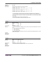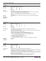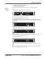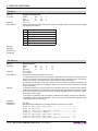
1
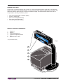
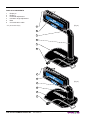
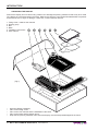
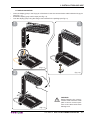
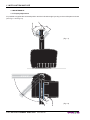
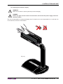
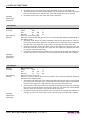
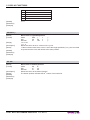
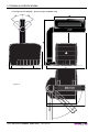
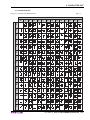
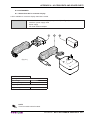
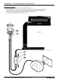
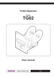
MINI
CUSTOMER
DISPLAY
XD
USER MANUAL
POS
All rights reserved. Total or partial reproduction of this manual in whatever form, whether by printed or electronic means, is forbidden. While guaranteeing that the information contained in it has been carefully checked,
CUSTOM ENGINEERING SPA and other entities utilized in the realization of this manual bear no responsibility
for how the manual is used.
Information regarding any errors found in it or suggestions on how it could be improved are appreciated. Since
products are subject to continuous check and improvement, CUSTOM ENGINEERING SPA reserves the right
to make changes in information contained in this manual without prior notification.
Copyright © 2008 CUSTOM ENGINEERING S.p.a. – Italy
CUSTOM ENGINEERING S.p.A.
Str. Berettine 2 - 43010 Fontevivo (PARMA) - Italy
Tel.: +39 0521-680111 Fax: +39 0521-610701
http: www.custom.it
Customer Service Department:
Tel.: +39 059 88 69 587
Email: [email protected]
GENERAL FEATURES
A new family of customer displays with a clear-cut, modern and elegant design enhanced by the blue backlighting of the 2-line x 20-character display. The new support system makes the display easy to position and
offers two different display heights. The XD is available in single- and double-sided versions and can be
incorporated in the body of Custom printers.
•
•
•
•
•
Nice and modern design customer display
Single or double side
Blue colour backlighted display
Easy view angle adjustment
Low and high version available
DISPLAY+ PRINTER COMPONENTS
1
2
3
4
5
6
Display 2*
Display 1
Horizontal adjustment
Inclination angle adjustment
Base
Communication cable
* Only double-side display.
(Fig.1)
1
2
3
4
6
User Manual
XD CUSTOMER DISPLAY
DISPLAY COMPONENTS
1
2
3
4
5
6
Display 2*
Display 1
Horizontal adjustment
Inclination angle adjustment
Base
Communication cable
* Only double-side display.
1
(Fig.2)
2
3
4
5
6
1
2
(Fig.3)
3
4
5
6
XD CUSTOMER DISPLAY
User Manual
TABLE OF CONTENTS
INTRODUCTION
MANUAL CONTENTS ...................................................................................................................................... 1
EXPLANATORY NOTES USED IN THIS MANUAL ......................................................................................... 1
GENERAL SAFETY INFORMATION................................................................................................................ 1
UNPACKING THE DISPLAY ............................................................................................................................ 2
1. INSTALLATION AND USE
1.1 DISPLAY MOUNTING .............................................................................................................................1-1
1.2 CONNECTIONS ......................................................................................................................................1-2
1.2.1 RS232 Serial Interface and power supply .......................................................................................1-2
1.3 SELF-TEST .............................................................................................................................................1-3
1.4 MAINTENANCE ......................................................................................................................................1-4
1.4.1 Display adjustments ........................................................................................................................1-4
1.4.2 Cleaning the customer display ........................................................................................................1-5
2. DISPLAY FUNCTIONS
2.1 COMMAND DESCRIPTIONS..................................................................................................................2-1
2.1.1 ESC/POS Emulation .......................................................................................................................2-1
2.1.2 CD5220 Emulation ........................................................................................................................2-14
3. TECHNICAL SPECIFICATIONS
3.1 TECHNICAL SPECIFICATIONS..............................................................................................................3-1
3.2 DIMENSIONS ..........................................................................................................................................3-2
3.2.1 Low version display (single / double side) .......................................................................................3-2
3.2.2 High version display (single / dopuble side) ....................................................................................3-3
3.2.3 High version display + printer (single / dopuble side) ......................................................................3-4
4. CHARACTER SET
4.1 CHARACTER SET ..................................................................................................................................4-1
APPENDIX A - ACCESSORIES AND SPARE PARTS
A.1 ACCESSORIES ..................................................................................................................................... A-1
A.1.1 Stand Alone Kit for customer display ............................................................................................. A-1
User Manual
XD CUSTOMER DISPLAY i
TABLE OF CONTENTS
Blank page
ii XD CUSTOMER DISPLAY
User Manual
INTRODUCTION
MANUAL CONTENTS
In addition to the Introduction which includes a description of the explanatory notes used in the manual, general
safety information, how to unpack the display and a brief description of the display including its basic features,
this manual is organized as follows:
Chapter 1:
Chapter 2:
Chapter 3:
Chapter 4:
Contains the information required for correct display installation and its proper use
Contains a description of the display command set
Contains Technical Specifications of the display
Contains the character sets (fonts) used by the display
EXPLANATORY NOTES USED IN THIS MANUAL
N.B.
Gives important information or suggestions relative to the use of the display.
WARNING
Information marked with this symbol must be carefully followed to guard against damaging the
display.
DANGER
Information marked with this symbol must be carefully followed to guard against operator injury
or damage.
GENERAL SAFETY INFORMATION
•
•
•
•
•
•
•
•
•
•
•
•
•
Read and keep the instructions which follow.
Follow all warnings and instructions indicated on the display.
Before cleaning the display, disconnect the power supply.
Clean the display with a damp cloth. Do not use liquid or spray products.
Do not operate the display near water.
Do not use the display on unstable surfaces that might cause it to fall and be seriously damaged.
Only use the display on hard surfaces and in environments that guarantee proper ventilation.
Make sure the display is placed in such a way as to avoid damage to its wiring.
Use the type of electrical power supply indicated on the display label. If in doubt, contact your retailer.
Do not introduce foreign objects of any kind into the display as this could cause a short circuit or damage
parts that could jeopardize display functioning.
Do not spill liquids onto the display.
Do not carry out technical operations on the display, with the exception of the scheduled maintenance
procedures specifically indicated in the user manual.
Disconnect the display from the electricity supply and have it repaired by a specialized technician when:
A.
The feed connector has been damaged.
B.
Liquid has seeped inside the display.
C.
The display has been exposed to rain or water.
D.
The display is not functioning normally despite the fact that all instructions in the users manual
have been followed.
E.
The display has been dropped and its outer casing damaged.
F.
Display performance is poor.
G.
The display is not functioning.
User Manual
XD CUSTOMER DISPLAY 1
INTRODUCTION
UNPACKING THE DISPLAY
Remove the display from its carton being careful not to damage the packing material so that it may be re-used
if the display is to be transported in the future. Make sure that all the components illustrated below are present
and that there are no signs of damage. If there are, contact Customer Service.
1. Fixing screw + washer User manual
2. Display group
3. Box
4. Base
5. Installation instructions
1
2
6 User manual
3
4
5
6
(Fig.1)
•
•
•
•
•
Open the display packaging.
Take out the fixing screw.
Take out the user manual and the installation instructions.
Take out the base and the display group.
Keep the box packing materials in the event the display must be transported/shipped in the future
2 XD CUSTOMER DISPLAY
User Manual
1. INSTALLATION AND USE
1.1 DISPLAY MOUNTING
•
•
•
Insert the display group in the hinge pin of the base. Insert the communication cable inside the hinge pin
(see Fig. 1.1).
Rotate the display group until it stops (see Fig.1.2).
Lock the display group using the fixing screw included in the package (see Fig.1.3).
3
1
(Fig.1.1)
2
(Fig.1.3)
(Fig.1.2)
User Manual
WARNING
Before fastening the communication cable check the cable
path is correct. Incorrect positions of the cable could cause
damage on it.
XD CUSTOMER DISPLAY 1-1
1. INSTALLATION AND USE
1.2 CONNECTIONS
1.2.1 RS232 Serial Interface and power supply
(Fig.1.4)
1
8
RJ45
The display with a serial RS232 interface has a female RJ45 connector. Refer to the table below for the connector pin signals:
PIN
SIGNAL
DESCRIPTION
1
TXD - OUT
Data transmission
2
RXD - IN
Data reception
3
RTS - OUT
Ready to receive data
4
CTS - IN
Ready to receive data
5
GND
Ground signal
6
GND
Ground signal
7
+VI
Power supply
8
+VI
Power supply
NOTE
The information in this page are valid for all the models.
WARNING
For the display version without printer use the power voltage indicated on the product
label.
1-2 XD CUSTOMER DISPLAY
User Manual
1. INSTALLATION AND USE
1.3 SELF-TEST
At the power ON on the display panel is indicated the current configuration (see Fig 1.5 and 1.6), the following
information is given:
(Fig.1.5)
1 Screenshot
• Firmware version.
• Baud rate.
th
2nd Screen
• Command’s set.
• Character’s set and Pass
Trough function.
(Fig.1.6)
User Manual
XD CUSTOMER DISPLAY 1-3
(Fig.1.4)
1. INSTALLATION AND USE
1.4 MAINTENANCE
1.4.1 Display adjustments
It’s possible to regulate the horizontal position and the inclination angle by acting on the mobile parts as shown
(see Fig.1.7 and Fig.1.8).
35
°
°
35
(Fig.1.7)
9
0°
(Fig.1.8)
1-4 XD CUSTOMER DISPLAY
User Manual
1. INSTALLATION AND USE
1.4.2 Cleaning the customer display
WARNING
Make sure no water or other liquids seep inside the display.
BEWARE
Before any type of work is done on the machine, disconnect the power supply cord from
the mains outlet.
The user is responsible for cleaning the display case. To clean the unit, use compressed air or a soft cloth. Do
not use alcohol, solvents or stiff brushes.
Alcohol, solvent
(Fig.1.9)
User Manual
XD CUSTOMER DISPLAY 1-5
1. INSTALLATION AND USE
Blank page
1-6 XD CUSTOMER DISPLAY
User Manual
2. DISPLAY FUNCTIONS
2.1 COMMAND DESCRIPTIONS
The table 2.1 shows the commands list, ordered by their hexadecimal value.
LEGEND :
Symbol
$
{}
n, m, t, x, y
Function
indicates the representation of the command hexadecimal value (for example $40 means HEX 40).
indicates an ASCII character not performable.
are optional parameters that can have different values.
2.1.1 ESC/POS Emulation
The following table lists all the commands for function management in ESC/POS Emulation of the display. The
commands can be transmitted to the dislpay at any moment, but they will only be carried out when the commands
ahead of them have been executed. The commands are carried out when the circular buffer is free to do so.
COMMAND DESCRIPTION TABLE
HEX Com.
ASCII Com.
(Tab.2.1)
DESCRIPTION
$08
BS
Move cursor left
$09
HT
Move cursor right
$0A
LF
Move cursor down
$0B
HOM
Move cursor to home position
$0C
CLR
Clear display screen
$0D
CR
Move cursor to left-most position
$18
CAN
Clear cursor line
$1B $25 n
ESC % n
Select/cancel user character set
$1B $26 s n m [a[p]s x ESC & s n m [a[p]s
a] (m - n+1)
x a] (m - n+1)
Define user programmables characters
$1B $3D n
ESC = n
Select peripheral device
$1B $3F n
ESC ? n
Delete user defined characters
$1B $40
ESC @
Initialize display
$1B $52 n
ESC R n
Select international characters set
$1F $01
US MD1
Specify overwrite mode
$1F $02
US MD2
Specify vertical scroll mode
$1F $03
US MD3
Specify horizontal scroll mode
$1F $0A
US LF
Move cursor up
$1F $0D
US CR
Move cursor to right-most position
$1F $24 n m
US $ n m
Move cursor to specified position
$1F $3A
US :
Set start/ end macro definition
$1F $40
US @
Execute self-test
$1F $42
US B
Move cursor to bottom position
$1F $45 n
US E n
Select/cancel blink display screen
$1F $54 h m
US T h m
Set clock display
$1F $55
US U
Display clock
$1F $58 n
US X n
Brightness adjustment
$1F $5E n m
US ^ n m
Execute macro
User Manual
XD CUSTOMER DISPLAY 2-1
2. DISPLAY FUNCTIONS
The following pages provide a more detailed description of each command.
$08
[Name]
[Format]
[Description]
[Notes]
[Default]
[Reference]
[Example]
Move cursor left.
ASCII
BS
Hex
08
Decimal
8
Moves the cursor to the left.
When the current cursor is at the left-end position, this command operates differently
depends on the display mode.
1. Overwrite mode: When the cursor reached the left-end of the lower line, it will continue
to the right-end of the upper line, overwrite previous characters. When it reached the
left end of the upper line, it will continue to the right-end of the lower line.
2. Vertical scroll mode: When the cursor reached the left-end of the lower line, the lower
line will scroll up and replace the previous upper line, the lower line will be cleared
and the cursor will continue to the right end of the lower line.
3. Horizontal scroll mode: All characters on the current line are scrolled one character to
the right. Thecursor is not moved, but the character area at the left end is cleared.
$1F $01, $1F $02, $1F $03
$09
[Name]
[Format]
[Description]
[Notes]
[Default]
[Reference]
[Example]
Move cursor right.
ASCII
HT
Hex
09
Decimal
9
Move the cursor to the right.
When the cursor reached the right-end, this command operates differently depending on
the display mode.
1. Overwrite mode: When the cursor reached the right-end of the lower line, it will continue to the left-end of the upper line, overwrite previous characters. When it reached
the right-end of the upper line, it will continue to the right-end of the lower line.
2. Vertical scroll mode: When the cursor reached the right-end of the lower line, the
lower line will scroll up to replace the upper line, the lower line is cleared and ready
to continue characters there after.
3. Horizontal scroll mode: All characters on the current line are scrolled one character to
the left. Thecursor is not moved, but the character area at the right end is cleared.
$1F $01, $1F $02, $1F $03
2-2 XD CUSTOMER DISPLAY
User Manual
2. DISPLAY FUNCTIONS
$0A
[Name]
[Format]
[Description]
[Notes]
[Default]
[Reference]
[Example]
Move cursor down.
ASCII
LF
Hex
0A
Decimal
10
Move the cursor down one line.
When the cursor reached the lower line, this command operates differently depending
on the display mode.
1. Overwrite mode: The cursor is moved to the same column on the upper line.
2. Vertical scroll mode: The characters display on the lower line are scrolled to the upper
line, and the lower line is cleared. The cursor will remain at the same position.
3. Horizontal scroll mode: The cursor will remain stationary.
$1F $01, $1F $02, $1F $03
$0B
[Name]
[Format]
[Description]
[Notes]
[Default]
[Reference]
[Example]
Move cursor to home position.
ASCII
HOM
Hex
0B
Decimal
11
The cursor will move to the left-end position of the upper line.
The start position indicates the first column of the upper line.
$0C
[Name]
[Format]
[Description]
[Notes]
[Default]
[Reference]
[Example]
Clear display screen.
ASCII
CLR
Hex
0C
Decimal
12
All the display characters will be cleared.
After execution this command the cursor moves to the home position.
$0D
[Name]
[Format]
[Description]
[Notes]
[Default]
[Reference]
[Example]
Move cursor to left-most position.
ASCII
CR
Hex
0D
Decimal
13
The cursor moves to the left-end position of the current line.
User Manual
XD CUSTOMER DISPLAY 2-3
2. DISPLAY FUNCTIONS
$18
[Name]
[Format]
[Description]
[Notes]
Clear current line.
ASCII
CAN
Hex
18
Decimal
24
The current line is cleared.
After execution this command the cursor moves to the left-end position of the current
line.
[Default]
[Reference]
[Example]
$1B $25 n
[Name]
[Format]
[Range]
[Description]
[Notes]
[Default]
[Reference]
[Example]
Select/cancel user-defined characters.
ASCII
ESC %
n
Hex
1B
25
n
Decimal
27
37
n
0≤n≤1
Selects or cancels the user-defined character set.
• When n = 1, the user-defined character set is selected. When the user-defined character
set is not defined using the $1B $26 command, the internal character set is displayed.
• When n = 0, the user-defined character set is canceled (the internal character set is
selected). In this case, this command has no effect on the user-defined characters that
have already been defined using the $1B $26 command.
• This command has no effect on the characters already displayed.
n=0
$1B $26
$1B $26 s n m [a[p]s x a] (m - n+1)
[Name]
[Format]
[Range]
[Description]
[Notes]
Defines user-defined characters.
ASCII
ESC &
s n m [a [p] s x a] m - n + 1
Hex
1B
26
s n m [a [p1 p2 ...ps] x a] m - n + 1
Decimal
27
37
s n m [a [p] s x a] m - n + 1
s=1
32 ≤ n ≤ m ≤ 126
0≤a≤5
0 ≤ p1......ps x a ≤ 255
Defines user-defined characters.
• s specifies the number of bytes in the vertical direction.
• n specifies the beginning character code for the definition, and m specifies the final
code. When a single character is defined n = m.
• The allowable character code range is from ASCII $20 (32) to $7E (126).
• a specifies the number of dots in the horizontal direction. When a< 5 any remaining dots
on the right side of the user-defined characters are padded with spaces.
• p1....pk is the dot data to be defined for the characters. This indicates the dot pattern
for a dots in the horizontal direction from the left side.
• The number of data items to be defined is s x a. When 8 bits are specified for the communication word length, the most significant bit is ignored.
• Once the user-defined characters are defined, they remain effective until they are redefined, $1B $40 is executed, or the power is turned off.
2-4 XD CUSTOMER DISPLAY
User Manual
2. DISPLAY FUNCTIONS
• When only the user-defined characters are defined and the user-defined character set
is not selected using the $1B $25 command, the user-defined characters are not displayed.
[Default]
[Reference]
[Example]
$1B $25, $1B 3F
$1B $3D n
[Name]
[Format]
[Range]
[Description]
[Notes]
[Default]
[Reference]
[Example]
Select peripheral device.
ASCII
ESC =
n
Hex
1B
3D
n
Decimal
27
61
n
1 ≤ n ≤ 2, 31 ≤ n ≤ 32
Select the device to which the host computer sends data, using n as follows:
n
FUNCTION
1, 31
Select printer
2, 32
Select display
• When n = 1 the printer is selected and all the data from the host computer is transmitted
to the printer via the display.
• When n = 2 the customer display is selected and all the data from the host computer is
processed internally in the display, and no data is transmitted to the printer.
n=2
$1B $3F n
[Name]
[Format]
[Range]
[Description]
[Notes]
[Default]
[Reference]
[Example]
Cancel user-defined characters.
ASCII
ESC ?
n
Hex
1B
3F
n
Decimal
27
63
n
32 ≤ n ≤ 126
Cancels user-defined characters.
• This command cancels the pattern defined for the character code specified by n. After the
user-defined character is cancelled, the corresponding pattern for the internal character
is printed.
• If the specified code is transmitted after, the pattern is cancelled by this command, the
internal character is displayed.
• If the specified code is not defined , this command is ignored.
• This command has no effect on character already displayed.
• If the user-defined character has not been defined for the specified character code, the
printer ignores this command.
$1B $26
User Manual
XD CUSTOMER DISPLAY 2-5
2. DISPLAY FUNCTIONS
$1B $40
[Name]
[Format]
[Description]
[Notes]
Initialize display.
ASCII
ESC @
Hex
1B
40
Decimal
27
64
Resets the various display settings to their initial values.
• The software settings are reset to their power-on values.
• This command resets the software setting to that in effect when power was turned on.
• The data in the buffer is not cleared.
• After initialize display, the display screen is cleared and move the cursor to home position.
[Default]
[Reference]
[Example]
$1B $52 n
[Name]
[Format]
[Range]
[Description]
Select an international character set.
ASCII
ESC R
n
Hex
1B
52
n
Decimal
27
82
n
0 ≤ n ≤ 10
Selects the international character set n according to the table below:
n
[Default]
[Reference]
[Example]
CHARACTER SET
0
U.S.A.
1
France
2
Germany
3
United Kingdom
4
Denmark I
5
Sweden
6
Italy
7
Spain I
8
Japan
9
Norway
10
Denmark II
n=0
$1F $01
[Name]
[Format]
[Description]
[Notes]
Select overwrite mode.
ASCII
US
MD1
Hex
1F
01
Decimal
31
1
Change the display mode to the overwrite mode.
• In this mode, entering a character code moves the cursor to the left end of the lower
line when the cursor is at the right end of the upper line, and to the left end of the upper
line when the cursor is at the right end of the lower line.
2-6 XD CUSTOMER DISPLAY
User Manual
2. DISPLAY FUNCTIONS
• This mode is selected when the power is turned on.
• Selecting overwrite mode cancels horizontal or vertical scroll mode.
• Except when the cursor is at the right end, entering a character code moves the cursor
one character to the right after displaying the character.
[Default]
[Reference]
[Example]
$1F $02, $1F $03
$1F $02
[Name]
[Format]
[Description]
[Notes]
[Default]
[Reference]
[Example]
Select vertical scroll mode.
ASCII
US
MD2
Hex
1F
02
Decimal
31
2
Change the display mode to the vertical scroll mode.
• In vertical scroll mode, entering a character code moves the cursor to the left end of
the lower line when the cursor is at the right end of the upper line, scrolls the characters
displayed on the lower line to the upper line, and clears the lower line when the cursor is
at the right end of the lower line.
At this time, the cursor is moved to the left end of the lower line.
• Selecting vertical scroll mode cancels overwrite or horizontal scroll mode.
• Except when the cursor is at the right end, entering a character code moves the cursor
one character to the right after displaying the character.
$1F $01, $1F $03
$1F $03
[Name]
[Format]
[Description]
[Notes]
[Default]
[Reference]
[Example]
Select horizontal scroll mode.
ASCII
US
MD3
Hex
1F
03
Decimal
31
3
Change the display mode to the horizontal scroll mode.
• In horizontal scroll mode, entering a character code scrolls all displayed characters (including commas and periods) one character to the left, then displays the new character
at the right end (when the cursor is at the right end of either line.)
• Selecting horizontal scroll mode cancels overwrite or vertical scroll mode.
• Except when the cursor is at the right end, entering a character code moves the cursor
one character to the right after displaying the character.
$1F $01, $1F $02
$1F $0A
[Name]
[Format]
[Description]
[Notes]
Move cursor up.
ASCII
US
LF
Hex
1F
0A
Decimal
31
10
Move the cursor up one line.
When the cursor is on the upper line, this command operates differently depending on
User Manual
XD CUSTOMER DISPLAY 2-7
2. DISPLAY FUNCTIONS
the display mode:
1. Overwrite mode: The cursor is moved to the same column on the lower line.
2. Vertical scroll mode: The characters display on the upper line are scrolled to the lower
line, and the upper line is cleared. The cursor will remain at the same position.
3. Horizontal scroll mode: The cursor is not moved.
[Default]
[Reference]
[Example]
$1F $01, $1F $02, $1F $03
$1F $0D
[Name]
[Format]
[Description]
[Notes]
[Default]
[Reference]
[Example]
Move cursor to right-most position.
ASCII
US
CR
Hex
1F
0D
Decimal
31
13
The cursor will be moved to the right-end position of the current line.
The cursor is moved only within the current window.
$1F $24 n m
[Name]
[Format]
[Range]
[Description]
[Notes]
Move cursor to specified position.
ASCII
US
$
n
m
Hex
1F
24
n
m
Decimal
31
36
n
m
1 ≤ n ≤ 20
m = 1, 2
Moves the cursor to the nth column on the mth line.
If the movement value of the cursor is out of the range specified by n or m, this command
is ignored and the cursor will remain at the same position.
[Default]
[Reference]
[Example]
$1F $3A
[Name]
[Format]
[Description]
[Notes]
Start/end macro definition.
ASCII
US
:
Hex
1F
3A
Decimal
31
58
Starts or ends macro definition.
• Up to 80 bytes can be defined for macro processing (one byte per character).
• Macro definition processing starts with the first $1F $3A command and ends with the
second $1F $3A command.
• Receipt of either of the two types of data shown below is regarded as a macro definition error. Macro definition processing is stopped, and any following data is processed
as normal data. At this time, the macro remains undefined.
1) The $1F $5E command is received during a macro processing definition.
2) A macro processing definition exceeds 80 bytes (except for the $1F $3A command).
• To delete a macro definition, send a $1F $3A command just after $1F $3A.
2-8 XD CUSTOMER DISPLAY
User Manual
2. DISPLAY FUNCTIONS
[Default]
[Reference]
[Example]
$1F $5E
Example Macro Definition Processing Program:
PRINT#1,CHR$(&H1F);CHR$(&H3A); -----------(1)
PRINT#1,CHR$(&HC); -----------------------(2)
PRINT#1,CHR$(&H1F);CHR$(&H45);CHR$(0); ---(3)
PRINT#1,”Execution MACRO !!”; ------------(4)
PRINT#1,CHR$(&H1F);CHR$(&H45);CHR$(10);---(5)
PRINT#1,CHR$(&H1F);CHR$(&H3A);------------(6)
• (1) is the starting command and (6) is the ending command of a macro definition.
• The 26-byte data from (2) to (5) is stored in the macro definition range. When the display
receives the macro execution command, the defined data is in processed order. (Refer
to $1F $5E)
• (2) is a screen clear command. (Refer to $0C)
• (3) and (5) are blinking commands. (Refer to $1F $45)
$1F $40
[Name]
[Format]
[Description]
[Notes]
Execute self-test.
ASCII
US
@
Hex
1F
40
Decimal
31
64
Executes the self-test.
• A series of self-tests is displayed. All set values except those listed below are initialized:
1. User-defined character definitions
2. Macro definitions
3. Time counter value
• After completion of the self-tests, the screen is cleared and the display position is moved
to the home position.
[Default]
[Reference]
[Example]
$1F $42
[Name]
[Format]
[Description]
[Notes]
[Default]
[Reference]
[Example]
Move cursor to bottom position.
ASCII
US
B
Hex
1F
42
Decimal
31
66
Moves the cursor to the bottom position.
• The bottom position indicates the 20th column of the lower line.
User Manual
XD CUSTOMER DISPLAY 2-9
2. DISPLAY FUNCTIONS
$1F $45 n
[Name]
[Format]
[Range]
[Description]
[Notes]
[Default]
[Reference]
[Example]
Set display screen blink interval.
ASCII
US
E
n
Hex
1F
45
n
Decimal
31
69
n
0 ≤ n ≤ 255
Sets or cancels the blink interval of the display screen.
• n specifies the blink interval. [( n 50 msec.) ON / ( n 50 msec.) OFF] is repeated.
• When n = 0, the display is kept on (cancels blinking).
• When n = 255, the display is turned off but the contents of the display are
maintained.
• This command does not affect the brightness of the vacuum fluorescent display.
n=0
$1F $54 h m
[Name]
[Format]
[Range]
[Description]
[Notes]
[Default]
[Reference]
[Example]
Set and display time counter
ASCII
US
T
h
m
Hex
1F
54
h
m
Decimal
31
84
h
m
0 ≤ h ≤ 23
0 ≤ m ≤ 59
The counter time is set and displayed at the right side of the bottom line.
• h is hours, and m is minutes.
• When this command is entered, the screen is cleared and the time is displayed in 24mode at the right side of the bottom line.
• The time counter starts from the transmitted code h:m:00.
• After the time is displayed, the cursor moves to the home position.
• The counter display disappears when any of the following occurs:
1. The cursor moves to the bottom line.
2. Display characters move to the bottom line.
3. The $0C command is received.
• Even if the time counter is cleared, it continues to be updated in the display.
h = 0, m = 0
$1F $55
$1F $55
[Name]
[Format]
[Description]
[Notes]
Display time counter.
ASCII
US
U
Hex
1F
55
Decimal
31
85
Displays the time counter at the right side of the bottom line.
• If the time has already been set using the $1F $54 (h) (m) command, the elapsed time
is displayed in real time in the format “hours : minutes : seconds”.
• If the time has not yet been set, the elapsed time (from when the counter was initialized
by turning on the power or from the $1B $40 command) is displayed in real time in the
format “hours : minutes :seconds“.
• After the counter is displayed, the cursor moves to the home position.
• The counter display is cleared when any of the following occurs:
2-10 XD CUSTOMER DISPLAY
User Manual
2. DISPLAY FUNCTIONS
1. The cursor moves to the bottom line.
2. Display characters move to the bottom line.
3. The $0C command is received.
• Even if the time counter is cleared, it continues to be updated in the display.
[Default]
[Reference]
[Example]
$1F $54
1. Counter display just before receiving $1F $54 (h) (m):
2. Example Display Before Setting the Counter
$1F $54 h m $1F $54 $0E $0F (31) (84) (14) (15)
The screen is cleared, and the input time is displayed at the right side of the lower line;
counting begins from 14:15:00 seconds. At this time, the cursor moves to the home position indicated by “_”.
3. Display data (“ABC”) is received:
Example Indication When the Cursor Does Not Move counter display in the bottom line
has no effect on data displayed in the top line.
4. $0A $10 (16) if received:
Moving the cursor to the bottom line clears the time display, but counting continues internally.
Note: In this example the cursor is represented on its position for a more clear explanation but is not enabled with $1F$54 command.
User Manual
XD CUSTOMER DISPLAY 2-11
2. DISPLAY FUNCTIONS
$1F $58 n
[Name]
[Format]
[Range]
[Description]
[Notes]
[Default]
[Reference]
[Example]
Brightness adjustment.
ASCII
US
X
n
Hex
1F
58
n
Decimal
31
88
n
1≤n≤6
Sets the brightness of the fluorescent character display tube. n selects the percentage
of brightness as follows:
n
BRIGHTNESS
1
20%
2
40%
3
60%
4
100%
5
Negative fading
6
Positive fading
n=4
$1F $5E n m
[Name]
[Format]
[Range]
[Description]
[Notes]
[Default]
[Reference]
[Example]
Execute macro.
ASCII
US
^
n
m
Hex
1F
5E
n
m
Decimal
31
94
n
m
0 ≤ n ≤ 255
0 ≤ m ≤ 255
Executes the process defined as a macro.
• n specifies the time interval for displaying characters in units of [n x 20 msec] when a
macro is executed. This specifies the time interval before displaying each successive
character but does not affect the processing speed of command codes.
• m specifies the interval of execution. Where macro processing is repeated, it starts over
from the beginning after the completion state of the previous macro processing is held
for [m x 50 msec].
• If data is received from the host during macro processing, the macro processing is terminated.
• After macro processing is finished, the current window is cleared and the cursor is moved
to the home position in the current window. Display settings at the completion of macro
processing remain valid.
• If a macro is undefined, this command is invalid and the display content is not affected.
• If $1B $40, and $1F $40 are defined in the macro, these commands are ignored when
executing the macro commands.
$1F $3A
Example Macro Definition Processing and Macro Execution Program:
PRINT #1,CHR$(&H1F);CHR$(&H3A);--------------------(1)
PRINT #1,CHR$(&HC);--------------------------------(1)
PRINT #1,CHR$(&H1F);CHR$(&H45);CHR$(0);------------(1)
PRINT #1,” Execution MACRO !!”;--------------------(1)
PRINT #1,CHR$(&H1F);CHR$(&H45);CHR$(10);-----------(1)
PRINT #1,CHR$(&H1F);CHR$(&H3A);--------------------(1)
PRINT #1,CHR$(&H1F);CHR$(&H5E);CHR$(5);CHR$(100);--(2)
2-12 XD CUSTOMER DISPLAY
User Manual
2. DISPLAY FUNCTIONS
• (1) Macro definition
• (2) Macro execution is started.In this case, the time interval for displaying the characters
is (5 x 20 msec). When 100 msec has passed after the character “E” has been displayed,
the next character, “x”, is displayed.
after 100 msec
The macro execution interval is (100 x 50 msec). After the blinking display shown in the
figure below is held for 5 seconds, macro processing is repeated from a clear screen.
User Manual
XD CUSTOMER DISPLAY 2-13
2. DISPLAY FUNCTIONS
2.1.2 CD5220 Emulation
The following table lists all the commands for function management in CD5220 display Emulation. The commands can be transmitted any moment, but they will only be carried out when the commands ahead of them
have been executed. The commands are carried out when the circular buffer is free to do so.
(Tab.2.2)
COMMAND DESCRIPTION TABLE
HEX Com.
ASCII Com.
DESCRIPTION
$08
BS
Move cursor left
$09
HT
Move cursor right
$0A
LF
Move cursor down
$0B
HOM
Move cursor to home position
$0C
CLR
Clear display screen
$0D
CR
Move cursor to left-most position
$18
CAN
Clear cursor line
$1B $11
ESC DC1
Specify overwrite mode
$1B $12
ESC DC2
Specify vertical scroll mode
$1B $13
ESC DC3
Specify horizontal scroll mode
$1B $25 n
ESC % n
Select/cancel user character set
$1B $26 s n m [a[p]s x a]
(m - n+1)
ESC & s n m [a[p]s x a]
(m - n+1)
Define user programmables characters
$1B $2A n
ESC * n
Brightness adjustment
$1B $3D n
ESC = n
Select peripheral device
$1B $3F n
ESC ? n
Delete user defined characters
$1B $40
ESC @
Initialize display
$1B $51 $41 n x 20 $0D
ESC Q A ....CR
Set the string display mode, write string to upper line
$1B $51 $42 n x 20 $0D
ESC Q B ....CR
Set the string display mode, write string to lower line
$1B $51 $44 n x m $0D
ESC Q D ....CR
Upper line message scroll continuously
$1B $5B 41
ESC [ A
Move cursor up
$1B $5B 42
ESC [ B
Move cursor down
$1B $5B 43
ESC [ C
Move cursor right
$1B $5B 44
ESC [ D
Move cursor left
$1B $5B 48
ESC [ H
Move cursor to home position
$1B $5B 4B
ESC [ K
Move cursor to bottom position
$1B $5B 4C
ESC [ L
Move cursor to left-most position
$1B $5B 52
ESC [ R
Move cursor to right-most position
$1B $66 n
ESC f n
Select international characters set
$1B $6C x y
US l x y
Move cursor to specified position.
$1F $42
US B
Move cursor to bottom position.
Given below are more detailed descriptions of each command.
2-14 XD CUSTOMER DISPLAY
User Manual
2. DISPLAY FUNCTIONS
$08
[Name]
[Format]
[Description]
[Notes]
[Default]
[Reference]
[Example]
Move cursor left.
ASCII
BS
Hex
08
Decimal
8
Moves the cursor to the left.
When the current cursor is at the left-end position, this command operates differently
depends on the display mode.
1. Overwrite mode: When the cursor reached the left-end of the lower line, it will continue
to the right-end of the upper line, overwrite previous characters. When it reached the
left end of the upper line, it will continue to the right-end of the lower line.
2. Vertical scroll mode: When the cursor reached the left-end of the lower line, the lower
line will scroll up and replace the previous upper line, the lower line will be cleared
and the cursor will continue to the right end of the lower line.
3. Horizontal scroll mode: All characters on the current line are scrolled one character to
the right. Thecursor is not moved, but the character area at the left end is cleared.
$1B $11, $1B $12, $1B $13
$09
[Name]
[Format]
[Description]
[Notes]
[Default]
[Reference]
[Example]
Move cursor right.
ASCII
HT
Hex
09
Decimal
9
Move the cursor to the right.
When the cursor reached the right-end, this command operates differently
depending on the display mode.
1. Overwrite mode: When the cursor reached the right-end of the lower line, it will continue to the left-end of the upper line, overwrite previous characters. When it reached
the right-end of the upper line, it will continue to the right-end of the lower line.
2. Vertical scroll mode: When the cursor reached the right-end of the lower line, the
lower line will scroll up to replace the upper line, the lower line is cleared and ready
to continue characters there after.
3. Horizontal scroll mode: All characters on the current line are scrolled one character to
the left. Thecursor is not moved, but the character area at the right end is cleared.
$1B $11, $1B $12, $1B $13
User Manual
XD CUSTOMER DISPLAY 2-15
2. DISPLAY FUNCTIONS
$0A
[Name]
[Format]
[Description]
[Notes]
[Default]
[Reference]
[Example]
Move cursor down.
ASCII
LF
Hex
0A
Decimal
10
Move the cursor down one line.
When the cursor reached the lower line, this command operates
differently depending on the display mode.
1. Overwrite mode: The cursor is moved to the same column on the upper line.
2. Vertical scroll mode: The characters display on the lower line are scrolled to the upper
line, and the lower line is cleared. The cursor will remain at the same position.
3. Horizontal scroll mode: The cursor will remain stationary.
$1B $11, $1B $12, $1B $13
$0B
[Name]
[Format]
[Description]
[Notes]
[Default]
[Reference]
[Example]
Move cursor to home position.
ASCII
HOM
Hex
0B
Decimal
11
The cursor will move to the left-end position of the upper line.
The start position indicates the first column of the upper line.
$0C
[Name]
[Format]
[Description]
[Notes]
[Default]
[Reference]
[Example]
Clear display screen.
ASCII
CLR
Hex
0C
Decimal
12
All the display characters will be cleared.
After execution this command the cursor moves to the home posiition.
$0D
[Name]
[Format]
[Description]
[Notes]
[Default]
[Reference]
[Example]
Move cursor to left-most position.
ASCII
CR
Hex
0D
Decimal
13
The cursor moves to the left-end position of the current line.
2-16 XD CUSTOMER DISPLAY
User Manual
2. DISPLAY FUNCTIONS
$18
[Name]
[Format]
[Description]
[Notes]
Clear current line.
ASCII
CAN
Hex
18
Decimal
24
The current line is cleared.
After execution this command the cursor moves to the left-end position of the current
line.
[Default]
[Reference]
[Example]
$1B $11
[Name]
[Format]
[Description]
[Notes]
[Default]
[Reference]
[Example]
Select overwrite mode.
ASCII
ESC DC1
Hex
1B
11
Decimal
27
17
Change the display mode to the overwrite mode.
• In this mode, entering a character code moves the cursor to the left end of the lower
line when the cursor is at the right end of the upper line, and to the left end of the upper
line when the cursor is at the right end of the lower line.
• This mode is selected when the power is turned on.
• Selecting overwrite mode cancels horizontal or vertical scroll mode.
• Except when the cursor is at the right end, entering a character code moves the cursor
one character to the right after displaying the character.
$1B $12, $1B $13
$1B $12
[Name]
[Format]
[Description]
[Notes]
[Default]
[Reference]
[Example]
Select vertical scroll mode.
ASCII
ESC DC2
Hex
1B
12
Decimal
27
18
Change the display mode to the vertical scroll mode.
• In vertical scroll mode, entering a character code moves the cursor to the left end of
the lower line when the cursor is at the right end of the upper line, scrolls the characters
displayed on the lower line to the upper line, and clears the lower line when the cursor is
at the right end of the lower line.
At this time, the cursor is moved to the left end of the lower line.
• Selecting vertical scroll mode cancels overwrite or horizontal scroll mode.
• Except when the cursor is at the right end, entering a character code moves the cursor
one character to the right after displaying the character.
$1B $11, $1B $13
User Manual
XD CUSTOMER DISPLAY 2-17
2. DISPLAY FUNCTIONS
$1B $13
[Name]
[Format]
[Description]
[Notes]
[Default]
[Reference]
[Example]
Select horizontal scroll mode.
ASCII
ESC DC3
Hex
1B
13
Decimal
27
19
Change the display mode to the horizontal scroll mode.
• In horizontal scroll mode, entering a character code scrolls all displayed characters (including commas and periods) one character to the left, then displays the new character
at the right end (when the cursor is at the right end of either line.)
• Selecting horizontal scroll mode cancels overwrite or vertical scroll mode.
• Except when the cursor is at the right end, entering a character code moves the cursor
one character to the right after displaying the character.
$1B $11, $1B $12
$1B $25 n
[Name]
[Format]
[Range]
[Description]
[Notes]
[Default]
[Reference]
[Example]
Select/cancel user-defined characters.
ASCII
ESC %
n
Hex
1B
25
n
Decimal
27
37
n
0≤n≤1
Selects or cancels the user-defined character set.
• When n = 1, the user-defined character set is selected. When the user-defined character
set is not defined using the $1B $26 command, the internal character set is displayed.
• When n = 0, the user-defined character set is canceled (the internal character set is
selected). In this case, this command has no effect on the user-defined characters that
have already been defined using the $1B $26 command.
• This command has no effect on the characters already displayed.
n=0
$1B $26
$1B $26 s n m [a [p] s x a]
[Name]
[Format]
[Range]
[Description]
Defines user-defined characters.
ASCII
ESC &
s n m [a [p] s x a] m - n + 1
Hex
1B
26
n m [a [p1 p2 ...ps] x a] m - n + 1
Decimal
27
37
s n m [a [p] s x a] m - n + 1
s=1
32 ≤ n ≤ m ≤ 126
0≤a≤5
0 ≤ p1......ps x a ≤ 255
Defines user-defined characters.
s specifies the number of bytes in the vertical direction.
n specifies the beginning character code for the definition, and m specifies the final code.
When a single character is defined n = m.
• The allowable character code range is from ASCII $20 (32) to $7E (126).
• a specifies the number of dots in the horizontal direction. When a< 5 any remaining
dots on the right side of the user-defined characters are padded with spaces.
• p1....pk is the dot data to be defined for the characters. This indicates the dot pattern
for a dots in the horizontal direction from the left side.
2-18 XD CUSTOMER DISPLAY
User Manual
2. DISPLAY FUNCTIONS
[Notes]
[Default]
[Reference]
[Example]
• The number of data items to be defined is s x a. When 8 bits are specified for the communication word length, the most significant bit is ignored.
• Once the user-defined characters are defined, they remain effective until they are redefined, $1B $40 is executed, or the power is turned off.
• When only the user-defined characters are defined and the user-defined character set
is not selected using the $1B $25 command, the user-defined characters are not displayed.
$1B $25, $1B $3F
$1B $2A n
[Name]
[Format]
[Range]
[Description]
[Notes]
[Default]
[Reference]
[Example]
Brightness adjustment.
ASCII
ESC *
n
Hex
1B
2A
n
Decimal
27
42
n
1≤n≤6
Sets the brightness of the fluorescent character display tube. n selects the percentage
of brightness as follows:
n
BRIGHTNESS
1
20%
2
40%
3
60%
4
100%
5
Negative fading
6
Positive fading
n=4
$1B $3D n
[Name]
[Format]
[Range]
[Description]
[Notes]
Select peripheral device.
ASCII
ESC =
n
Hex
1B
3D
n
Decimal
27
61
n
1 ≤ n ≤ 2, 31 ≤ n ≤ 32
Select the device to which the host computer sends data, using n as follows:
n
FUNCTION
1, 31
Select printer
2, 32
Select display
• When n = 1 the printer is selected and all the data from the host computer is transmitted
to the printer via the display.
• When n = 2 the customer display is selected and all the data from the host computer is
processed internally in the display, and no data is transmitted to the printer.
User Manual
XD CUSTOMER DISPLAY 2-19
2. DISPLAY FUNCTIONS
[Default]
[Reference]
[Example]
n=2
$1B $3F n
[Name]
[Format]
[Range]
[Description]
[Notes]
[Default]
[Reference]
[Example]
Cancel user-defined characters.
ASCII
ESC ?
n
Hex
1B
3F
n
Decimal
27
63
n
32 ≤ n ≤ 126
Cancels user-defined characters.
• This command cancels the pattern defined for the character code specified by n. After the
user-defined character is cancelled, the corresponding pattern for the internal character
is printed.
• If the specified code is transmitted after, the pattern is cancelled by this command, the
internal character is displayed.
• If the specified code is not defined , this command is ignored.
• This command has no effect on character already displayed.
• If the user-defined character has not been defined for the specified character code, the
printer ignores this command.
$1B $26
$1B $40
[Name]
[Format]
[Description]
[Notes]
[Default]
[Reference]
[Example]
Initialize display.
ASCII
ESC @
Hex
1B
40
Decimal
27
64
Resets the various display settings to their initial values.
• The software settings are reset to their power-on values.
$1B $51 $41 n x 20 $0D
[Name]
[Format]
[Description]
[Notes]
[Default]
[Reference]
[Example]
Set the string display mode, and write string to display
ASCII
ESC Q
A
(n) x 20
CR
Hex
1B
51
41
(n) x 20
0D
Decimal
27
81
65
(n) x 20
13
Set the string display mode, write to upper line.
2-20 XD CUSTOMER DISPLAY
User Manual
2. DISPLAY FUNCTIONS
$1B $51 $42 n x 20 $0D
[Name]
[Format]
[Description]
[Notes]
[Default]
[Reference]
[Example]
Set the string display mode, and write string to display.
ASCII
ESC Q
B
(n) x 20
CR
Hex
1B
51
42
(n) x 20
0D
Decimal
27
81
66
(n) x 20
13
Set the string display mode, write to lower line.
$1B $51 $44 n x 20 $0D
[Name]
[Format]
[Description]
Upper line message scroll continuously
ASCII
ESC Q
D
(n) x 20
CR
Hex
1B
51
44
(n) x 20
0D
Decimal
27
81
68
(n) x 20
13
The message (previously defined) will scroll continuously in the horizontal direction until
a new command is received.
[Notes]
[Default]
[Reference]
[Example]
$1B $5B $41
[Name]
[Format]
[Description]
[Notes]
Move cursor up.
ASCII
ESC [
A
Hex
1B
5B
41
Decimal
27
91
65
Move the cursor up one line.
When the cursor is on the upper line, this command operates differently depending on
the display mode :
1. Overwrite mode: The cursor is moved to the same column on the lower line.
2. Vertical scroll mode: The characters display on the upper line are scrolled to the lower
line, and the upper line is cleared. The cursor will remain at the same position.
3. Horizontal scroll mode: The cursor is not moved.
[Default]
[Reference]
[Example]
$1B $5B $42
[Name]
[Format]
[Description]
[Notes]
Move cursor down.
ASCII
ESC [
B
Hex
1B
5B
42
Decimal
27
91
66
Move the cursor down one line.
When the cursor reached the lower line, this command operates
differently depending on the display mode.
User Manual
XD CUSTOMER DISPLAY 2-21
2. DISPLAY FUNCTIONS
1. Overwrite mode: The cursor is moved to the same column on the upper line.
2. Vertical scroll mode: The characters display on the lower line are scrolled to the upper
line, and the lower line is cleared. The cursor will remain at the same position.
3. Horizontal scroll mode: The cursor will remain stationary.
[Default]
[Reference]
[Example]
$1B $5B $43
[Name]
[Format]
[Description]
[Notes]
Move cursor right.
ASCII
ESC [
C
Hex
1B
5B
43
Decimal
27
91
67
Move the cursor to the right.
When the cursor reached the right-end, this command operates differently depending on
the display mode.
1. Overwrite mode: When the cursor reached the right-end of the lower line, it will continue to the left-end of the upper line, overwrite previous characters. When it reached
the right-end of the upper line, it will continue to the right-end of the lower line.
2. Vertical scroll mode: When the cursor reached the right-end of the lower line, the
lower line will scroll up to replace the upper line, the lower line is cleared and ready
to continue characters there after.
3. Horizontal scroll mode: All characters on the current line are scrolled one character to
the left. Thecursor is not moved, but the character area at the right end is cleared.
[Default]
[Reference]
[Example]
$1B $5B $44
[Name]
[Format]
[Description]
[Notes]
Move cursor left.
ASCII
ESC [
D
Hex
1B
5B
44
Decimal
27
91
68
Moves the cursor to the left.
When the current cursor is at the left-end position, this command operates differently
depends on the display mode.
1. Overwrite mode: When the cursor reached the left-end of the lower line, it will continue
to the right-end of the upper line, overwrite previous characters. When it reached the
left end of the upper line, it will continue to the right-end of the lower line.
2. Vertical scroll mode: When the cursor reached the left-end of the lower line, the lower
line will scroll up and replace the previous upper line, the lower line will be cleared
and the cursor will continue to the right end of the lower line.
3. Horizontal scroll mode: All characters on the current line are scrolled one character to
the right. Thecursor is not moved, but the character area at the left end is cleared.
[Default]
[Reference]
[Example]
2-22 XD CUSTOMER DISPLAY
User Manual
2. DISPLAY FUNCTIONS
$1B $5B $48
[Name]
[Format]
[Description]
[Notes]
[Default]
[Reference]
[Example]
Move cursor to home position.
ASCII
ESC [
H
Hex
1B
5B
48
Decimal
27
91
72
The cursor will move to the left-end position of the upper line.
The start position indicates the first column of the upper line.
$1B $5B $4C
[Name]
[Format]
[Description]
[Notes]
[Default]
[Reference]
[Example]
Move cursor to left-most position.
ASCII
ESC [
L
Hex
1B
5B
4C
Decimal
27
91
76
The cursor moves to the left-end position of the current line.
$1B $5B $52
[Name]
[Format]
[Description]
[Notes]
[Default]
[Reference]
[Example]
Move cursor to right-most position.
ASCII
ESC [
R
Hex
1B
5B
52
Decimal
27
91
82
The cursor will be moved to the right-end position of the current line.
The cursor is moved only within the current window.
$1B $66 n
[Name]
[Format]
[Range]
[Description]
Select an international character set.
ASCII
ESC f
n
Hex
1B
66
n
Decimal
27
102
n
0 ≤ n ≤ 10
Selects the international character set n according to the table below:
n
CHARACTER SET
0
U.S.A.
1
France
2
Germany
3
United Kingdom
4
Denmark I
5
Sweden
User Manual
XD CUSTOMER DISPLAY 2-23
2. DISPLAY FUNCTIONS
[Default]
[Reference]
[Example]
6
Italy
7
Spain I
8
Japan
9
Norway
10
Denmark II
n=0
$1B $6C x y
[Name]
[Format]
[Range]
[Description]
[Notes]
Move cursor to specified position.
ASCII
ESC |
x
y
Hex
1B
6C
x
y
Decimal
27
108
x
y
1 ≤ x ≤ 20
y = 1, 2
Moves the cursor to the xth column on the yth line.
• If the movement value of the cursor is out of the range specified by x or y, this command
is ignored and the cursor will remain at the same position.
[Default]
[Reference]
[Example]
$1F $42
[Name]
[Format]
[Description]
[Notes]
[Default]
[Reference]
[Example]
Move cursor to bottom position.
ASCII
US
B
Hex
1F
42
Decimal
31
66
Moves the cursor to the bottom position.
The bottom position indicates the 20th column of the lower line.
2-24 XD CUSTOMER DISPLAY
User Manual
3. TECHNICAL SPECIFICATIONS
3.1 TECHNICAL SPECIFICATIONS
Table 3.1 gives the main technical specifications for the display.
Serial RS232
Available interface
Baud rate
(Tab.3.1)
From 600 to 38400 bps
ESC/POS, CD5220
Emulations
68509 hours
MTBF
DISPLAY SPECIFICATIONS
Display method
Number of characters
Liquid crystal display backlighted
40 (20 columns x 2 lines)
Backlighted colour
Blue
MECHANICAL SPECIFICATION
View angle
8 ÷ 35 °
Rotation angle
90° (1 direction)
Inclination angle
-35° ÷ +35°
CHARACTER SPECIFICATIONS
Character type
Alphanumeric = 96
International characters set = 12
Character font
5 x 8 dot matrix
Character size (L x H)
6 mm x 9.66 mm
Character pitch
7.2 mm x 10.98 mm
Spacing between character
1.2 mm
Spacing between lines
1.32 mm
ELECTRICAL SPECIFICATIONS
Power supply
12 ÷ 24 Vdc ± 10%
Peak current
2 A peak
Normal absorption
150 mA (single side)
200 mA (double side)
COMPLIANCE STANDARD
Electric safety
2006/95/CE - Low voltage directive
EN60950
2004/108/CE - EMC Compatibility directive
Electromagnetic compatibility
EN55024
EN55022 class B
Climatic test
IEC 68-2
EMVIROMENTAL CONDITIONS
Operating temperature
0 ÷ 50°C
Relative humidity
Storage temperature / Humidity
10 ÷ 80% Rh
-20 ÷ 70 °C / 10% ÷ 90% Rh
User Manual
XD CUSTOMER DISPLAY 3-1
3. TECHNICAL SPECIFICATIONS
3.2 DIMENSIONS
3.2.1 Low version display (single / double side)
35
°
202
77
192
°
35
145
257
(Fig.3.1)
198
9
0°
257
3-2 XD CUSTOMER DISPLAY
User Manual
3. TECHNICAL SPECIFICATIONS
3.2.2 High version display (single / dopuble side)
35
°
202
206
321
°
35
145
257
(Fig.3.2)
198
9
0°
257
User Manual
XD CUSTOMER DISPLAY 3-3
3. TECHNICAL SPECIFICATIONS
3.2.3 High version display + printer (single / dopuble side)
35
°
202
321
78
°
35
10
145
50
257
(Fig.3.3)
198
9
0°
257
3-4 XD CUSTOMER DISPLAY
User Manual
4. CHARACTER SET
4.1 CHARACTER SET
In Fig.4.1 is shown the characters set.
Fig.4.1
UPPER 4 BIT
2
3
4
5
6
7
8
9
A
B
C
D
E
F
0
1
2
3
4
5
LOWER 4 BIT
6
7
8
9
A
B
C
D
E
F
User Manual
XD CUSTOMER DISPLAY 4-1
4. CHARACTER SET
Blank page
4-2 XD CUSTOMER DISPLAY
User Manual
APPENDIX A - ACCESSORIES AND SPARE PARTS
A.1 ACCESSORIES
A.1.1 Stand Alone Kit for customer display
A kit is available for customer display stand alone model.
PCXSP-CDKUBE
Stand Alone Kit for customer display composed of (See Fig. A.1) :
1. Interface / power supply cable
2. Power supply
3. F/F RJ45 Ethernet adapter
1
2
3
(Fig.A.1)
POWER SUPPLY 230Vac
Input specifications
Input voltage
Input frequency
230 Vac
50 Hz
Output specifications
Output voltage
18 Vdc
NOTE
This kit is usable with all models.
User Manual
XD CUSTOMER DISPLAY A-1
APPENDIX A - ACCESSORIES AND SPARE PARTS
Assembly instruction
To connect the kit refer to Fig.A.2 and proceeds as follow:
• Connect the RJ45 connector from the customer display (4) with the ethernet adapter (3).
• Connect the RJ45 connector from interface cable (1A) with the ethernet adapter (3).
• Connect the power supply jack (2) with the interface cable (1B).
• Insert the power supply plug in the wall socket.
RS232
1B
(Fig.A.2)
2
4
3
1A
A-2 XD CUSTOMER DISPLAY
User Manual
Rev. 1.00
Part Number : DOME-XD
CUSTOM ENGINEERING SPA
World Headquarters
Via Berettine, 2 - 43100 Fontevivo
Tel. +39 0521 680111 - Fax +39 0521 610701
[email protected] - www.custom.biz
All rigths reserved
www.custom.biz