1
User Manual
Handheld Pressure Calibrator
JOFRA HPC600
©Copyright 2010 AMETEK Denmark A/S
...because calibration is
a matter of confidence
JOFRA HPC600
Reference Manual
1. Introduction . . . . . . . . . . . . . . . . . . . . . . . . . . . . . . . . . . . . . . . . . . . . . . . . . . .1
1.1 Contacting AMETEK/JOFRA . . . . . . . . . . . . . . . . . . . . . . . . . . . . . . . . . . . . . . . .1
1.2 Standard Equipment . . . . . . . . . . . . . . . . . . . . . . . . . . . . . . . . . . . . . . . . . . . . . .1
1.3 Safety Information . . . . . . . . . . . . . . . . . . . . . . . . . . . . . . . . . . . . . . . . . . . . . . . .1
2. Calibrator Interface . . . . . . . . . . . . . . . . . . . . . . . . . . . . . . . . . . . . . . . . . . . .4
2.1 Calibrator Display . . . . . . . . . . . . . . . . . . . . . . . . . . . . . . . . . . . . . . . . . . . . . . . .6
2.2 Using the Backlight . . . . . . . . . . . . . . . . . . . . . . . . . . . . . . . . . . . . . . . . . . . . . . .8
2.3 Using the Zero Function . . . . . . . . . . . . . . . . . . . . . . . . . . . . . . . . . . . . . . . . . . .8
2.4 Other Menu Controlled Functions . . . . . . . . . . . . . . . . . . . . . . . . . . . . . . . . . . . .9
3. Initial Setup and Basic Pressure Generation . . . . . . . . . . . . . . . . . . . . . . . .19
3.1 Electric Pump Considerations . . . . . . . . . . . . . . . . . . . . . . . . . . . . . . . . . . . . . .20
4. Measuring Pressure . . . . . . . . . . . . . . . . . . . . . . . . . . . . . . . . . . . . . . . . . . .21
4.1 Media Compatibility . . . . . . . . . . . . . . . . . . . . . . . . . . . . . . . . . . . . . . . . . . . . .21
4.2 Measuring Pressure with External Modules . . . . . . . . . . . . . . . . . . . . . . . . . . .21
5. Measuring and Generating Current
6. Measuring Voltage
. . . . . . . . . . . . . . . . . . . . . . . . . . . . . . .22
. . . . . . . . . . . . . . . . . . . . . . . . . . . . . . . . . . . . . . . . . . . .24
7. Measuring Temperature with an RTD . . . . . . . . . . . . . . . . . . . . . . . . . . . . . .24
8. Performing a Pressure Switch Test
. . . . . . . . . . . . . . . . . . . . . . . . . . . . . . .25
9. Calibrating Transmitters
. . . . . . . . . . . . . . . . . . . . . . . . . . . . . . . . . . . . . . .28
9.1 Using the mA Input Function . . . . . . . . . . . . . . . . . . . . . . . . . . . . . . . . . . . . . . .28
9.2 Calibrating a Pressure-to-Current Transmitter . . . . . . . . . . . . . . . . . . . . . . . . . .28
9.3 Percent Error Function . . . . . . . . . . . . . . . . . . . . . . . . . . . . . . . . . . . . . . . . . . .29
10. Minimum and Maximum Storage Capability . . . . . . . . . . . . . . . . . . . . . . . .32
11. Leak Test . . . . . . . . . . . . . . . . . . . . . . . . . . . . . . . . . . . . . . . . . . . . . . . . . . . .32
12. Factory Setups
. . . . . . . . . . . . . . . . . . . . . . . . . . . . . . . . . . . . . . . . . . . . . .34
13. Custody Transfer / Flow Calibration . . . . . . . . . . . . . . . . . . . . . . . . . . . . . .36
14. Remote Operation . . . . . . . . . . . . . . . . . . . . . . . . . . . . . . . . . . . . . . . . . . . .36
15. Specifications
. . . . . . . . . . . . . . . . . . . . . . . . . . . . . . . . . . . . . . . . . . . . . . .37
16. Maintenance . . . . . . . . . . . . . . . . . . . . . . . . . . . . . . . . . . . . . . . . . . . . . . . .38
16.1 Replacing Batteries . . . . . . . . . . . . . . . . . . . . . . . . . . . . . . . . . . . . . . . . . . . . .38
16.2 Cleaning the Unit . . . . . . . . . . . . . . . . . . . . . . . . . . . . . . . . . . . . . . . . . . . . . .38
16.3 Valve Cleaning Procedure . . . . . . . . . . . . . . . . . . . . . . . . . . . . . . . . . . . . . . . .38
16.4 Service Center Calibration or Repair . . . . . . . . . . . . . . . . . . . . . . . . . . . . . . .39
1. Introduction
JOFRA HPC600 combines 5 units into a single portable calibrator. HPC600
contains; pressure indicator, calibration pump, mA loop tester
(measure/source), voltmeter and finally a high accuracy thermometer.
The JOFRA HPC600 is designed to be a simple to use yet very versatile
pressure calibrator. Its internal pressure sensor combined with an innovative
electrically powered pump along with inputs for mA, voltage, switch contacts
and an RTD probe allow the HPC600 to calibrate virtually any pressure
device. An external pressure module option allows an even wider range of
pressure calibration options including absolute and differential.
1.1 Contacting AMETEK/JOFRA
US, Canada, Latin America
Europe, Africa, Middle East
Asia
AMETEK M&CT 1-800-527-9999
AMETEK Denmark A/S + 45 4816 8000
AMETEK Singapore Pte. Ltd.
At + 65 (64) 842 388
1.2 Standard Equipment
Check to see if your calibrator is complete. It should include: JOFRA
HPC600 Calibrator, instruction manual, test leads, calibration hose kit with
fittings, carrying case, calibration certificate with data.
1.3 Safety information
Symbols Used
The following table lists the International Electrical Symbols. Some or all of
these symbols may be used on the instrument or in this manual.
Symbol
Description
AC (Alternating Current)
AC-DC
Battery
CE Complies with European Union Directives
DC
1
Symbol
Description
Double Insulated
Electric Shock
Fuse
PE Ground
Hot Surface (Burn Hazard)
Read the User’s Manual (Important Information)
Off
On
Canadian Standards Association
The following definitions apply to the terms “Warning” and “Caution”.
• “Warning” identifies conditions and actions that may pose hazards to the
user.
• “Caution” identifies conditions and actions that may damage the instrument
being used.
Use the calibrator only as specified in this manual, otherwise injury and
damage to the calibrator may occur.
Warning
To avoid possible electric shock or personal injury:
• Do not apply more than the rated voltage. See specifications for
supported ranges.
• Follow all equipment safety procedures.
• Never touch the probe to a voltage source when the test leads are
plugged into the current terminals.
• Do not use the calibrator if it is damaged. Before you use the calibrator,
inspect the case. Look for cracks or missing plastic. Pay particular
attention to the insulation surrounding the connectors.
• Select the proper function and range for your measurement.
2
• Make sure the battery cover is closed and latched before you operate the
calibrator.
• Remove test leads from the calibrator before you open the battery door.
• Inspect the test leads for damaged insulation or exposed metal. Check
test leads continuity. Replace damaged test leads before you use the
calibrator.
• When using the probes, keep your fingers away from the probe contacts.
Keep your fingers behind the finger guards on the probes.
• Connect the common test lead before you connect the live test lead.
When you disconnect test leads, disconnect the live test lead first.
• Do not use the calibrator if it operates abnormally. Protection may be
impaired. When in doubt, have the calibrator serviced.
• Do not operate the calibrator around explosive gas, vapor, or dust.
• When measuring pressure, make sure the process pressure line is shut off
and depressurized before you connect it or disconnect it from the
pressure module.
• Disconnect test leads before changing to another measure or source
function.
• When servicing the calibrator, use only specified replacement parts.
• To avoid false readings, which could lead to possible electric shock or
personal injury, replace the battery as soon as the battery indicator
appears.
Caution
To avoid possible damage to calibrator or to equipment under test:
• Use the proper jacks, function, and range for your measurement or sourcing
application.
3
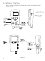
2. Calibrator Interface
Figure 1 shows the location of the pressure controls, connection port and
electrical inputs.
4
Figure 1
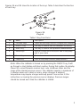
Figures 2A and 2B show the location of the keys. Table 2 describes the function
of each key.
Figure 2A
Keypad
Table 2 Key Functions
No.
Name
Description
1
Function Keys
These are soft keys used to configure the calibrator
2
ON/OFF Key
This key is used to turn the calibrator on and off
3
ZERO Key
This key is used to zero pressure measurements
4
Arrow Keys
Used to control mA source/sim. and to set pump
and % error limits
5
Home Key
Return to main menu screen
6
Pump Key
Push to run pump (Electric pump version)
Note: When the calibrator is turned on by pressing the ON/OFF key, it will
go through a short startup self-check routine. During that routine, the display
shows the current firmware revision level, auto shutdown status and the
range of the internal pressure sensor. The calibrator requires a maximum of
5 minutes warm-up to rated accuracy. Large changes in ambient
temperature may require a longer warm-up period. See section 2.3 for
instructions on zeroing the pressure sensor displays. Pressure ranges
should be zeroed each time the calibrator is started.
5
2.1 Calibrator Display
The Calibrator Display consists of two regions: The menu bar (located along
the bottom of the screen) is used to access a menu system. The main
display (the rest) consists of up to three process measurement sub-regions.
These sub-regions will henceforth be referred to as the UPPER, MIDDLE
and LOWER displays. Figure 3 shows the location of the different display
fields while table 3 describes them.
Figure 3
Display
Table 3 Display Functions
No.
Name
Description
1
Primary Parameters
Indicates what is being measured.
2
Span Indicator
Indicates the percent of the 4 to 20 mA span. (For
mA and mA Loop functions only)
3
Pressure Units
Indicates one of 15 pressure units available for
display.
4
Units
Indicates the unit of measure for the display.
2.1.1 Top Level Menu Functionality
There are three options for this menu: MENU, {Active Display}, and LIGHT.
The Top Level Menu is home for the menu display.
2.1.1.1 Using the MENU Option
The MENU option is the gateway to the rest of the menu system.
2.1.1.2 Using the Active Display Option
The active display is indicated by the center option on the Top Level Menu.
It is used to select the display to which the ZERO key will apply.
2.1.1.3 Using the LIGHT OPTION
The backlight can be toggled on and off using this key.
6
2.1.2 Main Menu Functionality
There are three options on the Menu, CONFIG, {Active Display} and MORE.
The Main Menu is home for the menu display.
2.1.2.1 Setting the Active Display
The active display is indicated by the center option on the Main Menu,
pressing the F2 key will toggle the active display.
2.1.2.2 Setting Active Display Parameters
To set the parameters of the active display use the CONFIG option to get to
the Display Configuration Menu.
Here the SELECT option will toggle through the choices for each parameter.
The first parameter is MODE. Since voltage, current and switch test modes
all use the same jacks, two of these functions cannot be used concurrently.
The ability to select certain functions is limited based on what is already
selected in another display. The NEXT option is used to change to the
second parameter. Only RTD and Pressure modes have a second
parameter, RTDs can be read in Celsius or Fahrenheit and Pressures can be
read in 15 engineering units.
With a single display the following modes are available:
P[1] = Pressure internal sensor.
[EXT] = Pressure with external pressure module.
P[1] ST = Switch Test with left side sensor.
[EXT] ST = Switch Test with external pressure module.
Note: mA functions are only available on the Lower Display.
mA MEASURE = Milliamps measure without loop power.
mA MEAS/24V = Milliamps measure with loop power.
mA SOURCE = Milliamps source.
mA SIM-2W = Milliamps simulate using an external supply from the UUT.
VOLTS = Voltage Measure.
RTD = RTD Temperature Measurement (if a probe is connected).
7
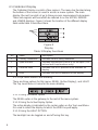
The following table shows which functions are available concurrently.
An X in a column indicates that the mode in the active display will not be
available for selection if the mode in that row is in use in any other display.
Table 4 Mode Concurrency
CURRENT DISPLAY
OTHER DISPLAYS
P[1]
[EXT]
P[1]
ST
[EXT]
ST
mA
mA
Loop
Volts
P[1]ST
X
X
X
X
X
[EXT]ST
X
X
X
X
X
mA
X
X
X
X
mA Loop
X
X
X
Volts
X
X
X
RTD
P[1]
[EXT]
X
X
RTD
X = Not a valid combination
2.1.1.3 Accessing Other Menus
Use the MORE option on the Main Menu to access the other menu
functions.
2.2 Using the Backlight
The backlight is controlled by the LIGHT softkey on the main menu on the
models with electric pump and a dedicated backlight key for manual pump
units. It toggles on and off when the key is pressed; this is one of the few
functions that cannot be controlled by the serial interface. There is a user
defined timer configuration setting for the backlight in the function menus.
2.3 Using the Zero Function
When the ZERO KEY is pressed, the calibrator will zero the active display
if a pressure mode is selected, and the pressure is within the zero limit. The
zero limits are within 5% of the full scale range of the selected sensor. If the
display indicates “OL,” the zero function will not operate.” Note: The ZERO
KEY is only used for pressure.
2.3.1 Internal Sensor and Pressure Module (non-absolute)
When a sensor or module is selected on the active display and the ZERO
KEY is pressed the calibrator subtracts the current reading from the output.
The zero limits are within 10% of the full scale range of the selected sensor.
If the display indicates “OL,” the zero function will not operate.
8
2.3.2 Absolute Internal Sensor or Absolute Pressure Module
When an absolute pressure sensor is selected on the current display and the
ZERO KEY is pressed the calibrator displays the current barometric pressure
on the lower display. At this point the user has two options. With the port
open (vented) to atmosphere, and with access to a high accuracy barometric
reference, the user can utilize the cursor keys to adjust the current value to
the barometric reference pressure and store it in the calibrator using the SET
key. The second option is to use the RESET key to return the barometric
offset to the factory setting. After pressing either the SET or RESET key the
user will be prompted to either confirm or cancel their selection.
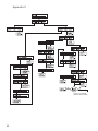
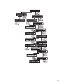
2.4 Other Menu Controlled Functions
There are ‘sub-main’ menus that can be accessed through the MORE option
of the Main Menu. A ‘sub-main’ menu contains three options. The first
option is unique to the function. The second and third options of a ‘submain’ menu are always the same. The NEXT option leads to the next ‘submain’ menu and the DONE option returns home . For the last ‘sub-main’
menu the NEXT option wraps around to home. See Appendix X for a
detailed mapping of the menu structure.
A note on naming convention:
If a ‘sub-main’ menu has subordinate menus, it will henceforth be referred to
as {function} Main Menu. E.g. the display contrast sub-main menu will be
called the Contrast Main Menu. If not it will be called the {function} menu.
9
Menu Functions Overview
2.4.01 %ERROR, on line calculation of sensors error % ...................
2.4.02 LEAK TEST, automatic leak test timer function ........................
2.4.03 MINMAX, min / max hold ....................……….………..............
2.4.04 CONTRAST, display contrast adjustment ...........……………...
2.4.05 LOCK CFG, instrument setup lock ......................…….............
2.4.06 SETUPS, store or recall of setups ...…….................................
2.4.07 AUTO OFF, setup of automatic off timer ......……...............…..
2.4.08 DISPLAY, setup numbers of display windows .........................
2.4.09 PROBE TYPE, Setup of temperature sensor type ...................
2.4.10 DAMP, normal or slow display update rate .............................
2.4.11 HART, switches hart resistor on and off ..................................
2.4.12 RESULOTION, select display resolution .................................
2.4.13 PUMP, setup of electrical pump ..............................................
Page 10
Page 12
Page 14
Page 15
Page 15
Page 15
Page 16
Page 16
Page 17
Page 18
Page 18
Page 18
Page 19
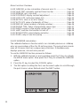
2.4.01 %ERROR calculation
The calibrator features a function which can calculate pressure vs. milliamp
error as a percentage of the 4 to 20 mA loop span. The percent error mode
uses all 3 screens and has a unique menu structure. It simultaneously
displays pressure, mA and error percent.
To use the %ERROR function proceed as follows:
1. With the calibrator turned on and operating press the F3 key to activate
the MORE menu option. Now press the F1 key to activate the %ERROR
option.
2. Press the F1 key to select the CONFIG option.
3. The first option is setting the Port, use the select option to scroll through
the port choices, when finished select the NEXT option.
10
4. LOOP POWER can be toggled on/off, select NEXT when done.
5. Use SELECT to toggle through the UNIT options, and select NEXT to
move on.
6. Use the cursor keys to set the 100% point of the desired pressure range,
select DONE SET when finished.
11
7. Again, use the cursor keys to set 0% point and select DONE SET when
finished and the %ERROR mode will be ready to use.
Note: The 0% and 100% point will be saved in non-volatile memory until
they are changed again by the user for the internal sensors and external
pressure modules. When using an external module the 0% and 100% are
set to low and full scale of the module until the user changes it, or if it was
previously saved.
EXIT leaves the %ERROR mode
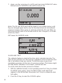
2.4.02 LEAK TEST
The calibrator features a leak test function which calculate leak rate. The
timer can be set from 5 to 120 seconds, regardless of the set time the leak
rate is calculated in leak per minute. The function gives a good and
repeatable expression for the leak of a pressure system. This feature might
be used before calibration to document / indicate leak rate.
To use the leak rate function proceed as follows:
1. With the calibrator turned on and operating press the F3 key to activate
the MORE menu option. Press the NEXT button until LEAK TEST
appears in the left text field. Now press the F1 key to activate the leak
test option.
2. Press the F2 key to select the CONFIG option.
12
3. The first option is setting the Port, use the select option to scroll through
the port choices, when finished select the NEXT option.
4. Use SELECT to toggle through the UNIT options, and select NEXT to
move on.
5. Use cursor keys to set test time, and press DONE SET to confirm.
Note: The units and time will be saved in non-volatile memory until they are
changed again by the user. They may be used at the next leak test without
having to do the configuration each time.
6. To start leak test press F1 button, the time is counted down, and the
Initial, Final and calculated leak rate in pressure per minute is shown.
13
EXIT leaves the leak rate function.
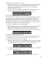
2.4.03 MIN MAX hold
The JOFRA HPC600 Pressure Calibrators have a min/max feature for
capturing the minimum and maximum values of any displayed parameter.
To use the MIN / Max storage function proceed as follows:
1. With the calibrator turned on and operating press the F3 key to activate
the MORE menu option. Press the NEXT button until MINMAX appears
in the left text field, now press the F1 key to activate the Min / Max
storage function.
2. After the Min / Max has been activated, pressing the F1 key will toggle
the display through the min/max values that are stored in the min/max
registers. These readings are live so that the new min/max values will be
recorded while in this mode. To reset the min/max registers simply
press the clear key. These registers are also cleared at power-up, when
pressure is zeroed or when the configuration is changed.
The Min / Max mode is cancelled by pressing F3
14
2.4.04 Setting the Display Contrast
1. With the calibrator turned on and operating press the F3 key to activate
the MORE menu option. Press the NEXT button until CONTRAST
appears in the left text field, now press the F1 key to activate the
contrast adjustment function.
2. Use the cursor keys to adjust the display contrast to the desired level
and then use the CONTRAST DONE option to return home.
2.4.05 Locking and Unlocking Configurations
When the LOCK CFG option is chosen the menu display returns home and
the CONFIG option on the Main Menu indicates that it is locked. Also all
menus are locked out with the exception of the %ERROR, LEAK TEST,
MINMAX, and CONTRAST menus and the Configuration Lock Menu. When
the UNLOCK CFG option is chosen the configuration is unlocked and the
menu display continues to the next sub-main menu.
To use the Locking function proceed as follows:
1. With the calibrator turned on and operating press the F3 key to activate
the MORE menu option. Press the NEXT button until LOCK CFG
appears in the left text field. Now press the F1 key to activate the
function. To reactivate the function use UNLOCK CFG in the same way.
2.4.06 Saving and Recalling Setups
The calibrator will automatically save the current set-up for recall at powerup. Additionally 5 set-ups can be accessed through the SETUPS menu.
To use the Set-up function proceed as follows:
1. With the calibrator turned on and operating press the F3 key to activate
the MORE menu option. Press the NEXT button until SETUPS appears
in the left text field. Now press the F1 key to enter the function.
2. Choose SAVE to save a set-up, RECALL to recall the set-up, or DONE to
do nothing and return home.
If SAVE or RECALL is selected use the cursor keys to select the set-up
15
location. Then use the save option to store the current set-up into the
selected location or the recall option to recall the set-up stored in the
selected location. The display menu will automatically go home.
2.4.07 Setting AutoShut-off Parameters
The calibrator can be set to automatically shut-off after a selected number of
minutes; this function can also be disabled.
To change parameters proceed as follows:
1. With the calibrator turned on and operating press the F3 key to activate
the MORE menu option. Press the NEXT button until AUTO OFF
appears in the left text field. Now press the F1 key to enter the setup.
2. To set the auto shut off parameters select the AUTO OFF option on the
Auto Shut Off Main Menu.
3. Use the cursor keys to select the number of minutes before the calibrator
turns off or disable auto shut-off by scrolling all the way down to 0.
4. Use the AUTO OFF DONE option to set the parameters and return
home. The auto shut off time is reset whenever a key is pressed.
2.4.08 Activating and Deactivating a Display
This is where the number of active measuring windows / channels are
selected, 1, 2 or 3 windows can be selected, to give the optimal mix
between text size, overview and amount of information.
To use the number of windows, proceed as follows:
16
1. With the calibrator turned on and operating press the F3 key to activate
the MORE menu option. Press the NEXT button until DISPLAY appears
in the left text field. Now press the F1 key to enter the function.
2. The NEXT option can be used to select which display to act upon. The
ON/OFF option turns the selected display on or off. The selected display
and current on/off state are displayed in the lower display.
3. Use the DONE option to save the changes and return home. When a
display is deactivated its configuration is retained. When the display is
activated its configuration is checked against the configurations of the
other currently active displays, if the configurations are in conflict the
recalled display's configuration is modified to avoid the conflict. If all
three displays are deactivated the LOWER display will come on automatically.
2.4.09 Setting the RTD probe type
The JOFRA HPC600 has a built in high accuracy RTD thermometer, it works
with an RTD sensor (optional).
To select type of temperature sensor proceed as follows:
1. With the calibrator turned on and operating press the F3 key to activate
the MORE menu option. Press the NEXT button until PROBE TYPE
appears in the left text field. Now press the F1 key to enter the function.
2. There are four probe types to select from P100-385, P100-392, P100-JIS
and CUSTOM. Use the SELECT option to select the desired probe type
and the DONE option to store the change and return home.
Note: The default probe type is PT100-385.
3. Pressing DONE leaves the temperature selection function
17
2.4.10 Switching damping on or off.
To give a more stable reading on fluctuating readings, the HPC600 has a
damping function. This function applies to internal sensors only. When
damping is ON, the calibrator displays a running average reading of ten
measurements. The calibrator takes approximately 3 readings per second.
To switch in or out damping proceed as follows:
1. With the calibrator turned on and operating press the F3 key to activate
the MORE menu option. Press the NEXT button until DAMP appears in
the left text field. Now press the F1 key to enter the setup.
2. Switches damping on or off.
3. DONE returns to main menu.
2.4.11 Switching HART resistor on or off.
An internal 250 ohm HART Resistor can be enabled when the JOFRA
HPC600 is operated in the "mA Measure-24V" mode. This allows a HART
Communicator to be connected across the mA terminals and eliminates the
need for adding an external resistor.
Note: When the HART resistor is on the maximum load driving capacity is
750 ohms.
To change switch in or out the HART resistor proceed as follows:
1. With the calibrator turned on and operating press the F3 key to activate
the MORE menu option. Press the NEXT button until HART appears in
the left text field. Now press the F1 key to enter the setup.
2. Switches the resistor on or off.
3. DONE returns to main menu.
2.4.12 Low resolution function.
Due to the high accuracy of the JOFRA HPC600 the measured values are
displayed with many digits, this might be an disadvantage in some cases,
18
therefore the HPC has a low resolution function. The function takes away the
last digit.
To turn the function on or off, proceed as follows:
1. With the calibrator turned on and operating press the F3 key to activate
the MORE menu option. Press the NEXT button until RESOLUTION
appears in the left text field. Now press the F1 key to enter the function.
2. The select ON or OFF to turn the low resolution function on or off.
3. Pressing DONE returns to main menu.
2.4.13 Pump Limits
To prevent overpressure of sensitive devices the maximum pressure (pump
limit) can be set. When in this mode use the arrow keys to set the maximum
pressure.
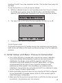
3. Initial Setup and Basic Pressure Generation
1. The JOFRA HPC600 is supplied with a special low volume calibration
hose kit to facilitate faster pumping to pressure and quick pressure
stabilization. the kit also comes with the required “quick-fit” hose
connectors and a BSP adapter for non-NPT applications. It is highly
recommended that this type of hose is used to achieve the best
performance of the product. Once the fittings are installed and the
calibrator is connected to the unit under test (UUT) the calibrator is ready
for use. Figure 5 shows a typical setup.
2. Before generating pressure make sure you have the HPC600 configured
for your application. If needed review section 2 of the manual again to
select the proper configuration.
3. Make sure that the pressure vacuum knob is set for the function you want
to perform (+ for pressure and – for vacuum).
19
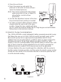
4. Close the vent knob.
5. Press the pump key and watch the
pressure (or vacuum) increase until you
reach the desired pressure.
Note: The motor speed will start slowly
when pressure is low (<15psi) to
allow better control at low
pressures.
6. Use the fine adjustment vernier to fine tune
the pressure/vacuum reading as needed.
7. To reduce or bleed off the pressure entirely
slowly rotate the vent knob to the open
position. Doing this step carefully will allow
you to control the pressure bleed rate to a high degree and will facilitate
taking down-scale pressure readings.
3.1 Electric Pump Considerations
The JOFRA HPC600 a small, lightweight, battery powered pneumatic pump
that allows the user up to 10 bar (150 psi) quickly and with good control.
Because the pump has an upper pressure generation limit of 11 bar
(160psi) there may be atmospheric conditions where it cannot achieve the
full scale pressure of 10 bar. High altitude use (about 3000 ft or 1000
meters) or use at cold temperatures may limit the pump to about 9 bar (135
psi). In these cases the vernier adjustment can be used to generate the
additional pressure needed if full scale pressure must be generated.
In these situations the user should begin the calibration with the vernier in
the full counter clockwise position and then when the electric pump reaches
its limit turn the vernier in the clockwise direction to raise the pressure and
to set the desired reading.
Figure 4
20
4. Measuring Pressure
To measure pressure, connect the calibrator using an appropriate fitting.
Choose a pressure setting for the display being used. The calibrator is
equipped with one internal sensor and many optional external sensors
(APMs) are available. Be sure to choose the sensor based on working
pressures and accuracy.
Note:
Pressure sensors may be damaged and/or personnel injury may occur due
to improper application of pressure. Please refer to the table of ranges and
resolutions at the back of this manual for information on overpressure and
burst pressure ratings. Vacuum should not be applied to any gauge
pressure sensor. The calibrator display will indicate “OL” when an
inappropriate pressure is applied. If “OL” is observed on any pressure
display, the pressure should be reduced or vented immediately to prevent
damage or possible personnel injury. “OL” is displayed when the pressure
exceeds 110% of the nominal range of the sensor or when a vacuum in
excess of 2 PSI is applied on gauge range sensors.
Use the (ZERO) key to zero the pressure sensor when vented to
atmospheric pressure.
Important NOTE: To protect sensor integrity and prevent damage to the
sensor, the calibrator will display OL [overload] when the applied pressure
exceeds 110% of the full scale calibrated range of the sensor.
Important NOTE: To ensure accuracy of the calibrator it is critical to zero
the calibrator before a device is calibrated. See section 2.3.
4.1 Media Compatibility
The JOFRA HPC600 features a unique user accessible valve cleaning port to
facilitate servicing the pump. Section 15.3 shows how to clean these valves.
Even though servicing the pump is easy, care should be taken to only
expose the calibrator to clean, dry gases.
4.2 Measuring Pressure with External Modules
The calibrator provides a digital interface to External Pressure Modules.
These modules are available in various ranges and types including gauge,
vacuum, differential and absolute. The modules work seamlessly with the
calibrator. Simply plug them into the interface and select [EXT] (external
sensor). Since the interface between the calibrator and the module is digital
all the accuracy and display resolution is derived from the module.
21
Figure 5
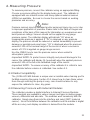
5. Measuring and Generating Current (4 to 20 mA)
1. To measure current use the input terminals in the front of the calibrator.
Select the mA function on the lower display. Current is measured in mA
and percentage of range. The range on the calibrator is set to 0% at 4
mA and 100% at 20 mA.
For example:
If the current measured is displayed as 75% then the mA value is 16
mA.
Note: The display will indicate “OL” when the measured current
exceeds the nominal range of current measurement (24 milliAmps).
2. To source current the same connections are used. From the configuration
screen select mA source or mA Sim-2W.
3. Note that this function can only be done on the LOWER screen. Also in
the source mode the calibrator will generate 0 to 24 mA using its own
internal 24 volt supply whereas in the simulate mode the calibrator acts
as a 2 wire transmitter and requires an external 24 volt supply.
4. Pressing any of the arrow keys will start the output mode and allow you
to use the arrow keys to adjust the mA output.
22
5. While in the mA output mode if the loop is opened or the compliance is
exceeded the unit will flash “OL” .
Figure 6-1
Figure 6-2
Figure 6-3
23
Figure 6-4
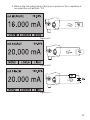
6. Measuring Voltage
To measure voltage use the input terminals in the front of the calibrator.
Select the Volts function on one of the displays. The calibrator can measure
up to 30V.
Note: The display will indicate “OL” when the measured voltage exceeds
the nominal range of voltage measurement (30 V).
Figure 7
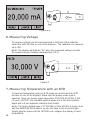
7. Measuring Temperature with an RTD
To measure temperature using an RTD probe you must select the RTD
function on one of the displays. Make sure the proper probe type is
selected. There are 4 probe types supported, P100-385, P100-392, P100JIS and CUSTOM. The standard optional probe has a 250 mm insertion
depth with a 4 mm diameter stainless steel sheath.
24
Note: The factory default type is PT100-385 so if the HPC600 is being used
with the AMETEK/JOFRA sensor you do not have to set the probe type.
Simply plug the probe into the HPC600 and configure the display to read
temperature.
Note: The display will indicate "OL" when the measured temperature is
outside the nominal measurement range of the RTD function (below -40°C or
above 155°C).
If a custom probe is being used, or adjustment of a standard probe is
wanted, entering of CvD parameters, R0 and coefficients is handled through
the serial interface, see remote programming manual.
Figure 8
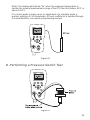
8. Performing a Pressure Switch Test
Figure 9
25
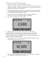
To perform a switch test, follow these steps:
1. Change the setup to Setup 4 (default switch test).
Setup 4: The upper display is set to [P1] ST, all other displays are off.
Important NOTE: The pressure Switch Test can be performed with the
following functions[P1] ST, or EXT ST.
2. Connect the calibrator to the switch using the pressure switch terminals.
The polarity of the terminals does not matter. Then connect the pump
to the calibrator and the pressure switch.
3. Make sure the vent on the pump is open. Zero the calibrator if
necessary. Close the vent after zeroing the calibrator.
4. The top of the display will read “CLOSE”.
5. Apply pressure with the pump slowly until the switch opens.
Important NOTE: In the switch test mode the display update rate is
increased to help capture changing pressure inputs. Even with this
enhanced sample rate pressurizing the device under test should be done
slowly to ensure accurate readings.
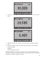
6. Once the switch is open, “OPEN” will be displayed, bleed the pump
slowly until the pressure switch closes.
7. At the top of the display it will now read, “SW OPENED AT” and give
you the pressure that the switch opened at.
26
8. Press the “NEXT” option to view when the switch closed, and the dead
band.
9. Press the “NEW TEST” option to clear the data and perform another
test.
10. Press the “DONE” option to end the test and return to the standard
pressure setting.
Example:
[P1] ST will return to [P1].
Important NOTE: The previous example uses a normally closed switch.
The basic procedure is still the same for a normally open switch, the display
will just read “OPEN” instead of “CLOSE”.
27
9. Calibrating Transmitters
9.1 Using the mA Input Function
The mA input function allows the user to read back the 4-20 mA output from
the device being calibrated. This can be done in one of two ways.
1) Passively – Where the device under test directly generates 4-20 mA and
can be read by the calibrator.
2) Actively – Where the calibrator supplies 24 VDC loop power to the device
under test to power the device while reading the resulting 4-20 mA signal.
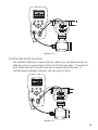
9.2 Calibrating a Pressure-to-Current Transmitter
To calibrate a pressure-to-current transmitter (P/I), perform the following
steps:
1. Connect the calibrator and the pump to the transmitter.
2. Apply pressure with the pump.
3. Measure the current output of the transmitter.
4. Ensure the reading is correct. If not, adjust the transmitter as
necessary.
28
Figure 10.
9.3 Percent Error Function
The calibrator features a unique function which can calculate pressure vs.
milliamp error as a percentage of the 4 to 20 mA loop span. The percent
error mode uses all 3 screens and has a unique menu structure. It
simultaneously displays pressure, mA and percent error.
Figure 11.
29
Example:
Suppose a pressure transmitter under test is 30 psi (2 Bar) full scale and
outputs a corresponding 4 to 20 mA signal. The user can program in a 0 to
30 psi pressure span into the calibrator and the calibrator will calculate and
display the deviation or % Error from the expected 4 to 20 mA output. This
eliminates the need for manual calculations and also helps if it becomes
difficult to set an exact pressure with the pump.
To use the %ERROR function proceed as follows:
1. With the calibrator turned on and operating press the F3 key to activate
the MORE menu option. Now press the F1 key to activate the %ERROR
option.
2. Press the F1 key to select the CONFIG option.
3. The first option is setting the Port, use the select option to scroll through
the port choices, when finished select the NEXT option.
4. LOOP POWER can be toggled on/off, select NEXT when done.
5. Use SELECT to toggle through the UNIT options, and select NEXT to
move on.
30
6. Use the arrow keys to set the 100% point of the desired pressure range,
select DONE SET when finished.
7. Again, use the arrows to set 0% point and select DONE SET when
finished and the %ERROR mode will be ready to use.
Note: The 0% and 100% point will be saved in non-volatile memory until
they are changed again by the user for the internal sensors, and external
pressure modules. When using an external module the 0% and 100% are
set to low and full scale of the module until the user changes it, or if it was
previously saved.
31
10. Minimum and Maximum Storage Capability
The HPC600 has a min/max feature for capturing the minimum and
maximum values of any displayed parameter.
The min/max function can be accessed by stepping through the menu
options until “min/max” is shown on the display above the F1 key. At this time,
pressing the F1 key will toggle the display through the min/max values that
are stored in the min/max registers. These readings are live so that the new
min/max values will be recorded while in this mode.
To reset the min/max registers simply press the clear key. These registers
are also cleared at power-up or when the configuration is changed.
11. Leak Test
The calibrator features a leak test function which calculates leak rate. The
timer can be set from 5 to 120 seconds, regardless of the set time the leak
rate is calculated in leak per minute. The function gives a good and
repeatable expression for the leak of a pressure system. This feature might
be used before calibration to document / indicate leak rate.
To use the leak rate function proceed as follows:
32
1. With the calibrator turned on and operating press the F3 key to activate
the MORE menu option. Press the NEXT button until LEAK TEST appears
in the left text field. Now press the F1 key to activate the leak test option.
2. Press the F2 key to select the CONFIG option.
3. The first option is setting the Port, use the select option to scroll through
the port choices, when finished select the NEXT option.
4. Use SELECT to toggle through the UNIT options, and select NEXT to
move on.
5. Use cursor keys to set test time, and press DONE SET to confirm.
Note: The units and time will be saved in non-volatile memory until they are
changed again by the user. They may be used at the next leak test without
having to do the configuration each time.
33
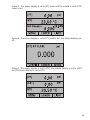
6. To start leak test press F1 button, the time is counted down, and the
Initial, Final and calculated leak rate in pressure pr. Minute is shown.
EXIT leaves the leak rate function.
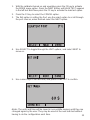
12. Factory Setups
The Calibrator is loaded with five factory commonly used setups. These
setups are shown below. Note: Any of these setups can be changed
and saved by the user.
Setup 1: The upper display is set to [P1] mode and the lower is set to mA,
middle is off.
Setup 2: The upper display is set to [P1] mode and the lower is set to RTD,
middle is off.
34
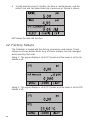
Setup 3: The upper display is set to [P1] mode and the middle is set to RTD,
lower is mA.
Setup 4: The lower display is set to [P1] switch test, the other displays are
off.
Setup 5: The upper display is set to [P1], the middle display is set to [EXT]
and the lower display is set to RTD.
35
13. Custody Transfer / Flow Calibration
The Model HPC600 is ideal for flow computer calibration. Every
manufacturer of flow computers has a different calibration procedure, but
most call for calibration of three parameters: static pressure, differential
pressure and temperature. To facilitate these measurements recall setup #5
on the HPC600.
1. Connect the calibrator to your static and differential pressures. ([P1],
EXT) Then connect the RTD sensor to the calibrator.
2. Using the reading of your RTD, static, and differential pressures make
sure the flow computer has the correct reading. If not, adjust the flow
computer as necessary.
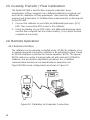
14. Remote Operation
14.1 Remote Interface
The calibrator can be remotely controlled using JOFRACAL software, or by
a computer program running the calibrator in an automated system. It uses
an RS232 serial port connection for remote operation. NOTE: The special
RS232 cable is an option (Communication kit with cable and JOFRACAL
software), and are used for adjustment procedures too. A detailed
communication manual can be downloaded on www.jofra.com.
Typical RS232 remote configurations are shown in Figure 12.
Figure 12. Calibrator-to-Computer Connection
36
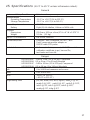
15. Specifications
(15 °C to 35 °C unless otherwise noted.)
General
Instrument Setup Recall
5; last used on power-up
Environmental
Operating Temperature
Storage Temperature
-10 °C to +50 °C (14 to 122 ºF)
-20 °C to +60 °C (4 to 140 ºF)
Power Requirements
Battery
12 VDC
Eight (8) AA alkaline, Lithium or NiMh cells
Physical
Dimensions
Weight
(20.3cm x 10.2cm x 6cm) 8” H x 4” W x 2.375” D
2.5 lbs. (1.2 kg)
EMI/RFI Conformance
EN 61326, Annex A
Connectors/Ports
Pressure - one, combined 1/8" NPT / BSP
Port-P pressure module adapter or
RS232 cable RTD probe
Included Accessories
Soft case, batteries, manual, full NIST-traceable
calibration certificate in psi, bar and Pa,
test leads and hose kit.
Ranges
HPC600
HPC600
HPC600
HPC600
002C
002A
010C
010A
-0.82 to 2 bar (-12 to 30 psi) Compound
0.2 to 2 bar ( 3 to 30 psi) Absolute
-0.82 to 10 bar (-12 to 150 psi) Compound
0.2 to 10 bar (3 to 150 psi) Absolute
mA
0 to 24.000 mA measure and source
Volts
0 to 30.000 VDC
RTD
-40.0°C to 155.0°C
(-40.0°F to 311.0°F)
Engineering Units
psi, bar, mbar, kPa, MPa, kgcm2, mmH2O @ 4°C,
mmH2O @ 20°C, cmH2O @ 4°C, cmH2O @ 20°C,
inH2O @ 4°C, inH2O @ 20°C, inH2O @ 60°F,
mmHg @ 0°C, inHg @ 0°C
37
Accuracy
Pressure
All Ranges
±0.02% of reading ±0.015%FS (18°C to 28°C)
±0.03% of reading ±0.015%FS (-10°C to 55°C)
Vacuum
All Ranges
±0.025% FS (18°C to 28°C)
±0.035% FS (-10°C to 55°C)
mA
±0.015% of reading ±0.002mA
Volts
±0.015% of reading ±0.002V
RTD (ohms)
±0.015% of rdg ±0.02 ohms; or ±0.1°C @ 0°C for
Pt100
Temperature Effect (mA, volts, RTD)
No effect on accuracy from 18°C to 28°C
Add ±0.001% F.S. for temps <18°C and >28°C
Option T, RTD probe
Accuracy ± 0.15 °C @ -40 to 155 °C
16. Maintenance
16.1 Replacing Batteries
Replace batteries as soon as the battery indicator turns on to avoid false
measurements. If the batteries discharge too deeply the JOFRA HPC600 will
automatically shut down to avoid battery leakage.
Note: Use only AA size alkaline or Lithium batteries or optional
rechargeable NiMh cells.
16.2 Cleaning the Unit
Warning
To avoid personal injury or damage to the calibrator, use only the specified
replacement parts and do not allow water into the case.
Caution
To avoid damaging the plastic lens and case, do not use solvents or
abrasive cleansers.
Clean the calibrator with a soft cloth dampened with water or water and mild
soap.
16.3 Valve Cleaning Procedure
Occasionally, the JOFRA HPC600 may not work properly due to dirt or other
contamination of the internal valve assembly. Use the following procedure
for cleaning the valve assembly. If this procedure does not fix the problem, a
38
repair kit (part number 1010043) may be ordered.
1. Using a small screwdriver, remove the 2 valve retention caps located in
the battery compartment area (see Figure 1, page 4).
2. After the caps have been removed, gently remove the spring and
o-ring assembly.
3. Set aside the valve assemblies in a safe area and clean out the valve
body using a cotton swab soaked in IPA (isopropyl alcohol).
4. Repeat the process several times using a new cotton swab each time
until there is no remaining evidence of contamination or dirt.
5. Operate the pump handles several times and recheck for contamination.
6. Clean the o-ring assembly and the o-ring on the retention caps with IPA
and inspect the o-rings closely for any damage or excessive wear.
Replacements are included in the repair kit, if needed.
7. Inspect the springs for wear or loss of tension. They should be
approximately 8.6 mm long in the relaxed state. If shorter, they may not
provide sufficient sealing tension. Replace if needed.
8. Once all parts have been cleaned and inspected, reinstall the o-ring and
spring assembly into the valve body.
9. Reinstall the retention caps and gently tighten each cap.
10. Seal the output port and operate the pump to at least 50% of capacity.
11. Release the pressure and repeat several times to ensure that the
o-rings seat properly.
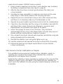
16.4 Service Center Calibration or Repair
Only qualified service personnel should perform calibration, repairs, or
servicing not covered in this manual. If the calibrator fails, check the
batteries first, and replace them if needed.
Verify that the calibrator is being operated as explained in this manual. If the
calibrator is faulty, send a description of the failure with the calibrator. Be
sure to pack the calibrator securely, using the original shipping container if it
is available.
39
Appendix X
40
41
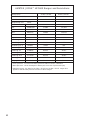
AMETEK JOFRA™ HPC600 Ranges and Resolutions
Range (PSI)
2.0 Bar / 30 PSI
10 Bar / 150 PSI
Burst Pressure (PSI)
300
300
Proof Pressure (PSI)
60
200
Engineering Unit
Factor
Psi
1
30.000
150.00
bar
0.06894757
2.0684
10.3421
mbar
68.94757
2068.4
10342.1
kPa
6.894757
206.84
1034.21
MPa
.00689476
0.2068
1.03421
kg/cm2
0.07030697
2.1092
10.5460
cmH2O @ 4°C
70.3089
2109.3
10546.3
cmH2O @ 20°C
70.4336
2113.0
10565.0
mmH2O @ 4 °C
703.089
21093
N/A
mmH2O @ 20°C
704.336
21130
N/A
inH2O @ 4°C
27.68067
830.42
4152.1
inH2O @ 20°C
27.72977
831.89
4159.5
inH2O @ 60°F
27.70759
831.23
4156.1
mmHg @ 0°C
51.71508
1551.5
7757.3
inHg @ 0°C
2.03602
61.081
305.40
• Proof pressure - maximum allowable pressure without a shift in calibration
• Burst pressure - sensor damaged or destroyed; some risk of personnel injury
• Absolute ranges - the data for the 2 Bar / 30 PSI and 10 Bar / 50 PSI ranges also
applies to the absolute pressure versions of those ranges.
42
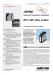
AMETEK Calibration Instruments
One of the world’s leading manufacturers and developers
of calibration instruments for temperature, pressure and
process signals as well as for temperature sensors both
from a commercial and a technological point of view.
JOFRA Temperature Instruments
Portable precision thermometers. Dry-block and
liquid bath calibrators: 4 series, with more than
25 models and temperature ranges from
-90° to 1205°C/-130° to 2200°F.
JOFRA Pressure Instruments
Convenient electronic systems ranging from
-1 to 1000 bar - multiple choices of pressure ranges,
pumps and accuracies, fully temperature-compensated
for problem-free and accurate field use.
JOFRA Signal Instruments
Process signal measurement and simulation for easy
control loop calibration and measurement tasks - from
handheld field instruments to laboratory reference level
bench top instruments.
JOFRA Marine Instruments
A complete range of calibration equipment for
temperature, pressure and signal, approved for marine
use.
FP Temperature Sensors
A complete range of temperature sensors
for industrial and marine use.
M&G Pressure Testers
Pneumatic floating-ball or hydraulic piston dead weight
testers with accuracies to 0.015% of reading.
M&G Pumps
Pressure generators from small pneumatic “bicycle” style
pumps to hydraulic pumps generating up to 1,000 bar.
www.jofra.com
Headquarters:
AMETEK Denmark A/S
Gydevang 32-34 • 3450 Allerød • Denmark
Tel: +45 4816 8000 • [email protected]
Sales & Service:
Europe, Asia, Africa, Middle East and South America
Sales & Service Offices:
AMETEK Mansfield & Green (North America)
Tel: +1 800 527 9999 • [email protected]
AMETEK Singapore Pte. Ltd. (Singapore)
Tel: +65 6 484 2388 • [email protected]
AMETEK Inc. Beijing Rep. Office (China)
Tel: +86 10 8526 2111 • [email protected]
AMETEK GmbH (Germany)
Tel: +49 2159 9136 510 • [email protected]
Information in this document is subject to change without notice.
©2009, by AMETEK, Inc., www.ametek.com. All rights reserved.
AMETEK Calibration Instruments (UK)
Tel: +44 (0) 1243 833 302 • [email protected]