1
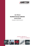
User Manual
Handheld Pressure Calibrator
JOFRA HPC550Ex & HPC552Ex
HPC550 Ex/552 Ex
Reference Manual
1. Introduction . . . . . . . . . . . . . . . . . . . . . . . . . . . . . . . . . . . . . . . . . . . .1
1.1 Contacting AMETEK . . . . . . . . . . . . . . . . . . . . . . . . . . . . . . . . . . . . . . . .1
1.2 Standard Equipment . . . . . . . . . . . . . . . . . . . . . . . . . . . . . . . . . . . . . . .1
1.3 Safety information . . . . . . . . . . . . . . . . . . . . . . . . . . . . . . . . . . . . . . . . .2
2. Calibrator Interface . . . . . . . . . . . . . . . . . . . . . . . . . . . . . . . . . . . . . .5
2.1 Calibrator Display . . . . . . . . . . . . . . . . . . . . . . . . . . . . . . . . . . . . . . . . .7
2.2 Using the Backlight . . . . . . . . . . . . . . . . . . . . . . . . . . . . . . . . . . . . . . . .9
2.3 Using the Zero Function . . . . . . . . . . . . . . . . . . . . . . . . . . . . . . . . . . . .9
2.4 Menu Controlled Functions . . . . . . . . . . . . . . . . . . . . . . . . . . . . . . . . .10
3. Measuring Pressure . . . . . . . . . . . . . . . . . . . . . . . . . . . . . . . . . . . . .23
3.1 Media Compatibility . . . . . . . . . . . . . . . . . . . . . . . . . . . . . . . . . . . . . . .24
4. Measuring Current . . . . . . . . . . . . . . . . . . . . . . . . . . . . . . . . . . . . . .24
5. Measuring Temperature with an RTD . . . . . . . . . . . . . . . . . . . . . . .24
6. Performing a Pressure Switch Test . . . . . . . . . . . . . . . . . . . . . . . . .26
7. Calibrating Transmitters . . . . . . . . . . . . . . . . . . . . . . . . . . . . . . . . .29
7.1 Using the mA Input Function . . . . . . . . . . . . . . . . . . . . . . . . . . . . . . . .29
7.2 Calibrating a Pressure-to-Current Transmitter . . . . . . . . . . . . . . . . . . . .29
7.3 Percent Error Function . . . . . . . . . . . . . . . . . . . . . . . . . . . . . . . . . . . . .30
8. Minimum and Maximum Storage Capability . . . . . . . . . . . . . . . . . .33
9. Factory Setups . . . . . . . . . . . . . . . . . . . . . . . . . . . . . . . . . . . . . . . . .34
10. Custody Transfer / Flow Calibration . . . . . . . . . . . . . . . . . . . . . . .36
11. Specifications . . . . . . . . . . . . . . . . . . . . . . . . . . . . . . . . . . . . . . . . .37
12. Maintenance . . . . . . . . . . . . . . . . . . . . . . . . . . . . . . . . . . . . . . . . . .40
12.1 Replacing Batteries . . . . . . . . . . . . . . . . . . . . . . . . . . . . . . . . . . . . . .40
12.2 Cleaning the Unit . . . . . . . . . . . . . . . . . . . . . . . . . . . . . . . . . . . . . . . .41
12.3 Service Center Calibration or Repair . . . . . . . . . . . . . . . . . . . . . . . . .41
1. Introduction
The JOFRA HPC550 Ex/552 Ex is a high accuracy, full function pressure
calibrator. The calibrator includes the following features and functions:
• Large graphical LCD display. Intuitive menu system for easy operation of the
large number of unique and handy functions and features. The HPC550
Ex/552 Ex is available with one or two built-in sensors, to obtain the best
possible solution for your requirements.
• Switch test functionality uses a high speed pressure update rate for superior
performance and repeatability.
• Current measurement.
• Temperature measurement capability (Probe optional).
• The HPC550 Ex/552 Ex is available in a great number of pressure ranges,
and types. Please see pressure range/accuracy table for further details (Page
39). Vacuum is supported in all units up to 35 bar / 500 psi.
Read this manual carefully before using the instrument and make
sure that all safety instructions and warnings are observed.
1.1 Contacting AMETEK/JOFRA
US, Canada, Latin America
Europe, Africa, Middle East
Asia
AMETEK M&CT 1-800-527-9999
AMETEK Denmark A/S + 45 4816 8000
AMETEK Singapore Pte. Ltd.
At + 65 (64) 842 388
1.2 Standard Equipment
Inspect the unit carefully upon receipt. Save packing carton in case reshipment
is necessary. If there appears to be any damage, equipment missing or if there
are any questions about the unit, contact AMETEK.
Check to see if your calibrator is complete. It should include:
• HPC550 Ex/552 Ex Calibrator
• Reference Manual
• Test Leads
• Pressure Fittings
• Calibration Certificate
1.3 Safety information
Ex Hazardous Areas
An Ex-hazardous area as used in this manual refers to an area made
hazardous by the potential presence of flammable or explosive vapors. These
areas are also referred to as hazardous locations.
1
The HPC550 Ex/552 Ex calibrator has been designed for use in Ex
Hazardous Areas. These are areas where potentially flammable or explosive
vapors may occur. These areas are referred to as hazardous (classified)
locations in the United States, as Hazardous Locations in Canada, as
Potentially Explosive Atmospheres in Europe and as Explosive Gas
Atmospheres by most of the rest of the world. The HPC550 Ex/552 Ex
calibrator is designed as intrinsically safe. This means that connecting the
HPC550 Ex/552 Ex calibrator to equipment that is used within intrinsically
safe circuits will not cause an ignition capable arc as long as the entity
parameters are suitably matched.
Warning
Check entity parameters before making any connections to this device.
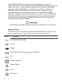
Symbols Used
The following table lists the International Electrical Symbols. Some or all of
these symbols may be used on the instrument or in this manual.
Symbol
Description
AC (Alternating Current)
AC-DC
Battery
CE Complies with European Union Directives
DC
Double Insulated
Electric Shock
Fuse
PE Ground
2
Hot Surface (Burn Hazard)
Read the User’s Manual (Important Information)
Off
On
The following definitions apply to the terms “Warning” and “Caution”.
• “Warning” identifies conditions and actions that may pose hazards to the
user.
• “Caution” identifies conditions and actions that may damage the
instrument being used.
Use the calibrator only as specified in this manual, otherwise injury and
damage to the calibrator may occur.
Warning
To avoid possible electric shock or personal injury:
• Do not apply more than the rated voltage. See specifications for supported
ranges.
• Follow all equipment safety procedures.
• Never touch the probe to a voltage source when the test leads are
plugged into the current terminals.
• Do not use the calibrator if it is damaged. Before you use the calibrator,
inspect the case. Look for cracks or missing plastic. Pay particular
attention to the insulation surrounding the connectors.
• Select the proper function and range for your measurement.
• Make sure the battery cover is closed and latched before you operate the
calibrator.
• Remove test leads from the calibrator before you open the battery door.
• Inspect the test leads for damaged insulation or exposed metal. Check
test leads continuity. Replace damaged test leads before you use the
calibrator.
• When using the probes, keep your fingers away from the probe contacts.
Keep your fingers behind the finger guards on the probes.
• Connect the common test lead before you connect the live test lead.
When you disconnect test leads, disconnect the live test lead first.
3
• Do not use the calibrator if it operates abnormally. Protection may be
impaired. When in doubt, have the calibrator serviced.
• Do not operate the calibrator around explosive gas, vapor, or dust beyond
the specified ranges.
• When measuring pressure, make sure the process pressure line is shut off
and depressurized before you connect it or disconnect it from the
pressure sensor.
• Disconnect test leads before changing to another measure or source
function.
• When servicing the calibrator, use only specified replacement parts.
• To avoid false readings, which could lead to possible electric shock or
personal injury, replace the battery as soon as the battery indicator
appears
Caution
To avoid possible damage to calibrator or to equipment under test:
• Use the proper jacks, function, and range for your measurement or
sourcing application.
4
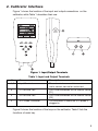
2. Calibrator Interface
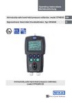
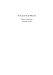
Figure 1 shows the location of the input and output connections on the
calibrator, while Table 1 describes their use.
Figure 1. Input/Output Terminals
Table 1: Input and Output Terminals
No.
Name
Description
1, 2
Input Terminals
These terminals are used to measure current
and a contact closure for switch test.
3
P1 Pressure Port
This is the connection for the internal sensor
[P1]
4
P2 Pressure Port
This is the connection for the internal sensor
[P2]
5
RTD Probe Connector
This connector is where the RTD probe is
plugged in.
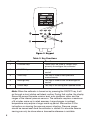
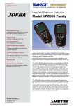
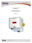
Figure 2 shows the location of the keys on the calibrator. Table 2 lists the
functions of each key.
5
Figure 2. Keypad
Table 2. Key Functions
No.
Name
Function
1
Function Keys
These keys are used in various ways,
primarily to configure the calibrator
2
ON/OFF Key
This key is used to turn the calibrator on
and off
3
ZERO Key
This key is used to zero pressure
measurements
4
Backlight Key
This key is used to turn the backlight on
and off
5
Cursor Keys
This key is for setting user inputed values
Note: When the calibrator is turned on by pressing the ON/OFF key, it will
go through a short startup self-check routine. During that routine, the display
shows the current firmware revision level, auto shutdown status and the
ranges of the internal pressure sensors. The calibrator requires a maximum
of 5 minutes warm-up to rated accuracy. Large changes in ambient
temperature may require a longer warm-up period. See section 2.3 for
instructions on zeroing the pressure sensor displays. Pressure ranges
should be zeroed each time the calibrator is started. For aboslute sensors
zeroing can only be done when a barometric reference is available.
6
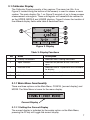
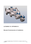
2.1 Calibrator Display
The Calibrator Display consists of two regions: The menu bar (No. 5 on
Figure 3, located along the bottom of the screen) is used to access a menu
system. The main display (No. 1 on Figure 3) consists of up to three process
measurement sub-regions. These sub-regions will henceforth be referred to
as the UPPER, MIDDLE and LOWER displays. Figure 3 shows the location of
the different display fields while table 3 describes them.
Figure 3. Display
Table 3: Display Functions
No.
Name
Description
1
Primary Parameters
Indicates what is being measured.
2
Span Indicator
Indicates the percent of the 4 to 20 mA
span.
3
Pressure Units
Indicates one of 15 pressure units available
for display.
4
Units
Indicates the unit of measure for the display.
5
Menu bar
Access to menu systems
2.1.1 Main Menu Functionality
There are three options on the Main Menu, CONFIG, {current display} and
MORE. The Main Menu is home for the menu display.
Current Display
2.1.1.1 Setting the Current Display
The current display is indicated by the center option on the Main Menu,
pressing the F2 key will toggle the current display.
7
2.1.1.2 Setting Current Display Parameters
To set the parameters of the current display use the CONFIG option to get
to the Display Configuration Menu.
Here the SELECT option will toggle through the choices for each parameter.
The first parameter is MODE. Since current and switch test modes all use
the same jacks, two of these functions cannot be used concurrently. The
ability to select certain functions is limited based on what is already selected
in another active display. The NEXT option is used to change to the second
parameter. Only RTD and Pressure modes have a second parameter, RTDs
can be read in Celsius or Fahrenheit and Pressures can be read in 15
engineering units.
With a single display the following modes are available:
P[1] = Pressure on left side sensor.
P[2] = Pressure on right side sensor.
P[1] ST = Switch Test with left side sensor.
P[2] ST = Switch Test with right side sensor.
mA = Milliamps measure.
RTD = RTD Temperature Measurement (if a probe is connected).
The following table shows which functions are available concurrently.
An X in a column indicates that the mode in the current display will not be
available for selection if the mode in that row is in use in any other active
display.
8
Table 4 Mode Concurrency
CURRENT DISPLAY
OTHER DISPLAYS
P[1]
P[2]
P[1]
ST
P[2]
ST
mA
X
X
X
X
RTD
P[1]
P[2]
[Δ/Σ]
P[1]ST
P[2]ST
X
X
mA
X
X
RTD
Note: P2 is only available on the double sensor version of HPC550-Ex/552Ex.
2.1.1.3 Accessing Other Menus
Use the MORE option on the Main Menu to access the other menu
functions.
2.2 Using the Backlight
The backlight is controlled by the dedicated backlight key. It toggles on and
off when the key is pressed; There is a user defined timer configuration
settings for the backlight in the functions menu system (2.4.12)
2.3 Using the Zero Function
When the ZERO KEY is pressed, the calibrator will zero the current display if
a pressure mode is selected, and the pressure is within the zero limit. The
zero limits are within 5% of the full scale range of the selected sensor. If the
display indicates "OL," the zero function will not operate."
2.3.01 Internal Sensor
When a sensor is selected on the current display and the ZERO KEY is
pressed the calibrator subtracts the current reading from the output. The
zero limits are within 5% of the full scale range of the selected sensor. If the
display indicates "OL," the zero function will not operate.
9
2.3.02 Absolute Internal Sensor
When an absolute pressure sensor is selected on the current display and the
ZERO KEY is pressed the calibrator displays the current barometric pressure
on the lower display. At this point the user has two options. With the port
open (vented) to atmosphere, and with access to a high accuracy barometric
reference, the user can utilize the cursor keys to adjust the current value to
the barometric reference pressure and store it in the calibrator using the SET
key. The second option is to use the RESET key to return the barometric
offset to the factory setting. After pressing either the SET or RESET key the
user will be prompted to either confirm or cancel their selection
2.4 Menu Controlled Functions
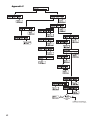
There are 14 'sub-main' menus that can be accessed through the MORE
option of the Main Menu. A 'sub-main' menu contains three options. The first
option is unique to the function. The second and third options of a 'submain' menu are always the same. The NEXT option leads to the next 'submain' menu and the DONE option returns to main window . For the last 'submain' menu the NEXT option wraps around to home. See Appendix X
(pages 41 & 42) Menu Tree, for a detailed mapping of the menu structure.
A note on naming convention:
If a 'sub-main' menu has subordinate menus, it will henceforth be referred to
as {function} Main Menu. E.g. the display contrast sub-main menu will be
called the Contrast Main Menu. If not it will be called the {function} menu.
10
Menu Functions Overview
2.4.01
2.4.02
2.4.03
2.4.04
2.4.05
2.4.06
2.4.07
2.4.08
2.4.09
2.4.10
2.4.11
2.4.12
2.4.13
%ERROR, on line calculation of sensors error % ….. Page 11
LEAK TEST, automatic leak test timer function……….Page 13
MINMAX, min / max hold……………………………… Page 15
Δ/Σ, delta / summary calculation …………………… Page 16
CONTRAST, display contrast adjustment….……….... Page 17
LOCK CFG, instrument setup lock…………………… Page 18
SETUPS, store or recall of setups………….………… Page 18
AUTO OFF, setup of automatic off timer……………... Page 19
DISPLAY, setup numbers of display windows……..... Page 19
PROBE TYPE, Setup of temperature sensor type…… Page 20
RESULOTION, select display resolution……….…….. Page 21
LIGHT TIMER, setup of backlight timer……………… Page 21
DAMP, normal or slow display update rate………….. Page 22
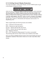
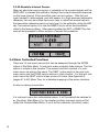
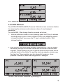
2.4.01 %ERROR calculation
Warning
Check entity parameters before making any connections to this device.
The calibrator features a function which can calculate pressure vs. milliamp
error as a percentage of the 4 to 20 mA loop span. The percent error mode
uses all 3 screens and has a unique menu structure. It simultaneously
displays pressure, mA and error percent.
To use the %ERROR function proceed as follows:
1. With the calibrator turned on and operating press the F3 key to activate
the MORE menu option. Now press the F1 key to activate the %ERROR
option.
2. Press the F1 key to select the CONFIG option.
3. The first option is setting the Port, use the select option to scroll through
the port choices, when finished select the NEXT option.
11
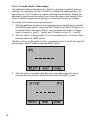
5. Use SELECT to toggle through the UNIT options, and select NEXT to
move on.
6. Use the cursor keys to set the 100% point of the desired pressure range,
select DONE SET when finished.
7. Again, use the cursor keys to set 0% point and select DONE SET when
finished and the %ERROR mode will be ready to use.
12
Note: The 0% and 100% point will be saved in non-volatile memory until
they are changed again by the user for the internal sensors.
EXIT leaves the %ERROR mode
Warning
Check entity parameters before making any connections to this device.
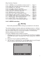
2.4.02 LEAK TEST
Warning
Check entity parameters before making any connections to this device.
The calibrator features a leak test function which calculate leak rate. The
timer can be set from 5 to 120 seconds, regardless of the set time the leak
rate is calculated in leak per minute. The function gives a good and
repeatable expression for the leak of a pressure system. This feature might
be used before calibration to document / indicate leak rate.
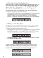
To use the leak rate function proceed as follows:
1. With the calibrator turned on and operating press the F3 key to activate
the MORE menu option. Press the NEXT button until LEAK TEST
appears in the left text field. Now press the F1 key to activate the leak
test option.
2. Press the F2 key to select the CONFIG option.
3. The first option is setting the Port, use the select option to scroll through
the port choices, when finished select the NEXT option.
13
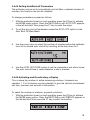
4. Use SELECT to toggle through the UNIT options, and select NEXT to
move on.
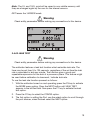
5. Use cursor keys to set test time, and press DONE SET to confirm.
Note: The units and time will be saved in non-volatile memory until they are
changed again by the user. They may be used at the next leak test without
having to do the configuration each time.
6. To start leak test press F1 button, the time is counted down, and the
Initial, Final and calculated leak rate in pressure pr. Minute is shown.
14
EXIT leaves the leak rate function.
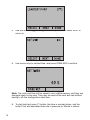
2.4.03 MIN MAX hold
The JOFRA HPC550 Ex/552 Ex Pressure Calibrators have a min/max feature
for capturing the minimum and maximum values of any displayed
parameter.
To use the MIN / Max storage function proceed as follows:
1. With the calibrator turned on and operating press the F3 key to activate
the MORE menu option. Press the NEXT button until MINMAX appears
in the left text field, now press the F1 key to activate the Min / Max
storage function.
2. After the Min / Max have been activated, pressing the F1 key will toggle
the display through the min/max values that are stored in the min/max
registers. These readings are live so that the new min/max values will be
recorded while in this mode. To reset the min/max registers simply press
the clear key. These registers are also cleared at power-up, when
pressure is zeroed or when the configuration is changed.
The Min / Max mode is cancelled by pressing F3
15
2.4.4 Δ/Σ mode (Delta / Sum mode)
The calibrator features the ability to subtract or add two specified pressure
readings. An application of the Δ function is differential measurements. An
application for the Σ function is pseudo absolute measurement. Where the
barometric pressure can be taken by an absolute sensor and added to the
value of another gauge sensor giving you an absolute pressure reading.
To use the Δ/Σ function proceed as follows:
1. With the calibrator turned on and operating press the F3 key to activate
the MORE menu option. Press the NEXT button until SETΔ/Σ appears in
the left text field. Now press the F1 key to activate the function. Please
note Δ function is [port1] - [port2] and Σ function is [port1] + [port2].
2. The first option is setting either Δ or Σ, use select option to chose, when
finished select the NEXT option.
The 2nd option is setting the 1st Port, use select option to scroll through the
port choices, when finished select the NEXT option.
3. The 3rd option is selecting the 2nd port, use select option to scroll
through the port choices, when finished select the NEXT option.
16
4. The Δ/Σ function is now configured, and can be chosen in the main
menu, for the desired display via the normal CONFIG / SELECT
procedure.
Note: The setup will be saved in non-volatile memory until it is changed
again by the user. It may be used at the next leak test without having to do
the configuration each time.
2.4.05 Setting the Display Contrast
1. With the calibrator turned on and operating press the F3 key to activate
the MORE menu option. Press the NEXT button until CONTRAST
appears in the left text field, now press the F1 key to activate the
contrast adjustment function.
2. Use the cursor keys to adjust the display contrast to the desired level
and then use the CONTRAST DONE option to return home.
17
2.4.06 Locking and Unlocking Configurations
When the LOCK CFG option is chosen the menu display returns home and
the CONFIG option on the Main Menu indicates that it is locked. Also all
menus are locked out with the exception of the %ERROR, LEAK TEST,
MINMAX, SET Δ/Σ and CONTRAST menus and the Configuration Lock
Menu. When the UNLOCK CFG option is chosen the configuration is
unlocked and the menu display continues to the next sub-main menu.
To use the Locking function proceed as follows:
1. With the calibrator turned on and operating press the F3 key to activate
the MORE menu option. Press the NEXT button until LOCK CFG
appears in the left text field. Now press the F1 key to activate the
function. To reactivate the function use UNLOCK CFG in the same way.
2.4.07 Saving and Recalling Setups
The calibrator will automatically save the current set-up for recall at powerup. Additionally 5 set-ups can be accessed through the SETUPS menu.
To use the Locking function proceed as follows:
1. With the calibrator turned on and operating press the F3 key to activate
the MORE menu option. Press the NEXT button until SETUPS appears
in the left text field. Now press the F1 key to enter the function.
2. Choose SAVE to save a set-up , RECALL to recall the set-up, or DONE
to do nothing and return home.
If SAVE or RECALL is selected use the cursor keys to select the set-up
location. Then use the save option to store the current set-up into the
selected location or the recall option to recall the set-up stored in the
selected location. The display menu will automatically go home.
18
2.4.08 Setting AutoShut-off Parameters
The calibrator can be set to automatically shut-off after a selected number of
minutes; this function can also be disabled.
To change parameters proceed as follows:
1. With the calibrator turned on and operating press the F3 key to activate
the MORE menu option. Press the NEXT button until AUTO OFF appears
in the left text field. Now press the F1 key to enter the setup.
2. To set the auto shut off parameters select the AUTO OFF option on the
Auto Shut Off Main Menu.
3. Use the cursor keys to select the number of minutes before the calibrator
turns off or disable auto shut-off by scrolling all the way down to 0.
4. Use the AUTO OFF DONE option to set the parameters and return home.
The auto shut off time is reset whenever a key is pressed.
2.4.09 Activating and Deactivating a Display
This is where the number of active measuring windows / channels are
selected, 1, 2 or 3 windows can be selected, to give the optimal mix between
text size, overview and amount of information.
To select the number of windows, proceed as follows:
1. With the calibrator turned on and operating press the F3 key to activate
the MORE menu option. Press the NEXT button until DISPLAY appears in
the left text field. Now press the F1 key to enter the function.
19
2. The NEXT option can be used to select which display to act upon. The
ON/OFF option turns the selected display on or off. The selected display
and current on/off state are displayed in the lower display.
3. Use the DONE option to save the changes and return home. When a
display is deactivated its configuration is retained. When the display is
activated its configuration is checked against the configurations of the
other currently active displays, if the configurations are in conflict the
recalled display's configuration is modified to avoid the conflict. If all
three displays are deactivated the LOWER display will come on
automatically
2.4.10 Setting the RTD probe type
The JOFRA HPC550 Ex/552 Ex have a built in high accuracy RTD
thermometer, it works with an RTD sensor (optional).
To select type of temperature sensor proceed as follows:
1. With the calibrator turned on and operating press the F3 key to activate
the MORE menu option. Press the NEXT button until PROBE TYPE
appears in the left text field. Now press the F1 key to enter the function.
2. There are four probe types to select from P100-385, P100-392, P100-JIS
and CUSTOM. Use the SELECT option to select the desired probe type
and the DONE option to store the change and return home.
Note: The default probe type is PT100-385.
3. Pressing DONE leaves the temperature selection function
20
2.4.11 Low resolution function.
Due to the high accuracy of the JOFRA HPC550 Ex/552 Ex the measured
values are displayed with many digits, this might be an disadvantage in
some cases, therefore the HPC has a low resolution function. The function
takes away the last digit.
To turn the function on or off, proceed as follows:
1. With the calibrator turned on and operating press the F3 key to activate
the MORE menu option. Press the NEXT button until RESOLUTION
appears in the left text field. Now press the F1 key to enter the function.
2. The select ON or OFF to turn the low resolution function on or off.
3. Pressing DONE returns to main menu.
2.4.12 Setting display Light-off Parameters
The calibrator will automatically shut-off the display back light after a
selected number of minutes.
To change parameters proceed as follows:
1. With the calibrator turned on and operating press the F3 key to activate
the MORE menu option. Press the NEXT button until LIGHT TIMER
appears in the left text field. Now press the F1 key to enter the setup.
21
2. Use the cursor up/down keys to select the number of minutes before
the light turns off.
3. When the desired time has been reached, press DONE SET to return to
main menu.
2.4.13 Switching damping on or off.
To give a more stable reading on fluctuating readings, the HPC550 Ex/552
Ex has a damping function. This function applies to internal sensors only.
When damping is ON, the calibrator displays a running average reading of
ten measurements. The calibrator takes approximately 3 readings per
second.
To switch in or out damping proceed as follows:
1. With the calibrator turned on and operating press the F3 key to activate
the MORE menu option. Press the NEXT button until DAMP appears in
the left text field. Now press the F1 key to enter the setup.
2. Switches damping on or off.
3. DONE returns to main menu.
22
3. Measuring Pressure
Warning
Check entity parameters before making any connections to this device.
To measure pressure, connect the calibrator using an appropriate fitting.
Choose a pressure setting for the display being used. The calibrator is
equipped with one or two internal sensors. Be sure to choose the sensor
based on working pressures and accuracy.
Note:
Pressure sensors may be damaged and/or personnel injury may occur due
to improper application of pressure. Please refer to the table of ranges and
resolutions at the back of this manual for information on overpressure and
burst pressure ratings. Vacuum should not be applied to any gauge
pressure sensor. The calibrator display will indicate "OL" when an
inappropriate pressure is applied. If "OL" is observed on any pressure
display, the pressure should be reduced or vented immediately to prevent
damage or possible personnel injury. "OL" is displayed when the pressure
exceeds 120% of the nominal range of the sensor or when a vacuum in
excess of 2 PSI is applied on gauge range sensors.
Figure 4
23
Use the (ZERO) key to zero the pressure sensor when vented to
atmospheric pressure.
Important NOTE: To protect sensor integrity and prevent damage to the
sensor, the calibrator will display OL [overload] when the applied pressure
exceeds 120% of the full scale calibrated range of the sensor.
Important NOTE: To ensure accuracy of the calibrator it is critical to zero
the calibrator before a device is calibrated.
3.1 Media Compatibility
The calibrator utilizes a media isolated sensor to prevent sensor
contamination. Whenever possible clean, dry air is the media of choice. If
that is not always possible, make sure that the media is compatible with
Nickel Plated Brass and 316 Stainless Steel.
4. Measuring Current
Warning
Check entity parameters before making any connections to this device.
To measure current use the input terminals on the top of the calibrator.
Select the mA function on one of the displays. Current is measured in mA
and percentage of range. The range on the calibrator is set to 0% at 4 mA
and 100% at 20 mA.
Note: The display will indicate "OL" when the measured current exceeds the
nominal range of current measurement (24 mA).
For example:
If the current measured is displayed as 75% then the mA value is 16 mA.
Figure 5
24
5. Measuring Temperature with an RTD
To measure temperature using an RTD probe you must select the RTD
function on one of the displays. Make sure the proper probe type is
selected. There are 4 probe types supported, P100-385, P100-392, P100-JIS
and CUSTOM.
Note: The factory default type is PT100-385 so if the HPC550 Ex/552 Ex is
being used with the AMETEK/JOFRA sensor you do not have to set the
probe type. Simply plug the probe into the HPC550 Ex/552 Ex and configure
the display to read temperature.
Note: The display will indicate "OL" when the measured temperature is
outside the nominal measurement range of the RTD function (below -40°C or
above 155°C).
If a custom probe is being used, the entering of R0 and coefficients is
handled through the serial interface (see section 11 and communication
manual).
Figure 6
25
6. Performing a Pressure Switch Test
Warning
Check entity parameters before making any connections to this device.
Figure 7
To perform a switch test, follow these steps:
1. Change the setup to Setup 4 (default switch test).
Setup 4: The upper display is set to [P1] ST, all other displays are off.
Important NOTE: The pressure Switch Test can be performed with the
following functions[P1] ST, [P2] ST.
2. Connect the calibrator to the switch using the pressure switch terminals.
The polarity of the terminals does not matter. Then connect the pump to
the calibrator and the pressure switch.
3. Make sure the vent on the pump is open. Zero the calibrator if
necessary. Close the vent after zeroing the calibrator.
26
4. The top of the display will read "CLOSE".
5. Apply pressure with the pump slowly until the switch opens.
Important NOTE: In the switch test mode the display update rate is
increased to help capture changing pressure inputs. Even with this
enhanced sample rate pressurizing the device under test should be done
slowly to ensure accurate readings.
6. Once the switch is open, "OPEN" will be displayed, bleed the pump
slowly until the pressure switch closes.
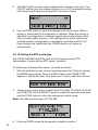
7. At the top of the display it will now read, "SW OPENED AT" and give you
the pressure that the switch opened at.
27
8. Press the "NEXT" option to view when the switch closed, and the dead
band.
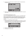
9. Press the "NEW TEST" option to clear the data and perform another test.
10. Press the "DONE" option to end the test and return to the standard
pressure setting.
Important NOTE: The following example uses a normally closed switch.
The basic procedure is still the same for a normally open switch, the display
will just read "OPEN" instead of "CLOSE".
Example:
[P1] ST will return to [P1].
28
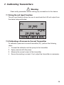
7. Calibrating Transmitters
Warning
Check entity parameters before making any connections to this device.
7.1 Using the mA Input Function
The mA input function allows the user to read back the 4-20 mA output from
the device being calibrated.
7.2 Calibrating a Pressure-to-Current Transmitter
To calibrate a pressure-to-current transmitter (P/I), perform the following
steps:
1. Connect the calibrator and the pump to the transmitter.
2. Apply pressure with the pump.
3. Measure the current output of the transmitter.
4. Ensure the reading is correct. If not, adjust the transmitter as necessary.
29
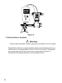
Figure 8.
7.3 Percent Error Function
Warning
Check entity parameters before making any connections to this device.
The calibrator features a unique function which can calculate pressure vs.
milliamp error as a percentage of the 4 to 20 mA loop span. The percent
error mode uses all 3 screens and has a unique menu structure. It
simultaneously displays pressure, mA and percent error.
30
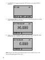
Figure 9.
Example:
Suppose a pressure transmitter under test is 30 psi (2 Bar) Full Scale and
outputs a corresponding 4 to 20 mA signal. The user can program in a 0 to
30 psi pressure span into the calibrator and the calibrator will calculate and
display the deviation or % Error from the expected 4 to 20 mA output. This
eliminates the need for manual calculations and also helps if it becomes
difficult to set an exact pressure with an external pump.
To use the %ERROR function proceed as follows:
1. With the calibrator turned on and operating press the F3 key to activate
the MORE menu option. Now press the F1 key to activate the %ERROR
option.
2. Press the F1 key to select the CONFIG option.
3. The first option is setting the Port, use the select option to scroll through
the port choices, when finished select the NEXT option.
31
4. Use SELECT to toggle through the UNIT options, and select NEXT to
move on.
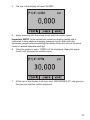
5. Use the cursor keys to set the 100% point of the desired pressure range,
select DONE SET when finished.
6. Again, use the cursor keys to set 0% point and select DONE SET when
finished and the %ERROR mode will be ready to use.
Note: The 0% and 100% point will be saved in non-volatile memory until
they are changed again by the user.
32
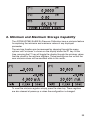
8. Minimum and Maximum Storage Capability
The JOFRA HPC550 Ex/552 Ex Pressure Calibrators have a min/max feature
for capturing the minimum and maximum values of any displayed
parameter.
The min/max function can be accessed by stepping through the menu
options until "min/max" is shown on the display above the F1 key. At this
time, pressing the F1 key will toggle the display through the min/max values
that are stored in the min/max registers. These readings are live so that the
new min/max values will be recorded while in this mode.
To reset the min/max registers simply press the clear key. These registers
are also cleared at power-up or when the configuration is changed.
33
9. Factory Setups
The Calibrator is loaded with five factory setups. These setups are shown
below.
Setup 1: The upper display is set to [P1] mode and the middle is set to mA,
lower is off.
Setup 2: The upper display is set to [P2] mode and the middle is set to mA,
lower is off.
Setup 3: The upper display is set to [P1] mode and the middle is set to
[P2], lower is off.
34
Setup 4: The lower display is set to [P1] switch test, the other displays are
off.
Setup 5: The upper display is set to [P1], the middle display is set to [P2]
and the lower display is set to RTD.
35
10. Custody Transfer / Flow Calibration
Warning
Check entity parameters before making any connections to this device.
The HPC550 Ex/552 Ex is ideal for flow computer calibration. Every
manufacturer of flow computers has a different calibration procedure, but
most call for calibration of three parameters: static pressure, differential
pressure and temperature. To facilitate these measurements recall setup #5
on the HPC550 Ex/552 Ex.
Note: The pressures in the UPPER, and MIDDLE displays can be changed
to [P1], [P2].
1. Connect the calibrator to your static and differential pressures. ([P1],
[P2]) Then connect the RTD sensor to the calibrator.
2. Using the reading of your RTD, static, and differential pressures, make
sure the flow computer has the correct reading. If not, adjust the flow
computer as necessary.
36
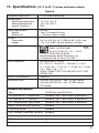
11. Specifications
(18 °C to 28 °C unless otherwise noted.)
General
Instrument Setup Recall
5; last used on power-up
Environmental
Operating Temperature
Storage Temperature
Ingress Protection
-10 °C to +45 °C
-20 °C to +60 °C
IP54
Power Requirements
Battery
Battery Life
6.0 VDC
Four (4) standard AA cells
> 35 hours, typical usage
Physical
Dimensions
Weight
8.3" H x 3.9" W x 2.0" D (200.9 x 99.1 x 50.1 mm)
1 lb. 7 oz. (0.651 kg) with batteries installed
Product Compliance Markings
Ex ia IIB T3 Gb (Ta=–10... +45°C)
KEMA 10 ATEX 0168X
Ex ia IIB T3 Gb (Ta=–10... +45°C)
II 2 G IECEx CSA 10.0013X
Manufactured by Martel Electronics, Inc.,
3 Corporate Park Dr. Derry, NH, USA
0344
Entity Parameters
MEASUREMENT JACKS:
Ui = 30 V; Ii = 80 mA; Pi = 750 mW; Ci = 0 μF;
Li = 0 mH; Uo = 7,14 V; Io = 1,12 mA; Po = 2 mW;
Co = 240 μF; Lo = 1 H
LEMO CONNECTOR: FOR USE WITH HPC-T RTD
PROBE ONLY
EMI/RFI Conformance
EN61326
Connectors/Ports
Pressure (HPC550 Ex) - one, 1/8" BSP female
Pressure (HPC552 Ex) - two, 1/8" BSP female
RTD probe
Included Accessories
Item
HPC550 Ex and HPC552 Ex
1/8" male BSP to ¼" female BSP
Standard 2 pcs. if dual sensor or differential
1/8" male BSP to ¼" male NPT
Standard 2 pcs. if dual sensor or differential
1/8" sealed gasket2 type washer
Standard 2 pcs. if dual sensor or differential
Read + Black test lead and clips
Standard
Hand strap w/clip
Standard
NIST traceable calibration certificate
Standard
User manual
Standard
RS232 cable
Option
Soft case
Option
37
Ranges
Gauge:
70 bar (1000 psi)
200 bar (3000 psi)
350 bar (5000 psi)
700 bar (10,000 psi)
Absolute:
1.1 bar (16 psi)
2 bar (30 psi)
7 bar (100 psi)
20 bar (300 psi)
Differential:
+/- 25 mbar (+/- 0.4 psi)
+/- 70 mbar (+/- 1psi)
+/- 350 mbar (+/- 5psi)
Compound:
+/- 1 bar (-14 to 15 psi)
-1 to 2 bar (-14 to 30 psi)
-0.82 to 7 bar (-12 to 100 psi)
-0.82 to 20 bar (-12 to 300 psi)
-0.82 to 35 bar (-12 to 500 psi)
mA
0 to 24.000 mA
RTD
-40.0°C to 155.0°C
(-40.0°F to 311.0°F)
Engineering Units
psi, bar, mbar, kPa, MPa, kg/cm2, mmH2O @ 4°C,
mmH2O @ 20°C, cmH2O @ 4°C, cmH2O @ 20°C,
inH2O @ 4°C, inH2O @ 20°C, inH2O @ 60°F,
mmHg @ 0°C, inHg @ 0°C
38
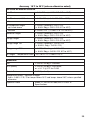
Accuracy 18°C to 28°C (unless otherwise noted)
HPC550 Ex and HPC552 Ex
+/- 25 mbar
Vacuum
+/- 70 mbar, +/- 350 mbar
Vacuum
All compound ranges
not listed above
Vacuum
± 0.1% F.S.
(± 0.15% F.S. 0°C to 45°C)
same as above
± 0.05% F.S. (± 0.1% F.S. 0°C to 45°C)
same as above
± 0.025% Reading ± 0.01% F.S.
(± 0.04% Rdg ± 0.01% F.S. 0°C to 45°C)
± 0.025% F.S. (± 0.05% F.S. 0°C to 45°C)
Absolute ranges
± 0.025% Reading ± 0.01% F.S.
(± 0.04% Rdg ± 0.01% F.S. 0°C to 45°C)
Gauge ranges
± 0.025% Reading ± 0.01% F.S.
(± 0.04% Rdg ± 0.01% F.S. 0°C to 45°C)
Gauge range 10k
± 0,025% Reading + 0.015% F.S.
(± 0.040% Rdg + 0.015% F.S.)
Gauge range 700 bar
± 0.025% Reading ± 0.015% F.S.
(± 0.04% Rdg ± 0.015% F.S. 0°C to 45°C)
All ranges - Temperature Effect -10°C to 0°C is ± 0.005% FS/°C
Electrical
mA
± 0.015% of rdg ± 0.002mA
RTD (ohms)
± 0.015% of rdg ± 0.02 ohms;
or ± 0.1°C @ 0°C for Pt100
Switch-Test
5 VDC (< 1mA)
Temperature Effect - Electrical Ranges
Add ± 0.001% F.S./°C for temps below 18°C and temps above 28°C unless specified
otherwise.
Optional Probe
Meets PT-100 ALPHA 385/EN751 Class "A"
Specifications
39
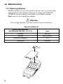
12. Maintenance
12.1 Replacing Batteries
Replace batteries as soon as the battery indicator turns on to avoid false
measurements. If the batteries discharge too deeply the HPC550 Ex/
HPC552 Ex will automatically shut down to avoid battery leakage.
Note: Use only AA size alkaline batteries.
Warning
Only change batteries in an area known to be non-hazardous.
Approved Batteries
40
Battery Manufacturer
(All Batteries Alkaline - A 1.5 V)
Type
Duracell
MN1500
Rayovac
Max Plus 815
Eveready (Energizer)
E91
Panasonic
LR6XWA
12.2 Cleaning the Unit
Warning
To avoid personal injury or damage to the calibrator, use only the specified
replacement parts and do not allow water into the case.
Caution
To avoid damaging the plastic lens and case, do not use solvents or
abrasive cleansers. Clean the calibrator with a soft cloth dampened with
water or water and mild soap.
12.3 Service Center Calibration or Repair
Only qualified service personnel should perform calibration, repairs, or
servicing not covered in this manual. If the calibrator fails, check the
batteries first, and replace them if needed.
Verify that the calibrator is being operated as explained in this manual. If the
calibrator is faulty, send a description of the failure with the calibrator. Be
sure to pack the calibrator securely, using the original shipping container if it
is available.
41
Appendix X
42
43
44
27.72977
27.70759
51.71507
2.03603
inH2O @ 4°C
inH2O @ 20°C
inH2O @ 60°F
mmHg @ 0°C
inHg @ 0°C
0.8144
20.686
11.083
11.092
11.072
281.73
281.24
28.173
28.124
0.0281
0.0028
2.7579
27.579
0.0276
0.4000
70mbar
2.0360
51.715
27.708
27.730
27.681
704.34
703.09
70.434
70.309
0.0703
0.0069
6.8948
68.948
0.0689
1.0000
differential
non-isolated
100
3
10
1
7
200mbar
650mbar
10.180
258.58
138.54
138.65
138.40
3521.7
3515.4
352.17
351.54
0.3515
0.0345
34.474
344.74
0.3447
5.0000
differential
non-isolated
100
10
15
5
7
650mBar
1
350mbar
1
30.540
775.73
415.61
415.95
415.21
10565
10546
1056.5
1054.6
1.0546
0.1034
103.42
1034.2
1.0342
15.000
compound
non-isolated
NA
30
90
15
NA
4
6
32.576
827.44
443.32
443.68
442.89
11269
11249
1126.9
1124.9
1.1249
0.1103
110.32
1103.2
1.1032
16.000
absolute
non-isolated
NA
30
90
16
NA
4
6
1.1
Proof Pressure - maximum allowable pressure without a shift in calibration
Burst Pressure - sensor damaged or destroyed; some risk of personal injury
Static Pressure - Differential units only. Maximum allowed common mode pressure between both ports.
704.336
27.68067
mmH2O @ 20°C
703.089
kg/cm2
mmH2O @ 4°C
0.07030697
MPa
70.3089
0.006894757
kPa
70.4336
6.894757
mbar
cmH2O @ 20°C
68.94757
bar
cmH2O @ 4°C
1
0.06894757
psi
differential
Static Pressure (psi)
Range Type
1
1
Proof Pressure (psi)
non-isolated
3
Sensor Type
0.4
Static Pressure (bar)
Burst Pressure (psi)
70mbar
70mbar
Proof Pressure (bar)
Range (psi)
200mbar
Burst Pressure (bar)
61.081
1551.5
831.23
831.89
830.42
21130
21093
2113.0
2109.3
2.1092
0.2068
206.84
2068.4
2.0684
30.000
compound
absolute
non-isolated
NA
60
90
30
NA
4
6
2
203.60
5171.5
2770.8
2773.0
2768.1
70434
70309
7043.4
7030.9
7.0307
0.6895
689.48
6894.8
6.8948
100.00
compound
absolute
isolated
NA
200
1000
100
NA
13
70
7
610.81
15515
8312.3
8318.9
8304.2
NA
NA
21130
21093
21.092
2.0684
2068.4
20684
20.684
300.00
compound
absolute
isolated
NA
600
2000
300
NA
40
133
20
1018.0
25858
13854
13865
13840
NA
NA
35217
35154
35.153
3.4474
3447.4
34474
34.474
500.00
compound
isolated
NA
1000
2000
500
NA
70
133
35
2036.0
51715
27708
27730
27681
NA
NA
70434
70309
70.307
6.8948
6894.8
68948
68.948
1000.0
gauge
isolated
NA
3000
10000
1000
NA
200
700
70
AMETEK JOFRA™ HPC550 Ex/552 Ex Ranges and Resolutions
25mbar
Range (bar)
200
6108.1
NA
83123
83189
83042
NA
NA
NA
NA
210.92
20.684
20684
NA
206.84
3000.0
gauge
isolated
NA
6000
10000
3000
NA
400
700
350
10180
NA
NA
NA
NA
NA
NA
NA
NA
351.53
34.474
34474
NA
344.74
5000.0
gauge
isolated
NA
10000
10000
5000
NA
700
700
700
20360
NA
NA
NA
NA
NA
NA
NA
NA
703.07
68.948
68948
NA
689.48
10000
gauge
isolated
NA
15000
15000
10000
NA
1000
1000
0200052
Rev H 10/11
127913 00
AMETEK Calibration Instruments
One of the world’s leading manufacturers and developers
of calibration instruments for temperature, pressure and
process signals as well as for temperature sensors both
from a commercial and a technological point of view.
JOFRA Temperature Instruments
Portable precision thermometers. Dry-block and
liquid bath calibrators: 4 series, with more than
25 models and temperature ranges from
-90° to 1205°C/-130° to 2200°F.
JOFRA Pressure Instruments
Convenient electronic systems ranging from
-1 to 1000 bar - multiple choices of pressure ranges,
pumps and accuracies, fully temperature-compensated
for problem-free and accurate field use.
JOFRA Signal Instruments
Process signal measurement and simulation for easy
control loop calibration and measurement tasks - from
handheld field instruments to laboratory reference level
bench top instruments.
JOFRA Marine Instruments
A complete range of calibration equipment for
temperature, pressure and signal, approved for marine
use.
FP Temperature Sensors
A complete range of temperature sensors
for industrial and marine use.
M&G Pressure Testers
Pneumatic floating-ball or hydraulic piston dead weight
testers with accuracies to 0.015% of reading.
M&G Pumps
Pressure generators from small pneumatic “bicycle” style
pumps to hydraulic pumps generating up to 1,000 bar.
www.jofra.com
Headquarters:
AMETEK Denmark A/S
Gydevang 32-34 • 3450 Allerød • Denmark
Tel: +45 4816 8000 • [email protected]
Sales & Service:
Europe, Asia, Africa, Middle East and South America
Sales & Service Offices:
AMETEK Mansfield & Green (North America)
Tel: +1 800 527 9999 • [email protected]
AMETEK Singapore Pte. Ltd. (Singapore)
Tel: +65 6 484 2388 • [email protected]
AMETEK Inc. Beijing Rep. Office (China)
Tel: +86 10 8526 2111 • [email protected]
AMETEK GmbH (Germany)
Tel: +49 2159 9136 510 • [email protected]
Information in this document is subject to change without notice.
©2011, by AMETEK, Inc., www.ametek.com. All rights reserved.
AMETEK Calibration Instruments (UK)
Tel: +44 (0) 1243 833 302 • [email protected]