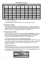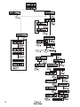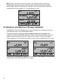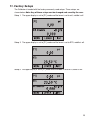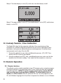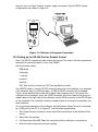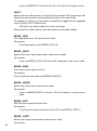
1
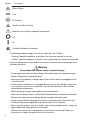
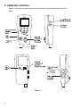
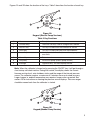
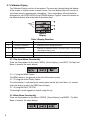
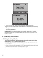
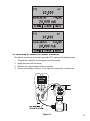
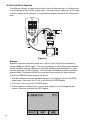
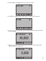
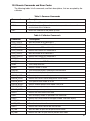
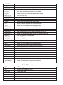
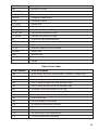
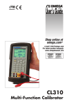
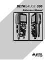
BETAGAUGE 330
Reference Manual
BETAGauge 330
Reference Manual
1. Introduction . . . . . . . . . . . . . . . . . . . . . . . . . . . . . . . . . . . . . . . . . . . .1
1.1 Contacting Martel / Beta . . . . . . . . . . . . . . . . . . . . . . . . . . . . . . . . . . . .1
1.2 Standard Equipment . . . . . . . . . . . . . . . . . . . . . . . . . . . . . . . . . . . . . . .1
1.3 Safety Information . . . . . . . . . . . . . . . . . . . . . . . . . . . . . . . . . . . . . . . . .1
2. Calibrator Interface . . . . . . . . . . . . . . . . . . . . . . . . . . . . . . . . . . . . . .4
2.1 Calibrator Display . . . . . . . . . . . . . . . . . . . . . . . . . . . . . . . . . . . . . . . . .6
2.2 Using the Backlight . . . . . . . . . . . . . . . . . . . . . . . . . . . . . . . . . . . . . . . .8
2.3 Using the Zero Function . . . . . . . . . . . . . . . . . . . . . . . . . . . . . . . . . . . .8
2.4 Other Menu Controlled Functions . . . . . . . . . . . . . . . . . . . . . . . . . . . . .9
3. Initial Setup and Basic Pressure Generation . . . . . . . . . . . . . . . . . .12
4. Measuring Pressure . . . . . . . . . . . . . . . . . . . . . . . . . . . . . . . . . . . . .14
4.1 Media Compatibility . . . . . . . . . . . . . . . . . . . . . . . . . . . . . . . . . . . . . . .14
4.2 Measuring Pressure with External Modules . . . . . . . . . . . . . . . . . . . . .14
5. Measuring Current . . . . . . . . . . . . . . . . . . . . . . . . . . . . . . . . . . . . . .15
6. Measuring Voltage . . . . . . . . . . . . . . . . . . . . . . . . . . . . . . . . . . . . . .17
7. Measuring Temperature with an RTD
. . . . . . . . . . . . . . . . . . . . . . .17
8. Performing a Pressure Switch Test . . . . . . . . . . . . . . . . . . . . . . . . .18
9. Calibrating Transmitters . . . . . . . . . . . . . . . . . . . . . . . . . . . . . . . . .20
9.1 Using the mA Input Function . . . . . . . . . . . . . . . . . . . . . . . . . . . . . . . .20
9.2 Calibrating a Pressure-to-Current Transmitter . . . . . . . . . . . . . . . . . . . .21
9.3 Percent Error Function . . . . . . . . . . . . . . . . . . . . . . . . . . . . . . . . . . . . .22
10. Minimum and Maximum Storage Capability . . . . . . . . . . . . . . . . . .24
11. Factory Setups . . . . . . . . . . . . . . . . . . . . . . . . . . . . . . . . . . . . . . . .25
12. Custody Transfer / Flow Calibration
. . . . . . . . . . . . . . . . . . . . . . .26
13. Remote Operation . . . . . . . . . . . . . . . . . . . . . . . . . . . . . . . . . . . . .26
13.1 Remote Interface . . . . . . . . . . . . . . . . . . . . . . . . . . . . . . . . . . . . . . .26
13.2 Setting up the RS-232 Port for Remote Control . . . . . . . . . . . . . . . . .27
13.3 Changing Between Remote and Local Operation . . . . . . . . . . . . . . . .28
13.4 Using Commands . . . . . . . . . . . . . . . . . . . . . . . . . . . . . . . . . . . . . . .28
13.5 Remote Commands and Error Codes . . . . . . . . . . . . . . . . . . . . . . . .31
13.6 Entering Commands . . . . . . . . . . . . . . . . . . . . . . . . . . . . . . . . . . . . .34
14. Specifications . . . . . . . . . . . . . . . . . . . . . . . . . . . . . . . . . . . . . . . . .42
15. Warranty
. . . . . . . . . . . . . . . . . . . . . . . . . . . . . . . . . . . . . . . . . . . . .43
16. Maintenance . . . . . . . . . . . . . . . . . . . . . . . . . . . . . . . . . . . . . . . . . .43
16.1 Replacing Batteries . . . . . . . . . . . . . . . . . . . . . . . . . . . . . . . . . . . . . .43
16.2 Cleaning the Unit . . . . . . . . . . . . . . . . . . . . . . . . . . . . . . . . . . . . . . . .43
16.3 Valve Cleaning Procedure . . . . . . . . . . . . . . . . . . . . . . . . . . . . . . . . . .43
16.4 Service Center Calibration or Repair . . . . . . . . . . . . . . . . . . . . . . . . .44
1. Introduction
The BetaGauge 330 is designed to be a simple to use yet very versatile pressure
calibrator. Its internal pressure sensor combined with an innovative electrically powered
pump along with inputs for mA, voltage, switch contacts and an RTD probe allow the 330
to calibrate virtually any pressure device. The model 330-300 uses a manual pump to
reach higher pressures up to 300 psi. An external pressure module option allows an even
wider range of pressure calibration options including absolute and differential.
1.1 Customer Service
Corporate Office:
www.martelcorp.com
e-mail: [email protected]
Tel: (603) 434-1433 800-821-0023 Fax: (603) 434-1653
Martel Electronics
3 Corporate Park Dr.
Derry, NH 03038
1.2 Standard Equipment
Check to see if your calibrator is complete. It should include: BetaGauge 330 Calibrator,
instruction manual, test leads, calibration hose kit with fittings, carrying case, calibration
certificate with data.
1.3 Safety information
Symbols Used
The following table lists the International Electrical Symbols. Some or all of these symbols
may be used on the instrument or in this manual.
Symbol
Description
AC (Alternating Current)
AC-DC
Battery
CE Complies with European Union Directives
DC
Double Insulated
1
Symbol
Description
Electric Shock
Fuse
PE Ground
Hot Surface (Burn Hazard)
Read the User’s Manual (Important Information)
Off
On
Canadian Standards Association
The following definitions apply to the terms “Warning” and “Caution”.
• “Warning” identifies conditions and actions that may pose hazards to the user.
• “Caution” identifies conditions and actions that may damage the instrument being used.
Use the calibrator only as specified in this manual, otherwise injury and damage to the
calibrator may occur.
Warning
To avoid possible electric shock or personal injury:
• Do not apply more than the rated voltage. See specifications for supported ranges.
• Follow all equipment safety procedures.
• Never touch the probe to a voltage source when the test leads are plugged into the
current terminals.
• Do not use the calibrator if it is damaged. Before you use the calibrator, inspect the
case. Look for cracks or missing plastic. Pay particular attention to the insulation
surrounding the connectors.
• Select the proper function and range for your measurement.
• Make sure the battery cover is closed and latched before you operate the calibrator.
• Remove test leads from the calibrator before you open the battery door.
• Inspect the test leads for damaged insulation or exposed metal. Check test leads
continuity. Replace damaged test leads before you use the calibrator.
• When using the probes, keep your fingers away from the probe contacts. Keep your
fingers behind the finger guards on the probes.
• Connect the common test lead before you connect the live test lead. When you
disconnect test leads, disconnect the live test lead first.
2
• Do not use the calibrator if it operates abnormally. Protection may be impaired. When in
doubt, have the calibrator serviced.
• Do not operate the calibrator around explosive gas, vapor, or dust.
• When measuring pressure, make sure the process pressure line is shut off and
depressurized before you connect it or disconnect it from the pressure module.
• Disconnect test leads before changing to another measure or source function.
• When servicing the calibrator, use only specified replacement parts.
• To avoid false readings, which could lead to possible electric shock or personal injury,
replace the battery as soon as the battery indicator appears.
Caution
To avoid possible damage to calibrator or to equipment under test:
• Use the proper jacks, function, and range for your measurement or sourcing application.
3
2. Calibrator Interface
Figure 1 shows the location of the pressure controls, connection port and electrical
inputs.
Figure 1
4
Figures 2A and 2B show the location of the keys. Table 2 describes the function of each key.
Figure 2A
Keypad (Electric Pump Versions)
Table 2 Key Functions
No.
Name
Description
1
Function Keys
These are soft keys used to configure the calibrator
2
ON/OFF Key
This key is used to turn the calibrator on and off
3
ZERO Key
This key is used to zero pressure measurements
4
Arrow Keys
Used to control mA source/sim. and to set pump and %
error limits
5
Home Key
Return to main menu screen
6
Pump Key
Push to run pump (Electric pump version)
6
Backlight
Figure 2B only - for manual pump version
Note: When the calibrator is turned on by pressing the ON/OFF key, it will go through a
short startup self-check routine. During that routine, the display shows the current
firmware revision level, auto shutdown status and the range of the internal pressure
sensor. The calibrator requires a maximum of 5 minutes warm-up to rated accuracy.
Large changes in ambient temperature may require a longer warm-up period. See
section 2.3 for instructions on zeroing the pressure sensor displays. Pressure ranges
should be zeroed each time the calibrator is started.
Figure 2B
Keypad (Manual Pump Version)
5
2.1 Calibrator Display
The Calibrator Display consists of two regions: The menu bar (located along the bottom
of the screen) is used to access a menu system. The main display (the rest) consists of
up to three process measurement sub-regions. These sub-regions will henceforth be
referred to as the UPPER, MIDDLE and LOWER displays. Figure 3 shows the location of
the different display fields while table 3 describes them.
Figure 3
Display
Table 3 Display Functions
No.
Name
Description
1
Primary Parameters
Indicates what is being measured.
2
Span Indicator
Indicates the percent of the 4 to 20 mA span. (For mA and
mA Loop functions only)
3
Pressure Units
Indicates one of 15 pressure units available for display.
4
Units
Indicates the unit of measure for the display.
2.1.1 Top Level Menu Functionality
There are three options for this menu: MENU, {Active Display}, and LIGHT. The Top Level
Menu is home for the menu display.
2.1.1.1 Using the MENU Option
The MENU option is the gateway to the rest of the menu system.
2.1.1.2 Using the Active Display Option
The active display is indicated by the center option on the Top Level Menu. It is used to
select the display to which the ZERO key will apply.
2.1.1.3 Using the LIGHT OPTION
The backlight can be toggled on and off using this key.
2.1.2 Main Menu Functionality
There are three options on the Menu, CONFIG, {Active Display} and MORE. The Main
Menu is home for the menu display.
6
2.1.2.1 Setting the Active Display
The active display is indicated by the center option on the Main Menu, pressing the F2
key will toggle the active display.
2.1.2.2 Setting Active Display Parameters
To set the parameters of the active display use the CONFIG option to get to the Display
Configuration Menu.
Here the SELECT option will toggle through the choices for each parameter. The first
parameter is MODE. Since voltage, current and switch test modes all use the same
jacks, two of these functions cannot be used concurrently. The ability to select certain
functions is limited based on what is already selected in another display. The NEXT
option is used to change to the second parameter. Only RTD and Pressure modes have
a second parameter, RTDs can be read in Celsius or Fahrenheit and Pressures can be
read in 11 engineering units.
With a single display the following modes are available:
P[1] = Pressure internal sensor.
[EXT] = Pressure with external pressure module.
P[1] ST = Switch Test with left side sensor.
[EXT] ST = Switch Test with external pressure module.
Note: mA functions are only available on the Lower Display.
mA measure = Milliamps measure without loop power.
mA w/24V = Milliamps measure with loop power.
mA source = Milliamps source.
mA sim = Milliamps simulate using an external supply from the UUT.
VOLTS = Voltage Measure.
RTD = RTD Temperature Measurement (if a probe is connected).
The following table shows which functions are available concurrently.
An X in a column indicates that the mode in the active display will not be available for
selection if the mode in that row is in use in any other display.
7
Table 4 Mode Concurrency
CURRENT DISPLAY
OTHER DISPLAYS
P[1]
[EXT]
P[1]
ST
[EXT]
ST
mA
mA
Loop
Volts
P[1]ST
X
X
X
X
X
[EXT]ST
X
X
X
X
X
mA
X
X
X
X
mA Loop
X
X
X
Volts
X
X
X
RTD
P[1]
[EXT]
X
X
RTD
X = Not a valid mode
2.1.1.3 Accessing Other Menus
Use the MORE option on the Main Menu to access the other menu functions.
2.2 Using the Backlight
The backlight is controlled by the LIGHT softkey on the main menu on the models with
electric pump. The 330-300 psi has a dedicated backlight key. It toggles on and off when
the key is pressed; this is one of the few functions that cannot be controlled by the serial
interface. There are no user configuration settings for the backlight.
2.3 Using the Zero Function
When the ZERO KEY is pressed, the calibrator will zero the active display if a pressure
mode is selected, and the pressure is within the zero limit. The zero limits are within 10%
of the full scale range of the selected sensor. If the display indicates “OL,” the zero
function will not operate.” Note: The ZERO KEY is only used for pressure.
2.3.1 Internal Sensor and Pressure Module (non-absolute)
When a sensor or module is selected on the active display and the ZERO KEY is pressed
the calibrator subtracts the current reading from the output. The zero limits are within 10%
of the full scale range of the selected sensor. If the display indicates “OL,” the zero
function will not operate.
2.3.2 Absolute Pressure
When an absolute pressure range is selected on the active display and the ZERO KEY is
pressed the calibrator prompts the user to enter the barometric reference pressure. This
is done using the arrow keys (F2 and F3 Keys). The sensor port should be open (vented)
to atmosphere while performing this procedure.
8
2.4 Other Menu Controlled Functions
There are 12 ‘sub-main’ menus that can be accessed through the MORE option of the
Main Menu. A ‘sub-main’ menu contains three options. The first option is unique to the
function. The second and third options of a ‘sub-main’ menu are always the same. The
NEXT option leads to the next ‘sub-main’ menu and the DONE option returns home . For
the last ‘sub-main’ menu the NEXT option wraps around to home. See Figure 4 for a
detailed mapping of the menu structure.
A note on naming convention:
If a ‘sub-main’ menu has subordinate menus, it will henceforth be referred to as
{function} Main Menu. E.g. the display contrast sub-main menu will be called the
Contrast Main Menu. If not it will be called the {function} menu.
2.4.1 Setting the Contrast
From the Contrast Main Menu choose the CONTRAST option to access the Contrast
Adjustment Menu.
Use the F2, F3 keys to adjust the display contrast to the desired level and then use the
CONTRAST DONE option to return home.
2.4.2 Locking and Unlocking Configurations
Use the LOCK CFG or UNLOCK CFG option of the Configuration Lock Menu to lock or
unlock the display configuration.
When the LOCK CFG option is chosen the menu display returns home and the CONFIG
option on the Main Menu indicates that it is locked. Also all menus are locked out with
the exception of the Min Max Menu, Contrast Adjustment menus and the Configuration
Lock Menu. When the UNLOCK CFG option is chosen the configuration is unlocked and
the menu display continues to the next sub-main menu.
2.4.3 Saving and Recalling Setups
The calibrator will automatically save the current set-up for recall at power-up.
Additionally 5 set-ups can be accessed through the SETUPS menu. Select the SETUPS
option from the Setups Main Menu.
Choose SAVE to save a set-up , RECALL to recall the set-up, or DONE to do nothing and
return home.
9
10
Figure 4
Menu Map
If SAVE or RECALL is selected use the arrow keys to select the set-up location. Then use
the save option to store the current set-up into the selected location or the recall option to
recall the set-up stored in the selected location. The display menu will automatically go
home.
2.4.4 Setting AutoShut-off Parameters
The calibrator can be set to automatically shut-off after a selected number of minutes; this
function can also be disabled. To set the auto shut off parameters select the AUTO OFF
option on the Auto Shut Off Main Menu.
Use the F2, F3 keys to select the number of minutes before the calibrator turns off or
disable auto shut-off by scrolling all the way down.
Use the AUTO OFF DONE option to set the parameters and return home. The auto shut
off time is reset whenever a key is pressed.
2.4.5 Activating and Deactivating a Display
Use the DISPLAY option on the Display Selection Main Menu to access the Display
Activation Menu.
The {display} option can be used to select which display to act upon. The ON/OFF
option turns the selected display on or off. The selected display and current on/off state
are displayed in the lower display.
Use the DONE option to save the changes and return home. When a display is
deactivated its configuration is retained. When the display is activated its configuration is
11
checked against the configurations of the other currently active displays, if the
configurations are in conflict the recalled display’s configuration is modified to avoid the
conflict. If all three displays are deactivated the LOWER display will come on
automatically
2.4.6 Setting the RTD probe type
Use the PROBE TYPE option of the RTD Probe Type main menu to access the RTD
Probe selection menu.
There are four probe types to select from P100-385, P100-392, P100-JIS and CUSTOM.
Use the SELECT option to select the desired probe type and the DONE option to store
the change and return home.
Note: The default probe type is PT100-385.
2.4.7 Damping
Damping can be turned ON or OFF using the Damping menu selection. When damping
is ON, the calibrator displays an running average reading of ten measurements. The
calibrator makes approximately 3 readings per second.
2.4.8 Pump Limits
To prevent overpressure of sensitive devices the maximum pressure (pump limit) can be
set. When in this mode use the arrow keys to set the maximum pressure.
2.4.9 HART™ Resistor
An internal 250 ohm HART Resistor can be enabled when the BetaGauge 330 is operated
in the “mA Measure-24V” mode. This allows a HART Communicator to be connected
across the mA terminals and eliminates the need for adding an external resistor.
Note: When the HART resistor is on the maximum load driving capacity is 750 ohms.
3. Initial Setup and Basic Pressure Generation
1. The BetaGauge 330 is supplied with a special low volume calibration hose kit to
facilitate faster pumping to pressure and quick pressure stabilization. the kit also
comes with the required “quick-fit” hose connectors and a BSP adapter for non-NPT
applications. It is highly recommended that this type of hose is used to achieve the
best performance of the product. Once the fittings are installed and the calibrator is
connected to the unit under test (UUT) the calibrator is ready for use. Figure 5 shows a
typical setup.
12
2. Before generating pressure make sure you have the 330 configured for your
application. If needed review section 2 of the manual again to select the proper
configuration.
3. Make sure that the pressure vacuum knob is set for the function you want to perform
(+ for pressure and – for vacuum).
4. Close the vent knob.
5. Press the pump key (or manually stroke the pump on the 300psi/20 bar model) and
watch the pressure (or vacuum) increase until you reach the desired pressure.
Note: On the electric pump version the motor speed will start slowly when
pressure is low (<15psi) to allow better control at low pressures.
6. Use the fine adjustment vernier to fine tune the pressure/vacuum reading as needed.
7. To reduce or bleed off the pressure entirely slowly rotate the vent knob to the open
position. Doing this step carefully will allow you to control the pressure bleed rate to a
high degree and will facilitate taking down-scale pressure readings.
3.1 Electric Pump Considerations
The BetaGauge 330-30 and 330-150 incorporate a small, lightweight, battery powered
pneumatic pump that allows the user, in the case of the 330-150 to build relatively high
pressure up to 150psi (10Bar) quickly and with good control. Because the pump has an
upper pressure generation limit of 160psi there may be atmospheric conditions where it
cannot achieve the full scale pressure of 150psi. High altitude use (about 3000 ft or 1000
meters) or use at cold temperatures may limit the pump to about 135psi (9 Bar). In these
cases the vernier adjustment can be used to generate the additional pressure needed if
full scale pressure must be generated.
In these situations the user should begin the calibration with the vernier in the full counter
clockwise position and then when the electric pump reaches its limit turn the vernier in
the clockwise direction to raise the pressure and to set the desired reading.
Figure 5
13
4. Measuring Pressure
To measure pressure, connect the calibrator using an appropriate fitting. Choose a
pressure setting for the display being used. The calibrator is equipped with one internal
sensors and many optional external sensors (EPMs) are available. Be sure to choose the
sensor based on working pressures and accuracy.
Note:
Pressure sensors may be damaged and/or personnel injury may occur due to improper
application of pressure. Please refer to the table of ranges and resolutions at the back of
this manual for information on overpressure and burst pressure ratings. Vacuum should
not be applied to any gauge pressure sensor. The calibrator display will indicate “OL”
when an inappropriate pressure is applied. If “OL” is observed on any pressure display,
the pressure should be reduced or vented immediately to prevent damage or possible
personnel injury. “OL” is displayed when the pressure exceeds 110% of the nominal range
of the sensor or when a vacuum in excess of 2 PSI is applied on gauge range sensors.
Use the (ZERO) key to zero the pressure sensor when vented to atmospheric pressure.
Important NOTE: To protect sensor integrity and prevent damage to the sensor, the
calibrator will display OL [overload] when the applied pressure exceeds 110% of the full
scale calibrated range of the sensor.
Important NOTE: To ensure accuracy of the calibrator it is critical to zero the calibrator
before a device is calibrated. See section 2.3.
4.1 Media Compatibility
The BetaGauge 330 feature a unique user accessible valve cleaning port to facilitate
servicing the pump. Section 16.3 shows how to clean these valves. Even though
servicing the pump is easy, care should be taken to only expose the calibrator to clean,
dry gases.
4.2 Measuring Pressure with External Modules
The calibrator provides a digital interface to External Pressure Modules. These modules
are available in various ranges and types including gauge, vacuum, differential and
absolute. The modules work seamlessly with the calibrator. Simply plug them into the
interface and select [EXT] (external sensor). Since the interface between the calibrator
and the module is digital all the accuracy and display resolution is derived from the
module.
14
Figure 6
5. Measuring and Generating Current (4 to 20 mA)
1. To measure current use the input terminals in the front of the calibrator. Select the mA
function on the lower display. Current is measured in mA and percentage of range.
The range on the calibrator is set to 0% at 4 mA and 100% at 20 mA.
For example:
If the current measured is displayed as 75% then the mA value is 16 mA.
Note: The display will indicate “OL” when the measured current exceeds the nominal
range of current measurement (24 milliAmps).
2. To source current the same connections are used. From the configuration screen
select mA source or mA Sim-2W.
3. Note that this function can only be done on the LOWER screen. Also in the source
mode the calibrator will generate 0 to 24 mA using its own internal 24 volt supply
whereas in the simulate mode the calibrator acts as a 2 wire transmitter and requires
an external 24 volt supply.
4. Pressing any of the arrow keys will start the output mode and allow you to use the
arrow keys to adjust the mA output. The function keys can also be used to step the
output in either 25% steps (4, 8, 12, 16, 20 mA) or 0% (4 mA) and 100% (20 mA).
5. While in the mA output mode if the loop is opened or the compliance is exceeded the
unit will flash “OL” .
15
Figure 7-1
Figure 7-2
Figure 7-3
Figure 7-4
16
6. Measuring Voltage
To measure voltage use the input terminals in the front of the calibrator. Select the Volts
function on one of the displays. The calibrator can measure up to 30V.
Note: The display will indicate “OL” when the measured voltage exceeds the nominal
range of voltage measurement (30 V).
Figure 8
7. Measuring Temperature with an RTD
To measure temperature using an RTD probe you must select the RTD function on one of
the displays. Make sure the proper probe type is selected. There are 4 probe types
supported, P100-385, P100-392, P100-JIS and CUSTOM. The standard probe has a 10”
insertion depth with a 1/4” diameter stainless steel sheath.
Note: The factory default type is PT100-385 so if the 330 is being used with the Martel
Model LPT100A probe you do not have to set the probe type. Simply plug the probe into
the 330 and configure the display to read temperature.
Note: The display will indicate “OL” when the measured temperature is outside the
nominal measurement range of the RTD function (below -40°C or above 150°C).
If a custom probe is being used, the entering of R0 and coefficients is handled through
the serial interface (see section 13).
17
Figure 9
8. Performing a Pressure Switch Test
Figure 10
To perform a switch test, follow these steps:
1. Change the setup to Setup 4 (default switch test).
Setup 4: The upper display is set to [P1] ST, all other displays are off.
Important NOTE: The pressure Switch Test can be performed with the following
functions[P1] ST, or EXT ST.
2. Connect the calibrator to the switch using the pressure switch terminals. The polarity
of the terminals does not matter. Then connect the pump to the calibrator and the
pressure switch.
18
3. Make sure the vent on the pump is open. Zero the calibrator if necessary. Close the
vent after zeroing the calibrator.
4. The top of the display will read “CLOSE”.
5. Apply pressure with the pump slowly until the switch opens.
Important NOTE: In the switch test mode the display update rate is increased to help
capture changing pressure inputs. Even with this enhanced sample rate pressurizing the
device under test should be done slowly to ensure accurate readings.
6. Once the switch is open, “OPEN” will be displayed, bleed the pump slowly until the
pressure switch closes.
7. At the top of the display it will now read, “SW OPENED AT” and give you the
pressure that the switch opened at.
8. Press the “NEXT” option to view when the switch closed, and the dead band.
19
9. Press the “NEW TEST” option to clear the data and perform another test.
10. Press the “DONE” option to end the test and return to the standard pressure setting.
Example:
[P1] ST will return to [P1].
Important NOTE: The previous example uses a normally closed switch. The basic
procedure is still the same for a normally open switch, the display will just read “OPEN”
instead of “CLOSE”.
9. Calibrating Transmitters
9.1 Using the mA Input Function
The mA input function allows the user to read back the 4-20 mA output from the device
being calibrated. This can be done in one of two ways.
1) Passively – Where the device under test directly generates 4-20 mA and can be read
by the calibrator.
2) Actively – Where the calibrator supplies 24 VDC loop power to the device under test to
power the device while reading the resulting 4-20 mA signal.
20
9.2 Calibrating a Pressure-to-Current Transmitter
To calibrate a pressure-to-current transmitter (P/I), perform the following steps:
1. Connect the calibrator and the pump to the transmitter.
2. Apply pressure with the pump.
3. Measure the current output of the transmitter.
4. Ensure the reading is correct. If not, adjust the transmitter as necessary.
Figure 11.
21
9.3 Percent Error Function
The calibrator features a unique function which can calculate pressure vs. milliamp error
as a percentage of the 4 to 20 mA loop span. The percent error mode uses all 3 screens
and has a unique menu structure. It simultaneously displays pressure, mA and percent
error.
Figure 12.
Example:
Suppose a pressure transmitter under test is 30 psi (2 Bar) Full Scale and outputs a
corresponding 4 to 20 mA signal. The user can program in a 0 to 30 psi pressure span
into the calibrator and the calibrator will calculate and display the deviation or % Error
from the expected 4 to 20 mA output. This eliminates the need for manual calculations
and also helps if it becomes difficult to set an exact pressure with an external pump.
To use the %ERROR function proceed as follows:
1. With the calibrator turned on and operating press the F3 key to activate the MORE
menu option. Now press the F1 key to activate the %ERROR option.
2. Press the F1 key to select the CONFIG option.
3. The first option is setting the Port, use the select option to scroll through the port
choices, when finished select the NEXT option.
22
4. LOOP POWER can be toggled on/off, select NEXT when done.
5. Use SELECT to toggle through the UNIT options, and select NEXT to move on.
6. Use the arrow keys to set the 100% point of the desired pressure range, select DONE
SET when finished.
7. Again, use the arrows to set 0% point and select DONE SET when finished and the
%ERROR mode will be ready to use.
23
Note: The 0% and 100% point will be saved in non-volatile memory until they are
changed again by the user for the internal sensors, and external pressure modules.
When using an external module the 0% and 100% are set to low and full scale of the
module until the user changes it, or if it was previously saved.
10. Minimum and Maximum Storage Capability
The 300 Series Pressure Calibrators have a min/max feature for capturing the minimum
and maximum values of any displayed parameter.
The min/max function can be accessed by stepping through the menu options until
“min/max” is shown on the display above the F1 key. At this time, pressing the F1 key will
toggle the display through the min/max values that are stored in the min/max registers.
These readings are live so that the new min/max values will be recorded while in this mode.
To reset the min/max registers simply press the clear key. These registers are also cleared
at power-up or when the configuration is changed.
24
11. Factory Setups
The Calibrator is loaded with five factory commonly used setups. These setups are
shown below. Note: Any of these setups can be changed and saved by the user.
Setup 1: The upper display is set to [P1] mode and the lower is set to mA, middle is off.
Setup 2: The upper display is set to [P1] mode and the lower is set to RTD, middle is off.
Setup 3: The upper display is set to [P1] mode and the middle is set to RTD, lower is mA.
25
Setup 4: The lower display is set to [P1] switch test, the other displays are off.
Setup 5: The upper display is set to [P1], the middle display is set to [EXT] and the lower
display is set to RTD.
12. Custody Transfer / Flow Calibration
The Model 330 is ideal for flow computer calibration. Every manufacturer of flow
computers has a different calibration procedure, but most call for calibration of three
parameters: static pressure, differential pressure and temperature. To facilitate these
measurements recall setup #5 on the 330.
1. Connect the calibrator to your static and differential pressures. ([P1], EXT) Then
connect the RTD sensor to the calibrator.
2. Using the reading of your RTD, static, and differential pressures make sure the flow
computer has the correct reading. If not, adjust the flow computer as necessary.
13. Remote Operation
13.1 Remote Interface
The calibrator can be remotely controlled using a PC terminal, or by a computer program
running the calibrator in an automated system. It uses an RS-232 serial port connection
for remote operation. NOTE: To use the remote control option a custom RS-232
cable must be purchased from Martel (LEM232). To contact Martel refer to
Section 1.1 of this manual. With this connection the user can write programs on the
PC, with Windows languages like Visual Basic to operate the calibrator, or use a Windows
26
terminal, such as Hyper Terminal, to enter single commands. Typical RS-232 remote
configurations are shown in Figure 13.
Figure 13. Calibrator-to-Computer Connection
13.2 Setting up the RS-232 Port for Remote Control
Note: The RS-232 connection cable should not exceed 15m unless the load capacitance
measured at connection points is less than 2500pF.
Serial parameter values:
9600 baud
8 data bits
1 stop bit
no parity
Xon/Xoff
EOL (End of Line) character or CR (Carriage Return) or both
The LEM232 cable is used for RS-232 communications from the calibrator to a computer.
If the computer only has USB type ports, a USB to RS-232 converter will be needed.
These can be obtained from most office supply and computer stores. To connect the
calibrator to the computer, attach the LEMO connector end of the cable to the pressure
module port on the right side of the calibrator and the DB-9 connector to the RS-232 port
on the computer. The calibrator should be turned off prior to making the connection and
then turned on.
To set up remote operation of the calibrator on the Windows Hyper Terminal, connected
to a COM port on the PC as in Figure 23, use the following procedure:
1. Start Hyper Terminal (located in Accessories/Communications of the Windows Start
menu)
2. Select New Connection.
3. For Name enter Beta 330. Select the serial port that the calibrator is connected to.
4. Enter the above information for port settings.
27
5. Select ASCII setup from File/Properties/Settings and mark these choices:
Echo typed characters locally
Wrap lines that exceed terminal width
6. Select Ok
7. To see if the port works enter *IDN?. This command will return information on the
calibrator.
13.3 Changing Between Remote and Local Operation
There are three modes of operation of the calibrator, Local, Remote, and Remote with
Lockout. Local mode is the default mode. Commands may be entered using the keypad
on the calibrator or using a computer. In Remote mode the keypad is disabled, and
commands may only be entered using a computer, but choosing [GO TO LOCAL] from
the menu on the calibrator display will restore keypad operation. In Remote with Lockout,
the keypad can not be used at all. To switch modes proceed as follows:
1. To enable Remote mode, type in the serial command REMOTE at the computer
terminal.
2. To enable Remote with Lockout, type in “REMOTE LOCKOUT” in either order.
3. To switch back to local operation enter LOCAL at the terminal. This command also
turns off LOCKOUT if it was on. For more information on commands refer to the
Remote Commands section.
13.4 Using Commands
13.4.1 Command types
Refer to the Section 10.5 on Remote Commands for all available commands.
The calibrator may be controlled using commands and queries. All commands may be
entered using upper or lower case. The commands are divided into the following
categories:
Calibrator Commands
Only the calibrator uses these commands. For example
VAL?
asks for the values displayed on the calibrator display.
Common Commands
Standard commands used by most devices. These commands always begin with an “*”.
For example
*IDN?
tells the calibrator to return its identification.
Query Commands
Commands that ask for information, they always end with a “?”. For example:
FUNC?
Returns the current modes of the calibrator displays.
28
Compound Commands
Commands that contain more than one command on one line. For example;
RTD_TYPE PT385_100;RTD_TYPE?
Sets the calibrator to RTD type PT385_100 and queries it to verify. It will return:
PT385_100
13.4.2 Character Processing
The data entered into the calibrator is processed as follows:
• ASCII characters are discarded if their decimal equivalent is less than 32 (space),
except 10 (LF) and 13 (CR):
• Data is taken as 7-bit ASCII
• The most significant data bit is ignored.
• Upper or lower case is acceptable.
13.4.3 Response Data Types
The data returned by the calibrator can be divided into four types:
Integer
For most computers and controllers they are decimal numbers ranging from -32768 to
32768. For example:
FAULT? could return 110
Refer to the Error Codes table (Table 8) for more information on error codes.
Floating
Floating numbers have up to 15 significant figures and exponents. For example:
CPRT_COEFA? returns 3.908300E-03
Character Response Data (CRD)
Data returned as keywords. For example:
RTD_TYPE? returns PT385_100
Indefinite ASCII (IAD)
Any ASCII characters followed by a terminator. For example:
*IDN? returns BETA, 330, 250, 1.00
29
13.4.4 Calibrator Status
Error Queue
If an error occurs due to invalid input or buffer overflow, its error code is sent to the error
queue. The error code can be read from the queue with the command FAULT?. The error
queue holds 15 error codes. When it is empty, FAULT? returns 0. The error queue is
cleared when power is reset or when the clear command *CLS is entered.
Input Buffer
Calibrator stores all received data in the input buffer. The buffer holds 250 characters. The
characters are processed on a first in, first out basis.
30
13.5 Remote Commands and Error Codes
The following tables list all commands, and their descriptions, that are accepted by the
calibrator.
Table 5: Common Commands
Command
Description
*CLS
(Clear status.) Clears the error queue.
*IDN?
Identification query. Returns the manufacturer, model number, and firmware
revision level of the Calibrator.
*RST
Resets the calibrator to the power up state.
Table 6: Calibrator Commands
Command
Description
CPRT_COEFA
Sets the custom RTD coefficient A
CPRT_COEFA?
Returns the custom RTD coefficient A
CPRT_COEFB
Sets the custom RTD coefficient B
CPRT_COEFB?
Returns the custom RTD coefficient B
CPRT_COEFC
Sets the custom RTD coefficient C
CPRT_COEFC?
Returns the custom RTD coefficient C
CPRT_R0
Sets the custom RTD R0 resistance
CPRT_R0?
Returns the custom RTD R0 resistance
DAMP
Turns Damp on or off.
DAMP?
Returns if DAMP is on/off
DISPLAY
Turns on/off the displays specified in the command
DISPLAY?
Returns which displays are on/off
ERROR_LOOP
Turns loop power on or off in percent error mode
ERROR_LOOP?
Returns the current state of loop power in error mode
ERROR_MODE
Turns percent error mode on or off
ERROR_MODE?
Returns whether percent error mode is on or off
ERROR_PORT
Set the pressure port for percent error mode
ERROR_PORT?
Returns the pressure port for percent error mode
FAULT?
Returns the most recent error code
FUNC
Sets the display mode as specified in the command
FUNC?
Returns the current mode of the upper, middle, and lower display
HART_ON
Turns the hart resistor on.
HART_OFF
Turns the hart resistor off.
HART?
Returns the current state of the Hart resistor.
HI_ERR
Sets the 100% of span limit for percent error mode
HI_ERR?
Returns the 100% of span limit for percent error mode
31
IO_STATE
Set the calibrator's mA state.
IO_STATE?
Return the calibrator's mA state.
LOCAL
Returns user to manual operation of the calibrator
LOCKOUT
Locks out the keypad of the calibrator in remote operation
LO_ERR
Sets the 0% of span limit for percent error mode
LO_ERR
Returns the 0% of span limit for percent error mode
MOTOR_ON
Turns the motor on.
MOTOR_OFF
Turns the motor off.
MOTOR?
Returns the current state of the Hart resistor
OHMS?
Returns ohms value measured from the RTD
OUT
Set the calibrator to output the requested current.
OUT?
Returns the value of the current being simulated.
PRES_UNIT
Set the pressure unit for the indicated display
PRES_UNIT?
Returns the pressure from the indicated display
PUMP_LIMIT
Sets the approximate value at which the pump will turn off.
PUMP_LIMIT?
Returns the approximate value at which the pump will turn off.
REMOTE
Puts the calibrator in remote mode
RTD_TYPE
Sets the RTD type
RTD_TYPE?
Returns the RTD type
SIM
Set the calibrator to simulate the requested current.
SIM?
Returns the value of the current being simulated.
ST_CLOSE?
Returns pressure value at which the switch closed
ST_DEAD?
Returns pressure value of the deadband of the switch
ST_OPEN?
Returns pressure value at which the switch opened
ST_START
Starts a switch test
TEMP_UNIT
Set the RTD to read in °F or °C on the indicated display
TEMP_UNIT?
Returns the unit the RTD is set to read on the indicated display
VAL?
Returns the measured values
ZERO_MEAS
Zeros the pressure module
ZERO_MEAS?
Returns the zero offset of the pressure module
Table 7: Parameter units
Units
Meaning
CEL
Temperature in degrees Celsius
CUSTOM
Custom RTD type
DCI
Current function
DCV
Voltage measure function
EXT
External pressure measurement function
FAR
Temperature in degrees Fahrenheit
32
LOWER
Designates Lower display
MA
Milliamps of current
MEASURE
Measure state
MEAS_LOOP
Measure with loop power state
MIDDLE
Designates Middle display
OHM
Resistance in ohms
PCT_ERR
Percent Error
PERCENT
Percent
PT385_100
100 Ohm 385 Platinum RTD type
PT392_100
100 Ohm 392 Platinum RTD type
PTJIS_100
100 Ohm JIS Platinum RTD type
P1
P1 pressure measurement function
RTD
Temperature measure function
ST_P1
Switchtest mode with P1
ST_EXT
Switchtest mode with external module
SOURCE
Source state
SIM
Simulate state
UPPER
Designates Upper display
V
Voltage
Table 8: Error Codes
Error Number
Error Description
100
A non-numeric entry was received where it should be a numeric entry
101
Too many digits entered
102
Invalid units or parameter value received
103
Entry is above the upper limit of the allowable range
104
Entry is below the lower limit of the allowable range
105
A required command parameter was missing
106
An invalid command parameter was received
107
Pressure not selected
108
Invalid sensor type
109
Pressure module not connected
110
An unknown command was received
111
Bad Parameter received
112
The serial input buffer overflowed
113
Too many entries in the command line
114
The serial output buffer overflowed
33
13.6 Entering Commands
Commands for the calibrator may be entered in upper or lower case. There is at least
one space required between the command and parameter, all other spaces are optional.
Almost all commands for the calibrator are sequential; any overlapped commands will be
indicated as such. This section will briefly explain each of the commands and describe
their general use, which will include any parameters that may be entered with the
command as well as what the output of the command is.
13.6.1 Common Commands
*CLS
Clears the error queue. Also terminates all pending operations. When writing programs,
use before each procedure to avoid buffer overflow.
*IDN?
Returns the manufacturer, model number, and firmware revision of the Calibrator. For
example:
*IDN? will return BETA, 330, 0, 1.00
13.6.2 Calibrator Commands
CPRT_COEFA
This command is used for entering a custom RTD into the calibrator. The numeric
value entered after the command will be set as the first coefficient of the polynomial
used by the custom RTD.
For example:
CPRT_COEFA 3.908300E-03
enters 3.908300e-3 as coefficient A.
CPRT_COEFA?
Returns the number that was entered for the first coefficient of the polynomial used in
the custom RTD. Using the example above CPRT_COEFA? Would return:
3.908300E-03
CPRT_COEFB
This command is used for entering a custom RTD into the calibrator. The numeric
value entered after the command will be set as the second coefficient of the
polynomial used by the custom RTD.
For example:
CPRT_COEFB –5.774999E-07 enters –5.774999E-07 as coefficient B.
CPRT_COEFB?
Returns the number, which was entered for the second coefficient of the polynomial
used in the custom RTD. Using the example above, CPRT_COEFB? Would return:
-5.774999E-07
34
CPRT_COEFC
This command is used for entering a custom RTD into the calibrator. The numeric
value entered after the command will be set as the first coefficient of the polynomial
used by the custom RTD.
For example:
CPRT_COEFC –4.183000E-12 enters –4.183000E-12 as coefficient C.
CPRT_COEFC?
Returns the number that was entered for the third coefficient of the polynomial used
in the custom RTD. Using the example above CPRT_COEFC? Would return:
–4.183000E-12
CPRT_R0
Sets the 0° resistance, R0, in the custom RTD. The value must be entered with a units
label. Refer to the Parameter Units table for assistance.
For example:
CPRT_R0 100 OHM sets R0 to 100 ohms.
CPRT_R0?
Returns the value for the resistance in custom RTD. The above example would return:
1.000000E+02, OHM
DAMP
Turns the dampening function on or off.
For example:
If you send DAMP ON this will turn the dampening function on.
DAMP?
Returns the current state of the dampening function.
For example:
If you send DAMP? It will return ON if the dampening function is on.
DISPLAY
Turns the indicated display on or off.
For example:
If you send DISPLAY LOWER, ON this will turn the lower display on.
DISPLAY?
Returns the current state of the each of the displays.
For example:
35
If you send DISPLAY? It will return ON, ON, ON if the all the displays are on.
FAULT?
Returns the error code number of an error that has occurred. The command may be
entered when the previous command did not do what it was meant to do.
For example, if a value for current output is entered that is bigger than the supported
range (0-24mA) FAULT? Would return:
103 which is the code number for an entry over range.
Refer to the Error Codes table for more information on error code numbers.
ERROR _LOOP
Turns loop power on or off in percent error mode.
For example:
To set loop power on send ERROR_LOOP ON.
ERROR _LOOP?
Returns the current state of loop power in percent error mode.
For example:
If you send ERROR_LOOP? It will return ON if loop power is on in error mode.
ERROR_ MODE
Turns percent error mode on and off.
For example:
To turn on percent error mode send ERROR_MODE ON.
ERROR _ MODE?
Returns the current state of percent error mode.
For example:
If you send ERROR_MODE? It will return ON if the calibrator is in percent error
mode.
ERROR_ PORT
Sets the pressure port for percent error.
For example:
To set the pressure port for percent error to [P1] send ERROR_ PORT P1.
ERROR _ PORT?
Returns the current pressure port for percent error mode.
For example:
36
If you send ERROR _PORT?, it will return P1 if the pressure port in percent
error is [P1].
FUNC
Sets the display indicated in argument one to the function indicated in argument 2.
For example:
To set the lower display to RTD mode send FUNC LOWER,RTD.
FUNC?
Returns the current mode of all displays. For example if the calibrator is set to [P2]
ST on the upper display, [P1] on the middle, and RTD on the lower, FUNC? Would
return:
ST_P2,P1,RTD
HART_ON
Turns the Hart resistor on.
HART_OFF
Turns the Hart resistor off.
HART?
Returns the state of the Hart resistor.
For example:
If the Hart resistor was on HART? Would return ON.
HI_ERR
Sets the 100% point for the percent error mode calculation in the current engineering
units.
For example:
To set the 100% point to 100 psi send HI_ERR 100.
HI_ERR?
Returns the 100% point for the percent error mode calculation.
For example:
If the 100% point is set to 100 psi, HI_ERR? would return 1.000000E+02, PSI .
IO_STATE
Sets the input/output/simulate state of the mA function of the calibrator. Does not put
the calibrator in mA if it is not in it already.
For example:
If the calibrator is in mA simulate mode sending IO_STATE MEASURE would
put it in measure mode.
37
IO_STATE?
Returns the input/output/simulate state of the mA function of the calibrator.
For example:
If the calibrator was in mA simulate mode IO_STATE? Would return SIM.
LOCAL
Restores the calibrator to local operation if it was in remote mode. Also clears
LOCKOUT if the calibrator was in lockout mode.
LOCKOUT
Sending this command sets the lockout state, when the unit is in REMOTE or goes to
remote it prohibits use of the keypad completely. The lockout state can only be
cleared by sending the LOCAL command.
LO_ERR
Sets the 0% point for the percent error mode calculation in the current engineering
units.
For example:
To set the 0% point to 20 psi send LO_ERR 20.
LO_ERR?
Returns the 0% point for the percent error mode calculation.
For example:
If the 0% point is set to 20 psi, LO_ERR? would return 2.000000E+01, PSI .
MOTOR_ON
Turns the motor on.
MOTOR_OFF
Turns the motor off.
MOTOR?
Returns the state of the motor.
For example:
If the motor was on MOTOR? Would return ON.
OHMS?
Returns the raw Ohm value from the RTD.
38
For example:
If when measuring a P100-385 at 0 degrees cel sending OHMS? would return
1.000000E+02, OHM .
OUT
This command also switches the calibrator into mA output mode. A number and a
unit must be entered after the command.
For example:
OUT 5 MA sets the current output at 5 mA
OUT?
Returns the output of the calibrator.
Using the above example, OUT? Would return: 5.000000E-03, A
PRES_UNIT
Used to set the pressure unit for the indicated display
For example:
To set the pressure unit to psi on the lower display send PRES_UNIT LOWER,
PSI.
PRES_UNIT?
Returns the pressure unit used when measuring pressure for each of the 3 displays.
PUMP_LIMIT
Sets the approximate pressure in psi at which the pump will turn off.
For example:
PUMP_LIMIT 50 sets the approximate value that the pump will shutoff at to 50 psi
PUMP_LIMIT?
Returns the pump limit. Using the above example, PUMP_LIMIT? Would return:
50.000
REMOTE
Puts the calibrator in remote mode. From the remote mode the user can still use the
keypad to get back to local unless the command LOCKOUT was entered before
REMOTE. Then the keypad is totally locked out, and the user has to send the LOCAL
command to get back to local operation.
RTD_TYPE
Sets the RTD type. The following is a list of RTD types the way they should be
entered after the command:
39
PT385_100;
PT392_100;
PTJIS_100;
CUSTOM;
For Example:
RTD_TYPE PT385_100 sets RTD type to PT100-385
RTD_TYPE?
Returns the RTD type.
For Example:
If the RTD type is PT385_100, RTD_TYPE? Will return PT100_385.
SIM
Sets the output for current simulation. This command also switches the calibrator into
mA simulation mode. A number and a unit must be entered after the command.
For example:
SIM 5 MA sets the current simulation at 5 mA
SIM?
Returns the output of the current simulation. With the example above, the output
would be: 5.000000E-03, A
ST_START
Starts a switch test.
ST_CLOSE?
Returns the pressure that the switch closed at in the current pressure units.
ST_OPEN?
Returns the pressure that the switch opened at in the current pressure units.
ST_DEAD?
Returns deadband of the switch in the current pressure units.
TEMP_UNIT
This command is used to set the temperature unit used when measuring
temperature.
The first argument indicates which display to apply the change to. The second
argument is the unit, either CEL for Celsius or FAR for fahrenheit.
For example:
To set the temperature unit to fahrenheit on the lower display send TEMP_UNIT
LOWER, FAR.
40
TEMP_UNIT?
Returns the temperature unit, (CEL or FAR) used when measuring RTDs for each of
the 3 displays.
VAL?
Returns the value of any measurement taking place on the upper and lower display.
For example, if the upper display is measuring 5mA, and the lower display is
measuring 10V, then VAL? will return:
5.000000E-03, A, 1.000000E+01, V
ZERO_MEAS
Zeroes the attached pressure module. Enter the zeroing value in PSI after the
command when zeroing an absolute pressure module.
ZERO_MEAS?
Returns the zero offset or the reference value for absolute pressure modules.
41
14. Specifications
(15 °C to 35 °C unless otherwise noted.)
General
Instrument Setup Recall
5; last used on power-up
Environmental
Operating Temperature
Storage Temperature
-10 °C to +50 °C
-20 °C to +60 °C
Power Requirements
Battery
12 VDC
Eight (8) AA alkaline, Lithium or NiMh cells
Physical
Dimensions
Weight
8” H x 4” W x 2.375” D
2.5 lbs. (1.2 kg)
EMI/RFI Conformance
EN50082-1: 1992 and EN55022: 1994 Class B
Safety
IEC 1010 Low Voltage Directive
Connectors/Ports
Pressure - one, 1/8” NPT
BetaPort-P pressure module adapter;
RTD probe
Included Accessories
Soft case, batteries, manual, NIST-traceable certificate,
test leads and hose kit.
Ranges
-12 to 30.000 psi/psia
-12 to 150.00 psi/psia
-12 to 300.00 psi
mA
0 to 24.000 mA
Volts
0 to 30.000 VDC
RTD
-40.0°C to 150.0°C
(-40.0°F to 302.0°F)
Engineering Units
psi, bar, mbar, kPa, MPa, kgcm2, mmH2O @ 4°C, mmH2O @ 20°C,
cmH2O @ 4°C, cmH2O @ 20°C, inH2O @ 4°C, inH2O @ 20°C,
inH2O @ 60°F, mmHg @ 0°C, inHg @ 0°C
Accuracy
Pressure
All Ranges
6 months: .025% F.S.
mA
±0.015% of rdg ±0.002mA
Volts
±0.015% of reading ±0.002V
RTD (ohms)
±0.015% of rdg ±0.02 ohms; or ±0.1°C @ 0°C for Pt100
1 year: .035% F.S.
Temperature Effect (all functions)
No effect on accuracy on all functions from 15°C to 35°C
Add ±0.002% F.S./°C for temps outside of 15°C to 35°C
Optional LPT100A Probe
42
Meets PT-100 ALPHA 385 Class “A” Specifications
15. Warranty
Martel Electronics Corporation warrants all products against material defects and
workmanship for a period of twelve (12) months after the date of shipment. Problems or
defects that arise from misuse or abuse of the instrument are not covered. If any product
is to be returned, a “Return Material Authorization” form can be obtained from our website
www.martelcorp.com under customer service. You can also call 1-800-821-0023 to have a
form faxed. Martel will not be responsible for damage as a result of poor return
packaging. Out of warranty repairs and recalibration will be subject to specific charges.
Under no circumstances will Martel Electronics be liable for any device or circumstance
beyond the value of the product.
16. Maintenance
16.1 Replacing Batteries
Replace batteries as soon as the battery indicator turns on to avoid false measurements.
If the batteries discharge too deeply the BETA 330 will automatically shut down to avoid
battery leakage.
Note: Use only AA size alkaline or Lithium batteries or optional rechargeable NiMh cells.
16.2 Cleaning the Unit
Warning
To avoid personal injury or damage to the calibrator, use only the specified replacement
parts and do not allow water into the case.
Caution
To avoid damaging the plastic lens and case, do not use solvents or abrasive cleansers.
Clean the calibrator with a soft cloth dampened with water or water and mild soap.
16.3 Valve Cleaning Procedure
Occasionally, the BetaGauge 330 may not work properly due to dirt or other
contamination of the internal valve assembly. Use the following procedure for cleaning the
valve assembly. If this procedure does not fix the problem, a repair kit (part number
1010043) may be ordered.
1. Using a small screwdriver, remove the 2 valve retention caps located in the battery
compartment area (see Figure 1, page 4).
2. After the caps have been removed, gently remove the spring and
o-ring assembly.
3. Set aside the valve assemblies in a safe area and clean out the valve body using a
cotton swab soaked in IPA (isopropyl alcohol).
4. Repeat the process several times using a new cotton swab each time until there is no
remaining evidence of contamination or dirt.
5. Operate the pump handles several times and recheck for contamination.
43
6. Clean the o-ring assembly and the o-ring on the retention caps with IPA and inspect
the o-rings closely for any damage or excessive wear. Replacements are included in
the repair kit, if needed.
7. Inspect the springs for wear or loss of tension. They should be approximately 8.6 mm
long in the relaxed state. If shorter, they may not provide sufficient sealing tension.
Replace if needed.
8. Once all parts have been cleaned and inspected, reinstall the o-ring and spring
assembly into the valve body.
9. Reinstall the retention caps and gently tighten each cap.
10. Seal the output port and operate the pump to at least 50% of capacity.
11. Release the pressure and repeat several times to ensure that the
o-rings seat properly.
16.4 Service Center Calibration or Repair
Only qualified service personnel should perform calibration, repairs, or servicing not
covered in this manual. If the calibrator fails, check the batteries first, and replace them if
needed.
Verify that the calibrator is being operated as explained in this manual. If the calibrator is
faulty, call for an RMA number or go to www.martelcorp.com to download an RMA form
to return the unit. Be sure to pack the calibrator securely, using the original shipping
container if it is available.
44
BetaGauge 330 Ranges and Resolutions
Range (PSI)
30 PSI / 2.0 Bar
150 PSI / 10 Bar
300 PSI / 20 Bar
Burst Pressure (PSI)
300
300
2000
Proof Pressure (PSI)
60
200
600
Engineering Unit
Factor
Psi
1
30.000
150.00
300.00
bar
0.06894757
2.0684
10.3421
20.684
mbar
68.94757
2068.4
10342.1
20684
kPa
6.894757
206.84
1034.21
2068.4
MPa
.00689476
0.2068
1.03421
2.0684
kg/cm2
0.07030697
2.1092
10.5460
21.092
cmH2O @ 4°C
70.3089
2109.3
10546.3
21093
cmH2O @ 20°C
70.4336
2113.0
10565.0
21130
mmH2O @ 4 °C
703.089
21093
N/A
N/A
mmH2O @ 20°C
704.336
21130
N/A
N/A
inH2O @ 4°C
27.68067
830.42
4152.1
8304.2
inH2O @ 20°C
27.72977
831.89
4159.5
8318.9
inH2O @ 60°F
27.70759
831.23
4156.1
8312.3
mmHg @ 0°C
51.71508
1551.5
7757.3
15515
inHg @ 0°C
2.03602
61.081
305.40
610.81
• Proof pressure - maximum allowable pressure without a shift in calibration
• Burst pressure - sensor damaged or destroyed; some risk of personnel injury
• Absolute ranges - the data for the 30 PSI / 2.0 Bar, 150 PSI / 10 Bar and 300 PSI / 20 Bar ranges also applies to the
absolute pressure versions of those ranges.
www.martelcorp.com
e-mail: [email protected]
Tel: (603) 434-1433 800-821-0023
Fax: (603) 434-1653
Martel Electronics
3 Corporate Park Dr.
Derry, NH 03038
9/11 Rev F 0219782