1
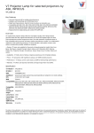
User Guide for FEBFDMQ8203_13 W GreenBridge™ Evaluation Kit for Power Over Ethernet 13 W Flyback DC-DC MLP 4.5x5 GreenBridge™ SSOT-6 150 V MOSFET SSOT-3 30 V MOSFET Featured Fairchild Products: FDMQ8203, FDC86244, FDN537N Direct questions or comments about this evaluation board to: “Worldwide Direct Support” Fairchild Semiconductor.com © 2012 Fairchild Semiconductor Corporation FEBFDMQ8203_13W • Rev. 1.0.0 Table of Contents 1. Introduction ............................................................................................................................... 3 1.1. Description ....................................................................................................................... 3 1.2. Features ............................................................................................................................ 3 2. Evaluation Board Specifications ............................................................................................... 3 3. Photographs............................................................................................................................... 4 4. Printed Circuit Board ................................................................................................................ 5 5. Schematic .................................................................................................................................. 6 6. Bill of Materials ........................................................................................................................ 8 7. Electrical Characteristics ........................................................................................................ 10 8. Setup and Test Procedure........................................................................................................ 11 8.1. Hardware Connector Description ................................................................................... 11 9. Performance of Evaluation Board ........................................................................................... 12 10. Revision History ..................................................................................................................... 13 © 2012 Fairchild Semiconductor Corporation 2 FEBFDMQ8203_13W • Rev. 1.0.0 The following user guide supports the evaluation kit for high-efficiency, IEEE802.3af, Class3 Power over Ethernet Power Device (PoE PD) Flyback DCDC with PoE interface controller. It should be used in conjunction with the FDMQ8203 datasheet as well as Fairchild’s application notes and technical support team. Please visit Fairchild’s website at www.fairchildsemi.com. 1. Introduction This board is designed to rectify the positive and negative power source from Power Source Equipment (PSE) and regulate 48 V (36 V ~ 57 V) to provide 5 VOUT at maximum 2.6 A with 250 kHz switching frequency and over 90% of the total efficiency in the compact power density. It meets the required specification under IEEE802.3af. 1.1. Description This kit contains the MLP 4.5x5 GreenBridge™ MOSFET evaluation board. 1.2. Features 2. GreenBridge™ FDMQ8203 quad P&N-Channel MOSFET Flyback Primary Switch FDC86244 Single N-Channel MOSFET Flyback Secondary Switch FDN537N Single N-Channel MOSFET Controller IEEE802.3at PD with Flyback Controller Output-Voltage Range 5 V, Adjustable by R39 and R37 Switching Frequency 250 kHz, Adjustable by C55 Maximum Output Current 2.6 A, Limited by Power Component Evaluation Board Specifications Table 1. MOSFET Parameters Part Number Location FDMQ8203 Q1, Q4 Q2, Q3 RDS(ON) [mΩ] at 10 VGS Package BVDSS (V) MLP4.5x5 Qg [nC] at 10 VGS COSS [pF] Max. Typ. Typ. 100 110 2.9 41.0 -80 190 13 46 FDC86244 Single SSOT-6 150 144.0 4.2 32.0 FDN537N Single SSOT-3 30 28 5.3 135 © 2012 Fairchild Semiconductor Corporation 3 FEBFDMQ8203_13W • Rev. 1.0.0 3. Photographs Size = 70 X 60 mm. Figure 1. Figure 2. © 2012 Fairchild Semiconductor Corporation Top Side View of Evaluation Kit Bottom Side View of Evaluation Kit 4 FEBFDMQ8203_13W • Rev. 1.0.0 4. Printed Circuit Board PCB Layout (70 mm x 60 mm, 4-Layer). Figure 3. SST (Component Side) Layer Figure 4. SSB (Component) Layer Figure 5. TOP & SMT Layer Figure 6. BOT & SMB Layer Figure 7. INNER1 (GND) Layer Figure 8. INNER2 (POWER) Layer © 2012 Fairchild Semiconductor Corporation 5 FEBFDMQ8203_13W • Rev. 1.0.0 Schematic 5. 1 11 OUT TO PHY 12 10 4 6 1 5 3 7 2 8 9 13 14 15 16 J8 J7 J11 J12 TXCT RXCT MID+ MID- R58 20K P48V C69 1nF 1N4148WS D48 Q49 MMBT2222A D47 1N4148WS MMBT2907A Q50 R59 20K MM5Z10V D49 D46 MM5Z10V Q48 FDMQ8203 C71 1nF MM5Z10V D53 R52 20K 1N4148WS D52 R56 20K C75 1nF 1N4148WS MM5Z10V D60 D61 Q46 MMBT2222A 7 8 Q45 FDMQ8203 6 5 4 Q41 MMBT2222A 9 3 2 6 5 4 1 7 8 9 10 11 Q47 MMBT2907A 12 Q42 MMBT2907A C74 1nF D59 D58 1N4148WS MM5Z10V 3 2 D51 1N4148WS R57 20K 1 R53 10 11 D50 MM5Z10V C72 1nF 20K 12 J28 J29 J30 J31 supportersupporter supporter supporter C70 1nF N48V 16 15 14 13 TRD1+ TRCT1 TRD1TRD2+ TRCT2 TRD2TRD3+ TRCT3 TRD3TRD4+ R63 NC TXCT RXCT MID+ MID- TRD4- TRCT4 T2P 16 15 14 13 IN FROM PSE 2 3 6 5 4 7 8 12nF X 4 75Ohm X 4 1000pF / 2KV 0826-1x1t-gh-f J23 R61 0 R62 NC P48V R54 20K R55 20K D55 1N4148WS MMBT2907A Q44 Q43 MMBT2222A 1N4148WS D56 C76 1nF MM5Z10V D57 D54 MM5Z10V C77 1nF R60 20k D63 SMAJ58A P48V C73 0.082uF/100V N48V GreenBridge™ Block Schematic Figure 9. FEBFDMQ8203_13W • Rev. 1.0.0 6 © 2012 Fairchild Semiconductor Corporation 1 1 1 1 1 1 1 1 1 1 1 1 1 1 1 1 YELLOW_C YELLOW_A GREEN_C GREEN_A 17 18 19 20 SHIELD SHIELD 21 22 P48V L6 SD6020-8r9 C25 2.2uF/100V/1210 T2P R20 20K/2012 C66 C64 1uF C54 3.3nF SHDN VPROTP T2P NC RCLASS PWRGD_BAR NC PWRGD VPORTN NC VPORTN VNEG NC VNEG NC NC SG PG Vcc RGDLY ton RCMP ENDLY CCMP SY NC SENSE+ SFST SENSEOSC UVLO FB VCMP U4 LTC4269-1 22uF/16V/1210 0 1 2 3 4 5 6 7 8 9 10 11 12 13 14 15 16 R35 30ohm 1% R31 10k 32 31 30 29 28 27 26 25 24 23 22 21 20 19 18 17 J21 PWRGD C57 1nF R32 NC R34 39K 1% R27 150/2012 R22 4.7 R33 C59 R40 14K 1% 0.1uF 750 0 C62 100pF/2012 3 R26 12K PCP201 NC 7 8 10 9 T2 POE13P-50L 2 1 3 4 R29 5.1 C53 1.5nF Q6 FDC86244 1uF C67 R38 0.03 1/2W 0 R44 100 3 . . . C43 22uF/16V/1210 Q7 FDN537N 1 Q11 MMBT2907A C52 2.2nF C61 4700pF/250V/1808 PE-68386NL L5 2 + 0 R19 20 R41 39K C56 NC C55 33pF 0 1 2 5 6 4 R30 NC C65 22uF/16V/1210 Q12 MMBT2222A R42 15 R43 10K 1 1 1 J19 +Vout J22 -Vout 1 C60 22uF/16V/1210 MBR0540 D7 R28 47 C63 1uF D8 MBR0540 FEBFDMQ8203_13W • Rev. 1.0.0 7 © 2012 Fairchild Semiconductor Corporation 1 1 D6 BAS21 R39 R36 27K 1% 100k R37 3K 1% J16 GND PoE Power Device Controller and Flyback DC-DC Block Schematic Figure 10. GND 33 J17 VPORT_P N48V J18 VPORT_N 1 1 1 1 1 1 10uF/100V C24 6. Bill of Materials Table 2. Item Qty. Bill of Materials Reference Part Name Vender Comment 1 1 C24 EEE2AA100UP Panasonic 10 µF / 100 V 2 1 C25 GRM32ER72A225KA35 Murata 2.2 µF / 100 V 3 4 C43, C60, C65, C66 C3225X7RIC226M TDK 22 µF / 16 V / 3216 4 1 C52 2.2 nF / 1608 Any 5 1 C53 1.5 nF / 1608 Any 6 1 C54 3.3 nF / 1608 Any 7 1 C55 33 pF / 1608 Any 8 6 R30, R32, C56, R62, R63, PCP201 NC 9 9 C57, C69, C70, C71, C72, C74, C75, C76, C77 1 nF / 1608 10 1 C59 0.1 µF / 1608 Any 11 1 C61 GA343D Murata 12 1 C62 100 pF / 2012 Any 13 3 C63, C64, C67 1 µF / 1608 Any 14 1 C73 C0805C823K1RACTU Kemet 15 1 D6 BAS21 Fairchild Semiconductor 16 2 D7, D8 MBR0540 Fairchild Semiconductor 17 8 D46, D49, D50, D53, D54, D57, D58, D61 MM5Z10V Fairchild Semiconductor 19 8 D47, D48, D51, D52, D55, D56, D59, D60 1N4148WS Fairchild Semiconductor 20 1 D63 SMAJ58A Diodes TVS Diode 21 1 J23 0826-1G1T-GH-F Belfuse RJ45 with Transformer Any 4700 pF / 250 V 0.082 µF / 100 V 10 V Zener Diode 22 1 L5 PE-68386NL Pulse trans 23 1 L6 SD6020-8R9 Coiltronics 8.2 µH 24 1 Q6 FDC86244 Fairchild Semiconductor 150 V 144 mΩ MOSFET 25 1 Q7 FDN537N Fairchild Semiconductor 30 V 28 mΩ MOSFET 26 5 Q11, Q42, Q44, Q47, Q50 MMBT2907A Fairchild Semiconductor 27 5 Q12, Q41, Q43, Q46, Q49 MMBT2222A Fairchild Semiconductor 28 2 Q45, Q48 FDMQ8203 Fairchild Semiconductor 29 1 R19 20 Ω / 2012 Any 30 1 R20 20 kΩ / 2012 Any 31 1 R22 4.7 Ω / 1608 Any 32 1 R26 12 kΩ / 1608 Any 33 1 R27 150 Ω / 2012 Any 34 1 R28 47 Ω / 1608 Any 35 1 R29 5.1 Ω / 1608 Any 36 2 R31, R43 10 kΩ / 1608 Any © 2012 Fairchild Semiconductor Corporation 8 GreenBridge™ Quad MOSFET FEBFDMQ8203_13W • Rev. 1.0.0 Bill of Materials (Continued) Item Qty. Reference Part Name Vender 37 1 R33 14 kΩ 1% / 1608 Any 38 1 R34 39 kΩ / 1% / 1608 Any 39 1 R35 45.3 Ω / 1608 Any 40 1 R36 100 kΩ / 1608 Any 41 1 R37 3 kΩ / 1% / 1608 Any Comment 42 1 R38 0.03 mΩ / 0.5 W HMR 43 1 R39 24 kΩ / 1% / 1608 Any 44 1 R40 750 Ω / 1608 Any 45 1 R41 39 kΩ / 1608 Any 46 1 R42 15 Ω / 1608 Any 47 1 R44 100 Ω / 1608 Any 48 9 R52, R53, R54, R55, R56, R57, R58, R59, R60 20 kΩ / 1608 Any 49 1 R61 0 Ω / 1608 Any 50 1 T2 POE13P-50L Coilcraft 13 W PoE Transformer 51 1 U4 LTC4269-1 LTC PoE Flyback IC © 2012 Fairchild Semiconductor Corporation 9 Shunt Resistor FEBFDMQ8203_13W • Rev. 1.0.0 7. Electrical Characteristics Table 3. Electrical Specification Parameter ™ GreenBridge Value Remark FDMQ8203 Quad P&N-Channel MOSFET, Fairchild Semiconductor Flyback Primary Switch FDC86244 Single N-Channel MOSFET, Fairchild Semiconductor Flyback Secondary Switch FDN537N Single N-Channel MOSFET, Fairchild Semiconductor Controller IEEE802.3at PD with Flyback Controller VOUT Range 5V Adjustable by R39 and R37 Switching Frequency 250 kHz Adjustable by C55 Maximum IOUT 2.6 A Limited by Power Component © 2012 Fairchild Semiconductor Corporation 10 FEBFDMQ8203_13W • Rev. 1.0.0 8. Setup and Test Procedure Table 4. Test Point Descriptions Test Point Label J17 P48 V J18 N48 V Measurement test point for rectified negative input voltage J16 GND Measurement test point for input voltage return J19 +VOUT Measurement test point for output voltage J22 -VOUT Measurement test point for output voltage return 8.1. Descriptions Measurement test point for rectified positive input voltage Hardware Connector Description The evaluation kit is fully assembled and tested. Follow the steps below to verify board operation. 1. Use one of the following methods to power the evaluation kit: If network connectivity is required: Connect a CAT5 Ethernet network cable from the evaluation kit input port RJ45 connector to the corresponding PSE Ethernet LAN connection, which provides power to the evaluation kit. J21 connector provides an interface with the Ethernet data signals only. If network connectivity is not required: Connect a -48 V DC power supply between the TXCT and RXCT. OR connect a -48 V DC power supply between the MID+ and MID-. Caution: Do not turn on the power supply until all connections are completed. 2. Activate the PSE power supply or turn on the external DC power supply. 3. Using a voltmeter, verify that the evaluation kit provides +5 V across the +VOUT and –VOUT pins. –VOUT is isolated from the evaluation kit’s input N48 V and GND pins. © 2012 Fairchild Semiconductor Corporation 11 FEBFDMQ8203_13W • Rev. 1.0.0 9. Performance of Evaluation Board Figure 11 and Figure 12 show measured data. Efficiency & Power loss 92 2.00 90 1.80 1.60 Efficiency(%) 88 1.40 86 1.20 84 1.00 36V Efficiency 48V Efficiency 57V Efficiency 36V Power loss 48V Power loss 57V Power loss 82 80 0.80 0.60 78 0.40 0.5 0.8 1.1 1.4 1.7 Load(A) 2.0 2.3 2.6 Figure 11. Efficiency & Power Loss at VOUT=5 V, Soaking=5 Minutes, fSW=250 kHz GreenBridgeTM FDMQ8203: 31°C Flyback Primary FDC86244: 38.3°C Figure 12. Flyback Secondary FDN537N: 48.1°C Thermal Performance at VIN=48 V, VOUT=5 V, IOUT= 2.6 A, Soaking=5 Minutes, fSW=250 kHz © 2012 Fairchild Semiconductor Corporation 12 FEBFDMQ8203_13W • Rev. 1.0.0 10. Revision History Rev. Date Description 0.1.0 February 13, 2012 Initial Release 1.0.0 Reformat to template November 28, 2012 Proofread and correct content WARNING AND DISCLAIMER Replace components on the Evaluation Board only with those parts shown on the parts list (or Bill of Materials) in the Users’ Guide. Contact an authorized Fairchild representative with any questions. This board is intended to be used by certified professionals, in a lab environment, following proper safety procedures. Use at your own risk. The Evaluation board (or kit) is for demonstration purposes only and neither the Board nor this User’s Guide constitute a sales contract or create any kind of warranty, whether express or implied, as to the applications or products involved. Fairchild warrantees that its products meet Fairchild’s published specifications, but does not guarantee that its products work in any specific application. Fairchild reserves the right to make changes without notice to any products described herein to improve reliability, function, or design. Either the applicable sales contract signed by Fairchild and Buyer or, if no contract exists, Fairchild’s standard Terms and Conditions on the back of Fairchild invoices, govern the terms of sale of the products described herein. DISCLAIMER FAIRCHILD SEMICONDUCTOR RESERVES THE RIGHT TO MAKE CHANGES WITHOUT FURTHER NOTICE TO ANY PRODUCTS HEREIN TO IMPROVE RELIABILITY, FUNCTION, OR DESIGN. FAIRCHILD DOES NOT ASSUME ANY LIABILITY ARISING OUT OF THE APPLICATION OR USE OF ANY PRODUCT OR CIRCUIT DESCRIBED HEREIN; NEITHER DOES IT CONVEY ANY LICENSE UNDER ITS PATENT RIGHTS, NOR THE RIGHTS OF OTHERS. LIFE SUPPORT POLICY FAIRCHILD’S PRODUCTS ARE NOT AUTHORIZED FOR USE AS CRITICAL COMPONENTS IN LIFE SUPPORT DEVICES OR SYSTEMS WITHOUT THE EXPRESS WRITTEN APPROVAL OF THE PRESIDENT OF FAIRCHILD SEMICONDUCTOR CORPORATION. As used herein: 1. Life support devices or systems are devices or systems which, (a) are intended for surgical implant into the body, or (b) support or sustain life, or (c) whose failure to perform when properly used in accordance with instructions for use provided in the labeling, can be reasonably expected to result in significant injury to the user. 2. A critical component is any component of a life support device or system whose failure to perform can be reasonably expected to cause the failure of the life support device or system, or to affect its safety or effectiveness. ANTI-COUNTERFEITING POLICY Fairchild Semiconductor Corporation's Anti-Counterfeiting Policy. Fairchild's Anti-Counterfeiting Policy is also stated on our external website, www.fairchildsemi.com, under Sales Support. Counterfeiting of semiconductor parts is a growing problem in the industry. All manufacturers of semiconductor products are experiencing counterfeiting of their parts. Customers who inadvertently purchase counterfeit parts experience many problems such as loss of brand reputation, substandard performance, failed applications, and increased cost of production and manufacturing delays. Fairchild is taking strong measures to protect ourselves and our customers from the proliferation of counterfeit parts. Fairchild strongly encourages customers to purchase Fairchild parts either directly from Fairchild or from Authorized Fairchild Distributors who are listed by country on our web page cited above. Products customers buy either from Fairchild directly or from Authorized Fairchild Distributors are genuine parts, have full traceability, meet Fairchild's quality standards for handling and storage and provide access to Fairchild's full range of up-to-date technical and product information. Fairchild and our Authorized Distributors will stand behind all warranties and will appropriately address any warranty issues that may arise. Fairchild will not provide any warranty coverage or other assistance for parts bought from Unauthorized Sources. Fairchild is committed to combat this global problem and encourage our customers to do their part in stopping this practice by buying direct or from authorized distributors. EXPORT COMPLIANCE STATEMENT These commodities, technology, or software were exported from the United States in accordance with the Export Administration Regulations for the ultimate destination listed on the commercial invoice. Diversion contrary to U.S. law is prohibited. U.S. origin products and products made with U.S. origin technology are subject to U.S Re-export laws. In the event of re-export, the user will be responsible to ensure the appropriate U.S. export regulations are followed. © 2012 Fairchild Semiconductor Corporation 13 FEBFDMQ8203_13W • Rev. 1.0.0