1
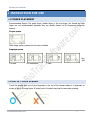
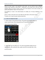
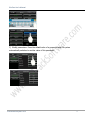
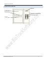
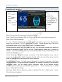
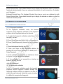
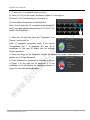
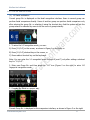
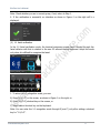
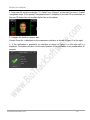
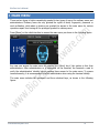
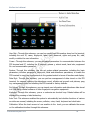
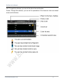
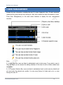
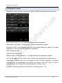
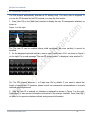
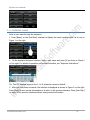
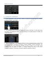
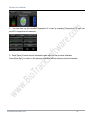
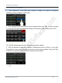
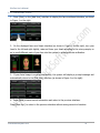
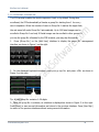
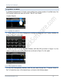
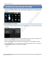
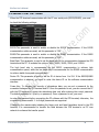
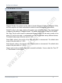
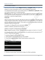
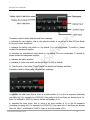
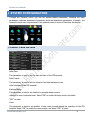
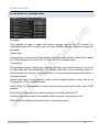
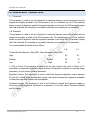
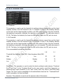
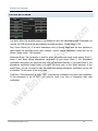
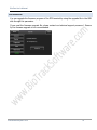
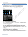
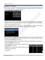
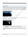
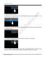
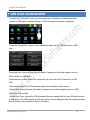
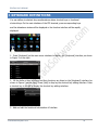
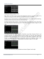
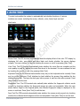
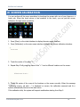
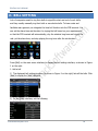
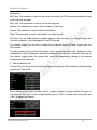
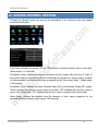
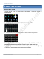
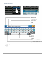
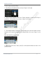
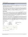
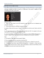
BioFace User’s Manual
www.BiotrackSoftware.com
0
BioFace User’s Manual
CONTENT TABLE
1
INSTRUCTION FOR USE ........................................................................................................................................................1
1.1
FINGER PLACEMENT ................................................................................................................................................................. 1
1.2
USE OF TOUCH SCREEN............................................................................................................................................................. 1
1.3
TOUCH OPERATIONS ................................................................................................................................................................ 2
1.4
BIOFACE DEVICE...................................................................................................................................................................... 4
1.5
MAIN INTERFACE ..................................................................................................................................................................... 5
1.6
VERIFICATION MODES .............................................................................................................................................................. 6
1.6.1 Fingerprint Verification................................................................................................................................................... 6
1.6.2 Facial Verification ........................................................................................................................................................... 8
1.6.3 Password Verification ................................................................................................................................................... 11
1.6.4 ID Card Verification ...................................................................................................................................................... 13
2
MAIN MENU ...................................................................................................................................................................... 15
3
USER MANAGEMENT ......................................................................................................................................................... 18
3.1
ADDING A USER .................................................................................................................................................................... 19
3.1.1 Entering a User ID ......................................................................................................................................................... 20
3.1.2 Entering a Name ........................................................................................................................................................... 21
3.1.3 Enrolling a Fingerprint .................................................................................................................................................. 22
3.1.4 Enrolling a Password .................................................................................................................................................... 24
3.1.5 Enrolling a Face ............................................................................................................................................................ 25
3.1.6 Entering a Group No. .................................................................................................................................................... 26
3.1.7 Enrolling an ID Card ...................................................................................................................................................... 28
3.1.8 Modify User Rights ....................................................................................................................................................... 30
3.2
EDIT A USER ......................................................................................................................................................................... 31
3.3
DELETE A USER...................................................................................................................................................................... 32
3.4
QUERY A USER ...................................................................................................................................................................... 33
3.4.1 Query by User ID ........................................................................................................................................................... 33
3.4.2 3.4.2 Query by Name .................................................................................................................................................... 33
4
COMMUNICATION-RELATED SETTINGS .............................................................................................................................. 35
4.1
NETWORK SETTINGS............................................................................................................................................................... 35
4.2
SERIAL PORT SETTINGS ........................................................................................................................................................... 36
4.3
WIEGAND OUTPUT ................................................................................................................................................................ 37
4.3.1 Wiegand 26-bits Output Description ............................................................................................................................ 38
4.3.2 Wiegand 34-bits Output Description ............................................................................................................................ 39
4.3.3 Customized Format....................................................................................................................................................... 40
5
SYSTEM CONFIGURATION .................................................................................................................................................. 44
5.1
5.2
5.3
5.4
5.5
BASIC PARA METERS............................................................................................................................................................... 44
INTERFACE PARAMETERS ......................................................................................................................................................... 46
FINGERPRINT PARAMETERS...................................................................................................................................................... 47
FACE PARAMETERS ................................................................................................................................................................ 48
LOG SETTINGS ....................................................................................................................................................................... 50
www.BiotrackSoftware.com
1
BioFace User’s Manual
5.6
6
UPDATE ............................................................................................................................................................................... 51
DATA MANAGEMENT ........................................................................................................................................................ 52
6.1
6.2
QUERY A RECORD .................................................................................................................................................................. 53
WORK CODE......................................................................................................................................................................... 54
7
USB DISK MANAGEMENT ................................................................................................................................................... 57
8
KEYBOARD DEFINITIONS .................................................................................................................................................... 59
9
AUTO TEST ......................................................................................................................................................................... 61
10
SCREEN CALIBRATION ........................................................................................................................................................ 63
11
BELL SETTING ..................................................................................................................................................................... 64
12
ACCESS CONTROL SETTING ................................................................................................................................................ 66
13
DATE/TIME SETTING .......................................................................................................................................................... 67
13.1
13.2
14
SYSTEM INFORMATION ..................................................................................................................................................... 71
14.1
14.2
15
SET DATE/TIME..................................................................................................................................................................... 67
SET DAYLIGHT SAVING TIME (DST) ........................................................................................................................................... 68
RECORDS ............................................................................................................................................................................. 71
TERMINAL ............................................................................................................................................................................ 71
APPENDIX .......................................................................................................................................................................... 72
15.1
15.2
15.3
15.4
15.5
TEXT INPUT INSTRUCTIONS ...................................................................................................................................................... 72
RULES FOR UPLOADING PROMOTIONAL PICTURES ........................................................................................................................ 75
INTRODUCTION TO WIEGAND................................................................................................................................................... 76
PHOTO ID FUNCTION ............................................................................................................................................................. 77
ATTENDANCE STATUS SELECTION FUNCTION ............................................................................................................................... 78
www.BiotrackSoftware.com
2
BioFace User’s Manual
1 INSTRUCTION FOR USE
1.1 FINGER PLACEMENT
Recommended fingers: The index finger, middle finger or the ring finger; the thumb and little
finger are not recommended (because they are usually clumsy on the fingerprint collection
screen).
Proper press:
Make finger center pressed on the sensor window
Improper press
Upri
ght
Too lean
Too downward
Slant
1.2 USE OF TOUCH SCREEN
Touch the screen with one of your fingertips or the top of the forward edge of a fingernail, as
shown in the fo llo wing figure. A broad point of contact may lead to inaccurate pointing.
www.BiotrackSoftware.com
1
BioFace User’s Manual
When the touch screen is less sensitive to the touch, you can perform screen calibration
through menu operations. Press [Menu] [Calibration] on the screen and a cross icon will be
displayed. After you touch the center of the cross at five locations on the screen correctly, the
system automatical ly returns to the main menu.
Press [Return] to return to the initial interface. For details, see 10 Screen Calibration in this
manual.
Smear or dust on the touch screen may affect the performance of the touch screen.
Therefore, try to keep the screen clean and dust-free.
1.3 TOUCH OPERATIONS
1) Enter numbers. Press the [User ID] key. The system automatically displays the
number input interface. After entering the user ID, press [OK] to save and
return to the previous interface.
2) Enter Text. Press the [Name] key. The system automatically displays the text
input interface. After entering the user name, press [X] to save and return to the
previous interface.
www.BiotrackSoftware.com
2
BioFace User’s Manual
3) Modify parameters. Press the default value of a parameter and the system
automatically switches to another value of this parameter.
www.BiotrackSoftware.com
3
BioFace User’s Manual
1.4 BIOFACE DEVICE
Indicator
Touch screen
Push buttons
Fingerprint collection area
ID card swipe area
Camera
www.BiotrackSoftware.com
4
BioFace User’s Manual
1.5 MAIN INTERFACE
Menu
Date
1:1 or 1:G Function
Ke y
Time
Switch Key
Attendance
Status
Facial/Fingerprint
Current Gro up No.
Screen Shortcut
Facial/Fingerprint
Image
Menu: You can enter the main menu by touching this key.
Time: Current time is displayed. Both the 12-hour and 24-hour time systems are supported.
Date: Curren t date is displayed.
1:1 or 1:G Function Key:You can enter the digital input interface of 1:1 or 1:G verification
mode. You can set the “1:1/1:G” shortcut key thr ough Screen Shortcut Keys. This key is
automatically hidden if the [Toolbar Style] is set to “Permanent Display”.
Facial/Fingerprint Switch Key: By pressing this key, you can switch between the facial and
fingerprint recognition modes. You can set the “Facial/Fingerprint Switch Key” shortcut key
through Screen Shortcut Keys. This key is automatically hidden if the [Toolbar Style] is set to
“Permanent Display”.
Current Group No.: When the terminal is currently in the facial recognition mode, users in
current group can perform facial comparison directly, while users of another group need to
enter the group No. before performing the facial comparison.
Facial/Fingerprint Image: If a facial image is displayed, the terminal is currently in the facial
recognition mode; if a finger print image is displayed, the terminal is currently in the fingerprint
recognition mode. You can change current recognition mode of the terminal through
Facial/Fingerprint Switch Key, the Facial/Fin gerprint Key in Screen Shortcut Keys or related
key in Keyboard Shortcut Keys.
Attendance Status: Current attendance status is displayed. This key is hidden when
Shortcut Keys are displayed.
www.BiotrackSoftware.com
5
Screen
BioFace User’s Manual
Screen Shortcut Keys: Press related shortcut keys to display the attendance status or enter the
functional interface quickly. Users can customize the function of each shortcut key. For details,
see 8 Keyboard.
Keyboard Shortcut Keys: The Keyboard Shortcut Keys have a one-to-one relationsh ip with
Screen Shortcut Keys. Press related shortcut keys to display the attenda nce status or enter the
functional interface quickly.
1.6 VERIFICATION MODES
1.6.1 FINGERPRINT VERIFICATION
(1) 1:N fingerprint verification
In the fingerprint verification mode, the terminal
compares current fingerprint collected by the fingerprint
collector with all fingerprint data on the terminal.
1. To enter the fingerprint verification mode (Figure 1 on
the right), you can:
A) Press [Facial/Fingerprint Switch Key] on the screen, or
B) Press [Facial/Fingerprint] shortcut key on the screen,
or
C) Press the keyboard shortcut key [F6].
2. Press your finger on the fingerprint collector by
adopting the proper finger placement. For details, see 1.1
Finger Placement.
3. If the verification is successful, an interface as shown
in Fig ur e 2 on the right will be displayed.
4. If the verification is not successful, an interface as
shown in Fig ur e 3 on the
right will be displayed.
(2) 1:1 fingerprint verification
In the 1:1 fingerprint verification mode, the terminal
compares current fingerprint collected through the
fingerprint collector with that in relation to the user ID
entered through keyboard. Adopt this mode only when
it is difficult to recognize the fingerprint.
www.BiotrackSoftware.com
6
BioFace User’s Manual
1. To enter the 1:1 recognition mode, you can:
A) Press [1:1/1:G] on the screen, as shown in Figure 1 on the right, or
B) Press [1:1/1:G] shortcut key on the screen, or
C) Press relate d shortcut key on the keyboard.
Note: You can enter the 1:1 recognition mode through B)
and C) only after setting a shortcut key for “1:1/1:G”. For
details, see 8 Keyboard.
2. Enter user ID and then press the "Fingerprint” icon
(Figure 2 on the right) to
enter 1:1 fingerprint recognition mode. If the prompt
“Unregistered user !” is displayed, the user ID is
nonexistent or the user ID bearer has not enrolled
his/her fingerprint.
3. Press your finger on the fingerprint collector by adopting the proper finger placement. For
details, see 1.1 Finger Placement.
4. If the verification is successful, an interface as shown
in Figure 3 on the right will be displayed. 4. If the
verification is not su ccessful, an interface as shown in
Figure 4 on the right will be displayed.
www.BiotrackSoftware.com
7
BioFace User’s Manual
1.6.2 FACIAL VERIFICATION
(1) 1:G facial verification
Current group No. is displayed on the facial recognition interface. Users in current group can
perform facial comparison directly. Users of another group can perform facial comparison only
after entering the group No. or selecting it using the shortcut key. And the system will set the
group entered or selected by users to be the curre nt group instantly.
1. To enter the 1:G recognition mode, you can:
A) Press [1:1/1:G] on the screen, as shown in Figure 1 on the right, or:
B) Press [1:1/1:G] shortcut key on the screen, or
C) Press relate d shortcut key on the keyboard.
Note: You can enter the 1:1 recognition mode through B) and C) only after setting a shortcut
key for “1:1/1:G”.
2. Enter user Group No. and then press the "1:G” icon (Figure 2 on the right) to enter 1:G
fingerprint recognition mode.
3. Compare the facial in a proper way.
Current Group No. is displayed on the comparison interface, as shown in Figure 3 on the right.
www.BiotrackSoftware.com
8
BioFace User’s Manual
Note: Check whether you are in current group; if not, return to Step 1.
4. If the verification is successful, an interface as shown in Figure 4 on the right will b e
displayed.
(2) 1:1 facial verification
In the 1:1 facial verification mode, the terminal compares current facial collected through the
facial collector with that in relation to the user ID entered through keyboard. Adopt this mode
only when it is difficult to recognize the facial.
1. To enter the 1:1 recognition mode, you can:
A) Press [1:1/1:G] on the screen, as shown in Figure 1 on the right, or:
B) Press [1:1/1:G] shortcut key on the screen, or
C) Press relate d shortcut key on the keyboard.
Note: You can enter the 1:1 recognition mode through B) and C) only after setting a shortcut
key for “1:1/1:G”.
www.BiotrackSoftware.com
9
BioFace User’s Manual
2. Enter user ID and then press the "1:1 Facial” ico n (Figure 2 on the right) to enter 1:1 facial
recognition mode. If the prompt “Unregistered user!” is displaye d, the user ID is nonexistent or
the user ID bearer has not enrolled his/her face in the system.
3. Compare the facial in a proper way.
Current Group No. is displayed on the comparison interface, as shown in Figure 3 on the right.
4. If the verification is successful, an interface as shown in Figure 4 on the right will b e
displayed. The system will retur n to the main interface if the verification is not passed within 20
seconds.
www.BiotrackSoftware.com
10
BioFace User’s Manual
1.6.3 PASSWORD VERIFICATION
In the password verification mode, the te rminal compares the password entered with that in
relation to the user ID.
1. To enter the password verification mode, you can:
A) Press [1:1/1:G] on the screen, as shown in Figure 1 on the right, or:
B) Press [1:1/1:G] shortcut key on the screen, or
C) Press relate d shortcut key on the keyboard.
Note: You can enter the 1:1 recognition mode through B) and C) only after setting a shortcut
key for “1:1/1:G”.
2. Enter the user ID and then press the "Key” icon (Figure 2 on the right) to enter password
verification mode. If the prompt “Unregistered user!” is displaye d, the user ID is nonexistent or
the user ID bearer has not enrolled his/her password in the system.
3. Enter the password and press the “OK” icon to start the password comparison, as shown in
Figure 3 on the right.
www.BiotrackSoftware.com
11
BioFace User’s Manual
4. If the verification is successful, an interface as shown in Figure 4 on the right will b e
displayed.
www.BiotrackSoftware.com
12
BioFace User’s Manual
1.6.4 ID CARD VERIFICATION
Only the products with a built-in ID card module support the ID card verification. The products
with a built-in ID card module support the following two verification modes:
ID Card Only: Users only need to swipe their ID cards for verification.
ID + Facial Verification: After passing the ID card verification, you also need to perform
facial verification.
1) ID Card Only
1. If you have your ID card number enrolled in the system, you can pass the verification by
swiping your ID card at the swiping area in a proper way.
2. If the verification
displayed.
is successful, an interface as shown in Figure 1 on the right will be
3. If the verification is not successful, an interface as shown in Figure 2 on the right will be
displayed.
2) ID + Facial Verification
1. Swipe your ID card properly at the swiping area to enter the 1:1 facial verification mode, as
shown in Figure 1 on the right:
www.BiotrackSoftware.com
13
BioFace User’s Manual
2. Compare the facial in a proper way.
3. If the verification is successful, an interface as shown in Figure 3 on the right will b e
displayed. The system will return to the main interface if the verification is not passed within 20
seconds.
www.BiotrackSoftware.com
14
BioFace User’s Manual
2 MAIN MENU
There are two types of rights respectively granted to two types of users: the ordinary users and
administrators. Ordinary users are only granted the rights of facial, fingerprint, password or
card verification, while admi ni strators are granted the access to the main menu for various
operations apart from having all the privileges granted to ordinary users.
Press [Menu] on the initial interface to access the main menu, as shown in the following figure:
Any user can access the main menu by pressing the [Menu] key if the system is free from
administrators. After administrators ar e configured on the terminal, the terminal n eeds to
verify the administrators’ identity before granting them access to the main menu. To ensure
terminal security, it is recommended to set an administrator when using the terminal initially.
The main menu includes ten submenus and three shortcut keys, as shown in the following
figure:
www.BiotrackSoftware.com
15
BioFace User’s Manual
User Mgt.: Through this submenu, you can bro wse the user information stored on the terminal,
including the user ID, name, fingerprint, facial, card, password, rights and group No.; add,
modify or delete the user information.
Comm.: Through this submenu, you can set related parameters for communication between the
FFR terminal and PC, including the IP address, gatewa y, subnet mask, baud rate, equipment
No. and communication password.
System: Through this submenu, you can set system-related parameters, including the basic
parameters, interface parameters, fingerprint, facial and attendance parameters, to enable the
FFR terminal to meet user requirements to the greatest extent in terms of functions and display.
Data Mgt.: Through this submenu, you can perform management of data stored on the FFR
terminal, for example, deleting the attendance record, all data and promoti onal pictures, purg
ing management rights and resetting the FFR terminal to factory defaults.
Dn/Upload: Through this submenu, you can import user information and attendance data stored
in a USB disk to related software or other fingerprint recognition equipment.
Keyboard: Through this submenu, you ca n customize six shortcut keys. Related status will be
displayed by pressing re lated status key.
Auto Test: This submenu enables the system to automatically test whether functions of various
mo dules are normal, including the screen, collector, voice, facial, keyboard and clock tests.
Calibration: When the touch screen is l ess sensitive to the touch, you can calibrate the screen
on the calibration interface through this submenu.
www.BiotrackSoftware.com
16
BioFace User’s Manual
Bell: Through this submenu, you can set the alarm time and duration.
Access: Through this submenu, you can set the parameters of the electronic locks and related
access control devices.
www.BiotrackSoftware.com
17
BioFace User’s Manual
3 USER MANAGEMENT
Browse the user information, including the user ID, name, fingerprint, face, ID card, password,
rights and the group that the user belongs to. Add, edit or delete the basic information of users.
Press [User Management] on the main menu interface to display the user management
interface.
Note:
1) In User List Area, users are listed in alphabetical order by last name. If you select a user in
User List Area, you can access the editing interface of this user to edit or delete related user
information.
2) In Character Selection Bar, users are listed in alphabetical order by last name by default and
you can locate the desired user quickly. You can press [Query] to locate and q uer y a user
through the user ID.
www.BiotrackSoftware.com
18
BioFace User’s Manual
3.1 ADDING A USER
Press [Add] on the [User Mgt.] interface to display the [Add User] interface as shown below.
User ID: Enter a user ID. 1- to 9-digit user IDs are supported by default.
Name: Enter a user name. 12-character user names are supported by default.
Fingerprint: Enroll a user’s fingerprint and the FFR terminal displays the number of enrolled
fingerprints. A user can enroll 10 fingerprints at maximum.
Face: Enroll a user’s face.
Card: Enroll a user's ID card.
Password: Enroll a user’s password. 1- to 8-digit passwords are supported by default.
Role: Set the rights of a user. A user is set to ordinary user by default and can also be set to
Administrator . Ordinary users are only granted the rights of facial, fingerprint or password
verification, wh ile administrators are granted the access to the main menu for various
operations apart from having all the privileges granted to ordinar y users.
Group No.: Set the group that the user belongs to. Valid group No.: 1– 24.
www.BiotrackSoftware.com
19
BioFace User’s Manual
3.1.1 ENTERING A USER ID
The FFR terminal automatically allocates an ID starting from 1 for every user in sequence. If
you use the ID allocated by the FFR terminal, you may skip this section.
1. Press [User ID] on the [Add User] interface to display the user ID management interface, as
shown in
Figure 1 on the right.
Tip: The user ID can be modified during initial enrollment, but once enrolled, it cannot be
modified.
2. On the displayed keyboard interface, enter a user ID and press <O K> as shown in Figure 2
on the right. If a prompt message “The user ID already exists!” is displayed, enter another ID.
Tip: The FFR terminal supports 1- to 9-digit user IDs by default. If you need to extend the
length of current user ID numbers, please consult our commercial representatives or fore-sale
technical support personnel.
3. After the user ID is entered, an interface is displayed as shown in Figure 3 on the right.
Press [Save] to save current information and return to the previous interface. Press [User Mgt.]
to return to the previous interface without saving current information.
www.BiotrackSoftware.com
20
BioFace User’s Manual
3.1.2 ENTERING A NAME
Enter a user name through the keyboard.
1. Press [Name] on the [Add User] interface to display the name input interface, as sh own in
Figure 1 on the right.
2. On the displayed keyboard interface, enter a user name and press [X] as shown in Figure 2
on the right. For details of operations on keyboard interface, see “Keyboard Instructions”.
Tip: The FFR terminal supports the 1- to 12-character names by default.
3. After the user name is entered, the interface is displayed as shown in Figure 3 on the right.
Press [Save] to save current information an d return to the previous interface. Press [User Mgt.]
to return to the previous interface without saving current information.
www.BiotrackSoftware.com
21
BioFace User’s Manual
3.1.3 ENROLLING A FINGERPRINT
1. Press [Fingerprint] on the [Ad d User] interface to display the [Enroll Fingerprint] interface,
as shown in Figure 1 on the right.
2. On the displayed [Enroll Fingerprint] interface (as shown in the Figure 2 on the right), place
your finger on the fingerprint collector properly according to the system prompt. For details, see
“Finger Placement”.
3. Place the same finger on the fingerprint collector for three consecutive times correctly. If the
enrollment succeeds, the system will display a prompt message “Enrolled Successfully” and
automatically return to the [Add User] interface (as shown in Figure 4 on the right). If the
enrollment fails, the system will displa y a prompt message and return to the [Enroll
Fingerprint] interface. In this case, you need to repeat the operations of step 2.
www.BiotrackSoftware.com
22
BioFace User’s Manual
4. You can back up the enrolled fingerprint of a user by pressing [Fingerprint]. A user can
enroll 10 fingerprints at maximum.
5. Press [Save] to save current information and return to the previous interface.
Press [User Mgt.] to return to the previous interface without saving current information.
www.BiotrackSoftware.com
23
BioFace User’s Manual
3.1.4 ENROLLING A PASSWORD
1. Press [Password] on the [Add User] interface to display the password management
interface, as shown in Figure 1 on the right.
2. On the displayed keyb oard interface, enter a password and press <OK> as shown in Figure
2 on the right. Re-enter the password according to the system prompt and then press <OK>.
Tip: The FFR terminal supports the 1- to 8-digit passwords by default.
3. After the password is entered, an interface is displayed as shown in Figure 3 on the right.
Press [Save] to save current information and return to the previous interface. Press [User Mgt.]
to return to the previous interface without saving current information.
www.BiotrackSoftware.com
24
BioFace User’s Manual
3.1.5 ENROLLING A FACE
1. Press [Face] on the [Add User] interface to display the face enrollment interface, as shown
in Figure 1 on the right.
2. On the displayed face enro llment interface (as shown in Figure 2 on the right), turn your
head to the left and right slightly, raise and lower your head according to the voice prompts, so
as to enroll different parts of your face into the system to assure accurate verification.
3. If your facial image is enrolled successfully, the system will display a prompt message and
automatically return to the [Add User] interface (as shown in Figure 4 on the right).
4. Press [Save] to save current information and return to the previous interface.
Press [User Mgt.] to return to the previous interface without saving current information.
www.BiotrackSoftware.com
25
BioFace User’s Manual
3.1.6 ENTERING A GROUP NO.
The FFR terminal enables the facial comparison functi on by default. During face
enrollment, the FFR automatically al locates a group No. starting from 1 for ever y
user in sequence. When the number of users in Group No.1 reaches the upper limit,
the rest users fall under Group No.2 automatically. Up to 100 facial images can be
enrolled in Group No.1 and only 50 facial images can be enrolled in other groups. If
you use the group No. allocated by the FFR terminal, you may skip this section.
1. Press [Group No.] on the [Add User] interface to display the group No. management
interface, as shown in Figure 1 on the right.
2. On the displayed keyboard interface, enter your gr oup No. and press <OK> as shown in
Figure 2 on the right.
Tip: A valid group No. contains 1–24 digits.
3. After the group No. is entered, an interface is displayed as shown in Figure 3 on the right.
Press [Save] to save current information and return to the previous interface. Press [User Mgt.]
to return to the previous interface without saving current information.
www.BiotrackSoftware.com
26
BioFace User’s Manual
Tip: Please remember your own group No.
www.BiotrackSoftware.com
27
BioFace User’s Manual
3.1.7 ENROLLING AN ID CARD
1. Press [Card] on the [Add User] interface to display the [Enroll Card] interface, as shown in
Figure 1 on the right.
2. The [Punch Card!] interface pops o ut as shown in Figure 2 on the right. Swipe your ID card
properly in the swiping area.
3. If the card passes the verification, the FFR terminal displays a prompt message “Read
Successfully! Card No.: **********”, as sho wn in Figure 3 on the right, and returns to the
[Add User] interface. Press [Card] to display the enrolled card number as shown in Figure 4 on
the right.
4.
Press [Save] to save current information and return to the previous interface.
Press [User Mgt.] to return to the previous interface without saving current information.
www.BiotrackSoftware.com
28
BioFace User’s Manual
www.BiotrackSoftware.com
29
BioFace User’s Manual
3.1.8 MODIFY USER RIGHTS
1. On the [Add User] interface, press [Role:User] to change the user into an administrator, as
shown in Figure 1 on the right.
Note: There are two types of rights respectively granted to two types of users: the ordinary
users and administrators. Ordinary users are only granted the rights of facial, fingerprint, or
password verification, while administrators are granted the access to the main menu for various
operations apart from having all the privileges granted to ordinary users.
2. After the modification is done, the interface is as shown in Figure 2 on the right. Press
[Save] to save current information and return to previous interface; press [User Mgt.] to directly
return to previous interface without saving current information.
www.BiotrackSoftware.com
30
BioFace User’s Manual
3.2 EDIT A USER
Select a user from the User List to enter [User Info] interface.
The User ID cannot be modified, and the other operations are similar to those performe d to
add a user. You can re-enroll your fingerprint and facial image, change your password and
modify the management rights and group No.
www.BiotrackSoftware.com
31
BioFace User’s Manual
3.3 DELETE A USER
On the [User Info] interface, you can delete all or partial user information.
1. Press [Delete] to delete a user, as shown in Figure 1 on the right.
2. On the interface displayed (as shown in Figure 2 on the right), click [YES] to delete current
user and [NO] to return to previous interface.
3. On the [User Info] interface, press [Name], [Fingerprint], [Face] or [Password] to delete
related user information.
www.BiotrackSoftware.com
32
BioFace User’s Manual
3.4 QUERY A USER
To facilitate administrators to locate a user quickly from a large number of enrolled users, the
FFR terminal enables user query by his/her “User ID” and “Name”.
(Location Search)
3.4.1 QUERY BY USER ID
1. Press [Query] on the [User Management] interface to display the User ID query interface, as
shown in Figure 1 on the right.
2. Enter the user ID on the displayed interface, and click [OK] (as shown in Figure 2 on the
right) to locate the cursor to the desired user (as shown in Figure 3 on the right).
3.4.2 3.4.2 QUERY BY NAME
On the [User Management] interface, enter the user name through the “ Character Selecti on
Bar” to locate the cursor to the desired user, as shown in the following figure:
www.BiotrackSoftware.com
33
BioFace User’s Manual
By selecting a character from the “Character Selecti on Bar”, you can quickly locate the users
wh ose names start with this chara cter. Users are listed in alphabetical order by last name by
default.
www.BiotrackSoftware.com
34
BioFace User’s Manual
4 COMMUNICATION-RELATED SETTINGS
You can set related parameters for the communication between the FFR terminal and PC,
including the IP address, gateway, subnet mask, baud rate, equipment No. and communication
password.
4.1 NETWORK SETTINGS
When the FFR terminal communicates with the PC over Ethernet, you need to check the followi
ng settings:
IP Address: The IP address is 192.168.1.201 by default and can be changed as required; the IP
address of the FFR terminal and that of the PC cannot be duplicated.
Subnet Mask: The subnet mask is 255.255.255.0 by default and can be changed as required.
Gateway: The gateway is 0.0.0.0 by default. If the FFR terminal and the PC are not located in
the same network segment, you need to set the gateway.
www.BiotrackSoftware.com
35
BioFace User’s Manual
4.2 SERIAL PORT SETTINGS
When the FFR terminal communicates with the PC over serial ports (RS232/RS485), you need
to check the following settings:
RS232:This parameter is used to enable or disable the RS232 communication. If the RS232
communication cables are used, set this parameter to “ON”.
RS485:This parameter is used to enable or disable the RS485 communication. If the RS485
communication cables are used, set this parameter to “ON”.
Baud Rate: This parameter is used to set the baud rate for the communication between the FFR
terminal and the PC. It includes five options: 9600, 19200, 38400, 57600, and 115200.
The high baud rate is recommended for the RS232 communication to achieve high
communication speed, while the low baud rate is recommended for the RS485 communication
to achieve stable low-speed communication.
Device ID: This parameter is used to set the ID of device from 1 to 254. If the RS232/RS485
communication is adopted, you need to enter the device ID on the software communication
interface.
Comm Key: To enhance the security of attendance data, you can set a password for the
connection between the FFR terminal and PC. Once the password is set, you can connect the PC
with the FFR terminal to access the attendance data only after entering the correct password.
The default password is 0 (that is, no password). Once a password is set, you need
to enter this password before connecting the PC software with the FFR terminal; otherwise, the
connection is unsuccessful. 1- to 6-digit passwords are supported.
Considering the massive data including the finger print and facial templates stored in the FFR
terminal, it is recommended to transfer the data between the FFR terminal a nd PC over
network to enhance the transfer speed.
www.BiotrackSoftware.com
36
BioFace User’s Manual
4.3 WIEGAND OUTPUT
Wiegand Format: The system has two built-in formats Wiegand 26-bits and Wiegand 34-bits,
and also supports the format customization function to meet individualized requirements.
Failed ID: refers to the value output by the system upon verification failure. The output format
is subject to the setting of “Wiegand Format”. The default value scope of Failed ID is 0–65535.
Site Code: The site code is used for customized Wiegand format. The site code is similar to the
device ID, but the site code i s customizable and can be duplicated among different devices.
The default value scope of the site code is 0–255.
Pulse Width: refers to the wi dth of the Wieg and pulse in microseconds. The default value
scope of the pulse width is 1–1000.
Pulse Interval: refers to the interval of the Wiegand pulse in microseconds. The default value
scope of the pulse width is 1–10000.
Output: refers to the contents output upon successful verification. You can select the “User ID”
or “Card Number” as the output.
www.BiotrackSoftware.com
37
BioFace User’s Manual
4.3.1 WIEGAND 26-BITS OUTPUT DESCRIPTION
The system has a built-in Wiegand 26-bits format. Press [Wiegand Format], and select
“Standard Wiegand 26-bits”.
The composition of the Wiegand 26-bits format contains 2 parity bits and 24 bits for output
conte nts (“User ID” or “Card Number”). The binary code of 24-bits represent up to 16,777,216
(0–16,777,215) different values.
1
-
2
-
25 26
Even parity - User ID/Card Number - Odd parity bit
Definition of Fields:
Even parity bit: Judged from bit 2 to bit 13. The even parity bit is 1 if the character has an even
number of 1 bits; other wise, the even parity bit is 1.
User ID/Card: User ID/Card Number (Card Code, 0–16777215) Number (bit 2- bit 25) Bit 2 is
the Most Significant Bit (MSB).
Odd parity bit: Judged from bit 14 to bit 25. The odd parity bit is 1 if the character h as an even
number of 1 bits; otherwise, the odd parity bit is 0.
For example, for a user with user ID of 12345, the enrolled card number is 0013378512 and
the failed ID is set to 1.
1) When the output is set to “User ID”, the Wiegand output is as follows upon successful
verification: 0 0 0 0 0 0 0 0 0 0 0 1 1 0 0 0 0 0 0 1 1 1 0 0 1 1
Even parity bit User ID = Binary code of 12345
Odd parity bit
2) When the output is set to “Card Number”, the Wiegand output is as follows upon successful
verification: 1 1 1 0 0 1 1 0 0 0 0 1 0 0 0 1 1 1 1 0 1 0 0 0 0 0
Even parity bit User ID = Binary code of 0013378512 Odd parity bit
3) The Wiegand output is as follows upon verification failure:
00000000000000000000000010
Even parity bit Failed ID = Binary code of 1
Odd parity bit
Note: If the output contents exceed the scope allowed for the Wiegand format, the last several
bits will be adopted and first several bits are automatically discarded. For example, the user ID
888 888 888 is 110 100 111 110 110 101 111 000 111 000 in binary format. Wiegand26 only
supports 24 bits, that is, it only outputs the last 24 bits, and first 6 bits “110 100” are
automatically discarded.
www.BiotrackSoftware.com
38
BioFace User’s Manual
4.3.2 WIEGAND 34-BITS OUTPUT DESCRIPTION
The system has a built-in Wiega nd 34-bits format. Press [Wiegand Format], and select
“Standard Wiegand 34-bits”.
The composition of the Wiegand 34-bits format contains 2 parity bits and 32 bits for output
conte nts (“User ID” or “Card Number”). The binary code of 32-bits represent up to
4,294,967,296 (0–4,294,967,295) different valu es.
1
-
2
Even - User ID/Card Number
-
33 34
- Odd parity bit
Field Meaning
Even parity bit: Judged from bit 2 to bit 17. The even parity bit is 1 if the character has an
even number of 1 bits; otherwise, the even parity bit is 1.
User ID/Card: User ID/Card Number (Card Code, 0–4,294,967,295) Number (bit 2- bit 33)
Bit 2 is the Most Significant Bit (MSB).
Odd parity bit: Judged from bit 18 to bit 33. The odd parity bit is 1 if the character has an
even number of 1 bits; otherwise, the odd parity bit is 0.
For example, for a user with user ID of 123456789, the enrolled card number is 0013378512
and the failed ID is set to 1.
1) When the output is set to “User ID”, the Wiegand output is as follows upon successful
verification:
0000001110101101111001101000101011
Even parity bit User ID = Binary code of 123456789
Odd parity bit
2) When the output is set to “Card Number”, the Wiegand output is as follows upon successful
verification:
0000000001100110000100011110100001
Even parity bit User ID = Binary code of 0013378512
Odd parity bit
3) The Wiegand output is as follows upon verification failure:
0000000000000000000000000000000010
Even parity bit Failed ID = Binary code of 1
www.BiotrackSoftware.com
Odd parity bit
39
BioFace User’s Manual
4.3.3 CUSTOMIZED FORMAT
Apart from the two built-in formats Wiegand 26-bits and Wiegand 34-bits, the system also
supports the format customization function to meet individualized requirements.
The customized format consists of two character strings: the data bits and parity bits. These
two character strings need to be defined separately.
Data bits define the number of binary bits output by Wiegand as well as the meaning of each
bit. The data bits output by Wiegand can be a card number (C), site code (s), facility code (f),
manufactur er code (m) and parity bits (p).
Parity bits
define the check mode of each bit in data bits and ensure the correctness of data bits during
transfer through the parity check. The parity bits can be set to odd check (o), even check (e)
and both odd check and even check (b). There exists a one-to-one correspondence relationship
between the data bits and parity bits.
For exampl e, the Wiegand26 can be customized as follows:
Definition of data bits: pssssssssccccccccccccccccp
Definition of parity bits: eeeeeeeeeeeeeooooooooooooo
Note: Wiegand26 consists of 26 bits. The first bit is the even parity b it of bits 2 to 13; the 26th
bit is the odd parity bit of bits 14 to 25; the second to the ninth bits are the site code; the 10th
to the 25th bits are the card number.
To customize Wiegand format, proceed as follows:
1) Select [Define Format] and the [Set] key is then enabled.
2) Press [Set] to display the [User Define Format] interface, as shown in the
following figure:
3) Click the e ntry box below “Card Format” to displa y the followi ng interface:
www.BiotrackSoftware.com
40
BioFace User’s Manual
Characters used to define data bits and their meanings:
c: indicates the card number, that is, the output contents, it can be set to User ID/Card Numb
er throug h menu operations.
f: indicates the facility code which is 0 by default. It is not configurable. To modify it, please
contact the equipment supplier.
m: indicates the manufacturer code which is 0 by default. It is not configurable. To modify it,
please contact the equipment supplier.
p: indicates the parity position.
s: indicates th e site code which can be set from 0 to 255 by default.
4) Click the entr y box below “Parity Format” to display the following interface:
Characters used to define parity bits and their meanings:
o: indicates the odd check, that is, there is an odd number of 1’s in the bit sequence (including
one parity bit). For example, for 1000110(0), the parity bit is 0 and there are already three 1’s.
After 0 is suffixed to 1000110, there is still an odd number of 1’s.
e: indicates the even check, that is, there is an even number of 1’s in the bit sequence
(including one parity bit). For example, for 1000110(1), the parity bit is 1 and there are already
three 1’s. After 1 is suffixed to 1000110, there is an even number of 1’s.
www.BiotrackSoftware.com
41
BioFace User’s Manual
b: indicates both odd check and even check.
For example: Definitions of several universal Wiegand formats.
Wiegand34
Data bits:
pccccccccccccccccccccccccccccccccp
Parity bits:
eee eeeeeeeeeeeeeeooooooooooooooooo
Note: Wiegand34 consists of 34 bits. The first bit is the even parity bit of bits 2 to 17; the 34th
bit is the odd parity bit of bits 18 to 33; the second to the ninth bits are the site code; the 10th
to the 25th bits are the card number.
Wiegand37a
Data bits: pmmmmsssssssssssscccccccccccccccccccp
Parity bits: oeobeobeobeobeobeobeobeobeobeobeobeoe
Note: Wiegand37a consists of 37 bits. The first bit is the odd parity bit of bits 3, 4, 6, 7, 9, 10,
12, 13, 15, 16, 18, 19, 21, 22, 24, 25, 27, 28, 30, 31, 33, 34 and 36; the 37th bit is the odd
parity bit of bits 2, 4, 5, 7, 8, 10, 11, 13, 14, 16, 17, 19, 20, 22, 23, 25, 26, 28, 29, 31, 32, 34
and 35; bits 4, 7, 10, 13, 16, 19, 22, 25, 28, 31 and 34 participate in both odd and even parity
check. Bits 2 to 5 are manufactur er code; bits 6 to 1 7 are the site code; bits 18 to 36 are the
card number.
Wiegand37
Data bits:
pmmmffffffffffssssssccccccccccccccccp
Parity bits:
eee eeeeeeeeeeeeeeeooooooooooooooooooo
Note: Wiegand37 consists of 37 bits. The first bit is the even parity bit of bits 2 to 18; the 34
bit is the odd parity bit of bits 19 to 36; the second to the fourth bits are the manufacturer cod
e; the 5 to the 14
bits are facilitate code; the 15 to the 20 bits are the site code; the 21 to the 36 bits are the
card number.
Wiegand50
Data bits: pssssssssssssssssccccccccccccccccccccccccccccccccp
www.BiotrackSoftware.com
42
BioFace User’s Manual
Parity bits:
eee eeeeeeeeeeeeeeeeeeeeeeooooooooooooooooooooooooo
Note: Wiegand50 consists of 50 bits. The first bit is the even parity bit of bits 2 to 25; the 50
bit is the odd parity bit of bits 26 to 49; the second to the 16 bits are the site code; the 17
to the 49 bits are the card number.
www.BiotrackSoftware.com
43
BioFace User’s Manual
5 SYSTEM CONFIGURATION
Through the [System] menu, you can set system-related parameters, including the basic
parameters, interface parameters, fingerprint, facial and attendance parameters, to enable the
terminal to meet user requirements to the greatest extent in terms of functions and display.
5.1 BASIC PARA METERS
Date/Time:
This parameter is used to set the date and time of the FFR terminal.
Date Format:
This parameter is used to set the format of the date displayed on the
initial interface of the FFR terminal.
Keyboard Beep:
This parameter is used to set whether to generate beep sound in
response to every keyboard touch. Select “ON” to enable the beep sound, and select
“OFF” to mute.
Voice:
This parameter is used to set whether to play voice prompts during the operation of the FFR
terminal. Select “ON” to enable the voice prompt, and select “OFF” to mute.
www.BiotrackSoftware.com
44
BioFace User’s Manual
Volume (%):
This parameter is used to adjust the volume of voice prompts.
Power Key:
This parameter is used to set whether to lock the power key. Select “ON” to disable the power
key. If you select “OFF” and press the power key, the FFR terminal will be shut down in three
seconds.
www.BiotrackSoftware.com
45
BioFace User’s Manual
5.2 INTERFACE PARAMETERS
Language:
This parameter is used to display the current language used by the FFR terminal. For
multilingual-capable FFR terminals, you can switch between different languages through this
parameter.
Display Style:
This parameter is used to set the time display mode of the initial interface. Select “ON” to adopt
the 24-hour display mode. Select “OFF” to adopt the 12-h our display mode.
Toolbar Style:
This parameter is used to display style of the shortcut keys on the initial interface. It can be set
to “Auto Hide” and “Permanent Displa y”. By selecting “Auto Hide”, you can manually displa y or
hide the toolbar. By selecting “Permanent Displ ay”, you can permanently display the toolbar on
the initial interface.
Default Verify Mode: This parameter is used to set the default verification mode, that is, the
"Fingerprint" or “Face” verification mode.
Picture Delay (S): This parameter is used to set the picture cycle interval (value scope: 3-999
seconds).
Sleep Time (S): This parameter is used to specify a period after which the FFR
terminal is put in sleep mode if not operated within this period. You can bring up the
FFR terminal from sleep by pressing any key or touching the screen.
www.BiotrackSoftware.com
46
BioFace User’s Manual
5.3 FINGERPRINT PARAMETERS
1: 1 Threshold:
This parameter is used to set the threshold of matching between current fingerprint and the
fingerprint template enrolled in the FFR terminal in the 1:1 verification mo de. If the similarity
betwe en current fingerprint and the fingerprint template e nrol led in the FFR terminal is larger
than this threshold, the matching is successful; otherwise, the matching is not successful.
1:N Threshold:
This parameter is used to set the threshold of matching between current fingerprint and the
fingerprint template enrolled in the FFR terminal in the 1:N verification mo de. If the similarity
betwe en current fingerprint and the fingerprint template e nrol led in the FFR terminal is larger
than this threshold, the matching is successful; otherwise, the matching is not successful.
The recommended thresholds are as follows:
1: N
1:1
25
Threshold False Rejection Rate (FRR)- False Acceptance Rate (FAR)
High
-
Low
45
Medium
-
Medium
35
15
Low
-
High
25
10
1:1 Ret ry Times: This parameter is used to set the retry times in the event of failure of 1:1
verification or password verificatio n due to absence of fingerprint enrollment or improper finger
placement, so as to avoid repetitive operations.
Algorithm Version: This parameter is used to select the fingerprint algorithm version between
9.0 and 10.0. Please select the algorithm version with caution because the fingerprint templates
of these two algorithm versions are incompatible.
Fingerprint Image: This parameter is used to set whether to display the fingerprint image on
the screen during fingerprint enrollment or comparison. It has two values: Permanent Display
and No Display.
www.BiotrackSoftware.com
47
BioFace User’s Manual
5.4 FACE PARAMETERS
1:1 Threshold:
This parameter is used to set the threshold of matching between current face and the facial
template enrolled in the FFR terminal in the 1:1 verificati on mode. If the similarity between
current face and the facial template enrolled in the FFR terminal is larger than this threshold,
the matching is successful; otherwise, the matching is not successful. The valid value scope is
55-120. The higher the threshold, the lower the FAR and the higher the FRR, and vice versa.
1:1:N Threshold:
This parameter is used to set the threshold of matching between current face and the facial
template enrolled in the FFR terminal in the 1:N verificati on mode. If the similarity between
current face and the facial template enrolled in the FFR terminal is larger than this threshold,
the matching is successful; otherwise, the matchin g is not successful. The valid value scope is
65-120. The higher the threshold, the lower the FAR and the higher the FRR, and vice versa.
The recommended thresholds are as follows:
1: N
1:1
Threshold False Rejection Rate (FRR)- False Acceptance Rate (FAR)
High
-
Low
90
80
Medium
-
Medium
80
70
Low
-
High
75
75
Enroll Mode: This parameter is used to select the facial enrollment mode between “Combined
Enroll” and “Face”. In the “Combined Enroll” mo de, users need to enroll their fingerprints or
passwords after facial enrollment; in the “Face” mode, users only need to enroll their facial
images. The “Face” mode is unavailable for the administrators beca use the “Combined Enroll”
mode is mandatory for them by default.
Exposure: This parameter is used to set the exposure value of the camera.
www.BiotrackSoftware.com
48
BioFace User’s Manual
Gain: This parameter is used to set the gain value of the camera.
Quality: This parameter is used to set a quality threshold for the facial images obtained. The
FFR terminal accepts the facial images and processes them by adopting the facial algorithm
when their quality is higher than the threshold; otherwise, it filters these facial images.
Note: Improper adjustment of the Exposure, Gain and Quality parameters may seve rely affect
the performance of the FFR terminal. Please adjust the Exposure parameter only under the
guidance of the after-sales service personnel from our company.
www.BiotrackSoftware.com
49
BioFace User’s Manual
5.5 LOG SETTINGS
Log Alert: When the available space is insufficient to store the specified number of attenda nce
records, the FFR terminal will automatically generate an alarm. (Value scope: 1-99)
Dup. Punch Period (m): If a user’s attendance recor d already exists and the user punches in
again within the specified period (unit: minute), his/her second attendance record will not be
stored. (Value scope: 1-60 minutes)
Workcode Mode: This parameter is used to select the work code input mode among Mode 1,
Mode 2 and None during attendance verification. If you select Mode 1, the attendance
verification starts after you input the work code on the initial interface; if you select Mode 2, the
attendance verification starts before you input the work code on the initial interface; if you
select None, you do not need to input the work code during attendance verification on the initi
al interface. For the input of the work code.
Card Only: If this parameter is set to “YES”, you pass the verification only after card verification.
If this parameter is set to “NO”, you need to verify your face or fingerprint after card
verification.
www.BiotrackSoftware.com
50
BioFace User’s Manual
5.6 UPDATE
You can upgrade the firmware program of the FFR terminal by using the upgrade file in the USB
disk through this parameter.
If you need the firmware upgrade file, please contact our technical support personne l. Genera
lly the firmware upgrade is not recommended.
www.BiotrackSoftware.com
51
BioFace User’s Manual
6 DATA MANAGEMENT
Through the [Data Mgt.] menu, you can perform management of data stored on the
FFR terminal, for example, deleting the attendance record, all data and promotional
pictures, purging management rights and resetting the FFR terminal to factory
defaults.
Delete Transactions: Delete all the attendance records.
Delete All Data: Delete all the information of enrolled personnel, including their fingerprints,
facial images and attendance records.
Clear Administrator: Change all administrators to ordinary users.
Delete Picture: Purge the promotional pictures uploaded from USB disks to the FFR terminal.
Restore to Factory Settings: Restore all parameter settings on the FFR terminal to factory
settings.
Record: Query the attendance records of employees within a specified time range.
WorkCode: Add, edit or delete the work codes of employees.
The employee information and attendance records will not be deleted during restoration to
factory
www.BiotrackSoftware.com
52
BioFace User’s Manual
6.1 QUERY A RECORD
After check-in successfull y, the employee’s attendance records are saved in the FFR terminal.
You can easily query these attendance records.
User ID: Enter the user ID of the employee to query. If this field is left blank, you can query the
attendance records of all the employees. If you enter a user ID, you can query the attendance
record of the employee with this user ID.
Query Time Period: Select a time period to query, including the customized time period,
yesterday, this week, l ast week, this month, last month, and a ll time periods.
Start and End: When you select a customized time period, you need to input a start time and an
end time. When you select other options for time period, the start and end time will be
automatically adjusted to the related time.
After setting the quer y conditions, press [Query] and the records that meet the specified query
conditions will be displa yed on screen.
Select the row where the desired record is located, you can
query the detailed information
of this record, for example, the detailed attendance record
of the employee with user ID
2 on January 7
www.BiotrackSoftware.com
53
BioFace User’s Manual
6.2 WORK CODE
Employees’ salaries are subject to their attend ance records. Emplo yees may be engaged in
different types of work which may vary with time periods. Considering the salaries vary with
work types, the FFR terminal provides a parameter to indicate the corresp ond ing work type for
every attendance record to facilitate rapid understanding of different attendance situations
during the handling of attendance data.
1. Add a work code
1) Press [Add] on the [WorkCode] interface (as shown in Figure 1 on the right) to display the
[Add] interface. No.: A digital code of the work code.
Label: The meaning of the work code.
2) Press the corresponding entry button of [No.] on the [Add] interface (as shown in Figure 2
on the right) to display the No. entry i nterface. On this interface, enter a No.
3) Press the corresponding entry button of [Label] on the [WorkCode] interface (as shown in
Figure 3 on the right) to display the text entry interface. On this interface, enter a label of work
code.
www.BiotrackSoftware.com
54
BioFace User’s Manual
2. Edit and delete a work code
1) Press the row of a work code on the [WorkCode] interface (as shown in Figure 1 on the
right) to display the [Edit] interface.
2) To edit this work code, enter a new No. and label with the same operation steps as described
in “Add a work code”.
3) To delete this work code, press [Delete] (as shown in Figure 3 on the right).
4) On the displayed prompt interface, press <YES> to confirm the deletion of this work code,
and press <NO> to cancel the deletion operation (as shown in Figure 4 on the right).
www.BiotrackSoftware.com
55
BioFace User’s Manual
www.BiotrackSoftware.com
56
BioFace User’s Manual
7 USB DISK MANAGEMENT
Through the [Dn/Upload] menu, you can import user information and attendance data
stored in a USB disk to related software or other fingerprint recognition equipment.
Download Transactions: Import all the attendance data from the FFR terminal to a USB
disk.
Download User: Import all the user information, fingerprints and facial images from the
FFR terminal to a USB disk.
Download user photos: Import the employees’ ph otos from the FFR terminal to a USB
disk.
Only several types of the FFR terminals support the download of user photos.
Upload User: Upload the user information, fingerprints and facial images stored in a USB
disk to the FFR terminal.
Upload User Photo: Upload the JPG documents that are named after the user IDs and stored in
a USB disk to the FFR terminal, so that user photos can be displayed after the employees pass
the verification. See Appendix 4 Photo ID Function.
www.BiotrackSoftware.com
57
BioFace User’s Manual
Upload Picture: Upload the JPG documents with “ad_” as initial letters of document names
stored in a USB disk to the FFR terminal. After the upload, these pictures can be displayed on
the initial interface of the FFR terminal. (For details on picture specifications, see Appendix 2.)
www.BiotrackSoftware.com
58
BioFace User’s Manual
8 KEYBOARD DEFINITIONS
You can define six shortcut keys as attendance status shortcut keys or functional
shortcut keys. On the main interface of the FFR terminal, press corresponding keys
and the attendance status will be displayed or the function interface will be rapidly
displayed.
1. Press [Keyboard] on the main menu interface to displa y the [Keyboard] interface, as shown
in Figure 1 on the right.
2. All the define d shor tcut keys and their functions are listed on the [Keyboard] interface (as
shown in Figure 2 on the right). Press [Add] to displ ay the shortcut key adding interface. Press
a shortcut key in the list to display the shortcut key editing interface.
3. Add and edit the functional introduction of Interface
www.BiotrackSoftware.com
59
BioFace User’s Manual
Shortcut Key: Options include: F1–F6.
Note: When the FFR terminal supports both fingerprint and face recognition modes, F6 is
defined as a recognition mode switch key by default and cannot be modified.
Function: You can set the functions of different shortcut keys, such as functional shortcut keys,
attendance status shortcut key and work code shortcut key.
Functional shortcut status include: 1:1/1:G, Face Group No.1, Face Group No.2, Face Group
No.3, Face Group No.4 and Face Group No.5. The setting interface is shown in Figure 3 on the
right.
The status shortcut keys include: Check-In, Check-Out, Leave, Back, Overtime Check-In, and
Overtime Check-Out. The setting interface is shown in Figure 4 on the right. When setting the
attendance status shortcut keys, you can also set the “Auto Switch” parameter. When “Auto
Switch” is enabled, the FFR terminal automatically switches the attendance status at the
specified time. The “Auto Switch” setting interface is as shown in Figure 5 on the right.
The work code shortcut key setting interface is as shown in Figure 6 on the right.
www.BiotrackSoftware.com
60
BioFace User’s Manual
9 AUTO TEST
The auto test enables the system to automatically test whether functions o f various
modules are normal, including the screen, collector, voice, facial, keyb oard and
clock tests.
Screen Test: The FFR terminal automatically tests the display effect of the color TFT display by
displaying full color, pure white and pure black and checks whether the screen displays
properly. You can continue the test by touching the screen or exit it by pressing [Auto Test].
Voice Test: The FFR terminal automatically tests whether the voice files are complete and the
voice quality is good b y playing the voice files stored in the terminal. You can continue the test
by touching the screen or exit it by pressing [Auto Test].
Keyboard Test:The FFR terminal tests whether every key on the keyboard works normally. Press
any key on the [Keyboar d Test] interface to check whether the presse d key matches the key
displayed on screen. The keys are dark-gray before presse d, and turn blue after pressed. Press
[Auto Test] to exit the test.
Fingerprint Test: The FFR terminal auto matically tests whether the fingerprint collector works
properly by checking whether the fingerprint images are clear and acceptable. When the user
places his/her finger in the fingered guide, the collected fingerprint image is displayed on the
screen in real-time. Press [Auto Test] to exit the test.
Face Test:The FFR terminal automatically tests whether the camera works properly by checking
whether the collected facial images are clear and acceptable. Press [Auto Test] to exit the test.
www.BiotrackSoftware.com
61
BioFace User’s Manual
Time Test: The FFR terminal tests whether its clock works properly by checking the stopwatch
of the clock. Touch the screen to start counting, and touch it agai n to stop to check whether
the counting is accurate. Press [Auto Test] to exit the test.
www.BiotrackSoftware.com
62
BioFace User’s Manual
10 SCREEN CALIBRATION
You can perform all the menu operations by touching the screen with one of your fingers or a
touch pen. When the touch screen is less sensitive to the touch, you can perform screen
calibration through menu operations.
1. Press [Menu] on the initial interface to display the main menu interface.
2. Press [Calibration] on the main menu interface to display the screen calibration interface.
3. Touch the center of the cross “+”.
4. Repeat Step 3 follo wing the move of the “+” icon to different locations on the screen.
5. Touch the center of the cross at five locations on the screen correctly. When the message
“Calibrating screen, pls wait……” is displayed on screen, the calibration succeeds and th e
system automatically returns to the main menu.
If the calibration fails, the system will request recalibration starting from Step 3.
www.BiotrackSoftware.com
63
BioFace User’s Manual
11 BELL SETTING
Lots of companies need to ring their bells to signal the start and end of work shifts,
and they usually manually ring their bells or use electric bells. To lower costs and
facilitate man agement, we integrate the time bell function into the FFR terminal. You
can set the alarm time and duration for ringing the bell based on your requirements,
so that the FFR terminal will automatically p lay the selected ring tone and trigger the
rela y at the alarm time, and stop playing the ring tone after the set duration.
Press [Bell] on the main menu interface to display the bell setting interface, as shown in Figure
1 on the right.
1. Add a bell
1) The displayed bell setting interface (as shown in Figure 2 on the right) lists all the bells. Click
[Add] to display the [Add] interface.
2) On the [Add] interface, set the following
www.BiotrackSoftware.com
64
BioFace User’s Manual
parameters:
Bell Time: This parameter is used to set a time point when the FFR terminal automatically plays
a bell ring tone everyday.
Ring Tone: This parameter is used to set the bell ring tone.
Volume: This parameter is used to set the volume of ring tone.
Repeat: This parameter is used to set the alarm times.
State: This parameter is used to set whether to enable the bell.
Bell Type: You can select betwe en internal ringing or external ringing. For internal ringing, the
ring tone is played b y the loudspeaker of the FFR terminal.
For external ringing, the ring tone is played by an external electric bell that is wired with the
FFR terminal.
The alarm sounds of the bell and the access control cannot be concurrently generated by the
loudspeaker of the FFR terminal or externally connected relay. Therefore, when the bell is set to
the external ringing mode, the access limit alarm will automatically change to the internal
ringing mode, and vice versa.
2. Edit and delete a bell
Press a bell in the list on the bell setting interface to display the [Edit] interface, with the similar
operation as “Add a bell”.
Press [Delete] on the [Edit] interface and th e system displays a prompt window as shown in
the figure on the right. In the prompt window, press <YES> to delete the current bell and
<NO> to cancel the deletion.
www.BiotrackSoftware.com
65
BioFace User’s Manual
12 ACCESS CONTROL SETTING
Through the [Access] menu, you can set the parameters of the electronic locks and related
access control devices.
Lock Delay: indicates the duration for the FFR terminal to place the electric lock in open state.
(Value scope: 1–10 seconds)
DoorSensor Delay: indicates the delay in checking the door sensor after the door is open. If
door sensor state is inconsistent with the normal state set by the door sensor switch, an alarm
wi ll be generated, and this period of time is regarded as the “door sensor delay”. (Value scope:
1-99 seconds)
DoorSensor Mode: includes the None, Normally Open (NO), and Normally Closed (NC) modes.
“None” indicates that the door sensor switch is not used. “NO” indicates that the door sensor is
open in the normal state. “NC” indicates that the door sensor is closed in the normal state.
Alarm Delay: indicates the duration from the detection of door sensor exceptions to the
generation of alarm signals. (Value scope: 1-99 seconds)
www.BiotrackSoftware.com
66
BioFace User’s Manual
13 DATE/TIME SETTING
13.1 SET DATE/TIME
The date and time of the FFR terminal must be set accurately to ensure the accuracy of
attendance time.
1. Press [Menu] on the initial interface to display the main menu interface.
2. Press [Time/Date] on the main menu interface to display the time setting interface.
3. Select the desired date and time by pressing or , or enter the related values into the date
and time entry boxes through the keyboard (as shown in Figures 3 and 4 on the right).
4. Press [Save] to save current informati on and return to the previous interface. Press [Cancel]
to return to the previous interface without saving current information.
www.BiotrackSoftware.com
67
BioFace User’s Manual
13.2 SET DAYLIGHT SAVING TIME (DST)
The Daylight Saving Time (DST) is a widely used system of adjusting the official local time
forward to save energy. The uniform time adopted during the implementation of this system is
known as the DST. Typically clocks are adjusted forward one hour in the summer to make
people early to bed and early to rise so as to make full use of illumin ation resources and save
electricity. Clocks are adjusted backward in autumn. The specific DST regulations vary with
countries.
To meet the DST requireme nt, the FFR terminal supports the DST function to adjust forward on
hour at ×× (Hour): ×× (Minute) ×× (Day) ×× (Month) and backward one hour at ×× (Hour):
×× (Minute) ×× (Day) ×× (Month).
1. Press [Menu] on the initial interface to display the main menu interface.
2. Press [Time/Date] on the main menu interface to display the time setting interface.
www.BiotrackSoftware.com
68
BioFace User’s Manual
3. Press [DLST] on the time setting interface to display the DST setting interface.
4. Set the following parameters on the DST setting interface:
DST Settings: This parameter is used to enable or disable the DST.
Mode: You can select between Mode 1 and Mode 2. In Mode 1 (the default mode), the DST is
set in the “Month-Day Hour: Minute” format; in Mode 2, the DST is set in the “Month-Week-Day
Hour: Minute” format.
The value scope of week (WS): 1 – 6. 1 means the first we ek, 2 the second week and so on
and so forth. The value scope of day (WK): 0 – 6. 0 means Sunday, 1 means Monday and so on
and so forth.
Start and End: These two parameters are respectively used to set the start and end time of the
DST.
For example, adjust the clock forward on e hour at 08: 00 on April 1, and backward one hour at
08: 00 on October 15. After setting the DST, press [Done] to return to the time setting
interface.
Press [Save] on the time setting interface to save current settings and return to the previous
interface; press [Cancel] to directly return to previous interface without saving current
information.
www.BiotrackSoftware.com
69
BioFace User’s Manual
www.BiotrackSoftware.com
70
BioFace User’s Manual
14 SYSTEM INFORMATION
You can check the storage status as well as version information of the FFR terminal through the
[System Information] option.
14.1 RECORDS
The number of enrolled users, administrators and passwords is displayed on the [Records]
interface; the total fingerprint storage capacity and occupied capacity as well as the total
attendance storage capacity and occupied capacity are grap hically displayed respectively, as
shown in the following figure:
14.2 TERMINAL
The terminal name, serial number, version information, vendor and date of manufacture are
displayed on the [Terminal] interface.
www.BiotrackSoftware.com
71
BioFace User’s Manual
15 APPENDIX
15.1 TEXT INPUT INSTRUCTIONS
The FFR terminal supports the input of Chinese and English characters, numbers and symbols.
Press related button to input text. For example, press [Name] to display the text input interface,
as shown in the following figure:
www.BiotrackSoftware.com
72
BioFace User’s Manual
www.BiotrackSoftware.com
73
BioFace User’s Manual
To enter a name, proceed as follows:
1. Press [Name] on the [Add] interface, as shown in Figure 1 on the right.
2. Enter the Pinyin characters, and a list of Chinese characters in relation to the Pinyin is
presented in the text display area, as shown in Figure 2 on the right.
3. If the desired character is displayed in the text display area, press this character. And this
character is at the same time displayed on the [Name] button, as sh own in Figure 3 on the
right.
Enter next character by repeating Step
4. After finishing the entry of name, press [X] to exit keyboard interface and return to the
previous interface.
www.BiotrackSoftware.com
74
BioFace User’s Manual
15.2 RULES FOR UPLOADING PROMOTIONAL PICTURES
1. All pictures must be in JPG format as other formats are not supported.
2. The file name of a promotional picture must be ad_0 - ad_9. For example, ad_1.jpg is a
valid file name.
3. After a picture is uplo ade d to the FFR terminal, its name does not change. To replace this
picture, you need to upload a new picture with the same file name to overwrite it.
4. The size of each picture cannot exceed 20K; otherwise, the upload will be unsuccessful.
5. The recommended resolution of the picture is 320 × 240. Pictures with resolution higher or
lower than 320 × 240 are not recommended.
6. A maximum of 10 promotion pictures can be uploaded.
www.BiotrackSoftware.com
75
BioFace User’s Manual
15.3 INTRODUCTION TO WIEGAND
Wiegand26 is an access control standard protocol established by the Access Control Standard
Subcommittee affiliated to the Security Industry Association (SIA). It is a non-contact IC card
reader interface and output protocol.
Wiegand26 defines the interface between the card re ader and controller used in the access
control, security and other related industrial fiel ds. Wiegand26 helps standardize the work of
the card reader designers and controller manufacturers. The access control products
manufactured by our company are also designed by following this protocol.
Digital Signals
Figure 1 is a sequ ence diagram in which the card reader sends digital signals in bit format to
the access controller. In this sequence diagram, Wiega nd foll ows the SIA’s access control
standard protocol for the 26-bit Wiegand card reader (one pulse time rang es between 20us
and 100us, and the pulse jump time ranges between 200us and 20ms). Data1 and Data0 are
high level (larger than Voh) signals till the card
reader prepares to send a data stream. The asynchronous lo w-level p ulse (smaller than Vol)
generated b y the card reader is sent to the access control pan el (The saw-tooth wave as
shown in Figure 1) through Data1 or Data0. Data1 and Data0 pulses will neither overlap nor be
generated synchronously. Table 1 lists the maximum and minimum pulse width (a consecutive
pulse) and pulse jump time (time between pulses) allowed by the F series fingerprint access
control terminal.
Table 1 Pulse Time
Symbol
Definition
Typical Value of Reader
Tpw
Pulse Width
100 µs
Tpi
Pulse Interval
1 ms
Figure 1 Sequence Diagram
www.BiotrackSoftware.com
76
BioFace User’s Manual
15.4 PHOTO ID FUNCTION
Some FFR terminals also support the Photo ID function. The Photo ID function is used to display
the photo enrolled by a user or stored in a USB disk on the screen in addition to such
information as the user ID and name.
[Operation Steps]
1. When the photo taken by the FFR terminal is used, the photo can be displayed upon
successful verification.
2. To use a photo stored in a USB disk, proceed as follows:
1) Create a folder with the name of “photo” in the USB disk, and store users' photos under this
folder.
2) The user photos must be in JPG format and named after their IDs. For example, for the user
with user ID of 154, the photo name must be 154.jpg.
3) Insert the USB disk into USB slot on the FFR terminal, and select USB Disk Management ->
Upload -> Upload Photos. Then user photos can be displayed upon successful verification.
Note:
1) The length of a user name cannot exceed 24 digits.
2) The recommended size of a user photo is less than 30K.
3) The uploaded new user photo will overwrite the existing photo in related to the user ID.
4) To download user photos, select USB Disk Management -> Download -> Down load User
Photos. A folder with the name of “photo” will be automaticall y created on the USB disk, and all
downloaded user photos are stored under this folder.
www.BiotrackSoftware.com
77
BioFace User’s Manual
15.5 ATTENDANCE STATUS SELECTION FUNCTION
Some FFR terminals also support the attendance status selection function which requires users
to select attendance status prior to verification. If verification is performe d without selection of
the attendance status, the record is “ No Work Status”, that is, the record is not used as the
attendance record, as shown in the following figure:
www.BiotrackSoftware.com
78