1
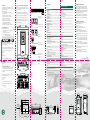
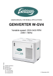
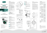
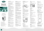
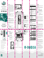
WhisperPower
Power Module Genverter
WP-PMG 4kW
When the Genverter is started, the control panel LEDs will provide
various types of operating information:
Control panel information
AC Load
A series of five LEDs showing the
WP-PMG’s approximate output voltage.
In a range from 210V to 250V, the 220V or 230V
LED will typically light up.
AC Voltage
Use of this manual
This manual serves as a guideline for safe and effective installation,
as well as correct operation, maintenance and, if necessary,
troubleshooting of the WP-PMG.
It is recommended to keep the manual in good condition for future
use. It should be kept in a dry and clean place, and available any
time.
WP-PMG 4kW
Pure sine wave from
your generator
Operation
The local control panel
power switch offers (apart
from the “Off“ mode) two
working modes: “On” and
“Remote”.
Select the “On“ position to enable both the WPPMG and the Genverter.
With the switch in the “Remote” position, the WPPMG can be operated by means of the remote
panel (as presented above). In other words, the
unit can be switched on and off both from the
remote panel and on the unit itself.
General precautions
To ensure safe and sustainable operation of the WP-PMG, the
handling and safety instructions detailed in this manual shall be
followed at all times. Every person working on or with the WP-PMG
should be familiar with the contents of this document. Also bear in
mind that all applicable (safety) standards and (local) regulations
shall be followed at all times.
Furthermore, only qualified and authorized technical experts are
permitted to perform maintenance activities which require opening
the system.
IMPORTANT!
Throughout this manual, the following alert symbol is used
to indicate potential hazard:
CAUTION / WARNING!
Risk of equipment damage or personal injury. Always
be aware that your actions may have an impact on
safety and/or on product performance.
Carefully follow instructions documented.
Alerts
Series of four LEDs alerting in case of:
- inverter failure
- high oil pressure
- high oil temperature
- high exhaust temperature
Runtime
Series of three LEDs indicating the WP-PMG
runtime since last maintenance.
Problem Possible cause
Inverter failure Ventilation is blocked
LED
illuminated
AC input is
out of range
Oil pressure
LED
illuminated
Oil temperature LED
illuminated
L1
L2
INPUT
L3
PE
PE
L1
OUTPUT
N
Solution
Move the WP-PMG to
Ambient temperature is
a colder position, or
too high
reduce the load
Use the “START“ and
“STOP“ buttons simultaneously to be able to reset
the runtime measurement
functionality (indicating
when next maintenance is
due).
1 2 3 4 5
When LED “210V/WAIT“ is blinking, the system wait
for a user command.
When LED “220V/TILL“ is blinking, the generator is
in Till mode.
When LED “210/WAIT“ is blinking, the engine is
cranking.
3. Troubleshooting
The table below lists possible failure conditions. If the failure LED
illuminates, switch off the WP-PMG, adopt the applicable solution(s)
and switch the WP-PMG on again.
Once the WP-PMG has
been switched “On“, use the
“START“ and “STOP“ button
to switch the Genverter on
and off.
Note: press and hold
for 2 seconds !
2. Instructions for Use
CAUTION ! Risk of fire, electric shock
and/or equipment damage
-The WP-PMG was designed for
dry and clean environments.
-Do not expose it to dust, rain,
snow or liquids of any type.
-Do not smoke near the WP-PMG.
-To prevent overheating, DO NOT block ventilation.
-Do not place any inflammable
materials near the WP-PMG.
-Verify the condition and connection of all
cables on a regular basis.
- Excellent choice to replace traditional gensets
- 4kW continuous 230V power from
your variable speed generator system
- High efficiency and strong peak power
- Outstanding voltage stability
- Saving fuel and ensuring smooth
running of your genset
- Genverter Power, the best choice
for your energy supply
A series of five LEDs showing the
WP-PMG’s output as a percentage of its rated
output. If all five LEDs start blinking, the WP-PMG
is overloaded and may shut down at any moment.
- - + +
Exhaust temperature LED
illuminated
Improve ventilation
Check generator output
voltage and frequency,
and correct if necessary
Too many or too
heavy AC consumers
Reduce the load
Oil leakage
Contact WhisperPower
Service centre
Oil level too low
Refill
Insufficient cooling
Check coolant pump;
replace impeller and/or
gasket if necessary
Load too high
Reduce load
Too rich fuel
Contact WhisperPower
Service centre
4. Installation
General Remarks
Local and/or special regulations may apply depending on the type of
installation involved.
It is essential that each and every circuit in the electrical system
is properly installed by a qualified electrician using all applicable
standards.
CAUTION !
Risk of electric shock, personal injury,
explosion and/or equipment damage
-Do not work on the WP-PMG or the electrical
installation while it is still connected to a power
source.
-Never connect the inverter output to a 230V
connection of the public grid.
-All electrical safety/shutdown and circuit breaking
systems have to be installed separate from the
WP-PMG.
In Europe, pleasure craft smaller than 24 meter is subject to the EC
Recreational Craft Directive, which refers to EN ISO 13297:2012
(Small craft - Electrical systems - Alternating current installations).
When installing a 230V system on a vehicle, be aware that people
are not used to having such systems on a vehicle. Put warning signs
on wall sockets and on junction boxes. Instruct non-regular users of
the vehicle. Warn maintenance personnel of garages servicing the
vehicle.
Grounding
The housings of the Genverter and of the WP-PMG are grounded
by means of the green/yellow wires in the Genverter and output
cables. Making a connection between “neutral” and “ground” of the
AC 230V output could be necessary as part of a specific insulation
failure protection system. This should only be done by experts when
installing such a system.
For vehicles, methods of protection are subject to rules that may
vary depending on the use of the vehicle and local standards.
Experts in this field should be consulted.
Transfer Switching
When a connection to the public grid is required, a power source
selector must be installed between the WP-PMG and the vessel’s/
vehicle’s electrical system. This so-called transfer switch is an
essential safety device allowing all AC consumers to be switched off
simultaneously and separating the WP-PMG output from the grid.
WhisperPower recommends the installation of a WP AC Transfer
System Switch. By default, this uses grid input. When it detects
WP-PMG input, it automatically switches over to generator input
after 10 seconds delay time. Even more advanced, a WP WhisperSwitch allows simultaneous input from the Genverter and the grid.
Refer to the applicable product instructions.
Location
When looking for a proper position for installing the WP-PMG, all
relevant aspects have to be taken into account, in particular:
- The WP-PMG must be installed in a dry and clean place protected
from strong vibrations. Do not expose the WP-PMG to dust, rain,
snow or liquids of any type. The input being three-phase alternating current, the WP-PMG can be installed at some distance
from the Genverter.
- Ensure that ventilation airflow is not obstructed in any way. Keep
a free space of 200 mm around the unit.
- The unit’s control panel must remain accessible.
- The WP-PMG contains components capable of producing arcs
or sparks. To prevent fire or explosion, do not install the unit in
compartments containing batteries or flammable materials or in
locations requiring ignition protected equipment. Moreover, gases
from batteries will corrode and damage the WP-PMG.
WhisperPower BV
Kelvinlaan 82, 9207 JB Drachten, The Netherlands
Tel: +31 (0) 512 571 550, Fax: +31 (0) 512 571 599
[email protected], www.whisperpower.com
20141211Manual WP-PMG 4kW
USER MANUAL
1. Introduction
Thanks for choosing our product. The Power Module for Genverter
(WP-PMG) is an essential link between your WhisperPower
Genverter and your AC electrical system. WhisperPower Genverters
are state-of-the-art systems using very compact and highly efficient
Permanent Magnet alternators to produce electric power. Unlike
traditional fixed speed generator sets, however, Genverters may
produce output voltages up to 350VAC with frequencies as high as
400Hz. This is where the WP-PMG comes into play, using advanced
power electronics to produce a stable sinusoidal AC voltage at 50Hz,
as required by regular 230V appliances. Safety is enhanced by
WP-PMG’s capability to blow fuses when a short-circuit occurs.
5. Specifications
STEP 4: Connecting the remote control panel (optional)
The WP-PMG has a local control panel, which is on the unit,
and a remote control panel, the installation of which is optional
(marine version shown).
List of Materials
The delivery includes the WP-PMG and a WhisperPower remote
control panel with its 5 m RJ12 connecting cable. 10 m and 15 m
cables are available on request.
Additional materials required:
- Screws / bolts (4 × Ø 6 mm, with plugs if necessary)
to mount the unit to a wall.
- A sufficient number of short-circuit proof clamps.
- Cable lugs (7) for connecting the various 4 mm2 wires.
- Cable ties , for securing the input and output
cables (at least 4, e.g. 140 mm × 3.5 mm).
- An output cable, i.e. any cable of appropriate rating
and length to accommodate the application.
- A slow-reacting output fuse (32A recommended).
- If another 230V source may be available, a transfer switch.
The remote control panel can be mounted either on or in the
dashboard. When the remote control is mounted on the dashboard, the back cover can be used as a drill template.
The ports above
are configured as follows:
The connecting cable can exit in any direction through one of
pre-shaped ports in the sides of the plastic case or through a
hole in the dashboard. On the WP-PMG, the cable is plugged
into the PMG REMOTE port.
RJ12 port for remote control
RJ12 port for external remote
STEP 1: Mounting the unit
- Determine the bolt / screw positions.
- Turn the screws / bolts (Ø 6mm) into the wall but do not
tighten them entirely.
- Place the housing over the screws / bolts.
- Fix the housing by fastening the screws securely.
RJ45 port
for CAN bus connection
STEP 2: Connecting the Genverter cable
The Genverter cable (e.g. 4 × 6 mm2) shall be installed using
short-circuit proof clamps.
USB Type 2 port
for setting output parameters
Remove the cover protecting the terminals by unscrewing the
two tapping screws. Provide the Genverter cable wires with lugs
and connect the wires to the input terminals as follows:
brown to L1;
black to L2,
grey to L3,
green/yellow to PE.
Morsetti Faston contacts
(6.3mm, 90 MFB0605)
for analog controls
1 – COMM
2 – ON STATUS
(NO)
3 – ERR STATUS
(NO)
4 – INPUT
5 – GND
Use cable ties of sufficient strength as a strain relief.
Connect the 5-pin motor control cable to the motor control
connector.
177
164
STEP 3: Connecting the output cable
A slow-reacting fuse (32 A recommended) should be installed
to protect the installed electrical system. Make sure there is a
Residual Current Device between the WP-PMG and any on board
AC equipment.
100 100
450
Power module for genverter 4kW
60201404
GENERAL SPECIFICATIONS
Genverter model
Output load
Output voltage
Output voltage stability
Output frequency
Frequency variations
Output current
Nominal apparent power
Continuous power (cos phi = 1)
Peak power (15 min.)
Nominal efficiency (@ full load)
Peak efficiency
Input voltage
Input frequency
Max. input current
Weight
Dimensions (h × w × d)
Mounting rectangle (h × w)
Genverter 4
True sine
200 .. 240 VAC (nominal 230V)
+/- 5% (resistive load step 0 .. 100%)
45 .. 55 Hz (nominal 50Hz)
< 1%
36A
3500VA
3500W
4kW
95%
97%
3 times 220 .. 350VAC
200 .. 400Hz
17A
5kg
436 × 196 × 148mm
412 × 100mm
TECHNICAL SPECIFICATIONS
Voltage THD (Total Harmonic Distortion)
Short circuit protection
Mean time between failure
Lifetime expectancy (@ 40°C and nominal load)
< 3%
yes
10 years
100.000 hours
Local read out module
Inverter status load bar, voltage and runtime (for maintenance purposes)
indicator and failure detection notification
Remote panel (LED)
Inverter status load bar, voltage indicator, AC input present and failure
detection notification
USB
Potentional-free status contact
Wire system
Recommended cable cross input / protection fuse
Recommended cable cross output / protection fuse
Remote panel connection
Engine interface connection
For software parameter configuration
Inverter enabled / disabled
L1 - N - PE
4mm / 32A
4mm / 32A RCD
RJ12 twisted cable
Engine RPM request (pwm signal; optimal)
CONDITIONS
Operating temperature
Storage temperature
Relative humidity in operation/storage
Protection degree
Ventilation
-20 .. 70°C (linear derating above 40°C)
-40 .. 80°C
Max. 95% non-condensing
IP23
Forced cooling (non-dependent)
7. CE manufacturer’s declaration
We, WhisperPower BV, Kelvinlaan 82, 9207 JB Drachten,
Netherlands, hereby declare that:
Product: 60201404
WhisperPower-Power Module Genverter
Is in conformity with the following provisions of the EC:
2004/108/EC (EMC Directive),
the following harmonized standards having been applied:
- EN 55022:2010 (Information technology equipment - Radio
disturbance characteristics - Limits and methods of measurement)
- EN 61000-3-2:2006 (Electromagnetic compatibility [EMC]
- Part 3-2: Limits - Limits for harmonic current emissions)
- EN 61000-6-1: 2007 (Electromagnetic compatibility [EMC],
Generic standards. Immunity for residential, commercial and
light-industrial environments)
- EN 61000-6-2: 2007 (Electromagnetic compatibility [EMC]
- Part 6-2: Generic standards - Immunity for industrial environments)
- EN 60945:2002 (Maritime navigation and radiocommunication
equipment and systems)
2006/95/EC (Low Voltage Directive), the following harmonized
standard having been applied:
- EN 60950: 2000 (Safety of information technology equipment)
Drachten,
M. Favot, C.T.O. WhisperPower B.V.ww
COMPLIANCE
450
Directives: EMC 2004/108/EC, LVD 2006/95/EC
600
8x 7
Standards:
M8 x 1.0 - 6H
560
trough
all
EN 55022 (emission), EN 61000-3-2 (harmonics),
EN 61000-4-11,
EN 61000-6-1, EN
61000-6-2 (immunity), EN 60945 (maritime navigation and
radiocommunication), EN 60950 (safety)
460
461
461
520
197 197
20
60
472
472
472
197
8 x 7 THRU
M8 x 1.0 - 6H THRU
360
400
520
462
462
490
490
462
R20
490
Provide the output cable wires with lugs and connect the wires
to the output terminals as follows:
green/yellow to PE,
brown to L1,
blue to N.
Use cable ties of sufficient strength as a strain relief.
177 177
164 164 100
Article nr.
6. Warranty terms and conditions
WhisperPower guarantees that the equipment has been built
according to the legally applicable standards and specifications.
WhisperPower assures the product warranty of the Power Module
for Genverter during two years after purchase, on the condition that
all instructions and warnings given in this manual are taken into
account during installation and operation.
The warranty is limited to the costs of repair and/or replacement
of the product by WhisperPower only. Costs for installation labor or
shipping of the defective parts are not covered by this warranty.
Replace the cover protecting the terminals and tighten
the tapping screws.
120
20
458
480
Mounting dimensions remote panel
Front view remote panel
196
Bottom view WP-PMG
Front and side view WP-PMG
436
22
148
8
22
100
420
7,4
160
Rear and side view remote panel
22
8
100 100
436
100
4.5 4.5
8
55
3,5 (2x) 3,5 (2x)
3,5 (2x)
4.5
420
144 144
130 130
196
148
55
144
130
55
40
130 130
122 122
112 112
160
R5 (4x) R5 (4x)
R5 (4x)
130
122
112
7,4
100
40
458
480