1
USER MANUAL
Whisper Power Center
Unit combining inverter, battery charger
and transfer system.
Art.nr. 40200871
WHISPER POWER BV
Kelvinlaan 82
9207 JB Drachten
Netherlands
Tel.: +31-512-571550
Fax.: +31-512-571599
www.whisperpower.eu
V5 July 2012
TABLE OF CONTENTS
1
2
3
4
5
6
2
TABLE OF CONTENTS
INTRODUCTION ...................................................................................................................................... 4
GENERAL INFORMATION ....................................................................................................................... 4
2.1
Operating instructions ............................................................................................................................ 4
2.2
Conventions ............................................................................................................................................ 4
2.3
Quality and warranty .............................................................................................................................. 5
2.3.1 Exclusion of warranty ........................................................................................................................ 5
2.3.2 Exclusion of liability ........................................................................................................................... 5
2.4
Warnings and notes ............................................................................................................................... 5
2.4.1 General ............................................................................................................................................... 5
2.4.2 Precautions for using the batteries ................................................................................................... 6
ASSEMBLY AND INSTALLATION ............................................................................................................. 7
3.1
Handling and moving ............................................................................................................................. 7
3.2
Storage .................................................................................................................................................... 7
3.3
Unpacking ............................................................................................................................................... 7
3.4
Installation site ........................................................................................................................................ 7
3.5
Fastening ................................................................................................................................................ 7
3.5.1 Fastening ............................................................................................................................................ 8
3.6
Connections ............................................................................................................................................ 8
3.6.1 General recommendations ................................................................................................................ 8
3.6.2 Device connection compartment ...................................................................................................... 9
3.6.3 Dipswitch functions .......................................................................................................................... 11
CABLING .............................................................................................................................................. 12
4.1
Choice of system .................................................................................................................................. 12
4.1.1 Hybrid type stand-alone systems ................................................................................................... 12
4.1.2 Grid-connected emergency systems .............................................................................................. 12
4.1.3 Integrated mobile systems .............................................................................................................. 12
4.1.4 Multi-unit systems ............................................................................................................................ 12
4.1.5 Distributed Minigrid: ......................................................................................................................... 12
4.2
Earthing system .................................................................................................................................... 13
4.2.1 Mobile installation or installation connected to the grid via plug connector ................................. 13
4.2.2 Stationary installation ...................................................................................................................... 13
4.2.3 Installation with automatic PE-neutral switching ........................................................................... 14
4.2.4 Lightning protection ......................................................................................................................... 14
4.3
Recommendations for dimensioning the system ............................................................................... 14
4.3.1 Dimensioning the battery ................................................................................................................ 14
4.3.2 Dimensioning the inverter ............................................................................................................... 14
4.3.3 Dimensioning the generator ............................................................................................................ 15
4.3.4 Dimensioning the renewable energy sources ................................................................................ 15
4.4
Wiring diagrams.................................................................................................................................... 15
4.5
Connecting the battery ......................................................................................................................... 15
4.5.1 Battery cable cross-section and DC protective devices ................................................................ 16
4.5.2 Connecting the battery (WPC side) ................................................................................................ 17
4.5.3 Fuse mounting on battery positive pole ......................................................................................... 17
4.5.4 Battery-side connection ................................................................................................................... 17
4.5.5 Earthing the battery ......................................................................................................................... 18
4.5.6 Connecting the consumers at the 230V AC outputs ..................................................................... 18
4.5.7 Connecting the AC supply sources ................................................................................................ 19
4.5.8 Connecting the communications cables ........................................................................................ 19
4.5.9 Connecting the auto-start cable ...................................................................................................... 19
4.5.10
Connecting the temperature sensor (BTS-01) .......................................................................... 19
POWERING UP THE INSTALLATION ...................................................................................................... 19
DESCRIPTION AND FUNCTIONING ..................................................................................................... 20
6.1
Circuit diagram ..................................................................................................................................... 20
6.2
Description of the main functions ........................................................................................................ 21
6.2.1 Inverter ............................................................................................................................................. 21
6.2.2 Automatic load detection ................................................................................................................. 21
July 2012 / WPC / EN
TABLE OF CONTENTS
6.2.3 Transfer relay ................................................................................................................................... 21
6.2.4 Battery charger ................................................................................................................................ 23
6.2.5 Battery protection ............................................................................................................................. 25
6.2.6 WPC protection ................................................................................................................................ 25
7
MULTI-UNIT CONFIGURATION ............................................................................................................. 26
7.1.1 Three-phase system ........................................................................................................................ 26
7.1.2 Increasing the power by paralleling units ....................................................................................... 26
7.1.3 Combined system ............................................................................................................................ 26
7.1.4 Enlargement of an existing installation........................................................................................... 26
7.2
Accessories .......................................................................................................................................... 27
7.2.1 Control centre and display WPC-RCC/PSCP (remote control) .................................................... 27
7.2.2 BTS-01 temperature sensor............................................................................................................ 28
8
CONTROL ............................................................................................................................................. 29
8.1
Display and control panel .................................................................................................................... 29
9
MAINTENANCE OF THE INSTALLATION ............................................................................................... 31
10 PRODUCT RECYCLING ......................................................................................................................... 32
11 EC DECLARATION OF CONFORMITY .................................................................................................. 33
12 CONTROL AND DISPLAY PARTS FOR THE WPC (FIG. 4B) ................................................................... 34
13 TABLE OF FACTORY’S (DEFAULTS) PARAMETERS SETTINGS ............................................................... 35
14 TECHNICAL DATA – WPC .................................................................................................................... 37
14 TECHNICAL DATA – WPC .................................................................................................................... 37
14.1
dimensions ........................................................................................................................................... 38
14.2
type plate ............................................................................................................................................ 39
15 NOTES ................................................................................................................................................... 40
July 2012 / WPC / EN
3
INTRODUCTION
1 INTRODUCTION
Congratulations! You are about to install and use a device from the Whisper Power Centre range. You have
chosen a high-tech device that will play a central role in energy saving for your electrical installation. The
WPC has been designed to work as an inverter / charger with advanced functions, which can be used in a
completely modular way and guarantee the faultless functioning of your energy system.
When the WPC is connected to a generator or grid, the latter directly supplies the consumers, and the WPC
works like a battery charger and backup device if necessary. The powerful battery charger has an
exceptional high efficiency and power factor correction (PFC) close to 1. It guarantees excellent battery
charging in all situations. The charge profile is freely configurable according to the type of battery used or the
method of usage. The charge voltage is corrected depending on the temperature, thanks to the optional
external sensor. The power of the charger is modulated in real time dependent according to the demand of
the equipment connected at the WPC output and the power of the energy source (grid or generator). It can
even temporarily backup the source if the consumer demand exceeds the source capacity.
The WPC continuously monitors the source to which it is connected (grid or generator) and disconnects itself
immediately if the source is missing, disturbed or does not correspond to the quality criteria (voltage,
frequency, etc.). It will then function in independent mode, thanks to the integrated inverter. This inverter,
which has an extremely robust design, benefits from WhisperPower’s many years of experience and
expertise in this area. It could supply any type of load without faults, enjoying reserves of additional power
that is unmatched on the market. All your equipment will be perfectly provided with energy and protected
from power outages in systems where energy supply is unpredictable (unreliable grid) or voluntarily limited or
interrupted, such as hybrid installations on remote sites or mobile installations.
The parallel and/or three-phase grid operation of the WPC offers modularity and flexibility and enables
optimum adaptation of your system to your energy requirements.
The WPC-RCC/PSCP control, display and programming centre enables optimum parametering of the
system and guarantees the operator continuous control for all important parameters in the installation.
In order to guarantee perfect commissioning and functioning of your installation, please read this manual
carefully. It contains all the necessary information relating to the functioning of the inverters / chargers in the
WPC series. The setting up of such a system requires special expertise and may only be carried out by
qualified personnel familiar with the applicable local regulations.
2 GENERAL INFORMATION
2.1 OPERATING INSTRUCTIONS
This manual is an integral part of each inverter/charger from the WPC series.
It covers the following models and accessories:
Inverter/charger: WPC 2000-12, WPC 3500-24, WPC 4000-48
Temperature sensor: WPC-BTS-01
Remote command module: WPC-RCC, WPC-PSCP
For greater clarity, the device is referred to in this manual as WPC, unit or device, when the description of its
functioning applies indiscriminately to different WPC models.
These operating instructions serve as a guideline for the safe and efficient usage of the WPC. Anyone who
installs or uses a WPC can rely completely on these operating instructions, and is bound to observe all the
safety instructions and indications contained. The installation and commissioning of the WPC must be
entrusted to a qualified professional. The installation and usage must conform to the local safety instructions
and applicable standards in the country concerned.
2.2 CONVENTIONS
This symbol is used to indicate the presence of a dangerous voltage that is sufficient to constitute
a risk of electric shock.
This symbol is used to indicate a risk of material damage.
This symbol is used to indicate information that is important or which serves to optimise your
system.
4
July 2012 / WPC / EN
GENERAL INFORMATION
All values mentioned hereafter, followed by a parameter number indicate that this value may be modified
using the WPC remote control.
In general, the default values are not mentioned and are replaced by a parameter number in the following
format: {xxxx}. The default values for this parameter are specified in the defaults parameter table, p. 35.
All parameter values modified by the operator or installer must be transferred into the same table.
If a parameter not appearing in the list (advanced parameters) has been modified by an
authorised person with technical knowledge, they will indicate the number of the modified
parameter(s), the specifications of the parameter(s) and the new value set, at the end of the same
table.
All figures and letters indicated in brackets or in square brackets refer to items that can be found in the
separate manual “Appendix to the installation and operating instructions” supplied with the device. In this
appendix, these figures and letters are encircled.
The figures in brackets refer to elements belonging to the WPC.
The uppercase letters in brackets refer to AC cabling elements.
The lowercase letters in brackets refer to battery cabling elements.
2.3 QUALITY AND WARRANTY
During the production and assembly of the WPC, each unit undergoes several checks and tests. These are
carried out with strict adherence to the established procedures. Each WPC has a serial number allowing
complete follow-up on the checks, according to the particular data for each device. For this reason it is very
important never to remove the type plate which shows the serial number. The manufacture, assembly and
tests for each WPC are carried out in their entirety by our factory in Drachten (the Netherlands). The
warranty for this equipment depends upon the strict application of the instructions appearing in this manual.
The warranty period for the Whisper Power Centre is 2 years.
2.3.1 Exclusion of warranty
No warranty claims will be accepted for damage resulting from handling, usage or processing that does not
explicitly appear in this manual. Cases of damage arising from the following causes are notably excluded
from the warranty:
Surge voltage on the battery input (for example, 48 V on the battery input of an WPC 2000-12)
Incorrect polarity of the battery
The accidental ingress of liquids into the device or oxidation resulting from condensation
Damage resulting from falls or mechanical shocks
Modifications carried out without the explicit authorisation of WhisperPower
Nuts or screws that have not been tightened sufficiently during the installation or maintenance
Damage due to atmospheric surge voltage (lightning)
Damage due to inappropriate transportation or packaging
Disappearance of original marking elements
2.3.2 Exclusion of liability
The placement, commissioning, use, maintenance and servicing of the WPC cannot be the subject of
monitoring by WhisperPower. For this reasons we assume no responsibility and liability for damage, costs or
losses resulting from an installation that does not conform to the instructions, defective functioning or
deficient maintenance. The use of a WhisperPower inverter is the responsibility of the customer in all cases.
This equipment is neither designed nor guaranteed to supply installations used for vital medical care nor any
other critical installation carrying significant potential damage risks to people or the environment.
We assume no responsibility for the infringement of patent rights or other rights of third parties that result
from using the inverter.
WhisperPower reserves the right to make any modifications to the product without prior notification.
2.4 WARNINGS AND NOTES
2.4.1 General
July 2012 / WPC / EN
5
GENERAL INFORMATION
This manual is an integral part of the device and must be kept available for the operator and
installer. It must remain close to the installation so that it may be consulted at any time.
The parameter table available at the end of the manual (p. 35) must be kept up to date in the event of
modification of the parameters by the operator or installer. The person in charge of installation and
commissioning must be wholly familiar with the precautionary measures and the local applicable regulations.
When the WPC is running, it generates voltage that can be potentially lethal. Work on or close to
the installation must only be carried out by thoroughly trained and qualified personnel. Do not
attempt to carry out ongoing maintenance of this product yourself. The WPC or the generator
connected to it may start up automatically under certain predetermined conditions.
When working on the electrical installation, it is important to be certain that the source of DC
voltage coming from the battery as well as the source of AC voltage coming from a generator or
grid have been disconnected from the electrical installation.
Even when the WPC has been disconnected from the supply sources (AC and DC), a dangerous
voltage may remain at the outputs. To eliminate this risk you must switch the WPC OFF using the
ON/OFF button (1). After 10 seconds the electronics is discharged and intervention may take
place without any danger.
All elements connected to the WPC must comply with the applicable laws and regulations.
Persons not holding written authorisation from WhisperPower are not permitted to proceed with any change,
modification or repairs that may be required. Only original parts may be used for authorised modifications or
replacements.
This manual contains important safety information. Read the safety and working instructions carefully before
using the WPC. Adhere to all the warnings given on the device as well as in the manual, by following all the
instructions with regard to operation and use.
The WPC is only designed for indoor use and must under no circumstances be subjected to rain, snow or
other humid or dusty conditions.
The maximum specifications of the device shown on the type plate, as at fig. 1b, must be adhered to.
In the event of use in motorised vehicles, the WPC must be protected from dust, splash water and any other
humid condition. It must also be protected from vibration by installing absorbent parts.
2.4.2 Precautions for using the batteries
Lead-acid or gel batteries produce a highly explosive gas with normal use. No source of sparks or fire should
be present in the immediate vicinity of the batteries. The batteries must be kept in a well-ventilated place and
be installed in such a way as to avoid accidental short-circuits when connecting.
Never try to charge frozen batteries.
When working with the batteries, a second person must be present in order to lend assistance in the event of
problems.
Sufficient fresh water and soap must be kept to hand to allow adequate and immediate washing of the skin
or eyes affected by accidental contact with the acid.
In the event of accidental contact of the eyes with acid, they must be washed carefully with cold water for 15
minutes. Then immediately consult a doctor.
Battery acid can be neutralised with baking soda. A sufficient quantity of baking soda must be available for
this purpose.
Particular care is required when working close to the batteries with metal tools. Tools such as screwdrivers,
open-ended spanners, etc. may cause short-circuits. Consequently occurring sparks may cause the battery
to explode.
When working with the batteries, all metal jewellery such as rings, bracelet watches, earrings, etc., must be
taken off. The current output by the batteries during a short-circuit is sufficiently powerful to melt the metal
and cause severe burns.
In all cases, the instructions of the battery manufacturer must be followed carefully.
6
July 2012 / WPC / EN
ASSEMBLY AND INSTALLATION
3 ASSEMBLY AND INSTALLATION
3.1 HANDLING AND MOVING
The weight of the WPC is between 35 and 50kg depending upon the model. Use an appropriate lifting
method as well as help from a third party when installing the equipment.
3.2 STORAGE
The equipment must be stored in a dry environment at an ambient temperature of between
-20°C and 60°C. It stays in the location where it is to be used a minimum of 24 hours before being set up.
3.3 UNPACKING
When unpacking, check that the equipment has not been damaged during transportation and that all
accessories listed below are present. Any fault must be indicated immediately to the product distributor or the
contact given at the back of this manual.
Check the packaging and the WPC carefully.
Standard accessories:
Installation and operating instructions, c.f. Appendix 1
Mounting plate – fig. 2a (18)
Cable gland
3.4 INSTALLATION SITE
The installation site for the WPC is of particular importance and must satisfy the following criteria:
Protected from any unauthorised person.
Protected from water and dust and in a place with no condensation.
It must not be situated directly above the battery or in a cabinet with it.
No easily inflammable material should be placed directly underneath or close to the WPC.
Ventilation apertures must always remain clear and be at least 20cm from any obstacle that may
affect the ventilation of the equipment.
In mobile applications it is important to select an installation site that ensures as low a vibration level
as possible.
3.5 FASTENING
The WPC is a heavy unit and must be mounted to a wall designed to bear such a load. A simple
wooden panel is insufficient.
July 2012 / WPC / EN
7
ASSEMBLY AND INSTALLATION
The WPC must be installed vertically with sufficient space around it to guarantee adequate ventilation of the
device.
3.5.1 Fastening
Screw on a solid wall (concrete or metallic wall) the supplied
mounting washer using a suitable bolt.
Hang the WPC unit on the wall using the upper bracket on the
backside of the WPC. Make sure that the bracket is securely fixed.
For mobile and marine applications it is also necessary to fix the unit
using the bottom mount. Use two bolts to secure the bottom mount
to the wall.
It is imperative to ensure complete and safe fastening of
the device. A device that is simply hung may detach and
cause severe damage.
In motor vehicles or when the support may be subject to strong
vibrations, the WPC must be mounted on anti-vibration supports.
3.6 CONNECTIONS
3.6.1 General recommendations
The WPC falls within protection class I (has a PE connection terminal). It is vital that a protective earth is
connected to the AC IN and/or AC OUT PE terminals. An additional protective earth is located between the
two fastening screws at the bottom of the unit (17).
In all cases, the PE conductor for the equipment must at least be connected to the PE for all
equipment in protection class I upstream and downstream of the WPC (equipotential bonding). It
is mandatory that the legislation in force for the application concerned be adhered to.
8
July 2012 / WPC / EN
ASSEMBLY AND INSTALLATION
Tighten of the input (13) and output (14) terminals by means of a no. 3 screwdriver.
The cable sections of these terminals must conform to local regulations.
All connection cables as well as the battery cables must be mounted using cable restraints in order to avoid
any traction on the connection.
Battery cables must also be as short as possible and the section must conform with the applicable
regulations and standards. Sufficiently tighten the clamps on the “battery” inputs (11) and (12).
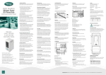
3.6.2 Device connection compartment
The unit’s connection compartment must remain permanently closed when in operation. It is
imperative to close the protection cap on the connection terminals after each intervention in the
device.
After opening, check that all sources of AC and DC voltage (batteries) have been disconnected
or put out of service.
10
10
11
10
12
10
13
10
July 2012 / WPC / EN
15
10
16
14
10
10
9
ASSEMBLY AND INSTALLATION
1
2
3
4
17
10
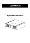
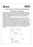
Pos. Denomination Description
1
Auto start
2
Temp. Sens
3
WPC bus
10
O/T
(Open /
Terminated)
L1/L2/L3
11
+BAT
12
-BAT
13
AC Input
Generator
14
AC Input Grid
15
AC Output
Gen/Grid/Inv
16
AC Output
Gen/Grid
4
17
10
Connector for connecting the
auto-start cable
Connector for the battery
temperature sensor
Double connector for connecting
peripherals such as the
RCC/PSCP or other WPC units
Switch for terminating the
communication bus.
Phase selection jumpers.
Positive pole battery connection
terminals
Negative pole battery connection
terminals
Connection terminals for the AC
generator
Connection terminals for the AC
grid
Connection terminals for the
device output. (Continuous)
Connection terminals for the
device output.(Only active when
AC input is present)
Protective earth
Comment
Refer to DDC and RCC/PSCP manual
See chapter 8.2.2 – p. 28.
Only connect the original WhisperPower
BTS-01 sensor
See chapter 4.5.8 – p. 19.
The two termination switches (4) for the
communication bus both remain in position T
(terminated) except when both connectors
are in use.
Jumper default at position L1
Carefully read chapter 4.5 – p.15
Take care with the polarity of the battery and
when tightening the clamp.
See chapter 4.5.7 - p. 19.
Note: It is imperative that the PE terminal be
connected.
See chapter 4.5.7 - p. 19.
Note: It is imperative that the PE terminal be
connected.
See chapter 4.5.6 - p. 19.
Note: Increased voltages may appear on the
terminals, even in the absence of voltage at
the input of the inverter.
See chapter 4.5.6 - p. 19.
Note: Increased voltages may appear on the
terminals, even in the absence of voltage at
the input of the inverter.
See chapter 3.6.1 – p. 8 and 4.2 p. 13
July 2012 / WPC / EN
ASSEMBLY AND INSTALLATION
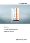
3.6.3 Dipswitch functions
To set the behavior of the input switching component of the WPC a dipswitch is available at the input
switching board. To access it, open the connection compartment cover. The figure below show the location
of the dipswitch.
Dipswitch location
Dipswitch
Function
Default
1
Prohibit automatic start when grid is available
Off
2
Preferred input ON = Generator
On
Off = Grid
3.6.3.1 Prohibit automatic start when grid is available
Default the generator will automatically start when one of auto start criteria is met. It starts even when the is
AC grid is connected. In some cases the AC grid can supply more power than the generator. In this situation
it is most likely that starting of the generator is not wanted. To prohibit the generator from starting in this
situation set the upper dipswitch to the “ON” position. Now the Autostart signal will indicate “start” only when
there is no grid available. Refer to the figure above for the position of the dipswitch.
3.6.3.2 Preferred input
When both AC inputs are available, this setting will determine which AC input is passed through for power
delivery.
July 2012 / WPC / EN
11
CABLING
4 CABLING
The connection of the WPC inverter / charger is an important installation step.
It may only be carried out by qualified personnel and in accordance with the applicable local regulations and
standards. The installation must always comply with these standards.
Pay attention that connections are completely tightened and that each wire is connected at the right place.
4.1 CHOICE OF SYSTEM
The WPC may be used in different system types, each of which must meet the standards and particular
requirements associated with the application or site of installation. Only an appropriately qualified installer
can advise you effectively on the applicable standards with regard to the various systems and the country
concerned.
4.1.1 Hybrid type stand-alone systems
The WPC can be used as a primary supply system for off-grid sites where a renewable energy source (solar
or hydraulic) is generally available and a generator is used as backup. In this case, batteries are generally
recharged by a supply source such as solar modules, wind power or small hydropower systems. These
supply sources must have their own voltage and/or current regulation system and are connected directly to
the battery.
When the energy supply is insufficient, a generator is used as a back-up energy source. This allows the
batteries to be recharged and direct supply to consumers via the WPC transfer relay.
4.1.2 Grid-connected emergency systems
The WPC can be used as an emergency system, also known as an uninterruptible power supply (UPS) –
enabling a reliable supply to a site connected to an unreliable grid. In the event of an interruption to the
energy supply from the public grid, the WPC, connected to a battery, substitutes the faulty source and
enables a support supply to the users connected downstream. These will be supplied as long as the energy
stored in the battery allows. The battery will quickly be recharged at the next reconnection to the public grid.
The use of the WPC as a UPS must be carried out by qualified personnel who have been checked
by the responsible local authorities. The diagrams in the appendix are given for information and as
a supplement. The applicable local standards and regulations must be adhered to.
4.1.3 Integrated mobile systems
These systems are meant to be temporarily connected to the grid and ensure the supply of the mobile
system when this is disconnected from the grid. The main applications are for boats, service vehicles and
leisure vehicles. For these purposes the WPC has a double AC input.
4.1.4 Multi-unit systems
Whatever system is selected, it is possible to realise systems composed of several units of the same type
and the same power output. Up to three WPC’s in parallel or three WPC’s forming a three-phase grid or
three times two or three WPC’s in parallel forming a three-phase / parallel grid, may be thus combined.
4.1.5 Distributed Minigrid:
The implementation of the WPC on top of a distributed minigrid (beyond the main building) requires special
care in choosing the distribution system.
WhisperPower recommends a TT distribution for the DC grid as well as for the AC grid.
The size of the grid increases greatly the exposure of the inverters to atmospheric overvoltages
and to non equipotentiality in the grid. This is particularly noticeable in the aerial distribution grids.
In this case a very special care must be taken to well implementing all protection measures of the
installation.
12
July 2012 / WPC / EN
CABLING
The IT system is not recommended for the distribution. This kind of distribution is most of the time
forbidden by the local laws. The achievement of low voltage electric system is always subject to
local laws and must imperatively be implemented and controlled by qualified and professionally
authorized staff. WhisperPower accepts no liability for damages due to non confirming installation
and to the lack of compliance with the local rules or with the recommendations of this manual.
4.2 EARTHING SYSTEM
The WPC is a protection class I unit, which is intended for cabling in a grid type TT, TN-S or TNC-S. The
earthing of the neutral conductor (E) is carried out at a sole installation point, upstream of the RCD circuit
breaker (D).
The WPC can be operated with any earthing system. In all cases it is imperative that the protective earth be
connected in compliance with the applicable standards and regulations. The information, notes,
recommendations and diagram mentioned in this manual are subject to local installation regulations in every
case. The installer is responsible for the conformity of the installation with the applicable local standards.
4.2.1 Mobile installation or installation connected to the grid via plug
connector
When the input of the device is connected directly to the grid via a plug, the length of the cable must not
exceed 2 m and the plug must remain accessible.
In the absence of voltage at the input, the neutral and live are interrupted, thereby guaranteeing complete
isolation and protection of the cabling upstream of the WPC.
The earthing system downstream of the WPC is determined by the upstream earthing system when the grid
is present. In the absence of the grid, the earthing system downstream of the inverter is in isolated mode.
The safety of the installation is guaranteed by the equipotential bonding.
The connection (link) between the neutrals (C) upstream and downstream of the WPC is not
permitted in this configuration.
This connection type guarantees the optimal continuity for supplying the WPC loads. The first isolation fault
will not lead to an interruption in the supply.
If the installation requires the use of a permanent isolation controller this would have to be de-activated when
the TT grid is present at the WPC input.
All sockets and protection class I devices connected downstream of the WPC must be properly
connected to the earth (earthed socket). The cabling rules above remain valid, including in
installations, in all cases where the WPC input is connected to the grid via a plug connector.
4.2.2 Stationary installation
The installation may be equivalent to a mobile installation (with interrupted neutral).
In a fixed installation where the neutral is connected to the earth at a single installation point upstream of the
WPC, it is permissible to carry out a connection of the neutrals in order to preserve an unchanged earthing
system downstream, independent of the operating mode of the WPC. This choice has the advantage of
keeping the protection devices downstream of the WPC. This connection can be executed according to the
next figure, or carried out by modifying the parameter {1486}
In this case the appearance of the first fault will lead to the installation stopping or the disconnection of the
protection devices upstream and/or downstream of the WPC.
Safety is guaranteed by the equipotential bonding and by any RCD circuit-breakers placed downstream.
This connection (C) is not permitted if a socket is installed upstream of the WPC.
July 2012 / WPC / EN
13
CABLING
4.2.3 Installation with automatic PE-neutral switching
In certain applications, it is desirable to keep the neutral upstream and downstream of the WPC separated
(C) while re-establishing the earthing system (TN-S, TT or TNC-S) in the absence of voltage at the input.
This functionality is forbidden by default by the parameter {1485}. This parameter can be modified by the
parameter {1485} via the WPC-RCC/PSCP remote control. This modification must be carried out possessing
technical knowledge, at the responsibility of the installer and in conformity with the applicable regulations and
standards.
The authorization of this function adherence to the requirements for an earth-neutral connection at the
source.
4.2.4 Lightning protection
As per the installation site, it is highly recommended to set a protection strategy to protect your installation
against lightning. The strategies depend on various parameters directly linked to each site and we
recommend therefore to deal very professionally with this issue.
The damages due to lightning are generating most of the time significant costs (full replacing of the
printed electronic board) and are not covered by WhisperPower’s warranty.
4.3 RECOMMENDATIONS FOR DIMENSIONING THE SYSTEM
4.3.1 Dimensioning the battery
The battery capacity is dimensioned according to the requirements of the user – that is 5 to 10 times its
average daily consumption. The discharge depth of the battery will therefore be limited and the service life of
the battery will be extended.
On the other hand, the WPC must have a battery capacity that is large enough to be able to take full
advantage of the performance of the equipment. The minimum capacity of the batteries (expressed in Ah) is
generally dimensioned in the following way: five times the rated power output of the WPC / the battery
voltage. For example, the model 3500W/24V must have a battery of a minimum capacity of 3500*5/24=730
Ah (C 10). Because of the inverter’s extreme overload capacity, it is often recommended that this value be
rounded up. An under-dimensioned battery may lead to an accidental and undesired stopping of the WPC in
the event of high instances of use. This stoppage will be due to a voltage that is insufficient on the battery,
subject to a strong discharge current.
The battery will be selected with regard to the greatest value resulting from the calculations set out above.
The battery capacity determines the adjustment of the parameter {1137} “battery charge current”. A value
between 0.1 and 0.2 x C batt. [Ah] (C10) enables an optimum charge to be guaranteed.
The method proposed below is strictly indicative and in no way constitutes a guarantee of perfect
dimensioning. The installer is solely responsible for good dimensioning and installation
4.3.2 Dimensioning the inverter
The inverter is dimensioned in such a way that the rated power output covers the power of all the consumers
14
July 2012 / WPC / EN
CABLING
which will be used at the same time. A dimensioning margin of 20 to 30% is recommended to guarantee that
the WPC will work well in an ambient temperature of more than 25 °C.
4.3.3 Dimensioning the generator
The power output of the generator must be the same or more than the average daily power. Optimally, it
should be once or twice times this power. Thanks to the Smart Boost function (see chap.1.1.1 p.25) it is not
necessary to over-dimension the generator. Indeed, the loads those are temporarily higher than the power of
the generator will be supplied by the inverter. Ideally it should not have a power output by phase that is less
than half of the power of the WPC(s) present at this phase.
The power available downstream of the inverter when the generator is working is the same as the
sum of the two powers if the Smart Boost function is activated. The sum of the currents is limited
to a maximum of 30A
4.3.4 Dimensioning the renewable energy sources
In a hybrid system, the alternative energy sources such as the solar generator, wind power and small
hydropower should, in principle, be dimensioned in such a way as to be able to cover the average daily
consumption.
4.4 WIRING DIAGRAMS
The diagrams shown in this document are subsidiary. The applicable local installation regulations
and standards must be adhered to.
The elements referred to with an uppercase letter denote the alternate current (AC) part.
The elements referred to with a lowercase letter denote the direct current (DC) part.
4.5 CONNECTING THE BATTERY
Lead batteries are usually available in 2 V, 6 V or 12 V block types. In the majority of cases, in order to
obtain an operating voltage that is correct for WPC usage, several batteries must be connected in series or
in parallel depending on the circumstances.
July 2012 / WPC / EN
15
CABLING
4.5.1 Battery cable cross-section and DC protective devices
16
July 2012 / WPC / EN
CABLING
The battery cables must be protected by one of the following measures in all cases:
- protection device (fuse) at each pole
- protection device (fuse) on the pole not connected to the earth
The battery cables must also be as short as possible.
It is always preferable to keep the cable at the negative pole of the battery as short as possible.
In order to avoid any further loss and protection redundancy. A protective device (f) must be installed as
close as possible to the battery and sized according to the below table.
Range
Battery side fuse
WPC-4000-48
200A
Section of
cable (<3m)
50mm2
WPC-3500-24
300A
70mm2
WPC-2000-12
300A
70mm2
The recommended cable cross-sections are valid for
lengths less than 3 m. beyond this length it is strongly
recommended oversize the battery cables.
For safety reasons, we recommend an annual check
on the tightness of all connections.
For mobile installation the connections should be
checked more frequently for tightness.
The cable lugs must be carefully fixed and
tightened sufficiently to guarantee minimum
loss. Insufficient tightening may cause
dangerous heating at the connection point.
4.5.2 Connecting the battery (WPC side)
Insert the cable glands supplied on the battery cable before tightening the cable lugs. Crimp the cable lugs
and fasten the cable gland on the device. Repeat this for the second battery cable. Fix the battery cables to
the appropriate connections „+ Battery “and „- Battery “. The M8 screws must be very well tightened.
You can insert, if required, a fuse directly on the positive connection to the battery following the below
procedure.
If cable glands are omitted or if there is no cable is inserted in the cable gland, there is a high risk
of penetrating of small animals inside the unit and a risk of damage not covered by warranty. Any
unused gable gland on the unit must be properly closed.
4.5.3 Fuse mounting on battery positive pole
A fuse delivered with the unit (WPC) can be mounted directly on the positive connecting pole to the battery
respecting the below stacking order.
The presence of this fuse does not exempt an installation of a protective device (fuse or circuit breaker) as
close as possible of the battery.
a = M10 cable lug
b = bolt M10 x 30
c = washer
d = ceramic washer
e = fuse
Be careful with the orientation of the ceramic washer. There is a small lip on one side which must
fit into the M10 cable lug’s hole.
4.5.4 Battery-side connection
Before connecting the battery, carefully check the voltage and polarity of the battery using a
voltmeter.
Incorrect polarity or over-voltage may seriously damage the device.
July 2012 / WPC / EN
17
CABLING
Prepare the batteries for connection: appropriate battery clamps, protection device (f), cable in good
conditions with correctly fitted clamps.
Fasten the negative cable on to the negative pole (-) of the battery and the positive cable on the open
protection device (f).
When connecting the battery, a spark may occur when connecting the second pole. This spark is
normal and due to the charging of the internal filtering capacitor of the WPC even if the unit is
halted by the main On/Off command (1).
As of the connection of the battery, it is necessary to check that the parameter values of the WPC
are consistent with the recommendations of the battery manufacturer. Non-conforming values
may be dangerous and/or seriously damage the batteries.
The default values of the battery’s charge threshold level are shown in fig. 3a and specified in the parameter
table p.35. If they are not acceptable when compared to the batterys manufacturer’s specification, it is
necessary to modify them via the remote control before connecting the voltage sources on the AC input
(charger). WhisperPower is not responsible for default values not corresponding with the recommendations
of the manufacturer.
If the factory settings are modified, the new values must be entered on the parameter table on p. 35
of this manual. The default values proposed by WhisperPower are the usual values for lead acid battery or
gel batteries (VRLA or AGM).
The cabling and connection of the installation should only be carried out by an appropriately qualified
professional. The installation material such as cables, connectors, distribution boxes, fuses, etc. must be
adapted and must conform to the applicable laws and regulations the application under consideration.
4.5.5 Earthing the battery
One of the two battery conductors can be earthed. This may be either the positive or negative pole. In all
cases the installation must conform to the local regulations and usage or specific standards associated with
the application.
In case of earthing, the earthing conductor section must at least be equivalent to the section of the battery
conductor. The earthing of the equipment must also adhere to these regulations. In this case the use of the
additional earthing screw is recommended (17), which is located at the front of the device between the two
lower fastening screws.
4.5.6 Connecting the consumers at the 230V AC outputs
High voltages may be present on the connection terminals (13) and (14). Make sure that the
inverter is deactivated and that there is no AC or DC voltage present on the AC IN terminals and
battery terminals, before proceeding with the connection.
The 230V consumers must be connected to the “AC OUT” (15) and (16) connection terminals with the wire
section conforming to the standards with regard to the rated current at the WPC output. Distribution must
conform to the local standards and regulations, and generally, be realised via a distribution table.
The WPC terminals are marked in the following way:
N = neutral, L = live
PE = protective earth (connected to the enclosure of the device).
Due to the source assistance function (Smart Boost) the current at the output of the device may
be higher than the rated current of the inverter. It is the sum of the current supplied by the
additional source and the current supplied by the inverter. In this case, the dimensioning of the
output cables will be carried out by adding the current indicated on the protection device (H)
located on the upstream of the unit, to the nominal current of the inverter. (See also chap. 1.1.1 –
p. 25)
If the assistance function at the source (Smart Boost) is not used, the size of the protection device for the
output (F) will be established at a maximum value equal to the rated current of the inverter, or at the
maximum value of the protection device at the input (H) if this is exceeds the rated current of the inverter.
18
July 2012 / WPC / EN
CABLING
An additional earthing terminal (17) is present between the two fastening screws at the bottom of
the unit. It can be used instead of a connection on the input terminals of the device, particularly
when cable cross-sections used at the output do not allow the use of a three-wire cable (live, earth
and neutral) through the conduit glands of the connection cables of the input and output (AC IN
and AC OUT), or when the earthing of one of the poles of the battery. PE required using same or
greater cross-sections than the battery cable.
4.5.7 Connecting the AC supply sources
The WPC is intended to be supplied by alternative voltage sources such as the public grid and/or a
generator. Check that the rated voltage of the source corresponds to the rated voltage (34) of the WPC
specified on the type plate (fig. 1b).
The source must be connected to the input terminals marked “AC INPUT” (13) with sufficient wire section,
depending on the power output of the source, and protected by a protection device of the appropriate calibre.
This will be at the maximum equal to the current I AC in max (35) specified on the type plate. The terminals
are marked in the following way:
N = neutral, L = live, PE = protective earth (connected to the enclosure of the device).
Any unused cable gland on the unit must be properly closed.
If not, there is a high risk of intrusion of small animals inside the unit and a risk of damage not
covered by warranty
4.5.8 Connecting the communications cables
The WPC is equipped with a pair of RJ45/8 connectors that allow information transfer via a communication
bus for different consumer types which have the proprietary protocol of WhisperPower. In this network all
parties in the network are connected in series (chain).
The length of the communication bus cable must not exceed 300 m.
In a system comprising a single WPC, the connection of the WPC remote control may be conducted without
stopping the WPC (hot plug).
The communication bus will be used to interconnect other WPC inverters in the case of a multi-unit
application or to connect other types of users who have the proprietary protocol of WhisperPower. In these
cases, the installation must be switched off using the main “ON/OFF” button (41) p. 29 to connect the units
via the communication bus.
The 2 switches for the communication bus termination, “WPC Bus" (4) both remain in position T
(terminated) except when both connectors are in use. In this case, and only in this case, both
must be placed in the O open position. If one of the two connectors is not in use, the two
termination switches (14) will be in position T.
4.5.9
Connecting the auto-start cable
The WPC is able to start the generator automatically when needed. To use this function the auto-start cable
has to be connected between the WPC (1) and the RCC/PSCP. (refer to RCC/PSCP manual)
4.5.10
Connecting the temperature sensor (BTS-01)
The temperature sensor, BTS-01 is supplied with a 3 m cable fitted with RJ11/6-type plugs. It may be
connected or disconnected at any time (including when the device is in use) using the corresponding socket
(2) marked “TS” on the WPC. Plug the connectors into the socket (2) until they click in. The temperature
sensor sleeve may simply be stuck onto the battery or directly next to it. The temperature sensor will be
recognised automatically and the correction made immediately.
5 POWERING UP THE INSTALLATION
It is imperative that the closing cap for the connection compartment be installed and screwed tight
before the installation is energised. There are dangerous voltages within the interior of the
connection compartment.
July 2012 / WPC / EN
19
DESCRIPTION AND FUNCTIONING
The Power up of the WPC must be carried out in the order given below. Any Power off must be carried out in
the reverse order.
A too high or inappropriate battery voltage may seriously damage the WPC. For example,
connecting a 24 V battery to the WPC 2000-12.
If the WPC has been connected the wrong way around by accident (incorrect polarity of the
battery) it is highly likely that the protection fuse on the battery cable may melt and will have to be
replaced. If such is the case, it will be necessary to disconnect all the connections to the WPC
including the battery. If, after replacing the fuse, the WPC proves not to work correctly after
reconnecting the battery with the correct polarity, it will have to be returned to your distributor for
repair.
Connecting the battery
The WPC is supplied and is ready for operation.
Connecting the consumers at the outputs.
Activate the output protection device (F) if existing, and/or press the ON/OFF button (41). The light indicator
“AC out” (46) lights up or flashes (in the event of an absence of consumers).
Activating the input circuit breaker(s) (H)
If an AC source (generator or electrical grid) valid in frequency and voltage is present at the AC input, the
device automatically goes into transfer and will start to charge the batteries. The consumers at the output are
therefore supplied directly by the power source present at the input.
Your installation is now in operation. If particular parameter or adjustment is required by the system, it is
recommended to carry this out immediately. Adjustments must be made with the WPC-RCC/PSCP remote
control. Please refer to the operating instructions for this accessory.
6 DESCRIPTION AND FUNCTIONING
6.1 CIRCUIT DIAGRAM
12V
20
July 2012 / WPC / EN
CONTROL
6.2 DESCRIPTION OF THE MAIN FUNCTIONS
6.2.1 Inverter
The WPC is equipped with a high-performance inverter which supplies a perfect and very precise sine wave.
Any unit designed for the 230 V/50 Hz electrical grid may connect to it without any problem, up to the rated
power out of your WPC. The inverter is protected against overloads and short-circuits.
Thanks to the largely over-dimensioned performance level, loads of up to three times greater than the WPC’s
rated output can be faultlessly supplied for short periods of use, thus allowing motors to be started up without
any problem.
When the WPC is operating the LED “ON” (43) is glowing.
When the WPC is in inverter mode, the LED “AC out” (46) is glowing. If it flashes, the inverter is in “load
search” mode (see following chapter “Automatic load detection”).
6.2.2 Automatic load detection
In order to save battery energy, the WPC inverter stops and automatically goes into load search when the
detected load is lower than the sensitivity set by the parameter {1187}. It automatically goes back into
operation when a power consumer greater than this value demands it. The indicator (46) flashes if the
inverter is in “load search” mode, which also indicates that the AC voltage is present at the output in an
intermittent form.
The detection threshold for the absence of loads can be adjusted according to the parameter range {1187}
by means of the WPC-PSCP / RCC remote control. When the parameter is set to 0 the inverter will still
operate even in the absence of any consumer.
In standby mode the system will thus consume minimal power from the battery (see table of technical data p.
36).
6.2.3 Transfer relay
The WPC can be connected to an alternative power source such as a generator or public grid. When the
voltage at the entry satisfies the voltage {1199 + 1470} and frequency {1505 - 1506} parameters, the transfer
relay will be activated after a delay {1528}. This delay may be adjusted(extended) to allow a fully stabile
status of the generator before transfer.
When the transfer relay is activated, the voltage present at the input of the WPC is available at the output for
the consumers connected. At the same time the battery charger goes into operation.
When the transfer relay of the WPC is active, the voltage at the output of the WPC is equivalent to
that which is present at the input and cannot be influenced or improved by the WPC. The
consumers are supplied by the source present at the “AC IN” input via the transfer relay.
The maximum current of the transfer relay is 30 A. This means that the permanent power of the consumers
must be a maximum of 11,500 W at 230 V (see chap. 1.1.1 p. 25). If the battery charger is in operation, part
of this power will be used for the battery charge.
The sharing of energy between consumers and the battery charger is adjusted automatically (see chap. 1.1.1
– p. 25). The transfer relay will be deactivated when the input voltage no longer satisfies the parameter
{1199} or {1432} min. and max. voltage and frequency at the input or when the current limit {1107} is
exceeded, if the exceeding of this limit is prohibited {1436} It then passes immediately into inverter mode. In
this case the loads are supplied exclusively by the battery via the inverter (see chap. 1.1.1 – p. 25). This
switching always takes place automatically. The presence of increased dynamic loads (such as pneumatic
angle grinders, etc.) may lead to an undesirable opening of the transfer relay due to the weakness of the
source. To this case, a delay in the opening of the transfer relay can be adjusted with the parameter {1198}.
When the generator stops, the change from transfer mode to inverter mode normally takes place without any
interruption of the output voltage . The interruption will be 40 ms in the event of the immediate loss of input
voltage at “AC IN” provided the UPS mode {1435} is not deactivated.
6.2.3.1 Type of detection of AC input loss (UPS)
When the WPC is connected to the public grid or to a generator supplying stable and clean AC voltage, the
type of detection of input loss {1552} can be selected to “fast”. In this mode, perturbation or lack of voltage of
less than 1 millisecond can be detected, switching the unit in inverter mode immediately.. This mode
guarantees a zero or maximum of 15 ms transfer time
July 2012 / WPC / EN
21
CONTROL
This mode should not be used in presence of highly disturbed utility grid or with a low power generator or a
generator supplying a poor quality voltage. In that case the parameter {1552} will be set on “tolerant”. In the
XTS model, this can be selected by positioning the UPS slide switch (20) in “off” position. The tolerance of
this mode is adjustable with the parameter {1510} if required.
The ”tolerant” UPS mode insure a interruption time of max. 20 milliseconds.
In rare cases, due to the low quality of the source, and if the transfer relay switches too frequently, it is
possible to further reduce the sensitivity of detection AC input loss of by changing the parameter {1552 }to
"slow" via remote control RCC-02/03. In this case, the interruption of power will be 40 ms max
If the WPC is connected to a generator, this must have a power at least equal to half of the power
of the WPC(s) to which it is connected.
6.2.3.2 Limiting the AC input current ”Input limit”
Principle
In order to best use the resources available at the input (depending on the generator size or the grid output)
and to protect the source from overload, it’s possible to adjust the limit of the input current with the parameter
{1107}.
The WPC will automatically distribute the available power to the charger and the user and supply the balance
of power if the load demand exceeds the fixed limit thanks to the current assistance function so called “smart
boost”.
Due to the current assistance feature, the battery can be fully discharged despite the presence of
the grid or the generator! The average power consumed by the user must not exceed the power of
the source, at the risk of discharging the battery.
This system proves to be a decisive advantage particularly in all mobile systems (boats, leisure vehicles and
service vehicles) that are frequently connected to sources with a limited value such as a portable or camping
power supply. Despite a limited source, all the greater power applications downstream of the WPC remain
functional.
Despite a limited source, all loads connected downstream the WPC remain functional!
The system will reduce automatically the charging current– from its target value {1138} to 0 – according to
the current used at the output and the the maximum current available at the input set by the parameter
{1107}. The greater the current at the output, the more the part of the current at the input assigned to
charging the battery is reduced. If the current exceeds the limit {1107}, the WPC will supply the balance
current from the battery.
The wiring of the system (cable gauge) must take into account this particular function which allow to have the
sum of the current supplied by the inverter plus the current supplied by the source,
I.e. If the system have a 5kW source (22A) and a 3.5 kW WPC, the available power at the output is 8.5kW! In
this example, the wire gauge must be chosen for 38A.
Exceeding input limit current:
If, despite the decrease in current from the charger and using the source current assistance the limit is
exceeded, the transfer relay will remain activated and the source may then be overloaded, causing the
opening of the protective device upstream.
Exceeding the limit may be prohibited by the parameter {1436}. In this case, if the current exceeds the limit
{1107}, the transfer relay will open and the user then powered exclusively by the inverter, as long as the
output current exceeds the current limit input. If the input current limit is exceeded due to a short circuit
downstream, the transfer relay will remain activated and the protective device upstream of the WPC (H) will
trip.
Second value of input current limit:
The second value of the input limit, is activated when AC input is available on the Generator input, which
activated the command entry. This command entry is programmable by the parameters {1566} (Use a
different value for the maximum current of the AC source) and {1567} (Second maximum current of the AC
source).
22
July 2012 / WPC / EN
CONTROL
7
The WPC-PSCP/RCC remote control must be used in order to be able to adapt the value of the
input current limit if necessary, for each connection to a limited grid.
Deactivation of the source assistance function (Smart Boost)
With this feature the source current assistance (“smart boost” can be disabled by setting {1126).
Automatic reduction of the current limit input
When the device is connected to a low power or variable speed generator like the GV-7i or Belt Power, the
voltage of the generator may (temporarily) fall down before it reaches rated power. To compensate partially
this side effect, the WPC has a system of automatic reduction of the input current limit, if the voltage drops
beyond a threshold set by the parameter {1309}+ {1433 }, to fall to zero when it reaches the value set by
parameter {1309}. This avoids overloading the generator and too frequent transition of the transfer relay.
This feature is also used when a variable power sources is connected to the input of the WPC. This is
particularly the case of 230Vac alternators like the BeltPower coupled to drive motors whose speed varies.
These devices have their source voltage decrease depending on the available power. A correct setting of
thresholds {1309} and {1433} ensures continuous power output with the "Smart Boost"
This feature is by default disabled through {1527} assuming the Grid AC input of the WPC is normally
connected to a public network. It is standard enabled for the Generator AC input through parameter {1554}.
Setting the current "Input limit"
The maximum input current can be adjusted by the remote control WPC-PSCP/RCC. The parameter {1107}
is part of the basic parameters of the device and must be adjusted at commissioning depending on the
capacity of the source as follows:
• If the device is connected to a network: the value is sized according to the upstream protective device
(fuse or circuit breaker) or a lower value if desired.
• If the device connected to a generator, the following empirical formula can be used: 0.75 x Pnom / Uac.
Since the performance of a generator is highly dependent on the installation, the right setting must always be
verified for each installation. Thermally, the generator must be able to continuous supply the load with
corresponds to the chosen input limit setting.
7.1.1 Battery charger
7.1.1.1 Working principle
The battery charger for the WPC is completely automatic and is designed in such a way as to guarantee an
optimum charge for the majority of the lead-acid or gel batteries. Once the transfer relay is activated, the
battery charger goes into operation and the charge indicator (44) lights up.
The charging process is at 3 levels (I/U/Uo) as described fy figure below.
this process guarantees optimum charging of the batteries. The charging current is given by the parameter
{1138} and can be adjusted continuously from 0 to the nominal value with the help of the WPC-PSCP/RCC.
All times and threshold can be adjusted with the remote control unit.
If the battery voltage is lower than the critical disconnection threshold {1488} operation of the
charger will be automatically prevented. Only the transfer relay is authorised to operate in this case.
The battery must then be recharged by an external source up to a voltage higher than the critical
disconnection threshold in order to allow the WPC charger to operate.
July 2012 / WPC / EN
23
CONTROL
The charge cycle, programmed
by default, as shown in the
example described in the figure
opposite, runs automatically.
The line (28) indicates the
development of the battery
voltage.
The lower line (29) indicates the
battery current (input and output).
ACin=OK
{1138}
{1156}
{1140}
{1159}
28
29
The cycle starts with a continuous
a
e
d
current charge (a) adjusted by
default
according
to
the
parameter {1138}. If the ambient
temperature is increased or the
Fig. 3b: Simplified charge cycle, without input current limitation
ventilation blocked, the current
may be reduced and become
lower than the selected current. Once the absorption voltage {1156) is reached, the cycle passes to voltage
adjustment mode (d), known as the absorption phase, the duration of which is set by the parameter {1157}.
The minimum interval between two absorption cycles is limited by the parameter {1161).
At the expiry of the absorption time, or if the absorption current is lower than the parameter {1159}, the
voltage is set to a lower value {1140}. This phase (e) is known as the maintenance or “floating” phase. Due
to the limiting function for the input current (see the abovep.22), it is perfectly normal for the charge current to
be lower than the selected current if the limit of the AC input current {1107} is reached (b). In this event the
AC IN indicator (45) flashes. The charge current will be limited too if the battery voltage ripple is higher than
0,5V/cell.
If the “Smart Boost” function is activated {1126} and the power required by the consumer exceeds the power
of the source, the battery will be discharged (c) despite the presence of the grid or the generator. In this case
the LED “charge” (4) goes out. The consumers must ensure that they have average consumption that is less
than the power of the source (generator or public grid) in order to avoid a complete discharge of the battery.
These situations are set out in the figure below.
Charge cycle example with input current limitation and “Smart Boost”
If the BST temperature sensor is used, the voltage adjustment thresholds for the battery are corrected in real
time by means of the battery temperature. The value of this correction is set by the parameter {1139} in the
parameter table p.Fout! Bladwijzer niet gedefinieerd..
Much more complex charge profiles or exclusion of the charger can be configured using the WPCPSCP/RCC remote control.
24
July 2012 / WPC / EN
CONTROL
Parameters of the battery charger is under the responsibility of the operator. Incorrect parameter
that does not correspond to the charging methods of the battery recommended by the
manufacturer may be dangerous and/or considerably diminish the battery service life. If the factory
settings are modified, it is imperative that the new values be entered in the parameter table p. 35
7.1.1.2 Battery charger current setting:
The maximum charging current can be adjusted by the remote control WPC-PSCP/RCC. The parameter
{1138} is part of the basic parameters of the device and must be adjusted at commissioning, depending on
battery capacity. It will be chosen in principle a value between 0.1 and 0.2 x the nominal battery capacity
C10. (eg 10A for a battery of 100 Ah/C10).
7.1.2 Battery protection
The battery is protected in all cases against deep discharge. The indicator (52) flashes once when the
battery has reached the disconnection threshold {1108} and the inverter will stop some time after {1190}.
This threshold can be dynamically corrected {1191} with an advanced algorithm that computes automatically
the battery voltage compensation in function of the instantaneous power. This correction may also be
manually fixed {1532} by setting the low voltage disconnection at full load {1109}. These dynamic corrections
can be deactivated by setting the parameter {1191} . The inverter will stop immediately if a critically low
voltage value set by the parameter {1188} is reached. The inverter will restart automatically when the battery
voltage has reached the restarting threshold {1110}.
This restarting threshold {1110} can be automatically readjusted if the parameter {1194} is activated, in order
to better protect the battery against repeated cycling in an "almost empty " state of charge. The restarting
threshold is then incremented {1298} up to a maximum value {1195}, whenever the LVD (low voltage
disconnection) is reached. The restarting threshold will be reset to its initial value when the value of
parameter {1307} is reached.
If the inverter is repeatedly {1304} encountering a low voltage disconnection in a short period {1404}, it will
stop permanently and will only start again via an operator’s manual restart.
7.1.3 WPC protection
The WPC is protected electronically against overloads, short-circuit, overheating and reverse current (cabling
of a voltage source on AC out).
In the event of overload or short-circuit at the output, the inverter stops for some seconds {1533} {1400}, and
restarts. If the inverter is repeatedly encountering this situation {1300} in a short period, it will stop
permanently and will only start again via an operator’s manual control.
If the battery voltage exceeds the value set by the parameter {1121} the inverter stops and starts up again
when the voltage is less than {1110}. If the WPC is repeatedly encountering this situation {1303} in a short
period {1403}, it will stop permanently and will only start up again via an operator’s manual control.
A battery voltage greater than 1.66 x the nominal voltage may lead to significant damage or
destroy the device.
Overheating of the WPC, Insufficient ventilation, increased ambient temperature or obstructed ventilation
may lead to overheating of certain internal components of the unit. In this case, the device will automatically
limit its power output as long as this abnormal situation persists.
The WPC must be protected from reverse polarity by means of an external fuse installed on the battery.
July 2012 / WPC / EN
25
CONTROL
8
MULTI-UNIT CONFIGURATION
Several WPC’s can be used in the same system, either to create a three-phase system or to increase the
power output of a single or two phases. The implementation of this configuration requires particular
precautions and it must be installed and commissioned by qualified personal only.
When multi-unit system is commissioned, the software's version of every unit will be automatically
checked and units may refuse to start in case of incompatibility. If so, an upgrade of every units is
be required with the PSCP/RCC and the last software version available by the manufacturer. (Read
the PSCP/RCC user's manual to perform this operation).
In Multi-units system every WPC in the system shares the same battery bank.
In multi-unit system, it is recommended to use the automatic LVD dynamic compensation. See
parameter {1532}
In configuration with several WPC’s, each unit is controlled independently using the ON/OFF push button
(41). When the on/off control is given by the remote control, it is applied simultaneously to all units.
8.1.1 Three-phase system
Three WPC’s of the same voltage can be used and combined in order to establish a three-phase grid. When
3 WPC’s are wired to form a three-phase grid, the wired phases at the input determine the jumper position
for selecting the phase (10). It is vital to determine and select the phase for each WPC. If the grid is not
available at the input of the master unit (phase 1), all the units of the system will switch to inverter mode. If
only a single-phase source is available, it must be connected to phase 1. The other two phases will therefore
be supplied by the other two working units in inverter mode.
8.1.2 Increasing the power by paralleling units
Up to three WPC’s of same type - power and voltage- can be wired in parallel in order to increase the
system’s rated power output. In this configuration, all the ACin inputs(of the same type, gen or grid) of the
WPC must be wired with the same input phase. Also the ACout outputs should be wired in parallel. The
most recent unit (according to the serial number) in the phase will act as the master and will decide on the
operation or suspension of the units in parallel according to the consumer’s power demand. The yield of the
installation is therefore still optimal.
It is possible to deactivate the master/slave mode with the parameter {1547}. In that case, the load search
mode is disabled.
If the current of the source (per phase) is greater than 30A, a protective device max. 30A, must be
installed on each of the 2 or 3 devices connected to the same phase. If the power source is limited
to 30A, only one device is common enough.
8.1.3 Combined system
It is possible to combine a three-phase system with one or several phases made up of 2 or 3 WPC’s in
parallel. A combination of more than one inverter on only one (or two) phase is also possible. for example,
it’s possible to build up one powerful phase for the most single phase consumer and the 2 other phases with
only one WPC each for the 3 phase (motor) application. It is therefore possible to combine up to nine WPC’s
by running three WPC’s in parallel in a three-phase grid. The wiring should be comply with the above
paragraphs.
8.1.4 Enlargement of an existing installation
Only subject to compatibility, it is most of the time possible to enlarge an existing installation by adding one
or several inverters in parallel or in a threephase configuration. The compatibility of the new units must be
checked by giving Whisper Power the serial numbers of the inverters in the existing installation.
26
July 2012 / WPC / EN
CONTROL
The inverters belonging to the same system must be equipped with the same software version.
Take care to download the latest software version from manufacturer’s website and do update all
units of the system before the commissioning.
8.2 ACCESSORIES
8.2.1 Control centre and display WPC-RCC/PSCP (remote control)
A WPC-RCC/PSCP remote display and programming unit can be optionally connected to the WPC via one
of the two RJ45-8-type “Com. Bus” (3) connectors.
These connectors may only be used for connecting a WPCbus compatible accessory, excluding any other
connection such as LAN, Ethernet, ISDN, etc.
The WPC-RCC/PSCP control centre is vital for modifying the parameters of the system.
It also allows the following functions:
Display of function synopsis
Display of the measured operational values (current / voltage / power output, etc.)
Updating of software or implementation of customised software
upload/download of inverter/charger parameter
Updating of inverter parameters
Events logging of error message
The features of the WPC-RCC and the WPC-PSCP are the same. They only differ in their external
appearance. The WPC-RCC is designed for stand-alone operation, whereas the WPC-PSCP is designed as
a combined device.
Model N°: WPC-RCC: Dimensions: H x W x D / / 130 x 120 x 42.2mm
WPC-PSCP: Dimensions: H x W x D / / 195 x 120 x 55mm
The two remote control models are delivered with a 15 m cable by default.
(article no 60201032)
Up to 3 WPC-RCC/PSCP remote controls can be connected in series on the communication bus of one
WPC or an WPC multi-inverter system. In a system comprising a single WPC, the connection of the WPCRCC or WPC-PSCP may be conducted without stopping the WPC (hot pluggable). When connecting an
WPC-RCC/PSCP remote control in a multi-unit system, it is recommended that all units in the system be
stopped and that the communication bus on the device on which the connection is being made be
terminated.
The 2 switches for the communication bus termination, “Com. Bus" (4) both remain in position T
(terminated) except when both connectors are in use. In this case, and only in this case, both
must be placed in the O open position. If one of the two connectors is not in use, the two
termination switches (14) will be in position T.
July 2012 / WPC / EN
27
CONTROL
WPC-PSCP
8.2.2 BTS-01 temperature sensor
The optimal operating voltages for lead batteries vary depending on the
temperature. A temperature sensor is optionally available to correct the battery
voltage and guarantee an optimum charge whatever the battery temperature. The
correction factor given by the correction of the sensor is set by the parameter {1139}
Article no. for the temperature sensor (including a cable of 3 m): BTS-01.
Dimensions: H x W x D / / 58 x 51.5 x 22 mm.
28
July 2012 / WPC / EN
CONTROL
9 CONTROL
9.1 DISPLAY AND CONTROL PANEL
The WPC has a ON/OFF button and light indicators at the
front of the unit, allowing clear identification of the operating
mode.
(41) The ON/OFF button allows the start-up or complete stop
of the system. In the systems comprising several units, each
unit is started or stopped individually or with the ON/OFF
button of the WPC-RCC/PSCP remote control.
46
45
44
43
Even when the equipment has stopped,
dangerous voltages may be present at the WPC
input.
(42) This indicator lights up when the equipment has been
stopped manually using the ON/OFF button (41). It also
allows the cause of an unintentional stoppage of the device to
be indicated via the different flashes, the imminence of a
stoppage or the temporary limitation of its performance.
The table below describes the type of fault according to the
number of flashes on the indicator (42)
Indicated alarm
Comment
1x
(Imminent)
stoppage as a
result of low
battery voltage.
2x
Stoppage due to
overload in the
equipment, due to
either a shortcircuit or too high a
load for the
inverter.
3x
Decrease in the
rated output of the
device due to a too
high internal
temperature.
If the device has not yet stopped, it
is recommended to disconnect all
non-priority consumers and/or start
up the generator. If the WPC has
stopped it will restart automatically
when the battery voltage has
reached the correct value again
{1110}. It can be restarted
manually using the ON/OFF button
(41) as long as the battery voltage
is higher than the critical threshold
{1488}. See also chapter 7.1.3 – p.
25.
In this event the equipment will
make several attempts restart
{1300} every few seconds and will
stop if the overload remains (see
chap. 7.1.3 – p. 25). It is vital to
eliminate the cause of the overload
without restarting. Restarting is
carried out manually by pressing
the button (41).
This may be due to to great a load
for the device, at too high an
ambient temperature or
counteracted or obstructed
ventilation. The power output of the
device will therefore be limited to
around 50% of the Pnom. including
in charger mode or Smart Boost
mode.
July 2012 / WPC / EN
42
41
47
29
CONTROL
4x
Battery voltage
higher than the
maximum limit set
by the parameter
{1121}.
5x
No transfer.
Insufficient power
from the source
6x
Startup prevented
due to unwanted
voltage at the
device output.
7x
Indicates missing
voltage on one of
the units of the
system in a multiunit configuration.
Software
incompatibility in a
multi-units system
8x
9x
Loss of
synchronization
between the units
Check the cause of this excess
voltage. The equipment will restart
automatically when the voltage
falls below the threshold value
{1122}.
see chap. 7.1.3 – p. 25
In this case, the WPC remains in
operation in inverter mode until the
output power decrease below the
input limit and does not allow the
transfer relay to close. You must
increase the input current limit
{1107}, or authorise the exceeding
of this limit {1436} or authorise
backup on the source {1126}, or
disconnect some consumers
(decrease of loads).
Voltage is present at the device
output. Check your cabling: correct
the fault and start the installation
again using a manual control on
the button (41).
Check the input protection devices
(H) for all the system units.
The software version of all units in
the system must be harmonised.
Proceed according to the WPCRCC/PSCP user manual to
upgrade the software.
Failure of the link between the
units. Check the presence and the
state of the communication cables
between units.
(43) This indicator is glowing continuously when the device is working.
It flashes when the equipment is temporarily stopped due to a fault displayed by the indicator (42) or a
ON/OFF control wired at the ”Remote ON/OFF” input (7).
The equipment will restart automatically when the conditions that led to the temporary stoppage
have gone away.
In the systems with multiunit’s in parallel, the indicator (43) blinks 2 times when the WPC is temporarily
stopped by the master unit of the concerned phase while this mode is authorized. {1547}.
(44) This indicator is glowing continuously when the charger is working and has not yet reached his
absorption phase.
It flashes twice during the absorption phase and once during the floating phase.
If the Smart Boost mode has been activated, this indicator goes out temporarily when source backup is
required by users (loads).
(45) This indicator is glowing continuously when an alternative voltage with correct values, either in
frequency {1112-1505-1506}, or in voltage {1199} is present at the AC IN input of the device and the current
limit set by the user has not been reached. It flashes one time when the current limit at the input {1107} set
by the user has been reached. In this case the charger current is reduced in order to guarantee priority
supply to the users (see chap. 1.1.1 p. 25). If the input current is exceeded nevertheless, the WPC goes
back to inverter mode (transfer relay open) and the indicator (42) will keep flashing as long as the user
30
July 2012 / WPC / EN
CONTROL
current exceeds the limit value of the input current {1107}.
If the Smart Boost mode (see chapter 1.1.1 – p.25) is used and the inverter is part of the user supply –
therefore the battery is discharged – the “charge” indicator (44) will be glowing.
If grid feeding is allowed {1127} this indicator is blinking 2 times while feeding.
(46) This indicator is glowing continuously when an alternative voltage of 230V is present at the equipment
output. It flashes when the device is in “load search” mode according to chapter 6.2.2 – p. 21.
(47) Receipt button to stop the acoustic warning. The duration of the acoustic alarm {1565} is factory settled
to 0 sec (deactivated).
10 MAINTENANCE OF THE INSTALLATION
With the exception of the periodic checking of connections (tightening and general condition) the WPC does
not require any special maintenance.
July 2012 / WPC / EN
31
CONTROL
11 PRODUCT RECYCLING
The model of the WPC series conform to the European directive 2002/95/EC on
hazardous substances and does not contain the following elements: lead, cadmium,
mercury, hexavalent chrome, PBB or PBDE.
To dispose of this product, please use the service for the collection of electrical waste and observe all
applicable obligations according to the place of purchase.
32
July 2012 / WPC / EN
COMMENTS OF APPENDIX DRAWINGS
12 EC DECLARATION OF CONFORMITY
In accordance with EN ISO 17050-1:2004
The inverter and accessories described in this manual comply with the following directive and standards:
Dir. 2004/108/EEC:
EN 61000-6-1, EN 61000-6-3, EN 55014, EN 55022, EN 61000-3-2, 62040-2,
LVD 2006/95/ EEC :
EN 62040-1-1, EN 50091-2, EN 60950-1.
Signed by:
Name: Dr. R.E.Bosman,
Technical Director,
Drachten
Date: June 2011
July 2012 / WPC / EN
33
CONTROL AND DISPLAY PARTS FOR THE WPC
13 CONTROL AND DISPLAY PARTS FOR THE WPC (FIG. 4B)
See chapter 9.1 - p. 29.
Pos.
41
Denomination
42
OFF
Light indicator for
stoppage of the unit
43
ON
Light
indicator
showing that the
equipment is in
operation
44
Charge
Light
indicator
showing that the
battery is being
charged
45
AC in
46
AC out
Light
indicator
showing
the
presence of correct
and synchronised
input voltage
Light
indicator
showing
the
presence
of
a
voltage
at
the
output
Stop acoustic alarm
47
34
Description
ON/OFF button
Comments
The ON/OFF button allows the start up or complete
stoppage of the system such as it has been programmed.
When there are several units in the same system, each unit
must be started up or stopped individually using this button.
When the light indicator flashes it indicates the cause of the
stoppage of the unit, its imminent stoppage or the limitation
of its rated power output according to chapter 9.1 - p.29.
This indicator is glowing continuously when the device is
working. It flashes when the equipment is at a temporary
stop. Note: The equipment will restart automatically when the
conditions that led to the temporary stoppage have gone
away.
This indicator is glowing continuously when the charger is in
operation and has not yet reached the absorption phase.
It flashes twice during the absorption phase and once during
the maintenance phase.
If Smart Boost mode has been activated it is possible that
this indicator will go out temporarily when source backup is
required by users. (See chapter 1.1.1 - p. 25)
This indicator is glowing continuously when an alternative
voltage with correct values is present at the AC IN input (13)
of the device and the current limit {1107) set by the user has
not been reached. It flashes when this limit is reached (see
chapter 1.1.1 – p. 25).
This indicator is glowing continuously when an alternative
voltage of 230V is present at the device output. It flashes
when the device is in “load search” mode due to the absence
of users. (See chapter 6.2.2 – p. 21)
Note: The acoustic alarm duration {1565} is factory set at
0 sec. and is so deactivated.
July 2012 / WPC / EN
TABLE OF FACTORY´S (DEFAULTS) PARAMETERS SETTINGS
14 TABLE OF FACTORY’S (DEFAULTS) PARAMETERS
SETTINGS
No. of
config
2
Denomination / description
1107
1108
1109
1110
1111
1112
1121
1126
1127
1138
1139
Maximum current of the AC source
Under voltage of the empty battery
Sub-voltage of the charged battery
Restart voltage of the inverter after under voltage of the battery
Automatic startup at power up
Inverter frequency
Maximum DC voltage for stopping the WPC
Source assistance (Smart Boost) permitted
Grid feeding allowed
Battery charge current
Battery voltage correction according to the temperature
1140
1143
1144
1145
1146
1156
1157
1159
1161
1167
1187
1188
1189
1190
1191
1194
1195
1198
1199
1200
1246
1247
1248
1249
1250
1251
1252
1253
1254
1255
1256
1258
1259
1260
1261
Battery maintenance voltage
Voltage 1 to allow a new battery cycle
Duration of under voltage 1 to allow a new cycle
Voltage 2 to allow a new battery cycle
Duration of under voltage 2 to allow a new cycle
Battery absorption voltage
Duration of absorption
Current at end of absorption
Minimum interval between absorptions
Wave max. of the battery in charger mode (V/cell)
Sensitivity of the charge detection (100% approx.25W)
Number of pulse load research
Time interval between load search pulses
Duration of under voltage of battery before disconnection
Dynamic compensation for under voltage
Battery adaptive low voltage allowed
Max voltage for adaptive low voltage
Time elapsing before transfer relay opens
AC in voltage causing the opening of the transfer relay
Immediate open critical threshold for the transfer
Auxiliary contact 1 activated by voltage 1 {1247} after delays {1248}
Voltage 1under which auxiliary contact 1 is activated
Delays on voltage 1 to activate auxiliary contact 1
Auxiliary contact 1 activated by voltage 2 {1250} after delays {1251}
Voltage 2 under which auxiliary contact 1 is activated
Delays on voltage 2 to activate auxiliary contact 1
Auxiliary contact 1 activated by voltage 3 {1253} after delays {1254}
Voltage 3 under which auxiliary contact 1 is activated
Delays on voltage 3 to activate auxiliary contact 1
Voltage for deactivation of Aux 1
Delays on voltage {1255} to deactivate auxiliary contact 1
Auxiliary contact 1 activated by power 1
Power 1 above which auxiliary contact 1 is activated
Duration of power 1 for activating auxiliary contact 1
Auxiliary contact 1 activated by power 2
Units
A
V/cell
V/cell
V/cell
y/n
Hz
V/cell
y/n
y/n
A
mV/°C/
cell
V/cell
V/cell
min.
V/cell
sec.
V/cell
h
Adc
h
Vdc
%
-sec.
min.
y/n
o/n
V/cell
sec.
Vac
Vac
y/n
V/cell
min.
y/n
V/cell
min.
y/n
V/cell
min.
V/cell
min.
y/n
%
min.
y/n
Fact.
value
Mo
d.
val
ue
16
1.93
1.75
2
no
50/60
2.84
yes
No
45
-4
2.27
2.1
30
2.05
60
2.4
2
10
2
0.5
10
1
0.8
3
Yes
no
2.08
8
180/90
110/55
yes
1.97
1
Yes
2
10
Yes
2.03
60
2.27
120
yes
70
15
yes
NC
2
Setting NC=Factory not changeable
July 2012 / WPC / EN
35
TABLE OF FACTORY´S (DEFAULTS) PARAMETERS SETTINGS
1262
1263
1264
1265
1266
1286
1288
1298
1300
1303
1304
1307
1309
1403
1404
1432
1433
1435
1436
1470
1485
1486
1488
1505
1506
1510
1516
1517
1527
1528
1532
1547
1565
1566
1567
Power 2 above which auxiliary contact 1 is activated
Duration of power 2 for activating auxiliary contact 1
Auxiliary contact 1 activated by power 3
Power 3 above which will be activated auxiliary contact 1
Duration of power 3 for activation of auxiliary contact 1
Output voltage
Dynamic compensation of the thresholds (AUX.1)
Increment step of the adaptive low voltage method
Number of overloads permitted before definite stoppage
Number of battery over-voltages accepted before final stop
Number of battery under-voltages permitted before final stop
Reset voltage for adaptive correction
Minimum ACin voltage to authorize battery charging
Period for counting battery over-voltages
Period for counting battery under-voltages
Maximum ACin voltage to switch to inverter mode
Adaptation range of the charge current according to the input voltage
Immediate detection of input voltage loss (UPS)
Allow to exceed AC input current without opening the transfer relay
ACin voltage hysteresis for closing the transfer relay
Prohibited ground relay
Neutral always connected
Critical under voltage of the battery
Delta of higher frequency accepted
Delta of lower frequency accepted
Tolerance of fast detection
Auxiliary contact 1 deactivated by floating mode
Auxiliary contact 2 deactivated by floating mode
Decrease max input limit current with AC-In voltage
Delay before closing transfer relay
Kind of dynamic compensation (Auto/ Man)
Allow slave stand-by in multi units system
Acoustic alarm duration
Use a alternate max input current
Second maximum current of the AC source
%
100
min.
5
y/n
yes
%
110
min.
1
Vac
230/120
y/n
no
mV/cell 17
-3
-3
-3
V/cell
2.2
Vac
220
sec.
60
sec.
0
Vac
250/135
Vac
5
y/n
no
y/n
no
Vac
10 / 5
y/n
yes
yes/no
no
V/cell
1.5
Hz
35
Hz
15
-100
y/n
yes
y/n
no
y/n
yes
Min.
0
A/M
Auto
y/n
yes
Sec.
0
yes/no
yes
A
13
3
NC
3
NC
NC
3
NC
3
To modify the parameters, please refer to the operating instructions for the WPC-RCC/PSCP remote
control
3
36
NC=Factory setting not changeable
July 2012 / WPC / EN
TECHNICAL DATA - WPC
15 TECHNICAL DATA – WPC
WPC model
Inverter
Rated battery voltage
Input voltage range
Continuous power @ 25 °C
Smart Boost power
30 minute load @ 25 °C
5 second load @ 25 °C
Maximum load
Maximum asymmetrical load
Load detection (standby)
Admissible cos phi
Maximum efficiency
Idle power OFF/standby/ON
Output voltage
Output frequency
Harmonic distortion
Overcharge and short-circuit
Overheating protection
2000-12
3500-24
4000-48
12V
9.5 - 17V
1500VA
2000 VA
1500VA
2000 VA
1500VA
2000 VA
24V
48V
19 - 34V
38 - 68V
2000VA
3000 VA
2000VA
3500 VA
2400VA
3500 VA
2600VA
4000 VA
2400VA
3500 VA
2600VA
4000 VA
3 x Pcont.
Up to short-circuit
Up to Pnom
2 to 25W
0.1 - 1
93%
94%
96%
1.2/1.4/8W 1.2/1.4/10W 1.4/1.6/9W 1.4/1.6/12W 1.8/2/10W 1.8/2.1/14W
Sin wave 230Vac (+/-2%) / 180-245 Vac or
****Sin wave 120 Vac (+/-2%) / 50-140 Vac
50 Hz adjustable 45-65 Hz +/- 0.05% (quartz-controlled)
****60 Hz adjustable 45-65 Hz +/- 0.05% (quartz-controlled)
<2%
Automatic disconnection then 2 startup attempts
Alarm prior to disconnection and automatic restart
Battery charger
6-phase battery charger
Programmable I-U-Uo-equalisation-Uo(low)-U(periodic)
60A/0-70A 60A/0-00A 55A/0-55A 60A/0-90A 30A/0-30A 50A/0 - 50A
Adjustable charge current
32A/ 1 - 50A
Input current limit
Maximum input voltage
265Vac / ****150Vac
Voltage range for the AC-IN
Adjustable from 150 to 230 Vac
detection level
****Adjustable from 50 to 140 Vac
Admissible input frequency
45 - 65Hz
Power Factor Correction (PFC)
EN 61000-3-2
Battery control (factory value / adjustable range with WPC-PSCP/RCC)
by duration: 2h / 0.25 - 18 h or by current <10A / 2 - 50 A
End of absorption
14.4V/9.5-17V
28.8 / 19 - 34V
57.6 / 38 - 68V
Absorption voltage
Periodic absorption voltage
- / 19 - 34V
- / 38 - 68V
- / 9.5 - 17V
13.6V/9.5-17V
27.2 / 19 - 34V
54.4 / 38 - 68V
Floating voltage
Reduced maintenance voltage
- / 9.5 - 17V
- / 19 - 34V
- / 38 - 68V
By number of cycles (NA / - 100) or at fixed intervals ( - / 52 weeks)
Equalisation
By duration 2h / 0.25 – 10h or by current 10 / 4 – 30 A
End of equalisation
Equalisation voltage
- / 9.5 - 17V
- / 19 - 34V
- / 38 - 68V
10.8V/9.5- 17V
21.6V/19- 34V
43.2V / 38 - 68V
Low voltage disconnection
Reduced floating duration
- / 0 - 32 days
Periodical absorption
- / 0 - 10 hours
Temperature compensation
-5 / 0 to -8mV/°C/Cellule (option BTS-01)
July 2012 / WPC / EN
37
TECHNICAL DATA - WPC
WPC model
General data
Maximum transfer relay current
Maximum transfer time
Weight
Dimensions: H x W x D [mm]
Protection degree
Conformity
Operating temperature range
Ventilation
Noise level
Warranty
2000-12
3500-24
4000-48
30A
0-15ms (UPS mode)
25kg
28kg
28kg
540*330*150
IP21
Dir. 2004/108/CE:, LVD 2006/95/ EEC
EN 61000-6-1, EN 61000-6-3, EN 55014, EN 55022, EN 61000-3-2, Dir.
-20 to 55°C
Forced from 45 °C
<40 dB / <45 dB (without / with ventilation)
2 years
Options
Remote control and programming centre for standalone operation:
Remote control and programming centre combined with DDC panel:
Battery temperature sensor:
WPC-RCC
WPC-PSCP
BTS-01
15.1 DIMENSIONS
38
July 2012 / WPC / EN
TECHNICAL DATA - WPC
15.2
TYPE PLATE
The model indication, operating voltage and currents as well as the serial number of the unit is
printed on the type plate which is located on the the left side of the WPC.
Example type plate for WPC 2000-12 model, serial number XXEN 00070
Denomination
Model
Pnom/P30
Udc Battery
Idc Charge/inv
Uac In
Iac In max
Uac Out
I AC Out
Inv/max
SN:xxxxxxxxxx
IPxx
July 2012 / WPC / EN
Description
Model
Rated power output / power for 30 minutes
Rated battery voltage (accepted input range)
Maximum current in charger/nominal current in
inverter
Rated AC input voltage (input range)
Maximum current at input / output
Rated output voltage in inverter mode (possible
adjustment range in inverter mode)
Comments
See sect. 6.2.3 - 21
See sect.6.2.3.2 – p.22
When the transfer relay is
activated, the ac output
voltage is equivalent to
ac input voltage
Maximum AC output current
Serial no.
Protection degree according to IEC 60529
39
Kelvinlaan 82, 9207 JB Drachten, Netherlands
Tel : + 31-512-571550 / Fax : + 31-512-571599
www.whisperpower.eu / [email protected]


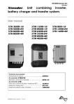


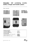


![User Manual BS 15 [ASL]](http://vs1.manualzilla.com/store/data/005675346_1-422b291500c6ff99ebe2f8b515793259-150x150.png)