1
Lab 6
Physics 331 Laboratory Manual
19
LAB 6
Transistor Amplifiers
Reading:
Malvino: Ch.10 through Ch. 12.
Hayes and Horowitz: Class 4, Lab 4 and worked examples, pp. 90ff and 115ff.
In this lab we experiment with different types of transistor amplifiers using the voltagedivider bias.
1.
The Common-emitter Amplifier
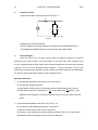
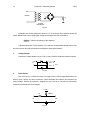
a) Starting from the voltage-divider bias of the last experiment, add an input coupling
capacitor and a bypass capacitor on the emitter resistor to make a common-emitter amplifier.
Calculate the values of the capacitors so that the low-frequency 3 dB point of the ampllifier will be
between 100 and 200 Hz. Measure the amplification using the channel 1 of the scope to display
the input, and the channel 2 for the output. Measure the low-frequency 3dB point. Compare the
measured values with what you expected from calculations. Now investigate the input and output
impedances.
b) You should have noticed the "barn roof" distortion of the design of part (a). Find a
method to reduce the distortion without changing the bias. Measure the effectiveness of your
improvement. How is the amplification affected?
2.
The Emitter-follower Amplifier
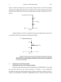
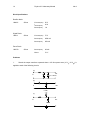
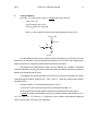
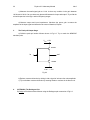
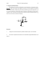
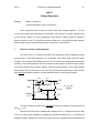
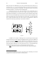
a) Construct the emitter follower circuit shown below in Fig 6.1.
V CC = 12V
130k
1 µF
10 µF
150k
7.5k
Fig 6.1
b) Calculate the base voltage VB, the emitter voltage VE, VCE and the emitter current, IE.
Measure these quantities and compare.