1
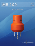
CB400 Us erManual a Dat Buoy About NexSens Technology, Inc. NexSens Technology, Inc. was founded in the late 1990s with a mission to advance the capabilities and simplify the development of environmental monitoring systems. The company specializes in environmental sensors, remote data acquisition and communications technology, easy-to-use computer software, and web-based datacenters. iChart Software is an easy-to-learn, easy-to-use Windows-based software program designed to interface with the industry’s most popular environmental monitoring sensors and systems. A large, multi-vendor instrument library makes setup quick and easy. iChart automates much of the tedious programming, data collection, and manual data processing common with other environmental data collection systems. The SDL500 (Submersible Data Logger) and iSIC (Intelligent Sensor Interface and Control) are state-ofthe-art data loggers that simplify the collection of real-time data from environmental sensors and monitoring instruments. The data loggers support multi-vendor sensor connections and are specifically designed for environmental data monitoring. WQData LIVE is an enterprise class and business critical web-based software solution for environmental data management. It assists with collecting, storing, analyzing, interpreting, sharing and publishing environmental data. The datacenter effectively manages a wide variety of biological, physical, and chemical parameters, along with many other environmental observations and project information. Smart USB-based WQ Sensors include: Temperature, pH, ORP, Dissolved Oxygen, Ammonium, Bromide, Calcium, Chloride, Fluoride, and Nitrate. An integral USB connector on the sensor cable offers a simple, hassle-free connection to a computer without the need for a meter or batteries. T-Node FR temperature systems, based on RS-485 Modbus technology, provide a simple, yet effective, plug-and-play solution for developing multi-sensor networks and temperature strings. The T-Node FR offers pass-through signals for SDI-12 and RS-485, allowing the user to connect Nodes and other environmental measurement sensors along a string. This sensorBUS architecture has been designed so researchers can easily build and customize multi-point temperature strings for more powerful environmental monitoring networks. Coastal Buoys are designed to support offshore monitoring systems. These buoys provide a robust floating platform for coastal water or lake monitoring projects. NexSens products and systems simplify the setup and operation of environmental monitoring networks and help ensure quality data. NexSens Technology, Inc. February 19, 2013 TABLE OF CONTENTS CHAPTER 1 - INTRODUCTION ........................................................................................................................ 3 CHAPTER 2 – COMPONENTS AND SPECIFICATIONS...................................................................................... 4 2.1 CB-400 Components ..................................................................................................................... 4 2.2 CB-400S Components ................................................................................................................... 4 2.3 CB-400/CB-400S Specifications ..................................................................................................... 4 2.4 Common Accessories .................................................................................................................... 5 CHAPTER 3 – GETTING STARTED ................................................................................................................... 6 3.1 System Connections – Power, Communications and Sensors ...................................................... 6 3.2 Gathering Sample Data ................................................................................................................. 7 CHAPTER 4 – BUOY SETUP ............................................................................................................................ 9 4.1 Basic Setup .................................................................................................................................... 9 4.1.1 Running Sensor Cables .......................................................................................................... 9 4.1.2 Installing the SDL500 Submersible Data Logger ................................................................. 10 4.1.3 Securing Buoy Lid ................................................................................................................ 11 4.1.4 Setting Pipe Caps................................................................................................................. 12 4.1.5 Connecting Bottom Sensors ................................................................................................ 12 4.2 Accessories .................................................................................................................................. 13 4.2.1 Deployment Pipe................................................................................................................. 13 4.2.2 Instrument Cage.................................................................................................................. 14 4.2.3 Ballast Weight ..................................................................................................................... 14 CHAPTER 5 – MOORING THE BUOY ............................................................................................................ 16 5.1 Mooring Configurations .............................................................................................................. 16 5.1.1 Single-Point Mooring .......................................................................................................... 16 5.1.2 Two-Point and Three-Point Moorings................................................................................. 17 5.2 Connecting Mooring Hardware .................................................................................................. 17 CHAPTER 6 – SAFELY DEPLOYING THE BUOY .............................................................................................. 19 6.1 Single-Point Mooring Deployment ............................................................................................. 19 6.2 Two-Point and Three-Point Mooring Deployment ..................................................................... 19 CHAPTER 7 – MAINTENANCE ...................................................................................................................... 20 1 7.1 Post-Season Cleaning .................................................................................................................. 20 7.2 Replacing an RBP500 Battery Pack ............................................................................................. 20 CB-400 Data Buoy User’s Manual NexSens Technology, Inc. February 19, 2013 CHAPTER 8 – WARRANTY & SERVICE .......................................................................................................... 23 2 8.1 Limitation of Warranty................................................................................................................ 23 8.2 Corporate Headquarters & Authorized Service Center .............................................................. 23 CB-400 Data Buoy User’s Manual NexSens Technology, Inc. February 19, 2013 CHAPTER 1 - INTRODUCTION NexSens CB-400 data buoy systems are designed for coastal or lake water monitoring applications. The floating platform supports both topside and subsurface environmental monitoring sensors with options for radio, cellular, and satellite data transmission. Temperature strings, multi-parameter sondes, Doppler current meters, weather stations, and other monitoring instruments can all be quickly deployed in protected coastal waters or lakes. The 400 lb. buoyancy buoys are constructed of an inner core of cross-linked polyethylene foam with a tough polymer skin. Three 4” diameter PVC pipes pass through the buoy hull for quick deployment of subsurface instruments. On the topside, a removable tower supports weather monitoring stations and beacons. Multiple configurations are available for the CB-400 data buoy. The standard CB-400 package includes the buoy with no power option. This configuration is designed for use with an SDL500 Submersible Data Logger powered with D-cell alkaline batteries. CB-400S configurations are fitted with three 10-Watt solar panels, which are harnessed together and connected to an RBP500 Rechargeable Battery Pack installed inside the buoy hull. The RBP500 contains an 8.5 A-Hr battery to power the SDL500 and sensors. The SDL500 is configured with five sensor ports for connection to industry-standard digital and analog sensor interfaces, including RS-485, RS-232, SDI-12, 1-wire temp string, 0-2.5V, pulse count and more. Each sensor port offers a UW receptacle with a double O-ring seal for a reliable, waterproof connection. NexSens iChart Software is a Windows-based program for interfacing both locally (direct-connect) and remotely (through telemetry) to a single data buoy or network of data buoys. 3 CB-400 Data Buoy User’s Manual NexSens Technology, Inc. February 19, 2013 CHAPTER 2 – COMPONENTS AND SPECIFICATIONS 2.1 CB-400 Components 2.2 CB-400S Components 2.3 Polymer-coated foam hull Polymer-coated foam tower Stainless steel frame (3) 4” PVC instrument deployment pipes (7) 3/4-inch stainless steel eye nuts, three on top and four on bottom Polymer-coated foam hull Polymer-coated foam tower Stainless steel frame (3) 4” PVC instrument deployment pipes (7) 3/4-inch stainless steel eye nuts, three on top and four on bottom (3) 10-watt solar panels (1) RBP500 Rechargeable Battery Pack with 8.5 A-Hr SLA battery (1) Power harness for connection of solar panels to RBP500 (1) UW-1P 1-meter cable for connection of RBP500 to SDL500 data logger CB-400/CB-400S Specifications Dimensions Tower: 23” diameter, 26” height Hull: 36” diameter, 12” height Overall: 57” height (without instrument cage), 81” height (with instrument cage) Weight CB-400: 95 Lbs. (with SDL500, cage and tower) CB-400S: 120 Lbs. (with solar, RBP500, SDL500, cage and tower) Materials Hull: cross-linked polyethylene foam with polyurea coating Tower: cross-linked polyethylene foam with polyurea coating Maximum Buoyancy Mooring Attachments 400 lbs. (7) ¾” stainless steel eye nuts, (3) top-mounted and (4) bottommounted Suitable Environments Freshwater lakes, protected coastal waters, rivers, reservoirs, estuaries Power Options RBP500: 8.5 A-Hr Sealed Lead Acid (SLA) battery SDL500 (not included): (8) D-cell alkaline batteries Charging CB-400S: (3) 10-Watt solar panels with solar regulator 4 CB-400 Data Buoy User’s Manual NexSens Technology, Inc. February 19, 2013 Figure 2-1: Buoy Components & Dimensions 2.4 5 Common Accessories Item Description Details RBP500 Rechargeable battery pack Provides power to an SDL500 in a CB-400S. Optional on CB-400. CAGE Instrument mooring cage For water sensor deployments. 914 Deployment pipe 4” Sch. 80 PVC pipe with threaded adapter. SDL500 Submersible data logger Fully submersible data logger designed for use with NexSens data buoys. Direct connect. SDL500C SDL500R SDL500I 502-A15 DOR35 DOR70 SSPA375-BOW SSPA500-BOW SSPA625-BOW SS187 HGPC500i A-3-RED Submersible data logger Submersible data logger Submersible data logger LED Beacon Anchor Anchor Shackle Shackle Shackle Stainless steel mooring line Chain, ½” Marker buoy, 18” diameter Cellular telemetry. Radio telemetry. Iridium satellite telemetry. Mounts to buoy tower, 15 flashes per minute. Pyramid anchor, 35 lb. Pyramid anchor, 70 lb. 3 Bow shackle, /8” 1 Bow shackle, /2” 5 Bow shackle, /8” Used for buoy and sensor mooring systems. Galvanized steel chain used for buoy moorings. Used for 2-point and 3-point mooring systems. CB-400 Data Buoy User’s Manual NexSens Technology, Inc. February 19, 2013 CHAPTER 3 – GETTING STARTED Before deploying a CB-400 data buoy , it is very important for the user to become familiar with the hardware connections and operation of the system with iChart software. To begin, lay out the buoy, sensors, data logger, and other components that make up the CB-400 system. Follow the steps in the Chapters 3-5 to test and assemble the system. 3.1 System Connections – Power, Communications and Sensors CB-400 data buoys are designed to accommodate the SDL500 Submersible Data Logger for connection of monitoring instruments. On CB-400 systems without solar charging, the SDL500 is powered with Dcell alkaline batteries. A communications antenna may be installed in the SDL500 top bulkhead port for radio, cellular or satellite telemetry systems. Sensor connections are made on the top port and/or the five ports on the bottom bulkhead. All sensors and devices must have a NexSens UW connector factory installed in order to connect to the SDL500. Consult the SDL500 manual for detailed information on the port characteristics to aid in assigning sensors to the appropriate ports. The available ports are shown in Figure 3-1 below. Figure 3-1: SDL500 Bottom (left) and Top (right) Bulkhead Ports CB-400S systems include an RBP500 Rechargeable Battery Pack and a solar charging kit comprised of three 10-watt solar panels and a power harness with solar regulator. Figure 3-2 is a schematic drawing showing how these components are connected together along with the SDL500. The three 10-Watt solar panels are harnessed together and connected to a solar regulator. This assembly is connected to Port D on the RBP500. Pass-through signals are enabled on the bottom bulkhead of the RBP500 by connecting UW-1P cables from the SDL500 to the RBP500 top bulkhead as shown. The CB-400S package includes (1) UW-1P cable that connects from Port P0 on the SDL500 to Port P0 on the RBP500 top bulkhead. This enables sensors to be connected to Port P0 and Port D on the RBP500 bottom bulkhead. 6 CB-400 Data Buoy User’s Manual NexSens Technology, Inc. February 19, 2013 Figure 3-2: CB-400S Power & Communications Schematic Additional ports can be enabled on the RBP500 by connecting additional UW-1P cables. For example, to enable Port P1 on the RBP500, a UW-1P cable must connect the SDL500 Port P1 to the RBP500 top bulkhead Port P1. To enable Port T on the RBP500, a UW-1P cable must connect the SDL500 Port T to the RBP500 top bulkhead Port T. Port A, the Analog sensor port, is not available on the RBP500 because it is used as a vent for the battery. Sensors with analog outputs can only be connected to Port A on the SDL500. 3.2 Gathering Sample Data Prior to buoy setup and deployment, it is essential to test the monitoring system (sensors, data logger and telemetry) on shore. This is the most important part of the setup process because it allows users to familiarize themselves with the system while confirming that everything is operating properly. Connect all sensors, power the system, and gather sets of sample data with iChart software. Refer to the SDL500 and iChart manuals for additional information on setup and testing of the software, data loggers and sensors. Systems may also ship with project-specific startup documentation provided by NexSens Customer Support. 7 CB-400 Data Buoy User’s Manual NexSens Technology, Inc. February 19, 2013 For troubleshooting assistance, the NexSens Knowledge Base contains detailed information on many of the most common issues that may be encountered: http://nexsens.com/knowledgebase/ NexSens tech support specialists may also be contacted for assistance: NexSens Technology, Inc. 2091 Exchange Court Fairborn, OH 45324 937-426-2151 [email protected] 8 CB-400 Data Buoy User’s Manual NexSens Technology, Inc. February 19, 2013 CHAPTER 4 – BUOY SETUP This section contains detailed instructions on the physical setup of a CB-400 buoy system. Directions are included for a complete CB-400S package with solar panels and RBP500 battery pack. For standard CB400 systems without solar charging, the process is the same, but all sensor connections are made directly to the SDL500 data logger. 4.1 Basic Setup The basic setup for a CB-400 buoy system requires installing sensor cables, connecting sensors and the RBP500 to the SDL500 data logger, installing the SDL500 in the buoy tower, securing the buoy lid, and installing protective pipe caps. The following steps walk the user through this process. Warning: The buoy is very heavy. Take care to lift properly and wear necessary lifting gear (e.g., back braces). Always wear gloves when handling the buoy to protect hands as the buoy may have sharp edges or points. Three people are required for safe lifting. 4.1.1 Running Sensor Cables The buoy has three 4” PVC sensor deployment pipes for deployment of water monitoring instruments. Starting at the bottom of a sensor deployment, feed sensor cables up and into the center chamber of the buoy tower. The cables enter the center chamber through a small slot. Be careful to keep the slot in the sensor deployment pipe lined up with the slot of the buoy tower throughout buoy setup. Figure 4-1: Feeding Sensor Cable into Buoy Tower After feeding sensor cables into the center chamber, reach down into the buoy tower. Grab the cables and pull them through the buoy tower opening (top). On a CB-400S package, the chamber will also have a UW-1P cable coming from the top of the RBP500. 9 CB-400 Data Buoy User’s Manual NexSens Technology, Inc. February 19, 2013 Figure 4-2: Sensor Cable and UW-1P Cable 4.1.2 Installing the SDL500 Submersible Data Logger For SDL500 versions with wireless telemetry (radio, cellular or satellite), an antenna must be connected to the top port. No antenna is needed for the direct-connect SDL500. Instead, the port is plugged or used to connect a topside sensor. Important: Double check that there is an O-ring installed on both the antenna plug and at the bottom of the port. The double O-ring seal ensures that connections do not leak. Install the antenna carefully to avoid damaging the pins. Consult the SDL500 manual for additional information on antenna installation. Figure 4-3: Top Port Pins and O-ring and Connecting SDL500 Antenna Unscrew the plugs from ports that will be used on the bottom of the SDL500. Store them with the SDL500 maintenance kit for future use. For CB-400S systems, Port P0 will always be used to connect to the RBP500 with the UW-1P cable. Remove the large orange O-ring at the bottom of the SDL500. Keep with the SDL500 maintenance kit. 10 CB-400 Data Buoy User’s Manual NexSens Technology, Inc. February 19, 2013 Figure 4-4: SDL500 with Port Plugs and Bottom O-ring Removed Connect the UW-1P cable running from Port P0 on the RBP500 to Port P0 on the SDL500. Connect additional sensor cables to the appropriate ports. Refer to the SDL500 manual for additional information on sensor-specific port selections. Again, double check for the O-rings on all UW plugs and ports. Carefully slide the SDL500 into the center chamber of the buoy tower. Extra cable slack may need to be drawn through the sensor deployment pipes as the SDL500 is lowered. Figure 4-5: SDL500 Cable Connections and Installation 4.1.3 Securing Buoy Lid Install the buoy lid to the tower cap using the (3) 3/8”-16 bolts provided with the system. Include a washer and a lock washer between the bolt head and the lid (the washer sits under the lock washer). Tighten the bolts until the lock washers are flattened, then an additional 1/8” turn. Do not over-tighten the bolts to avoid stripping of the threading on the lid and cap. 11 CB-400 Data Buoy User’s Manual NexSens Technology, Inc. February 19, 2013 Figure 4-6: Buoy Lid Installation Optional beacons or weather sensors to be mounted on the buoy lid can be installed once the lid is securely in place. 4.1.4 Setting Pipe Caps PVC caps are included for additional protection of sensor pass-through tubes. Place a cap over each opening and secure with the provided bolts. Figure 4-7: Pipe Cap on a Sensor Pass-through Tube 4.1.5 Connecting Bottom Sensors On a CB-400S configuration, sensors may connect into Port 0 and Port D on the bottom of the RBP500 battery pack. The RBP500 acts as a pass-through, so the signal availability on enabled RBP500 ports is the same as is available on the SDL500. For example, the RS-232 and SDI-12 signals on the SDL500 Port P0 are also available on the RBP500 Port P0 when the UW-1P cable is attached. Port P1 and Port T can be made available by connecting additional UW-1P cables between the battery pack and SDL500 within the buoy. Port A is unavailable on the bottom side of the buoy because it serves as a top-side battery vent. The SDL500 manual contains detailed information on selecting ports for sensor connections. 12 CB-400 Data Buoy User’s Manual NexSens Technology, Inc. February 19, 2013 Double check that each UW plug and port have an O-ring installed. Missing O-rings will result in water intrusion and sensor failure. See Section 4.1.2 for more information. Figure 4-8: Sensor Connected to RBP500 Port P0 4.2 Accessories Deployment pipes, instrument cages and ballast weights can be added to CB-400 buoy systems. Deployment pipes and instrument cages provide options for secure mounting of sensors, and ballast weights can help to balance the buoy and prevent overturning. 4.2.1 Deployment Pipe Deployment pipe extensions are easily fitted to the built-in sensor deployment pipes to provide extra protection for sensitive monitoring equipment. The 914 deployment pipe is a 4” Schedule 80 PVC pipe section that attaches to the sensor deployment pipes with a threaded adapter. The bottom of the 914 pipe is fitted with a stop bolt to keep sensors in place. To attach a 914 deployment pipe, lay the buoy on its side and thread the deployment pipe into one of the three available pass-through sensor tubes. Take caution to avoid cross-threading of the adapter. Also make sure the built-in deployment pipes do not rotate inside the buoy hull. The slotted top end must be properly aligned with the slot in the buoy tower to allow sensor cables to run from the tower to the deployment pipe assembly. Figure 4-9: CB-400S with 914 Deployment Pipe 13 CB-400 Data Buoy User’s Manual NexSens Technology, Inc. February 19, 2013 4.2.2 Instrument Cage The CB-400 buoy allows an instrument cage to be installed on the bottom. Sensors can be securely attached to the instrument cage. To install the cage, first remove the 1-3/4”-10 x 4” bolt, 1-3/4” lock washer and 1-3/4”-10 nut from the buoy frame. Figure 4-10: Bolt on Buoy Frame Run the bolt downward through the buoy frame and top of the cage. Place the lock washer and nut onto the bolt. Figure 4-11: Securing the Cage Assembly Tighten securely with large crescent wrenches, and weld the connection to prevent the cage from coming loose in rough water. 4.2.3 Ballast Weight Proper ballast weight is essential to prevent buoy overturning. Carefully consider the site-specific ballast requirements prior to deployment. 14 CB-400 Data Buoy User’s Manual NexSens Technology, Inc. February 19, 2013 A 25 lb. ballast weight is available for installation to the bottom of the instrument cage for additional balance. Begin installation by inserting the 9-3/4” threaded rod section through the ballast weight and bottom of the buoy frame or instrument cage assembly. Figure 4-12: Inserting the Threaded Rod On the bottom end of the rod, tighten a 1-3/4” eye nut with a 1-3/4” lock washer. Tighten the top end of the rod securely to the buoy frame or instrument cage with a 1-3/4”-10 nut and 1-3/4” lock washer. Weld the connections to prevent loosening in rough water. Figure 4-13: Securing the Ballast Weight 15 CB-400 Data Buoy User’s Manual NexSens Technology, Inc. February 19, 2013 CHAPTER 5 – MOORING THE BUOY This section contains only general information on the available mooring options. To develop an effective mooring strategy, a variety of application-specific criteria must be thoroughly reviewed prior to deployment. Adverse weather conditions, water level fluctuations, currents and wave action, debris loads, and other factors can cause entanglement of mooring lines, submersion of the buoy, and damage to sensors and other components. NexSens does not endorse any particular mooring strategy for any application unless the end user performs a thorough review of the site conditions with the NexSens engineering team. 5.1 Mooring Configurations CB-400 buoys contain a total of four bottom-side eye nuts to accommodate single-point, two-point and three-point mooring styles. Three of the eye nuts are arranged in a semi-circle directly at the bottom of the hull for two- and three-point moorings. The final eye nut is located on the bottom of the buoy frame or instrument cage if one is installed. This nut is used for single-point moorings or to deploy sensor chains. 5.1.1 Single-Point Mooring Single-point moorings are used in extremely calm waters when monitoring sensors are attached to the instrument cage or housed in deployment pipes. The sensors are thus protected and less vulnerable to damage caused by subsurface debris, high currents, and entanglement from anchor lines. In a single-point configuration, a stainless steel mooring line connects the buoy directly to a bottom chain and anchor. The anchor, bottom chain, and mooring line are assembled and attached to the buoy prior to deploying the system. Figure 5-1: Typical Single-Point Mooring Setup 16 CB-400 Data Buoy User’s Manual NexSens Technology, Inc. February 19, 2013 5.1.2 Two-Point and Three-Point Moorings Two-point moorings are commonly used when monitoring sensors are deployed in the water column below the buoy. In this setup, the mooring lines are pulled taut away from the buoy, freeing the water column for a suspended sensor line. In most two-point configurations, mooring lines connect the data buoy to small marine marker buoys. These marker buoys are shackled to another mooring line that runs to the seafloor and connects via a bottom chain to an anchor. Three-point configurations are similar to two-point, but a third set of anchors, mooring lines and marker buoys keep the buoy in place. Figure 5-2: Typical Two-Point Mooring Setup 5.2 Connecting Mooring Hardware Stainless steel bow shackles are used to connect the various mooring components (mooring lines, marker buoys, chains and anchors) together and to the CB-400 buoy. Bow shackles must be properly connected and secured to prevent hardware from loosening and becoming detached over time in rough water conditions. After hand-tightening a bow shackle, use a crescent wrench to tighten the connection. Then, run a cable tie through the hole on the shackle pin and run this through the loop of the shackle. Pull tightly to secure. 17 CB-400 Data Buoy User’s Manual NexSens Technology, Inc. February 19, 2013 Figure 5-3: Attaching Mooring Lines Figure 5-4: Cable Tie Installed on Bow Shackle A 1/2” bow shackle is used to connect mooring lines to the CB-400 buoy eye nuts and to 1/2” bottom chains. Larger, 5/8” bow shackles are required for connection of marker buoys and anchors. Figure 5-5: Mooring Components 18 CB-400 Data Buoy User’s Manual NexSens Technology, Inc. February 19, 2013 CHAPTER 6 – SAFELY DEPLOYING THE BUOY Personnel safety should be the number one priority when deploying a buoy. It is essential to use the proper equipment (work boat, lifting rig, etc.) to deploy any buoy system. Buoy systems are heavy and personnel can quickly become entangled with mooring lines and anchors. Safety and flotation gear should be worn at all times when working on or near the water. Remember to perform a complete system test on shore before deployment. Communication and sensor issues are much easier to troubleshoot before the system is in the water. See Chapter 3 for additional information. 6.1 Single-Point Mooring Deployment Deployment of a single-point mooring system is a fairly straightforward process. With the buoy in the boat, begin by connecting all mooring hardware (see Section 5.2) including the connection of the mooring line to the bottom eye nut of the CB-400. Next, with the buoy still in the boat, lift the anchor over the side of the boat and drop in the water at the chosen deployment location. Be sure that the mooring line and bottom chain assembly is long enough that dropping the anchor does not pull the buoy over the side of the boat. Finalize any sensor connections and apply power, then lift the buoy over the side of the boat and set in the water. Deployment of the system is complete. 6.2 Two-Point and Three-Point Mooring Deployment For deployment of a two- or three-point mooring system, first connect all mooring components inside the boat. Navigate to the chosen location for the first anchor. Lift the anchor and marker buoy over the side of the boat and drop into the water. Be sure that the mooring line and bottom chain assembly is long enough that dropping the anchor does not pull the buoy over the side of the boat. Then, move to the location where the buoy will sit. The distance from the position of the first anchor to the buoy location is determined by the lengths of the mooring lines that are attached. Pay out the mooring line from the marker buoy to the CB-400 as the boat is moved. Finalize sensor connections and apply power, then lift the buoy over the side of the boat and set in the water. Move onward to the location of the second anchor. Lift the anchor and marker buoy over the side of the boat and drop into the water. Repeat this process if a third mooring point is to be used. 19 CB-400 Data Buoy User’s Manual NexSens Technology, Inc. February 19, 2013 CHAPTER 7 – MAINTENANCE System maintenance requires that the buoy is regularly visited for inspection and sensor calibrations. If solar panels are present, clean thoroughly as needed to optimize performance. Solar panels are made of glass and will break. Avoid dropping tools or impacting them with other objects. 7.1 Post-Season Cleaning To decommission the buoy, first pull the sensor mooring line followed by anchor and buoy lines. Scrub all components to remove biological fouling and store buoy in a clean, dry location. A pressure washer may be used to remove fouling on the buoy hardware, but take caution before using a pressure washer on sensors and other sensitive equipment. If possible, store the buoy near a window facing south to prevent excessive draining that can be harmful to the rechargeable battery. Alternatively, bring the buoy outside on sunny days to periodically charge the battery. 7.2 Replacing an RBP500 Battery Pack CB-400S configurations ship with the RBP500 Rechargeable Battery Pack preinstalled in the buoy hull. The RBP500 includes an internal 8.5 A-Hr sealed lead acid (SLA) battery that is recharged by the 10-Watt solar panel assemblies. The typical lifespan of the SLA battery is 1-3 years. The battery should be replaced as needed or a minimum of every 3 years. Removal of the buoy tower is necessary in order to access the RBP500 for removal and replacement. To gain access to the hull, the SDL500 must first be removed from the tower. Remove the 3/8”-16 bolts from the buoy top lid and store in a safe location. Carefully pull the SDL500 through the top of the buoy to expose the sensor connections on the bottom bulkhead. Disconnect the UW-1P cable from port P0 and any other sensors connected. Set the SDL500 aside with the buoy top lid. Next, the topside stainless steel eye nuts must be removed. Use a large wrench to loosen the eye nuts. Remove the eye nuts, lock washers and washers and store them in a safe location. Figure 7-1: Loosen Topside Eye Nuts 20 CB-400 Data Buoy User’s Manual NexSens Technology, Inc. February 19, 2013 Remove the lid and store with the eye nuts. Gently lift the tower upward from the hull. Prop the tower about 12” above the hull, or have an assistant hold the tower in this position. Remove the solar panel power cable from port D on the top RBP500 bulkhead. After disconnecting this cable, continue lifting the tower until it is free from the buoy. Set this aside with the SDL500 and other hardware. Be careful to avoid damaging the PVC guide pipes that protrude from the bottom of the tower. Figure 7-2: Disconnecting Power Cable from Port D and Removing the Tower Lift the RBP500 up from the buoy hull to remove. Make sure the replacement RBP500 has an orange Oring installed around the top to hold it in place. Lower the replacement RBP500 into the hull chamber. Figure 7-3: Replacing the RBP500 Reconnect the UW-1P cable that connects the RBP500 to the SDL500 to Port 0 on the top bulkhead of the battery pack. Carefully slide the tower back onto the hull. Feed the UW-1P cable that connects the RBP500 to the SDL500 through the center of the tower so that it can be reconnected to the SDL500. Before lowering the tower completely, reconnect the solar panel power cable to Port D of the RBP500. Important: Double check for O-rings on the UW connectors and inside the RBP500 and SDL500 ports. 21 CB-400 Data Buoy User’s Manual NexSens Technology, Inc. February 19, 2013 Figure 7-4: Reconnecting Power Cable to Port D Reconnect the UW-1P cable and any sensors to the SDL500. Reinstall the SDL500 inside the buoy tower. Tighten the eye nuts using a large wrench and reinstall the buoy lid. For eye nut reinstallation, set a washer and lock washer onto the lid at each location. Tighten the eye nuts by hand or with a large wrench as needed to flatten the lock washers. Figure 7-5: Tightening Eye Nuts 22 CB-400 Data Buoy User’s Manual NexSens Technology, Inc. February 19, 2013 CHAPTER 8 – WARRANTY & SERVICE NexSens Technology, Inc. warrants products against defects in materials or workmanship for a period of 12 months from the date of delivery to the original customer. This warranty is limited to the replacement or repair of such defects, without charge, when the product is returned to NexSens Technology, Inc. Damage due to accidents, misuse, tampering, lack of reasonable care, loss of parts, failure to perform prescribed maintenance, or accidents of nature are not covered. This warranty excludes all other warranties, express or implied, and is limited to a value not exceeding the purchase price of the instrument. 8.1 Limitation of Warranty This warranty is not applicable to any NexSens Technology, Inc. product damage or failure caused by failure to install, operate or use the product in accordance with NexSens Technology, Inc. written instructions; abuse or misuse of the product; failure to maintain the product in accordance with NexSens Technology, Inc. written instructions; any improper customer repairs to the product; use by the customer of defective or improper components or parts in servicing or repairing the product; or customer modification of the product in any way not expressly authorized by NexSens Technology, Inc. NexSens Technology, Inc. products are not authorized for use as critical components in any life support system where failure of the product may affect its safety or effectiveness. 8.2 Corporate Headquarters & Authorized Service Center NexSens Technology, Inc. 2091 Exchange Court Fairborn, OH 45324 Phone: 937.426.2703 | Fax: 937.426.1125 Email: [email protected] 23 CB-400 Data Buoy User’s Manual