1
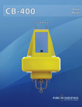
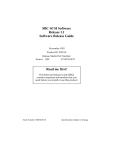
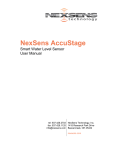
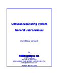
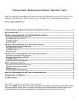
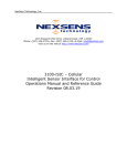
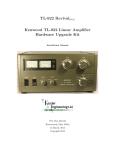
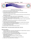
Title Page
About NexSens
NexSens Technology, Inc. was founded in the late 1990s with a mission to
advance the capabilities and simplify the development of environmental
monitoring systems. The company specializes in environmental sensors,
remote data acquisition and communications technology, easy-to-use
computer software, and web based datacenters.
iChart Software is an easy-to-learn, easy-to-use Windows-based software
program designed to interface with the industry’s most popular
environmental monitoring sensors and systems. A large multi-vendor
instrument library makes setup quick and easy. iChart automates much of
the tedious programming, data collection, and manual data processing
common with other environmental data collection systems.
The SDL500 (Submersible Data Logger) and iSIC (Intelligent Sensor
Interface and Control) are state-of-the-art data loggers that simplify the
collection of real-time data from environmental sensors and monitoring
instruments. The data loggers support multi-vendor sensor connections
and are specifically designed for environmental data monitoring.
WQData PRO is an enterprise class and business critical web-based
software solution for environmental data management. It assists with
collecting, storing, analyzing, interpreting, sharing, and publishing
environmental data. The datacenter effectively manages a wide variety of
biological, physical, and chemical parameters, along with many other
environmental observations and project information.
WQSensors smart USB-based sensors include: Temperature, pH, ORP,
Dissolved Oxygen, Ammonium, Bromide, Calcium, Chloride, Fluoride, and
Nitrate. An integral USB connector on the sensor cable offers a simple,
hassle-free connection to a computer without the need for a meter or
batteries.
T-Node temperature systems, based on sensorBUS technology, provide a
simple, yet effective, plug-and-play solution for developing multi-sensor
networks and temperature strings. sensorBUS was developed to replace,
expand, and enhance centralized parallel wiring for prevailing analog and
digital signal transmissions. With integral 1-wire, SDI-12 and RS-485
interfaces, sensorBUS provides versatile sensor networking capability.
Monitoring Buoys are designed to support offshore monitoring systems.
These buoys provide a robust floating platform for inland water monitoring
projects.
NexSens products and systems simplify the setup and operation of
environmental monitoring networks and help ensure quality data.
Table of Contents
Overview ................................................. 1
What’s Included ..................................... 2
Common Accessories .............................................. 2
Specifications......................................... 3
Getting Started ....................................... 3
Pre-deployment Test ............................. 4
Power the Data Logger ............................................ 4
Install the Data Logger ............................................. 5
Connect Sensors ..................................................... 6
Confirm Data Collection & Transmission .................. 7
Prepare for Deployment ........................ 8
Setup the Sensor Mooring ....................................... 8
Assemble Anchor Line ............................................. 8
Safely Deploy the Buoy ......................... 9
Surface Deployments............................................... 9
Sub-Surface Deployments ..................................... 10
Satellite Buoy ........................................................................................ 10
Standalone Buoy ................................................................................... 10
Material Safety Data Sheets ................ 12
Warranty and Service .......................... 12
OVERVIEW
Overview
The MB-100 is designed for years of service in both surface
and sub-surface applications. The data buoy's construction
includes an inner core of cross-linked polyethylene foam,
heavy polymer skin, and stainless steel frame. All sensor
connections are made below the surface with waterproof
connectors. A wireless transmitter can be positioned above
the water but hidden and protected under the buoy hood.
The MB-100 data buoy is designed to accommodate NexSens
SDL500 submersible data loggers. A fully loaded system
(with data logger and batteries) weighs just over 30 lbs. and
is easily deployed by one person from any vessel. Simply
attach a single-point mooring assembly and throw it
overboard. The buoy will right itself and begin logging data
immediately. If equipped with an optional communication
package, it will start transmitting data via radio-to-shore,
cellular, or Iridium satellite telemetry.
Figure 1: MB-100 Data buoy
1
WHAT’S INCLUDED
What’s Included
The MB-100 data buoy includes a foam hull with stainless
steel frame and a single mooring eye, protective foam hood,
and three threaded nuts used to securing the hood.
Common Accessories
Table 1: Accessories commonly used with MB-100 data buoys
Part Number Description
Details
SDL500
Submersible data
logger
Fully submersible
data logger designed
for use with NexSens
data buoys.
Telemetry options
include cellular,
radio, and satellite.
DOR35
Anchor
Pyramid anchor, 35
lb.
DOR70
Anchor
Pyramid anchor, 70
lb.
SSPA375-BOW
Shackle
Bow shackle, 3/8”
SSPA500-BOW
Shackle
Bow shackle, 1/2”
SSPA625-BOW
Shackle
Bow shackle, 5/8”
SS187
Stainless steel
mooring line
Used for buoy and
sensor mooring
systems.
HGPC500i
Chain, ½”
Galvanized steel
chain used for buoy
moorings.
2
SPECIFICATIONS
Specifications
Table 2: NexSens MB-100 data buoy specifications
Dimensions
Hull: 18” diameter, 16” height
Overall: 34” height
24 lbs (no payload)
Weight
Materials
38 lbs (with SDL500 and
batteries)
Hull, Hood: cross linked
polyethylene foam with polymer
skin
Frame: 304 stainless steel
Surface Buoyancy
100 lbs
Subsurface Buoyancy
60 lbs
Minimum Deployment
Depth
12”
Mooring Attachment
¾” stainless steel eye nut
Suitable Environments
Freshwater, brackish and
saltwater including lakes, rivers,
streams, reservoirs and coastal
waters.
Mooring
Single point
Power
(8) internal D-cell alkaline
batteries are used to power
SDL500 data logger
Getting Started
The NexSens MB-100 data buoy ships fully assembled.
Common accessories such as the SDL500 data logger and
single point mooring hardware may require some user
assembly.
The buoy hood must be removed to get started. To do this,
loosen and remove the three threaded nuts that secure the
hood to the frame. Use 3/16” handled Allen wrench provided
with the SDL maintenance kit for additional leverage if
necessary.
3
PRE-DEPLOYMENT TEST
Figure 2: Removing a threaded nut from the MB-100 to allow for hood
removal
After removing the threaded nuts, simply lift the hood off of
the hull to gain access to the central buoy well. This is where
the SDL500 data logger will be installed.
Pre-deployment Test
Prior to deployment, it is essential to test the monitoring
system (sensors, data logger, and telemetry) on shore. This
will allow users to familiarize themselves with the system
and confirm proper operation.
Power the Data Logger
NOTE
The SDL500 is
equipped with reverse
polarity protection. No
damage will occur if the
batteries are inserted
incorrectly.
Unthread the battery lid from the SDL500 communication
bulkhead. Insert eight D-Cell alkaline batteries into the data
logger. Note the correct polarity shown on the labels just
inside the battery tubes. See the appropriate SDL500 manual
for additional information.
4
PRE-DEPLOYMENT TEST
Figure 3: Installing batteries in the SDL500
Install the Data Logger
Remove the orange rubber o-ring from the bottom (gray)
end of the data logger.
Figure 4: SDL500 with bottom orange o-ring removed
5
PRE-DEPLOYMENT TEST
Insert the SDL500 into the central well of the data buoy so
that the white battery lid is on the topside of the buoy.
Figure 5: SDL500C cellular data logger with antenna shown inserted into MB100 central buoy well
Connect Sensors
To facilitate sensor connections the bottom guard should be
removed using the 3/16” handled Allen wrench supplied in
the SDL maintenance kit.
Figure 6: Removing bottom guard from SDL500 data logger using wrench
from SDL maintenance kit
6
PRE-DEPLOYMENT TEST
Connect sensors to the SDL500 sensor bulkhead. Refer to
the appropriate SDL user manual and sensor interface
manuals for additional information including port
recommendations.
NOTE
Be sure to route the
sensor cables through
the guard prior to
connecting to the SDL
sensor bulkhead.
Figure 7: SDL500 with bottom guard removed and sensors connected
Reconnect the guard to the SDL500 data logger.
Confirm Data Collection & Transmission
Launch iChart software and confirm that the SDL500 and
sensors are communicating properly. Refer to the
appropriate data logger manual and iChart software manual
for additional information as required.
The pre-deployment check is complete. The buoy, data
logger, and sensors can now be prepared for deployment.
7
PREPARE FOR DEPLOYMENT
Prepare for Deployment
Since the MB-100 data buoy supports 1-point moorings, the
sensor mooring line also functions as the single point anchor
line used for buoy mooring.
Setup the Sensor Mooring
NOTE
Sensor mooring line
should be shorter than
the approximate depth
of the water column.
Bottom chain allows for
fluctuations in water
level for surface buoy
applications.
Lay the SDL500 data logger (pre-installed in the MB-100
data buoy) out on a flat surface. Secure the connected
sensors to the sensor mooring line using sensor clamps and
plastic cable ties.
Figure 8: Sensor mooring line with T-Node temperature sensors and YSI
water quality sonde
Connect the sensor mooring line to the mooring eye on the
MB-100 data buoy using a 1/2” bow shackle.
Assemble Anchor Line
Connect the anchor and bottom chain with a 5/8” shackle,
and then attach the assembly to the sensor mooring line
using a 1/2” shackle (see Figure 9).
8
SAFELY DEPLOY THE BUOY
Figure 9: Typical sensor mooring and anchor line used with MB-100 data
buoys
Safely Deploy the Buoy
WARNING
Proper safety and
flotation gear should be
worn at all times when
working on or near the
water.
Personnel safety should be the number one priority when
deploying the buoy. Follow these steps closely to ensure safe
deployment.
Prior to deployment, make sure that the MB-100 data buoy,
SDL500 data logger with batteries, and the sensor mooring
and anchor line are securely attached in a single assembly.
This is will help ensure a quick and easy deployment.
Surface Deployments
Water quality data is typically referenced by distance from
the water’s surface. In such applications bottom mooring
chain permits flucutations in water level, which effectively
9
SAFELY DEPLOY THE BUOY
WARNING
The buoy mooring
systems are heavy and
personnel can quickly
become entangled with
mooring lines and
anchors.
allows the buoy to drift along the water’s surface in the
vicinity of the mooring system.
To deploy a surface buoy, simply boat to the desired
monitoring location and place the MB-100 buoy with data
logger in the water. Allow the buoy to right itself, paying out
the sensor mooring and anchor line as necessary. Make sure
the anchor is still on board the boat.
With the data buoy floating in location, move the boat while
paying out most of the sensor mooring and anchor line and
bottom chain. Drop the anchor.
The data buoy is now deployed and operational.
Sub-Surface Deployments
Sub-surface deployments are used for bottom referencing
water quality data. Data is bottom referenced when it is
collected by sensors that are fixed along a mooring line in a
water column that is not free to move vertically. As a result,
water quality data is always collected at a fixed distance
from the water body’s floor (see Figure 10).
Sub-surface deployments are completed in the same way as
surface water deployments. However, prior to a sub-surface
deployment, it is highly recommended that the MB-100
foam hood be removed. This will lighten the buoyancy of
the buoy, providing a setup that is more stable with less
anchor weight.
Satellite Buoy
Sub-surface MB-100 deployments are most effective when
used along with a larger surface buoy. In these
configurations, the submersed SDL500 data logger acts as a
“satellite buoy” and transmits the sensor data it collects to
another SDL data logger on the surface via direct cabling.
The surface data logger is typically outfitted with a remote
telemetry option for automatic data upload capability.
Standalone Buoy
Alternatively, MB-100 data buoys can be deployed as
standalone systems sub-surface. For such applications,
however, the entire system including the mooring and
10
SAFELY DEPLOY THE BUOY
anchor must be pulled each time batteries need changed or
sensors require maintenance or calibration.
Figure 10: MB-100 pictured in a surface buoy deployment (left) and a
standalone sub-surface deployment (right), both deployments include YSI
water quality sondes and T-Node temperature strings
11
MATERIAL SAFETY DATA SHEETS
Material Safety Data Sheets
Material Safety Data Sheets can be found at:
http://www.nexsens.com/support/msds.htm
Warranty and Service
WARNING
NexSens Technology,
Inc. products are not
authorized for use as
critical components in
any life support system
where failure of the
product may affect its
safety or effectiveness.
NexSens Technology, Inc. warrants products against defects
in materials or workmanship for a period of 12 months from
the date of delivery to the original customer. This warranty is
limited to the replacement or repair of such defects, without
charge, when the product is returned to NexSens
Technology, Inc. Damage due to accidents, misuse,
tampering, lack of reasonable care, loss of parts, failure to
perform prescribed maintenance, or accidents of nature are
not covered. This warranty excludes all other warranties,
express or implied, and is limited to a value not exceeding
the purchase price of the instrument.
Limitation of Warranty
This warranty is not applicable to any NexSens Technology,
Inc. product damage or failure caused by (i) failure to install,
operate or use the product in accordance with NexSens
Technology, Inc. written instructions, (ii) abuse or misuse of
the product, (iii) failure to maintain the product in
accordance with NexSens Technology, Inc. written
instructions, (iv) any improper repairs to the product, (v) use
by you of defective or improper components or parts in
servicing or repairing the product, or (vi) modification of the
product in any way not expressly authorized by NexSens
Technology, Inc.
Corporate Headquarters and Authorized Service Center
NexSens Technology, Inc.
1415 Research Park Drive
Beavercreek, Ohio 45432
Phone 937.426.2703 ● Fax 937.426.1125
E-Mail [email protected]
Revision: 01
Revision Date: December 2, 2010
12
WARRANTY AND SERVICE
13