1
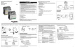
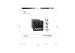
ENGLISH
Instruction Bulletin
POWERLOGIC® Ethernet Gateway EGX100
63230-319-204A1
2/2006
User’s Guide
Instrucciones en Español: página 19
Instructions en Français: page 39
Anweisungen auf Deutsch: Seite 59
Retain for future use.
TABLE OF CONTENTS
INTRODUCTION ........................................................................................ 2
Supported Ethernet Protocols..................................................................... 2
Hardware .................................................................................................... 2
Additional Resources .................................................................................. 3
ACCESSING THE EGX OVER A NETWORK ........................................... 3
Logging into the EGX.................................................................................. 3
Logging Out ................................................................................................ 3
EGX USER INTERFACE OVERVIEW ....................................................... 4
SETUP ........................................................................................................ 5
Ethernet and TCP/IP Settings..................................................................... 5
Duplicate IP Address Detection............................................................. 6
Serial Port ................................................................................................... 7
Device List .................................................................................................. 8
Master Mode Device List Setup ............................................................ 8
Slave Mode Device List Setup .............................................................. 9
User Accounts........................................................................................... 10
Web Page Access..................................................................................... 11
Modbus TCP/IP Filtering........................................................................... 12
SNMP Parameters .................................................................................... 13
DIAGNOSTICS ......................................................................................... 14
Statistics.................................................................................................... 14
Interpreting Statistics........................................................................... 15
Read Device Registers ............................................................................. 17
FIRMWARE .............................................................................................. 18
Finding the Firmware Version ................................................................... 18
Getting New Firmware .............................................................................. 18
Updating the Firmware File....................................................................... 18
1
POWERLOGIC® Ethernet Gateway
Introduction
INTRODUCTION
63230-319-204A1
2/2006
ENGLISH
This manual is to be used with a POWERLOGIC® EGX100 with firmware
version 2.0 or higher. For installation information, see the installation
manual.
The EGX100 is a communications device that provides connectivity
between Ethernet (Modbus TCP/IP) and serial line devices, allowing
Modbus TCP/IP clients to access information from serial slave devices. It
also allows serial master devices to access information from serial slave
devices distributed across an Ethernet network.
Supported Ethernet Protocols
The EGX supports the following Ethernet protocols:
•
Modbus TCP/IP: Modbus TCP/IP is a combination of the Modbus
protocol, which provides master-slave communication between devices,
and TCP/IP, which provides communications over an Ethernet
connection. Modbus TCP/IP is used to exchange data between the EGX
and other compatible Modbus TCP/IP devices via TCP port 502.
•
Hypertext Transfer Protocol (HTTP): HTTP is a network protocol that
handles the delivery of files and data on the World Wide Web. It
provides web server functionality via TCP port 80. Remote configuration
of the EGX and the viewing of diagnostic data is possible using a web
browser.
•
File Transfer Protocol (FTP): FTP is a network protocol that provides
the ability to transfer files over the Internet from one computer to
another. FTP is used to transfer firmware updates to the EGX via TCP
port 21.
•
Simple Network Management Protocol (SNMP): Based on MIB2
format, SNMP provides the ability to store and send identifying and
diagnostic information used for network management purposes via UDP
port 161 .
•
Address Resolution Protocol (ARP): ARP is used to convert IP
addresses to Ethernet addresses. ARP requests are sent by the EGX to
determine if its address is a duplicate IP address (see “Duplicate IP
Address Detection” on page 6).
Hardware
RJ45 Ethernet port
Control power
LEDs for Ethernet
and serial
communications
Power and
Status LED
RS485 serial port
Bias, termination,
and 2-wire/4-wire
jumper switches
Reset
button
RS232 serial port
(RJ45 connector)
2
© 2006 Schneider Electric. All Rights Reserved.
Additional Resources
Documentation: Go to www.powerlogic.com, select your country >
literature > Communication Devices > Ethernet EGX > Instructional, and
then click the manual you want to download.
Firmware: Go to www.powerlogic.com, select your country > downloads >
ECC/EGX Firmware, and then click the firmware file you want to download.
NOTE: If you do not have a user name and password, follow the instructions
on the web site.
ACCESSING THE EGX OVER A
NETWORK
After you set up the Ethernet parameters (see the installation guide), you
can access the EGX over an Ethernet LAN using Internet Explorer 6.0 or
higher.
Logging into the EGX
Action
Result
1. Launch Internet Explorer 6.0 or higher.
Opens Internet Explorer.
2. In the Address text box, type the address
of your EGX (169.254.0.10 is the default),
then press Enter.
Opens the Login dialog box.
3. Type your user name (Administrator is the
default) and password (Gateway is the
default) into the text boxes, then click OK.
Enters the user name and password, then
opens the EGX home page.
4. Click Setup to access the EGX setup page, Opens the Setup or Diagnostics pages.
or click Diagnostics to access the EGX
diagnostics page.
Figure 1:
The EGX Home Page
Menu bar
Logging Out
We recommend logging out whenever you do not need access to the EGX.
To log out of the EGX configuration session, click Log Out to end your
session.
© 2006 Schneider Electric. All Rights Reserved.
3
ENGLISH
POWERLOGIC® Ethernet Gateway
Accessing the EGX Over a Network
63230-319-204A1
2/2006
POWERLOGIC® Ethernet Gateway
EGX User Interface OVERVIEW
ENGLISH
EGX USER INTERFACE
OVERVIEW
63230-319-204A1
2/2006
The EGX ships with seven pre-installed web pages used for EGX setup and
configuration. See Table 1 for a description of each web page.
Table 1:
EGX static web pages
EGX Web Page
Description
See
Page
Setup
Ethernet & TCP/IP
Configure Ethernet and TCP/IP communication settings.
5
Serial Port
Set up or change serial communication parameters.
7
Device List
Identify serial devices on the daisy chain.
8
User Accounts➀
Create and edit groups and users.
10
Web Page Access➀
Select web page access rights for each user group.
11
Modbus TCP/IP Filtering➀
Set up which IP addresses can access the EGX through
Modbus TCP/IP.
12
SNMP Parameters➀
Enable and configure the Simple Network Management
Protocol (SNMP), which allows the EGX to identify itself
to network devices requesting SNMP data.
13
Statistics
Displays diagnostic data used to troubleshoot network
problems. This page also contains information about
your specific EGX, including the serial number,
manufacturing date, and Media Access Control (MAC)
address.
14
Read Device Registers
Allows EGX administrators to read register data from a
serial device connected to the EGX.
17
Diagnostics
➀Accessible
4
by administrator only
© 2006 Schneider Electric. All Rights Reserved.
POWERLOGIC® Ethernet Gateway
Setup
63230-319-204A1
2/2006
To access the Setup web page links, click Setup on the EGX menu bar.
ENGLISH
SETUP
Ethernet and TCP/IP Settings
Action
Result
1. From the Setup page, click Ethernet &
TCP/IP.
Opens the Ethernet & TCP/IP page.
2. Select your frame format and media type.
Contact your network administrator if you
do not know.
Selects the frame format and media type.
3. Enter your IP address, subnet mask, and
default gateway address assigned to your
EGX by your network administrator.
Enters the Ethernet parameters for the EGX.
4. Click Apply.
Updates the EGX Ethernet and TCP/IP
settings.
NOTE: If you enter an IP address that is used
by another device, you will be prompted to
select a new IP address. See “Duplicate IP
Address Detection” on page 6.
* See Table 2 on page 5 for a list of options.
NOTE: After making changes to the Ethernet parameters and clicking
Apply, the EGX will reboot.
Figure 2:
Table 2:
Ethernet & TCP/IP Page
EGX Ethernet and TCP/IP Settings
Option
Description
Setting
Frame Format
Used to select the format for data sent over Ethernet II, 802.3 SNAP
an Ethernet connection.
Default: Ethernet II
Media Type
Used to define the physical Ethernet
connection or media type.
IP Address
Used to enter the static IP address of the
EGX.
0.0.0.0 to 255.255.255.255
Subnet Mask
Used to enter the Ethernet IP subnet mask
address of your network.
0.0.0.0 to 255.255.255.255
Default Gateway
Used to enter the gateway (router) IP
0.0.0.0 to 255.255.255.255
address used for wide area network (WAN)
Default: 0.0.0.0
communications.
•
•
•
•
•
10T/100Tx Auto
10BaseT-HD
10BaseT-FD
100BaseTX-HD
100BaseTX-FD
Default: 10T/100Tx Auto
© 2006 Schneider Electric. All Rights Reserved.
Default: 169.254.0.10
Default: 255.255.0.0
5
POWERLOGIC® Ethernet Gateway
Setup
Duplicate IP Address Detection
63230-319-204A1
2/2006
ENGLISH
While connected to your network, the EGX publishes its IP address. To
avoid any duplicate IP address conflicts, the EGX uses the Address
Resolution Protocol (ARP) to see if any other device on your network is
using the same IP address. Table 3 below explains how the EGX handles a
duplicate IP address when it is detected.
Table 3:
Duplicate IP Detection Scenarios
Scenario
Duplicate IP Detected
Boot Process /
Power Restore
Reverts to the default EGX IP
Four blinks, pause pattern
address, subnet mask, and gateway
address. ARP requests are sent every
15 seconds until the IP address is
available. When the IP address
becomes available, the EGX will use
it.
Ethernet Link Detected
Power/Status LED
Manual Address Change EGX keeps it’s previous IP address
and displays a message indicating
that the IP address is already in use
by another device.
Receives an ARP request Reverts to the default EGX IP
address, subnet mask, and gateway
address if a connected device sends
four ARP requests for the EGX’s IP
address. The EGX will send ARP
requests every 15 seconds until the
IP address is available again. When
the IP address becomes available,
the EGX will use it.
6
Four blinks, pause pattern
© 2006 Schneider Electric. All Rights Reserved.
POWERLOGIC® Ethernet Gateway
Setup
63230-319-204A1
2/2006
Serial Port
Result
ENGLISH
Action
1. From the Setup page, click Serial Port.
Opens the Serial Port page.
2. Select your mode, physical interface,
transmission mode, baud rate, parity, and
response timeout (see Table 4 on page 7).
Selects the serial port options.
3. If you select Slave mode, enter the IP
addresses for the remotely connected
devices (see Table 4 on page 7).
Enters the IP addresses of the remote devices.
4. Click Apply.
Updates the EGX Serial Port settings.
Figure 3:
Serial Port Page
Table 4:
Serial Port Settings
Option
Mode
Description
Used to select how the COM port on the
EGX is utilized (master or slave).
Setting
Master, Slave
Default: Master
NOTE: When the Mode is changed, the
EGX reboots.
Physical Interface
Used to select how the EGX serial port is
physically wired.
RS485 4-wire, RS485 2-wire,
or RS232
Transmission
Mode
Used to select how data is transmitted over Master mode: Automatic,
a serial connection.
Modbus ASCII
Default: RS485 2-wire
Slave mode: Modbus RTU,
Modbus ASCII
Default:
•
•
Master mode: Automatic
Slave mode: Modbus RTU
NOTE: Automatic mode allows
you to communicate to
Modbus RTU, Jbus, and
POWERLOGIC(SY/MAX)
slave devices on the same
daisy chain.
Baud Rate
Used to select the data transmission speed 2400, 4800, 9600, 19200,
over a serial connection.
38400, 56000*, 57600*
Parity
Used to select if data is checked for
accuracy using a parity bit.
Default: 19200
Even, None
Default: Even
Response Timeout Used to select how long the EGX will wait 0.1 to 10 seconds
to receive a response from a serial device. Default: 3 seconds
Remote Modbus
Used to define a list of Modbus TCP/IP
TCP/IP
addresses for the EGX to use during slave
Connections
mode communications.
(Slave mode only)
—
* Available only if the physical interface and transmission mode is RS232/Modbus ASCII.
© 2006 Schneider Electric. All Rights Reserved.
7
POWERLOGIC® Ethernet Gateway
Setup
Device List
63230-319-204A1
2/2006
Before you begin, keep in mind the following:
ENGLISH
For master mode usage of the COM port:
•
Modbus RTU/Jbus devices do not have to be defined in the Device List,
but it helps you manage your system.
•
POWERLOGIC protocol (SY/MAX) devices must be defined in the
Device List.
NOTE: Do not use serial slave addresses 1 or 16 in Automatic transmission
mode on a daisy chain with mixed protocols (for example, a single daisy
chain with some devices using POWERLOGIC protocol and others using
Modbus RTU/Jbus protocol).
Master Mode Device List Setup
Figure 4:
Master Mode Topology
Ethernet
Connection
EGX in
master
mode
RS485 connection
Up to 128 serial
slave devices
using repeaters
Serial Slave Devices
If you selected Master mode on the Serial Port page, follow the steps below
to set up the device list:
Action
Result
1. From the Setup page, click Device List.
Opens the Device List page.
2. Select the number of viewable devices (1 to Selects the number of viewable locations that
128), then click Apply.
can be used to define serial slave devices
connected to the EGX.
3. In the Local ID text box, type the local ID
(address) of the serial slave device.
Enters the local address of the device.
4. Select the Protocol.
Selects the protocol of the connected device.
5. Repeat steps 3 and 4 until all of the devices Enters all of the connected devices.
are entered.
6. Click Apply.
Figure 5:
8
Updates the Device List settings.
Device List Page in Master Mode
© 2006 Schneider Electric. All Rights Reserved.
POWERLOGIC® Ethernet Gateway
Setup
63230-319-204A1
2/2006
Figure 6:
Serial port slave mode allows serial Modbus master devices to access
information from serial slave devices across a TCP/IP network. Figure 6
below illustrates how the devices are connected using the device list
settings in Figure 7.
ENGLISH
Slave Mode Device List Setup
Slave Mode Topology
Ethernet
Connection
EGX in
master mode
EGX in
master mode
IP address:
169.254.0.28
IP address:
169.254.0.75
RS485
connection
2
EGX in
slave mode
RS232 or RS485
connection
RS485
connection
5
Up to 16 remote IP connections
with up to 128 serial slave devices
are possible
2
3
4
5
6
7
Serial Slave Devices
Serial Slave Devices
If you selected Slave mode on the Serial Port page, follow the steps below
to set up the device list:
Action
1. From the Setup page, click Device List.
Result
Opens the Device List page.
2. Select the number of viewable devices (1 to Selects the number of viewable locations that
128), then click Apply.
can be used to define remote Modbus TCP/IP
devices.
3. In the Local ID text box, type the local ID
(address) of the serial slave device.
Enters the address of the device that the local
Modbus master device will use to access the
remote device.
4. In the Remote ID text box, type the remote Enters the serial slave address of the remotely
ID (address) of the serial slave device.
connected device.
5. Select the Connection.
Selects the Modbus TCP/IP address to
associate with the remote ID.
6. Repeat steps 3 through 5 until all of the
devices are entered.
Enters all of the mapping information for the
EGX to communicate to the remote devices.
7. Click Apply.
Updates the Device List settings.
Figure 7:
© 2006 Schneider Electric. All Rights Reserved.
Device List Page in Slave Mode
9
POWERLOGIC® Ethernet Gateway
Setup
User Accounts
63230-319-204A1
2/2006
ENGLISH
EGX users are assigned user names and passwords. Each user belongs to
a group, and each group has access rights to the EGX Web pages assigned
by the EGX administrator.
NOTE: There are two default user accounts: Administrator (password is
Gateway) and Guest (password is Guest).
Action
Result
1. From the Setup page, click User
Accounts.
Opens the User Accounts page.
2. If you want to change a group name, type a Enters a new group name.
new name in one of the Groups text boxes
(the Administrator group name cannot be
changed).
3. In the Users section, enter a Name (1 to 24 Enters the name and password for a user.
characters) and Password (0 to 12
characters) for a new user.
NOTE: User names and passwords are
case-sensitive and can contain only
alphanumeric characters.
4. Select a group and the default language for Selects the group and language for a user.
the new user.
5. Repeat steps 3 and 4 for each additional
user you want to add.
Continues adding users.
6. Click Apply.
Saves all of the user account settings.
Table 5:
EGX accounts and passwords
Account
Gateway
Guest
Guest
User-defined accounts (up to 11 accounts possible)
No default –Password is user-defined
Figure 8:
10
Default Password
Administrator
User Accounts Page
© 2006 Schneider Electric. All Rights Reserved.
POWERLOGIC® Ethernet Gateway
Setup
63230-319-204A1
2/2006
Web Page Access
Result
Opens the Web Page Access page.
2. In the Ethernet & TCP/IP row, select the
See Table 6 below for an explanation of access
access level (None, Read-only, or Full) that levels for each group.
each user group will have for the Ethernet &
TCP/IP web page.
Allows the default Guest group to access the
3. To allow Guest access to the web page,
select Read-only under the Guest column. web page.
NOTE: If the Guest group is Read-only,
other groups may only be set to Read-only
or Full.
4. Repeat steps 2 and 3 for the Serial Port,
Device List, Statistics, and Read Device
Registers rows.
Selects the access level for each web page.
5. Click Apply.
Saves the password settings.
Table 6:
Group Access
Group
Access
Administrator
Full access to all web pages
NOTE: We recommend that you change the default administrator
password for system security the first time you log in.
Guest
Read-only access to selected web pages.
Three user-defined
groups
Choosing from the following options, the administrator assigns web
page access for each group. Access levels are as follows:
•
•
•
Figure 9:
© 2006 Schneider Electric. All Rights Reserved.
None: a group has no access to selected web page
Read-only: password grants a group read-only access to the
selected web page
Full: a group has the same access as the Administrator group to the
selected web page
Web Page Access Page
11
ENGLISH
Action
1. From the Setup page, click Web Page
Access.
POWERLOGIC® Ethernet Gateway
Setup
Modbus TCP/IP Filtering
63230-319-204A1
2/2006
ENGLISH
This function allows the administrator to specify Modbus TCP/IP client
devices that have or do not have access to serial slave devices connected
to the EGX.
NOTE: There is an anonymous Modbus TCP/IP address (***.***.***.***) that
can be set to Read-only or None. Setting it to Read-only allows any
Modbus TCP/IP client not in the filtered list to access serial slave devices
with read-only access. Setting it to None blocks all Modbus TCP/IP clients
not in the filtered list.
Action
Result
1. From the Setup page, click Modbus
TCP/IP Filtering.
Opens the Modbus TCP/IP Filtering page.
2. Check Enable Filtering.
Activates filtering.
3. In the IP address column, enter the
Modbus TCP/IP client address
Enters an IP address for a Modbus TCP/IP
client that will have access to the serial devices
connected to the EGX.
4. In the Access Level column, select Readonly or Full.
Selects the access level for the corresponding
IP address. When set to Read-only, only the
following Modbus TCP/IP function codes are
allowed:
Decimal: 1, 2, 3, 4, 7, 8, 11, 12, 17, 20, 24,
43, 100
Hexadecimal: 01, 02, 03, 04, 07, 08, 0B, 0C,
11, 14, 18, 2B, 64
5. Repeat steps 3 and 4 to add more IP
addresses.
Continues adding IP addresses for filtering.
6. Click Apply.
Saves the Modbus TCP/IP address filtering list.
Figure 10:
12
Modbus TCP/IP Filtering Page
© 2006 Schneider Electric. All Rights Reserved.
SNMP Parameters
The EGX supports SNMP, allowing a network administrator to remotely
access an EGX with an SNMP manager and view the networking status and
diagnostics in the MIB2 format.
Action
1. From the Setup page, click SNMP
Parameters.
Result
Opens the SNMP Parameters page.
2. Check Enable SNMP to turn ON the simple Activates SNMP.
network management protocol.
NOTE: If you uncheck Enable SNMP and
click Apply, the EGX will reboot and SNMP
functionality will be turned OFF.
3. Enter the system contact, system name,
Enters the SNMP system information and
system location, read-only community
community access names.
name, and the read-write community name.
4. Click Apply.
Figure 11:
© 2006 Schneider Electric. All Rights Reserved.
Saves the SNMP settings.
SNMP Parameters Page
13
ENGLISH
POWERLOGIC® Ethernet Gateway
Setup
63230-319-204A1
2/2006
POWERLOGIC® Ethernet Gateway
Diagnostics
DIAGNOSTICS
63230-319-204A1
2/2006
ENGLISH
To access the Diagnostics web page links, click Diagnostics on the EGX
menu bar.
Statistics
Action
Result
1. From the Diagnostics page, click
Statistics.
Opens the Statistics page (see Figure 12).
2. View the data.
See “Interpreting Statistics”below.
3. Click Reset.
Resets the EGX cumulative diagnostic data to
0.
NOTE: The Statistics page displays data based
on the mode selected in “Serial Port” on
page 7.
NOTE: This page will show accumulated readings since the EGX was last
activated. If power to the EGX is lost, all cumulative values reset to zero.
Figure 12:
Statistics Page
Reading with Serial Port in MASTER MODE
14
Reading with Serial Port in SLAVE MODE
© 2006 Schneider Electric. All Rights Reserved.
POWERLOGIC® Ethernet Gateway
Diagnostics
63230-319-204A1
2/2006
Interpreting Statistics
Description
Ethernet
Link Status
A status string that represents the speed and
duplex setting being used to communicate with
the linking partner.
Frames Transmitted OK
A counter that increments each time a frame is
successfully transmitted.
Collisions
A counter that increments each time a frame is
retransmitted due to collision detection.
Excessive Collisions
A counter that increments each time a frame is
not able to be sent due to reaching the
maximum collision status based on the
Truncated Binary Exponential Backoff
algorithm.
Frames Received OK
A counter that increments each time a frame is
successfully received.
CRC Errors
A counter that increments each time a frame is
received that has a checksum/CRC that does
not match what is calculated.
Alignment Errors
A counter that increments each time a frame is
received that has a checksum/CRC error and
does not end on an 8-bit frame boundary.
Frames Too Long
A counter that increments each time a frame is
received that is larger than the allowed
maximum size defined in the standards (frames
larger than 1518 bytes).
Frames Too Short
A counter that increments each time a frame is
received that is smaller than the allowed
minimum size defined in the standards (frames
smaller than 64 bytes).
Modbus TCP/IP
Frames Sent
A counter that increments each time a frame is
sent.
Frames Received
A counter that increments each time a frame is
received.
Protocol Errors
A counter that increments each time an
ill-formed message is received.
Active Connectionsc
A status value that represents the number of
connections that are active at the moment the
diagnostics page is refreshed. A maximum of
32 connections are supported. Clicking Active
Connections opens a new window with a list of
all of the active client connections.
Accumulative Connectionsc
A counter that increments each time a
connection is made to the EGX.
Maximum Connectionsc
A status value that represents the maximum
number of connections that were active at any
given moment.
Inbound Read Messagesc
A counter that increments each time a read
request message is received.
Outbound Read Messagesd
A counter that increments each time a read
request message is sent.
Inbound Write Messagesc
A counter that increments each time a write
request message is received.
Outbound Write Messagesd
A counter that increments each time a write
request message is sent.
Inbound Reply Messagesd
A counter that increments each time a reply
message is received.
Outbound Reply Messagesc
A counter that increments each time a reply
message is sent.
c
d
© 2006 Schneider Electric. All Rights Reserved.
Available when the serial port is in Master mode.
Available when the serial port is in Slave mode
15
ENGLISH
Statistic
POWERLOGIC® Ethernet Gateway
Diagnostics
63230-319-204A1
2/2006
Statistic
Description
ENGLISH
Serial Port
Frames Sent
A counter that increments each time a frame is
sent.
Frames Received
A counter that increments each time a frame is
received.
CRC Errors
A counter that increments each time a
message is received that has a CRC that does
not match what is calculated. Typically the
result of wiring issues.
Protocol Errors
A counter that increments each time an illformed message is received.
Timeouts
A counter that increments each time a request
message is sent without receiving a
corresponding response message within the
allowed time. Timeouts are typically the result
of configuration errors or a non-responsive
device.
Inbound Read Messagesd
A counter that increments each time a read
request message is received.
Outbound Read Messagesc
A counter that increments each time a read
request message is sent.
Inbound Write Messagesd
A counter that increments each time a write
request message is received.
Outbound Write Messagesc
A counter that increments each time a write
request message is sent.
Gateway Information
Firmware Version
The firmware version that is installed on the
EGX.
System Idle Time
A percentage from 0% to 100% indicating the
average processor time that is not being used.
MAC Address
The unique Ethernet hardware address of an
EGX.
Serial Number
The serial number of the EGX.
Model Number
The EGX model number (100).
Hardware Version
EGX hardware version.
Manufacture Date
Date the EGX was manufactured.
c
d
16
Available when the serial port is in Master mode.
Available when the serial port is in Slave mode
© 2006 Schneider Electric. All Rights Reserved.
POWERLOGIC® Ethernet Gateway
Diagnostics
63230-319-204A1
2/2006
Read Device Registers
Result
Opens the Read Device Registers page.
2. Enter the device ID, starting register
number, and the number of registers to
read.
Enters the values to begin reading registers for
the specified device.
3. Click Read Holding Registers or Read
Input Registers.
Displays the values for the listed registers.
4. To change how the data is displayed in the Selects how the data values are displayed.
Value column, select Decimal,
Hexadecimal, Binary, or ASCII.
Table 7:
EGX Read Device Register Settings
Option
Description
Device ID
The address of the device that registers are read.
Starting Register
The first register to read.
1
1000
Number of Registers
The number of registers to read (1 to 10).
10
Register column
Lists the register numbers
—
Value column
Lists the data stored in a register.
Decimal, Hexadecimal, Select an option to specify how the Value column
Binary, or ASCII options data is displayed.
Figure 13:
© 2006 Schneider Electric. All Rights Reserved.
Default
—
Decimal
Read Device Registers Page
17
ENGLISH
Action
1. From the Diagnostics page, click Read
Device Registers.
POWERLOGIC® Ethernet Gateway
Instruction Bulletin
FIRMWARE
63230-319-204A1
2/2006
ENGLISH
Firmware on the EGX can be updated using File Transfer Protocol (FTP).
Check www.powerlogic.com or with your local sales representative for the
latest firmware update.
Finding the Firmware Version
Action
Result
1. Log into the EGX.
Opens the EGX home page.
2. Locate the firmware version on the
bottom-left corner of the page.
Determines the firmware version of the EGX.
NOTE: If you recently updated your
firmware, press F5 to refresh the web page
and update the displayed firmware number.
3. Alternatively, you can select Diagnostics > Also determines the firmware version of the
Statistics to find the firmware version in the EGX.
Gateway Information section.
Getting New Firmware
Action
Result
1. Launch Internet Explorer, type
www.powerlogic.com in the Address text
box, then press Enter.
Opens the POWERLOGIC web site.
2. Click downloads.
Opens the downloads page.
3. Enter your user name and password, then
click LogIn.
Logs into the Technical Support page.
4. Click the ECC/EGX Firmware link.
Opens the ECC/EGX Firmware page.
5. Click the firmware file link (eg#####.bin,
Opens the File Download dialog box, then
where ##### is the firmware number), then saves the firmware file.
click Save.
Updating the Firmware File
Action
Result
1. Launch Internet Explorer, type ftp:// and the Opens the Log On As dialog box.
IP address of the EGX in the Address text
box (for example, ftp://169.254.0.10), then
press Enter.
2. Type the user name Administrator and the
administrator password in the text boxes,
then click Log On.
Opens an FTP session with the EGX.
3. Locate the saved firmware file on your
computer, select it, then press CTRL+C.
Copies the firmware file to the clipboard.
4. Right-click in the Internet Explorer window, Copies the firmware to the EGX, and the EGX
then click Paste.
reboots.
NOTE: Instead of copying and pasting the
firmware file, you can drag-and-drop the
firmware file into Internet Explorer.
5. Click the Close button on the Internet
Explorer window.
Closes Internet Explorer and ends the FTP
connection to the EGX.
6. To verify that the firmware version was
Verifies the updated firmware version.
updated successfully, follow the steps in
“Finding the Firmware Version” on page 18.
Schneider Electric
Power Monitoring and Control
295 Tech Park Drive, Suite 100
LaVergne, TN 37086 USA
Tel: +1 (615) 287-3400
Electrical equipment should be installed, operated, serviced, and maintained only by
qualified electrical personnel. No responsibility is assumed by Schneider Electric for
any consequences arising out of the use of this material.
www.schneider-electric.com
www.powerlogic.com
© 2006 Schneider Electric. All Rights Reserved.