1
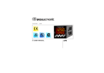
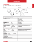
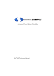
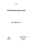
1605
1/16 DIN
Temperature Controller
Issue Date
January 1998
❒ USER’S MANUAL
0037-75342
Contents
Model Identification .................................................................................................................................... Page ii
Dimensions and Panel Cutout ............................................................................................................................1
Wiring ...........................................................................................................................................................................2
Hardware Setup .......................................................................................................................................................8
Configuration Procedure .................................................................................................................................... 10
Operator Mode ...................................................................................................................................................... 20
Display Functions .......................................................................................................................................... 20
Pushbutton Functions in Operator Mode ............................................................................................ 21
Operating Modes .......................................................................................................................................... 23
Instrument Status Indication .................................................................................................................... 26
Direct Access to Setpoint .......................................................................................................................... 27
SMART Function ........................................................................................................................................... 27
Operator Parameters ................................................................................................................................... 28
Error Messages ..................................................................................................................................................... 31
Warranty and Return ........................................................................................................................................... 33
Chromalox 1605 User's Manual
i
Model Identification
Model
1605
SMART Self-Tuning, Programmable 5-Segment Ramp/Soak Profile, 3 Outputs, Dual 4-Digit Display of
Process and Setpoint, Field Selectable Universal Thermocouple, RTD, Voltage or Current Inputs, AutoManual Control, Programmable Alarms, 0.1 Degree Display Resolution, IEC 801-4 Noise Immunity, IP65
and NEMA 4X Splashproof Faceplate.
Code
1
6
Output 1 - Heat or Cool
Relay, 3 Amps at 240 Vac
SSR Drive, 14V @ 20mA, Jumper Selectable
Code
Output 2 - Alarm or Event
1
Relay, 2 Amps at 240 Vac
Code
Output #3 - Alarm or End-of-Cycle Indicator
1
Relay, 2 Amps at 250 Vac
Code
3
5
1605 ii
1
1
1
3
Power Supply
100-240 Vac
24 Vac/dc
Code
0
Add to complete model number
0
Typical Model Number
Chromalox 1605 User's Manual
Mounting
Select a mounting location within the following
guidelines:
• Minimal vibration.
• An ambient temperature range between 32°F and
122°F (0°C and 50°C).
• Easy access to the rear of the controller.
• No corrosive gases (sulfuric gas, ammonia, etc.).
• No water or other fluid (i.e. condensation).
• Relative humidity of 20% to 80% non-condensing.
The controller can be mounted on a panel up to 0.591"
(15 mm) thick with a square cutout of 1.772" x 1.772"
(45 mm x 45 mm).
Panel surface texture must be better than 6.3 μmm.
Install the controller as follows:
1. Insert the 1605 controller in the gasket.
2. Insert the controller in the panel cutout.
3. Pushing the controller against the panel, slide the
mounting bracket on to the rear of the controller.
4. Tighten the mounting bracket screws.
5. To insure NEMA 4X/IP65 protection, make sure the
controller fits snugly within the cutout.
Dimensions and Panel Cutout
Figure 1
Controller Dimensions
The controller is shipped with a rubber panel gasket. To
assure the IP65 and NEMA 4 protection, insert the panel
gasket between the controller and the panel.
3.0
(75)
2.4
(60)
1.77
(45)
4.13
(105)
1.9
(48)
OUTPUT
1.77
(45)
1
2
3
MAN
REM
˚C
˚F
SMRT
SP2
NC
AN
FU
M
1600
1.9
(48)
Chromalox 1605 User’s Manual
1
Wiring
Wiring Guidelines
Sensor Inputs
Note:
Any external components (like Zener diodes, etc.)
connected between sensor and input terminals may cause
errors in measurement due to excessive and/or not
balanced line resistance or possible leakage currents.
NO
C
2
13
NO
3
14
15
4
5
TC Input
OUT 2/3
Figure 3
Thermocouple Input Wiring
OUT 3
+ 10
PWR LINE
10
12
OUT 2
100 / 240 Vac
T/C
9
+ LINEAR -
8
1
11
Logic Input
- SSR +
C
7
RTD
OUT 1
6
NO
Figure 2
Rear Terminal Connections
- 9
+ 10
- 9
2
Chromalox 1605 User’s Manual
Notes:
1. Do not run input wires with power cables.
2. For TC wiring use proper compensating cable (use
type J TC extension wire with type J TC
connections), preferably shielded.
3. Shielded cable should be grounded at one end only.
RTD Input Wiring
Notes:
1. Do not run input wires together with power cables.
2. Observe the line resistance; a high line resistance
may cause measurement errors.
3. When shielded cable is used, it should be grounded
at one side only to avoid ground loop currents.
4. The resistance of the 3 wires must be the same.
RTD Input
Linear Input
TC Inputs (continued)
Figure 5
mA, mV and V Inputs Wiring
Figure 4
RTD
RTD
10
+
mA
mV
or
9
-
10
+
V
mA
mV
9
8
9
10
8
9
-
10
or
V
G
Chromalox 1605 User’s Manual
3
Linear Input (continued)
Notes:
1. Do not run input wires together with power cables.
2 Pay attention to the line resistance; a high line
resistance may cause measurement errors.
3. When shielded cable is used, it should be grounded
at one side only to avoid ground loop currents.
4. The input impedance is equal to:
• Less than 5Ω for 20 mAdc input
• Greater than 1 MΩ for 60 mVdc input
• Greater than 400 KΩ for 5 Vdc and 10 Vdc input
Logic Inputs
Figure 6
Logic Inputs
14
15
Relay Outputs
Figure 7
Relay Outputs
1
OUT 1
The logic input is used to Start/Stop the ramp/soak
program using an external contact.
Safety Notes:
• Do not run logic input wiring with AC power cables.
• Use an external contact with a contact rating greater
than 0.5 mA, 5 Vdc.
• The controller needs 100 ms to recognize a contact
status variation.
• The logic inputs are NOT isolated from the
measuring input.
4
NO - OUT 2
2
C - OUT 2/3
NC - OUT 3
OUT 2
(AL1)
3
C
6
OUT 3
(AL2)
NO
7
Chromalox 1605 User’s Manual
Relay Outputs (continued)
All relay contacts are protected by varistor against
inductive loads with inductive components up to 0.5 A.
The OUT 1 contact rating is 3A/250Vac resistive load.
The OUT 2 and OUT 3 contact rating is 2A/250Vac
resistive load.
The number of operations is 1 x 10⁵ at specified rating.
Notes:
1. To avoid electric shock, connect power line at the
end of the wiring procedure.
2. For power connections use No 16 AWG or larger
wires rated for at last 75 °C.
3. Use copper conductors only.
4. Do not run input wires together with power cables.
Inductive Loads
Employing the following recommendations will help
avoid serious problems that may occur when relay outputs
are used with inductive loads.
High voltage transients may occur when switching
inductive loads. Through the internal contacts these
transients may introduce disturbances that can affect the
performance of the controller.
For all the outputs, the internal protection (varistor)
assures a correct protection up to 0.5 A of inductive
component.
The same problem may occur when a switch is used in
series with the internal contacts as shown in Figure 8.
Figure 8
External Switch in Series with the Internal Contact
C
R
Power
Line
Load
Chromalox 1605 User’s Manual
5
Inductive Loads (continued)
Warnings:
1. When a relay output is used to drive an inductive
load, it is suggested that you connect an external
snubber network (RC) across the terminals using
Chromalox P/N 0149-01305.
2. Do not run input wires together with power cables.
3. For TC wiring, use matching thermocouple
extension wire (i.e. Type J extension wire for Type J
thermocouple.
4. When using a shielded cable for input wires, the
shield should be grounded at one point only.
Voltage Outputs for SSR Drive
The SSR Drive Output is a time proportioning output.
Logic Level 0: Vout < 0-5 Vdc
Logic Level 1: 14V ± 20% @ 17mA
+24V ± 20% @ 1mA
Maximum = 17mA
Notes:
1. This output is not isolated. An external solid state
relay must be used to isolate the controller output
and power supply.
2. To determine Output #1 output type, check the tag
on your controller and compare it to the model
identification table on page ii.
Figure 9
SSR Drive Output Wiring
+
6
+
OUT 1
7
6
-
˜
Chromalox 1605 User’s Manual
Power Line and Grounding
Figure 10
Power Supply
N
4
Type
Current
Voltage
24 V AC/DC
T
500 mA
250 V
100/240 V AC
T
125 mA
250 V
When the fuse is damaged, it is advisable to verify the
power supply circuit. Return the controller to Chromalox
for test and verification.
Power Supply
100 to 240 Vac
or 24 Vac/Vdc
5
R (S, T)
Power supply
R (S, T)
N
Notes:
1. Before connecting the power line, check that the
voltage is correct (see Model Identification, pg. ii).
2. For supply connections use 16 AWG or larger wires
rated for at least 75 °C.
3. Use copper conductors only.
4. Do not run input wires with power cables.
5. Polarity does not matter for 24 Vdc wiring.
6. The power supply input is NOT fuse protected.
Please provide external fusing.
Chromalox 1605 User’s Manual
7. Safety requirements for permanently connected
equipment:
• Include a switch or circuit-breaker in the
installation.
• Place the switch in close proximity to the
equipment and within easy reach of the
operator.
• Mark the switch as the disconnecting device for
the equipment.
Note:
A single switch or circuit-breaker can drive more
than one controller.
8. When the NEUTRAL line is present, connect it to
terminal 4.
9. To avoid shock and possible controller damage,
connect power last.
7
Hardware Setup
1. Remove the controller from its case.
2. Locate the J106 jumper block on the long, outermost
circuit board as shown in the following figure.
3. Place the J106 jumper pairs in the desired open or
closed positions as shown in the Input Type
Selection table.
INPUT
TYPE
TC-RTD
60 mV
5V
10 V
20 mA
1-2
open
open
close
open
open
3-4
close
close
open
open
open
J106
5-6
open
open
close
close
open
7-8
open
open
open
open
close
Figure 11
Hardware Settings
2
4
6
8
10
1
3
5
7
9
J106
Input
Type
J102
Output 1
Contact
9-10
open
open
open
open
close
Note:
The unused jumper can be positioned on pins 5-7.
V101
4. Locate J102 jumper block.
5. To select the Output 1 contact, set J102 as follows:
8
Contact
NO (standard)
NC
J102
1-2
2-3
Open Position
Chromalox 1605 User’s Manual
General Operation
Figure 12
There are two setup modes for the 1605:
• Configuration Mode
• Operator Mode
In general, the Configuration Mode is the initial setup of
the controller when first installed. Input type and alarm
setup are examples of Configuration Mode settings. The
Operator Mode includes settings that might be adjusted
frequently with daily control operations such as setpoints
and PID parameters.
2
4
6
8
10
1
3
5
7
9
J106
Input
Type
J102
Output 1
Contact
Pushbutton Functions for
Configuration Procedure
FUNC = Must be pressed to store the new value of a
selected parameter and increments to the
next parameter.
MAN
= In Configuration Mode, scrolls parameters
back (in reverse order) without storing the
new parameter value.
V101
▲ = Increases the value of the selected parameter .
▼ = Decreases the value of the selected parameter.
Chromalox 1605 User’s Manual
Open Position
9
Configuration Procedure
1. Remove the controller from its case.
2. Set the dip switch V101 in open position
(see Figure 12).
3. Reinsert the controller.
4. Switch the controller ON. The display will show
COnF.
Note:
If “CAL” indication is immediately displayed, press the ▲
pushbutton to return to the configuration mode “CnF.”
5. Press s key and the lower display will show the
firmware version.
6. Push the FUNC key to start the configuration
procedure.
10
P1
0
1
2
3
4
5
6
7
8
9
10
11
12
13
14
15
= Input Type and Range
= TC
L
= TC
L
= TC
J
= TC
J
= TC
K
= TC
K
= TC
T
= TC
N
= TC
R
= TC
S
= RTD
Pt 100
= RTD
Pt 100
= Linear 0 to 60 mV
= Linear 12 to 60 mV
= Linear 0 to 20 mA
= Linear 4 to 20 mA
0 to +400.0°C
0 to +900°C
0 to +400.0°C
0 to +1000°C
0 to +400.0°C
0 to +1200°C
0 to +400.0°C
0 to +1400°C
0 to +1760°C
0 to +1760°C
-199.9 to +400.0
-200 to +800°C
Chromalox 1605 User’s Manual
P1 = Input Type and Range Value (continued)
P2 = Decimal Point Position
16 = Linear 0 to 5 V
17 = Linear 1 to 5 V
18 = Linear 0 to 10 V
19 = Linear 2 to 10 V
20 = TC
L
0 to +1650°F
21 = TC
J
0 to +1830°F
22 = TC
K
0 to +2190°F
23 = TC
T
0 to +750°F
24 = TC
N
0 to +2550°F
25 = TC
R
0 to +3200°F
26 = TC
S
0 to +3200°F
27 = RTD
Pt100
-199.9 to +400.0°F
28 = RTD
Pt100
-330 to +1470°F
Note:
Selecting P1 = 0, 2, 4, 6, 10 or 27, will automatically set
P32 = FLtr. For all the remaining ranges it will set P32 =
nOFL.
Available only when a linear input is selected (P1 = 12,
13, 14, 15, 16, 17, 18 or 19).
----. = No decimal figure.
---.- = One decimal figure.
--.-- = Two decimal figures.
-.--- = Three decimal figures.
Chromalox 1605 User’s Manual
P3 = Initial Scale Value
For linear inputs, programmable from -1999 to 4000.
For TC and RTD inputs, programmable within the input
range.
When this parameter is modified, rL parameter will be
realigned to it.
11
P4 = Full Scale Value
For linear inputs, programmable from -1999 to 4000.
For TC and RTD inputs, programmable within the input
range with the limits shown below.
When this parameter is modified, rH parameter will be
realigned to it.
The initial and full scale values determine the input
span which is used by the PID algorithm, the SMART
and the alarm functions.
Note:
The minimum input span (S = P4 - P3), in absolute
value, should be set as follows:
• For linear inputs, S ≥ 100 units.
• For TC input with °C readout, S ≥ 300°C.
• For TC input with °F readout, S ≥ 550°F.
• For RTD input with °C readout, S ≥ 100°C.
• For RTD input with °F readout, S ≥ 200°F.
P5 = Output 1 Type
rEL = Relay (the cycle time (CY1) will be
forced to 15s]
SSR = SSR [the cycle time (CY1) will be
forced to 4 s]
P6 = Output 1 Action
rEV = Reverse action (Heating action)
dir = Direct action (Cooling action)
Reverse
Direct
Input
Input
t
Output
Output
t
12
t
t
Chromalox 1605 User’s Manual
P7 = Output 2 Function
0
= Output not used
1
= Used as Alarm 1 output and Alarm 1 is
programmed as process alarm.
2
= Used as Alarm 1 output and Alarm 1 is
programmed as band alarm.
3
= Used as Alarm 1 output and Alarm 1 is
programmed as deviation alarm.
4
= Used as Event Output
Note:
Setting P7 = 4, the Out 2 assumes the logic state
programmed, for each region, with the EV1, EV2, EV3,
EV4 and EV5 operator parameters.
P8 = Alarm 1 Operating Mode
Available only when P7 is equal to 1, 2 or 3.
H.A. = High Alarm (outside for band alarm) with
automatic reset.
L.A. = Low Alarm (inside for band alarm) with
automatic reset.
H.L. = High Alarm (outside band) with manual reset.
L.L. = Low Alarm (inside band) with manual reset.
Chromalox 1605 User’s Manual
P9 = Program Start/Stop
0
= Start/Stop program driven by front
pushbutton.
1
= Start/Stop program driven by external contact.
P10 = Output 3 Function and controller
operation after execution of the last
programmed cycle.
0
= Output not used. At the end of the last cycle
the controller will go in STANDBY mode.
1
= Used as Alarm 2 output and Alarm 2 is
programmed as process alarm. At the end of
the last cycle the controller will go in
STANDBY mode.
2
= Used as Alarm 2 output and Alarm 2 is
programmed as band alarm. At the end of the
last cycle the controller will go in STANDBY
mode.
3
= Used as Alarm 2 output and Alarm 2 is
programmed as deviation alarm. At the end of
the last cycle the controller will go in
STANDBY mode.
4
= Used as End of Cycle Indicator. At the end of
the last cycle the controller will go in
STANDBY mode.
13
P10 = Output 3 Function (continued)
5
= Used as End of Cycle Indicator. At the end of
the last cycle the controller will operate as a
controller using the setpoint of interval #5, but
the setpoint can be changed via controller
pushbuttons.
Note:
If P10 is set to 4 or 5 (End of Cycle Indication) and the
controller is set to execute more than one program
cycle, the following may occur:
• The controller completes one of the intermediate
cycles. At the end of interval #5, Out 3 will be
forced in ON status for a time equal to the value
assigned to P11 parameter.
• The controller completes the last cycle (or a single
cycle has been programmed). At the end of interval
#5, Out 3 will be forced in ON status for a time
equal to the value assigned to P12 parameter. If
P12 is equal to “iNF,” the Out 3 remains in ON
condition until a new START command is executed.
14
P11 = End of the Intermediate Cycle Indicator
Time
Available only when P10 is equal to 4. From 0 to 60
seconds.
P12 = End of the last Cycle Indicator Time
Available only when P10 is equal to 4.
From 10 to 60 seconds. Above this limit, the display will
show “InF” and, at the end of the last programmed
cycle, the Out 3 is forced in ON condition until a new
START command is detected.
P13 = Alarm 2 Operating Mode
Available only when P10 is equal to 1, 2 or 3.
H.A. = High Alarm (outside for band alarm) with
automatic reset.
L.A. = Low Alarm (inside for band alarm) with
automatic reset.
H.L. = High Alarm (outside band) with manual reset.
L.L. = Low Alarm (inside band) with manual reset.
Chromalox 1605 User’s Manual
P14 = Setpoint Tracking on Ramp, Process
Below Setpoint
0 = Function not used.
From 1 to 400 digits for linear input ranges.
From 1 to 40°C for TC and RTD inputs with °C readout.
From 1 to 72°F for TC and RTD inputs with °F readout.
Note:
When this function is enabled, the controller calculates
the control error (SP - measured process value) and it
operates as follows:
• When the error is positive and its absolute value is
greater than P14 value, the controller stops the
ramp execution and operates as a controller with a
constant setpoint.
• When the control error is lower than the P14 value
or it becomes negative, the ramp execution will
restart.
Chromalox 1605 User’s Manual
P15 = Setpoint Tracking on Ramp, Process
Above Setpoint
0 = Function not used.
From 1 to 400 digits for linear input ranges.
From 1 to 40°C for TC and RTD inputs with °C readout.
From 1 to 72°F for TC and RTD inputs with °F readout.
Note:
When this function is enabled, the controller calculates
the control error (SP - measured process value) and it
operates as follows:
• When the error is negative and its absolute value is
greater than P15 value, the controller stops the
ramp execution and operates as a controller with a
constant setpoint.
• When the control error is lower than the P15 value
or it becomes positive, the ramp execution will
restart.
15
P16 = Guaranteed Soak
0 = Function not used.
From 1 to 100 digits for linear input ranges.
From 1 to 10°C for TC and RTD inputs with °C readout.
From 1 to 18°F for TC and RTD inputs with °F readout.
Note:
This parameter defines a symmetrical band (± P16)
around the soak.
When the measured value goes out of this band, the
soak time will be stopped. When the measured value
returns to within the band, the soak time will restart.
P17 = User Defined Security Code
0
= UNLOCKED. the controller is always unlocked
and all parameters can be modified.
1
= LOCKED. The controller is always locked and
no parameters (except for alarm manual reset)
can be modified (for SMART status see P25
parameter).
From 2 to 9999 = Select the security code (to be
stored), to be used in run time
(see “nn”), to LOCK/UNLOCK the
controller.
For alarm manual reset, the LOCK/UNLOCK condition
has no effect (for SMART status see P25).
16
End of Configuration
The configuration procedure is completed and the
controller shows “-.-.-.-.” on both displays.
To access the advanced configuration parameter proceed
as follows:
1. By pressing ▲ or ▼ pushbutton, set the code “263”
on the display.
2. Push the FUNC pushbutton.
P18 = Alarm 1 Action
Available only when P7 is different from 0 or 4.
dir = direct action (relay energized in alarm
condition)
rEV = reverse action (relay de-energized in alarm
condition)
P19 = Alarm 1 Inhibit Function
Available only when P7 is different from 0 or 4.
OFF = Alarm inhibit function disabled.
ON = Alarm inhibit function enabled.
Chromalox 1605 User’s Manual
Note:
If the alarm is programmed as band or deviation alarm,
this function inhibits the alarm condition after a setpoint
change or at controller startup until process variable
reaches the alarm threshold plus or minus hysteresis. If
the alarm is programmed as a process alarm, this
function inhibits the alarm condition at controller
startup until process variable reaches the alarm
threshold plus or minus hysteresis.
P20 = Alarm 2 Action
Available only when P10 is different from 0 to 4.
dir = direct action (relay energized in alarm
condition)
rEV = reverse action (relay de-energized in alarm
condition)
P21 = Alarm 2 Inhibit Function
Available only when P10 is different from 0 to 4.
OFF = Alarm Inhibit function disabled.
ON = Alarm Inhibit function enabled.
Note:
For more details on alarm inhibit function, see P19
parameter.
Chromalox 1605 User’s Manual
P22 = OFFSET Adjustment
This parameter allows you to set a constant OFFSET that
will be added to the measured value throughout the
readout range.
It is skipped for linear inputs:
• For readout ranges with decimal figure, P22 is
programmable from -19.9 to 19.9.
• For readout ranges without decimal figure, P22 is
programmable from -199 to 199.
Readout
P22
Real curve
Adjusted
Offset
curve
Input
17
P23 = Control Output Maximum Rate of Rise
Programmable from 1% to 10% of the output per
second.
Above 10%, the display will show “InF” meaning that no
ramp is imposed.
Note:
When an ON/OFF control action is selected, P23
parameter will be ignored.
P27 = Minimum Value of the Proportional Band
Calculated by the SMART Algorithm.
Programmable from 1.0% to P26 value.
P24 = Displayable Protected Parameters
This parameter is skipped when P17 = 0.
OFF = Protected parameters cannot be displayed.
ON = Protected parameters can be displayed.
P29 = Device Status at Controller Startup.
0 = The controller will startup in STANDBY mode.
WARNING:
When a hot start occurs (i.e. after a power supply
failure) the program execution will be aborted and
the controller will restart in STANDBY mode.
1 = It restarts in the same way it was left prior to
power shut down.
P25 = SMART Function
0 = SMART function disabled
1 = SMART function is NOT protected by the security
code.
2 = SMART function is protected by the security code.
P28 = Minimum Value of the Integral Time
Calculated by the SMART Algorithm.
Programmable from 20 seconds (00.20) to 2 minutes
(02.00).
P26 = Maximum Value of the Proportional Band
Calculated by the SMART Algorithm.
Programmable from P27 value to 100.0%.
18
Chromalox 1605 User’s Manual
Notes:
• If the controller was performing a ramp (interval 2
or 4), it aligns the operative setpoint to the actual
measured value and then it restarts the execution
of the ramp (up or down) with the programmed
gradient.
• If the controller was performing a soak (interval 1,
3 or 5), it divides the soak time in 4 quarters and
then it will restart from the beginning of the
quarter that was in execution prior to the power
shut down.
P30 = Integral Preload
Programmable from 0 to 100% of the output span.
P31 = Time-out Selection
This parameter allows the operator to set the time
duration of the time-out from parameter settings to
Normal Display Mode used by the controller during the
operator mode.
tn. 10 = 10 seconds
tn. 30 = 30 seconds
Chromalox 1605 User’s Manual
P32 = Digital filter on the Displayed Value
Applies to the displayed value a digital filter of the first
order with a time constant equal to:
-4 s for TC and RTD inputs
-2 s for linear inputs
noFL. = no filter
FLtr = filter enabled
P33 = Conditions for Output Safety Value
(% output on sensor failure)
0 = No safety value (“Standard” effect)
1 = Safety value applied when overrange or
underrange condition is detected.
2 = Safety value applied when overrange condition is
detected.
3 = Safety value applied when underrange condition is
detected.
P34 = Output Safety Value
This parameter is skipped when P33 = 0.
This value can be set from 0 to 100%.
(0 = OFF, 100% = full ON).
The configuration procedure is terminated and the
display returns to show “COnF”.
19
Operator Mode
Display Function
1. Remove the controller from its case.
The upper display shows the measured value while the
lower display shows:
• OFF when the controller is in STANDBY Mode
• the remaining time in Interval 1 (initial delay)
• the current setpoint during a ramp interval
• the remaining time during a soak interval
Figure 13
Operator Mode
To display the Percent Power Output on the lower
display:
• Push and hold the FUNC pushbutton for more than
3 seconds. The lower display will show “H” followed
by OUT 1 power value (from 0 to 100%).
• Push FUNC pushbutton again. The display will
return to “Normal Display Mode.”
Closed Position
When no pushbuttons are pressed during the time-out
(see P31), the display will automatically return in
“Normal Display Mode.”
2. Set the switch V101 in closed position.
3. Reinsert the controller and switch it ON.
To continuously display information on the lower display,
depress the ▲ or ▼ pushbuttons to remove the timeout.
If an error message, “Err 400” appears, simultaneously
press ▲ and ▼ pushbuttons to reset the display to the
normal mode.
To return to the “Normal Display Mode”, push FUNC
pushbutton again.
20
Chromalox 1605 User’s Manual
Indicators
°C
Process Variable is shown in degrees Celsius.
°F
Process Variable is shown in degrees
Fahrenheit.
SMRT Lit when the SMART algorithm is active.
OUT1 Lit when OUT 1 is ON.
OUT2 Lit when OUT 2 is ON, or alarm 1 is in alarm
condition (used as break event output).
OUT3 Lit when alarm 2 is in an alarm condition, or
when OUT 3 is used as a logic output (End of
Cycle) to indicate the end of cycle.
Other functions are shown by decimal points:
• When the SP2 decimal point is lit, SP2 is in
operation.
• When the MAN decimal point is flashing at
slow rate, it shows that the controller is in
MANUAL mode.
• RUN decimal point at the upper right of the
upper display is lit when:
- the ramp/soak program is running
- the controller is performing the 2 initial
intervals (Wait and Ramp to SP1) before
operating as a controller
Chromalox 1605 User’s Manual
Indicators (continued)
• The decimal point is flashing when:
- the ramp tracking or guaranteed soak
functions suspend the program execution
- an “out of range” on the measured value is
detected
Pushbutton Functions in Operator Mode
FUNC
= During parameter modification, FUNC
must be pressed to store the new value
of a selected parameter and
increments to the next parameter
(increasing order).
During program execution or when the
controller operates as a controller
(without program), pushing the FUNC
pushbutton for more than 3 seconds
will cause the lower display to show
“H.” followed by OUT 1 power value
(from 0 to 100%). Pushing FUNC
pushbutton again will return the
display to Normal Display Mode.
21
Pushbutton Functions in Operator Mode (continued)
RUN
▲
22
= When P9 = 0 and the controller is in
STANDBY mode, it starts the program
execution (when depressed for more
than 1 second).
When P9 = 0, during the program
execution, it aborts the program
execution (when depressed for more
than 5 seconds).
During parameter modification, it is
used to scroll back the parameters
without storing the new setting.
= During parameter modification,
increases in the value of the selected
parameter.
When the controller operates as a
controller, press ▲ to access setpoint
modification.
When the controller is in manual
(MAN) mode, press ▲ to increment the
output value.
▼
= During parameter modification,
pressing ▼ decreases the value of the
selected parameter.
When the controller operates as a
controller, press ▼ to access setpoint
modification.
When the controller is in manual
(MAN) mode, press ▼ to decrease the
output value.
▲ + FUNC = Are used to toggle from STANDBY
mode to MANUAL mode and back to
STANDBY
▲ + FUNC/
▼ + FUNC = During parameter modification they are
used to increase or decrease the value
of the selected parameter at higher
rate.
▼+▲
= When SMART function is disabled,
they are used to start the default
parameter loading procedure.
Note:
A 10 or 30 second time-out (see P31) can be selected.
If, during parameter modification, no pushbutton is
depressed for more than 10 (30) seconds, the controller
goes automatically to Normally Display Mode, and the
eventual modification of the last parameter will be lost.
Chromalox 1605 User’s Manual
• MODE A: STANDBY Mode
The controller operates as an indicator. The power output
is OFF and alarms are in no alarm status. The upper
display shows the process variable while the lower display
shows OFF. Only when the controller is in STANDBY
Mode is it possible to enable the MANUAL Mode
(MODE C).
• MODE B: RUN Mode
This phase can be started by depressing the RUN
pushbutton or by keeping the external contact closed for
more than 1 second (see P9). The RUN LED will be lit.
The controller operates as follows:
1. As a controller:
- Setting the SP1 soak time equal to infinite, the
controller performs the first 2 intervals (Wait and
Ramp to SP1) and then it will operate as a standard
controller (see Figure 14).
Chromalox 1605 User’s Manual
Figure 14
Setpoint
Stand
by
Wait
Soak 1
infinite
Stand
by
Wait
Ramp 1
The 1605 is a controller and programmer. This controller
can operate in 3 different modes:
Ramp 1
Operating Modes
Soak 1
infinite
SP
Ambient
Temperature
Power ON
RUN
Power OFF
Power ON
Time
RUN
Note:
When the controller operates as a controller, it is possible
to modify the setpoint (SP1) using the “Direct Access to
the Setpoint Modification” function or selecting the SP1
parameter and setting a new value.
23
Operating Modes (continued)
2. As a controller/programmer:
- The program is made up by 5 intervals:
1. Wait Interval, in which the power output is
OFF and alarms are in no alarm status. The time
duration of this interval is programmed by
“WAIT TIME” (dELY parameter. The upper
display shows the process variable while the
lower display shows (flashing) the time to reach
the end of this interval.
2. RAMP to SP1, the interval where at the
beginning of this interval the controller aligns
the operative setpoint to the actual measured
value and then it starts ramping toward SP1.
The gradient of this ramp is programmed by
“Grd 1” parameter.
During ramp the ramp tracking function may be
active (see P14 and P15).
The upper display shows the process variable
while the lower display shows the final setpoint
(SP1).
24
3. SOAK at SP1, the interval in which the
guaranteed soak feature may be active (see P16
parameter).
The upper display shows the process variable
while the lower display shows the time to reach
the end of this interval.
4. RAMP to SP2, the interval in which the
controller starts ramping from SP1 to SP2. The
gradient of this ramp is programmed by “Grd 2”
parameter
During ramp the ramp tracking function may be
active (see P14 and P15).
The upper display shows the process variable
while the lower display shows the final setpoint
(SP2).
The LED SP2 will be lit.
5. SOAK at SP2, the interval in which the
guaranteed soak feature may be active (see P16
parameter).
The upper display shows the process variable
while the lower display shows the time to reach
the end of this interval.
The LED SP2 will be lit.
Chromalox 1605 User’s Manual
Figure 16
Repetition with Wait
Operating Modes (continued)
Wait
Soak
1
Ramp 2
Soak
2
Ramp 1
Ramp 2
Ramp 1
Soak
1
SP
Ambient
Temperature
Power ON
RUN
Stand
by
Time
Figure 17
Repetition without Wait
SP
Setpoint
Stand
by
Ambient
Temperature
SP 2
Wait
Soak
1
Soak
2
Soak
1
Ramp 2
Soak
2
Stand
by
Wait
Ramp 1
Soak
1
SP 2
Ramp 2
Wait
Setpoint
Ramp 1
SP 2
Stand
by
Ramp 2
Setpoint
Ramp 1
- When this interval is completed, two different
situations may occur:
1. No more repetition cycles have been
programmed.
The controller returns to MODE A—
STANDBY Mode (see Figure 15).
Figure 15
No Repetition
SP
Power ON
RUN
2. One or more repetition cycles have been
programmed (see Figures 16 and 17).
Chromalox 1605 User’s Manual
Time
Ambient
Temperature
Power ON RUN
Time
25
Operating Modes (continued)
The next cycles restart from interval 2 (Ramp to SP1) or
from interval 1 (WAIT) according to the “dELY”
(ON/OFF) parameter setting.
Instrument Status Indication
The following table summarizes the LEDs and displays
status during each operative mode and interval.
• MODE C: MANUAL Mode
The MANUAL Mode can be enabled only when the
controller is in STANDBY Mode. MANUAL Mode is
enabled by pushing ▲ + FUNC pushbuttons.
Mode
SMART
LED
RUN
LED
SP2
LED (#)
MAN
LED
Lower
Display
STANDBY
Manual
OFF
OFF
OFF
OFF
OFF
OFF
OFF
Flash
“OFF”
Output %
When the controller is in MANUAL Mode, the lower
display shows “n.” followed by OUT 1 power output value
(from 0 to 100%).
RUN
Interval
Interval
Interval
Interval
Interval
OFF
ON (*)
ON (*)
ON (*)
ON (*)
ON
ON (**)
ON
ON
ON
OFF
OFF
OFF
ON (F)
ON (F)
OFF
OFF
OFF
OFF
OFF
Time (F)
Oper. SP
Time 1
Oper. SP
Time 2
The MAN decimal point of the lower display will be
flashing.
The power output can be modified by using ▲ and ▼
pushbuttons.
By depressing ▲ + FUNC pushbuttons again, the
controller returns to STANDBY Mode.
Note:
If a shutdown occurs when the controller is in restart in
MANUAL Mode at power up, it will restart in
MANUAL Mode with the same power output assigned to
the controller before the power shutdown.
26
1
2
3
4
5
(#) This LED will be flashing when the controller detects an
“out-of-range” of the measured value or when the tracking or
guaranteed soak functions suspend the program execution.
(*) When this function is enabled.
(**) When the controller operates as a controller, the
RUN LED will be OFF.
(F) It shows a flashing indication.
Chromalox 1605 User’s Manual
Direct Access to Setpoint
When the controller is in AUTO Mode and in Normal
Display Mode, you may modify the active setpoint (SP).
Push ▲ or ▼ for more than 2 seconds to change the
setpoint.
The new setpoint value becomes operative at the end of a
2 second time-out as long as no pushbuttons have been
pressed.
SMART Function
The SMART function automatically calculates the
optimum PID control parameters. To enable the SMART
function, push the FUNC pushbutton when the controller
is in the Normal Display Mode until “Snrt” is displayed.
Push ▲ and ▼ to set the display to ON, and press FUNC
again. The SMART LED will light. When the SMART
function is enabled, Pb, ti, and td are not displayed.
Chromalox 1605 User’s Manual
To disable the SMART function, push the FUNC
pushbutton until “Snrt” parameter is shown. Push ▲ and
▼ to set the display OFF, and push the FUNC
pushbutton. The controller maintains the last set of
SMART calculated control parameters and allows
parameters to be adjusted.
Notes:
1. The SMART enable/disable is protected by the user
defined security code (see P25).
2. During the first interval (WAIT), the SMART LED
will be off.
27
Operator Parameters
To adjust operator parameters, push the FUNC
pushbutton. The lower display shows the cue while the
upper display shows the value or the status (ON or OFF)
of the selected parameter.
Use the ▲ and ▼ pushbuttons. Set the desired value or
the desired status.
Notes:
1. The manual reset (n.rSt) of the alarms is always active.
2. When P24 = ON the controller is in MANUAL Mode
or in STANDBY Mode. Parameter modification is
limited by the software key status (see “nnn”
parameter) and by SMART status.
3. When P24 = ON and the controller operates as a
controller, it is possible to display but not to modify the
parameters dELY (hh,mm), EV1, SP1, Grd1, EV2, tln1,
EV3 while the parameters SP2, Grd2, EV4, tln2, EV5,
rPt and dELY (ON/OFF) will be skipped. Parameter
modification is limited by the software key status (see
“nnn” parameter).
28
4. When P24 = ON and the controller operates in RUN
Mode, it is possible to display but not to modify the
following parameters: dELY (hh,mm), EV1, SP1, Grd1,
EV2, tln1, EV3, SP2, Grd2, EV4, tln2, EV5, rPt and
dELY (ON/OFF). Parameter modification is limited by
the software key status (see “nnn” parameter).
Display and modification of the remaining parameters is
limited by the software key status (see “nnn” parameter)
and by SMART status.
Some of the following parameters may be skipped
according to the controller configuration.
Parameter Description
Snrt
SMART Status
The On or Off indication shows the actual
status of the SMART function. Set ON to
enable the SMART function. Set OFF to
disable the SMART function.
n.rSt
Manual Reset of the Alarms
This parameter is skipped if none of the
alarms have the manual reset function. Set ON
and then depress the FUNC key to reset the
alarms.
Chromalox 1605 User’s Manual
nnn
dELY
EV1
SP1
Grd1
EV2
tin1
Software Key for Parameter Protection
This parameter is skipped if P17 = 0 or 1
ON = the controller is in LOCK condition
OFF = the controller is in UNLOCK condition
When it is desired to switch from LOCK to
UNLOCK condition, set a value equal to P17.
When it is desired to switch from UNLOCK to
LOCK condition, set a value different from P17.
Wait Time (interval) in Hours and Minutes
From 00.00 to 99.59 (hh.mm).
Interval 1 Contact Status
ON = contact closed.
OFF = contact open.
First Setpoint
From rL to rH (in engineering units)
Gradient for Ramp to SP1 (interval 2)
From 1 to 500 digits per minute; above this
value the display will “InF” and the transfer
will be a step transfer.
Interval 2 Contact Status
ON = contact closed.
OFF = contact open.
Soak Time at SP1 (interval 3)
From 00.00 to 99.59 (hh.mm) or infinite (inF).
Chromalox 1605 User’s Manual
EV3
SP2
Grd2
EV4
tin 2
EV5
rPt
Interval 3 Contact Status
ON = contact closed.
OFF = contact open.
Second Setpoint
From rL to rH (in engineering units).
Gradient for Ramp to SP2 (Interval 4)
From 1 to 500 digits per minute; above this
value the display will show “InF” and the
transfer will be a step transfer.
Interval 4 Contact Status
ON = contact closed.
OFF = contact open.
Soak time at SP2
(Interval 5). Adjustable from 00.00 to 99.59
(hh.mm).
Interval 5 Contact Status
ON = contact closed.
OFF = contact open.
Number of Program Repetitions
From 0 (one execution only) to 100 + “InF”
(infinite executions).
Note: When the controller is in RUN Mode, it
shows the remaining program repetitions.
29
dELY
AL1
HSA1
AL2
HSA2
Pb
30
Wait Time Repetition
The first program cycle will never perform the
Wait Interval but, when rPt is different from 0,
it is possible to set dELY parameter in order to
start the next cycles from Interval 2 or from
Interval 1.
OFF = the next cycles will restart from Interval
2 (Ramp to SP1).
ON = the next cycles will restart from Interval
1 (Wait).
Alarm 1 Setpoint (in eng. units)
for process alarm: within P4 - P3 span.
For Band alarm: from 0 to 500.
For deviation alarm: from -500 to +500.
Alarm 1 Hysteresis
From 0.1 to 10.0% of P4 - P3 span.
Alarm 2 Setpoint (in eng. units).
(For range limits see AL1 parameter).
Alarm 2 Hysteresis
From 0.1 to 10.0% of P4 - P3 span.
Proportional Band
From 0.0 (ON/OFF control) to 100.0% of P4 P3 span.
Note: When controller is working with SMART
algorithm, Pb valueis limited by P26 and P27.
HYS
ti
td
CY1
rL
rH
OLH
Hysteresis of the ON/OFF Control
(when Pb = 0).
From 0.1 to 10.0% of P4 - P3 span.
Integral Time
This parameter is skipped if Pb = 0 (ON/OFF
action).
From 00.20 to 20.00 (in minutes and seconds
[mm.ss]). Above this value the display blanks
and integral action is excluded.
Note: When the controller is working with
SMART algorithm, the minimum value of the
integral time will be limited by P28 parameter.
Derivative Time
This parameter is skipped if Pb = 0 (ON/OFF
action).
From 00.00 to 10.00 (in minutes and seconds
[mm.ss]).
Cycle Time for output 1 range 1-200 sec
Setpoint Low Limit (in engineering units).
Setpoint High Limit (in engineering units).
Output High Limit (in % of the output).
Chromalox 1605 User’s Manual
Error Messages
Overrange, Underrange and Open Sensor Indications
The 1605 is capable of detecting a fault on the process
variable (Overrange, Underrange or Open Sensor).
When the process variable exceeds the span limits
established by configuration parameter P1, an Overrange
condition will be shown on display as show in the
following figure:
When P33 (output condition on error) is equal to 0, the
following conditions may occur:
• If an OVERRANGE is detected, the OUT 1 turns
OFF (if reverse acting) or ON (if direct acting).
• If an UNDERRANGE is detected, the OUT 1
turns ON (if reverse acting) or OFF
(if direct acting).
When P33 is different from zero and an out of range
condition is detected, the controller operates in
accordance with P33 and P34 parameters.
The open sensor can be signalled as:
An UNDERRANGE condition will be shown on display
as show in the following figure:
Chromalox 1605 User’s Manual
• for TC/mV input : OVERRANGE or
UNDERRANGE selected by a
solder jumper
• for RTD input : OVERRANGE
• for mA/V input : UNDERRANGE
31
Note: On the mA/V input the open sensor can be
detected only when the low end of range selected, has a
value greater than zero (4/20 mA or 1/5 V or 2/10 V)
On RTD input a special test is provided to signal
OVERRANGE when input resistance is less than 15 ohm
(Short circuit sensor detection).
Error Messages
The controller performs same self-diagnostic algorithm.
When an error is detected, the lower display shows the
“Err” indication while the upper display shows the error
code.
Error List
100
150
200
201-2xx
301
305
307
32
Write EEPROM error.
CPU error.
Write on protected memory.
Configuration parameter error. The two least
significant digit’s show the number of the
wrong parameter (ex. 209 Err shows an Error
on P9 parameter—see Note 1).
RTD input calibration error.
TC input calibration error.
RJ input calibration error.
311
313
315
400
500
502
510
Note:
Error on 20 mA input calibration.
Error on 5 V input calibration.
Error on 10 V input calibration.
Control parameters error (see Note 2).
Auto-zero error.
RJ error.
Error during calibration procedure.
1. When a configuration parameter error is
parameter only.
2. If an error 400 is detected, simultaneously push
the ▲ and ▼ pushbuttons for loading the
default parameters, then repeat control
parameter setting.
3. For all the other errors, contact your supplier.
Chromalox 1605 User’s Manual
Warranty And Limitation Of Remedy
And Reliability
Chromalox warrants only that the Products and parts
manufactured by Chromalox, when shipped, and the work
performed by Chromalox when performed, will meet all
applicable specification and other specific product and
work requirements (including those of performance), if
any, and will be free from defects in material and
workmanship under normal conditions of use. All claims
for defective or nonconforming (both hereinafter called
defective) Products, parts or work under this warranty
must be made in writing immediately upon discovery, and
in any event, within three (3) years from delivery,
provided, however all claims for defective Products and
parts must be made in writing no later than three (3)
years after shipment by Chromalox. Defective and
nonconforming items must be held by Chromalox’s
inspections and returned to the original f.o.b. point upon
request. THE FOREGOING IS EXPRESSLY IN LIEU OF
ALL OTHER WARRANTIES WHATSOEVER,
EXPRESS, IMPLIED AND STATUTORY,
INCLUDING, WITHOUT LIMITATION, THE
IMPLIED WARRANTIES OF MERCHANTABILITY
AND FITNESS FOR A PARTICULAR PURPOSE.
Chromalox 1605 User’s Manual
Notwithstanding the provisions of this WARRANTY
AND LIMITATIONS Clause, it is specifically understood
that Products and parts not manufactured and work not
performed by Chromalox are warranted only to the extent
and in the manner that the same are warranted to
Chromalox by Chromalox’s vendors, and then only to the
extent that Chromalox is reasonably able to enforce such
a warranty, it being understood Chromalox shall have no
obligation to initiate litigation unless buyer undertakes to
pay all cost and expenses therefore including but not
limited to attorney’s fees, and indemnifies Chromalox
against any liability to Chromalox’s vendors arising out of
such litigation.
Upon buyer’s submission of a claim as provided above and
in its substantiation, Chromalox shall at its option either
(i) repair or replace its Products, parts or work at the
original f.o.b. point of delivery or (ii) refund an equitable
portion of the purchase price.
The foregoing is Chromalox’s only obligation and buyer’s
exclusive remedy for breach of warranty, and is buyer’s
exclusive remedy against Chromalox for all claims arising
hereunder or relating hereto whether such claims are
based on breach of contract, tort (including negligence
and strict liability) or other theories, buyer’s failure
33
tosubmit a claim as provided above shall specifically
waive all claims for damages or other relief, including but
not limited to claims based on latent defects. In no event
shall buyer be entitled to incidental or consequential
damages and buyer should hold Chromalox harmless
therefrom. Any action by buyer arising hereunder or
relating hereto, whether based on breach of contract, tort
(including negligence and strict liability) or other
theories, must be commenced within three (3) years after
the date of shipment or it shall be barred.
Returns
Items returned to Chromalox Instruments and Controls
must be accompanied by a Return Authorization Number.
This number may be obtained from Chromalox
Instruments and Controls, Customer Service Department,
Telephone Number (615) 793-3900. It should appear on
the exterior of the shipping carton and on the shipping
documents. Defective items will be repaired or replaced at
our option, at no charge.
Return the defective part or product, freight prepaid, to:
Chromalox Instruments and Controls
1382 Heil-Quaker Blvd.
LaVergne, TN 37086-3536
34
Chromalox 1605 User’s Manual
Chromalox
®
INSTRUMENTS AND CONTROLS
1382 HEIL QUAKER BOULEVARD
LAVERGNE, TN 37086-3536
PHONE (615) 793-3900
FAX (615) 793-3563