1
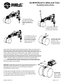
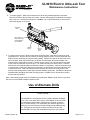
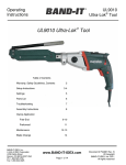
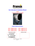
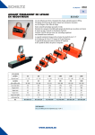
UL9010 Electric Ultra-Lok Tool
Operating Instructions
Warning:
Always wear safety glasses when operating this tool. Keep both hands
away from clamp being tensioned. Use common sense, squeezing
force of ¾” clamp can reach as high as 2 tons. Never attempt
to clamp objects which can shatter or otherwise cause
bodily harm.
Adapter
Clamp
Tail
Tension Block
Position
Viewing Slot
(also lubrication
syringe access)
Tension Block/
Tension Screw
Inside of slot
Band-It
Ultra-Lok
Tool
Drill
M04587
Actuator
Switch
Rotation
Reversing
Switch,
both sides
Clamp
M08288
Adapter
Clutch
Assembly
M03990
Buckle
Tool
Head
Slot
Band-It
Ultra-Lok
Preformed
Clamp
Tool Head
Mounting
Screws
Tighten to
100-130 INLBS, 4 places
Screw
#10-32 x
3/8 long
Direction of Rotation
Indicator Lights
(Right hand for tensioning)
(left hand for re-setting)
Impact / drill selector
set to drill
(drill bit symbol)
Tool
Adapter
Body
M07687
Screw
5/16-18 x
1 ½ long
Torque and
Speed Knobs
See below
Worn Brush
Indicator Light
Preset Torque Indicator Light
steady glow indicates tension has
been reached. Blinking light indicates
drill temperature protection circuit
has overloaded. Cut power to drill, let
it cool down, then proceed.
Indicator Arrow
Torque Control Knob
Speed Control Knob
Read inner scale only
Indicator Arrow
P44987 Revision “B“
Gear Selector
set to slow
(turtle symbol)
Indicator Arrow
Page 1 of 10
UL9010 Electric Ultra-Lok Tool
Operating Instructions
1. Read safety instructions and operator’s manual METABO electric drill. Check to make sure drill is properly set up for
use with Band-It Ultra-Lok tool as follows:
-----Drills spindle has adapter clutch (Band-It #M03990) installed in place of standard drill chuck.
-----Speed gear selector must be on slow (turtle setting).
-----Impact drive must be disengaged (twist drill symbol pointing forward).
3. To mount drill on tool: Use the two #10-32 x 3/8” screws supplied with tool to tighten tool adapter body to the tool.
Make sure that tool adapter body’s slit side is facing downward from tool. With adapter clamp on tool
adapter body, insert drill into back of tool through the adapter clamp. Turn drill manually to desired position in relation
to tool. Press the drill firmly into tool. Actuate drill if necessary to engage drill to tension screw. Tighten the 5/16-18 x 1
½” screw while keeping the drill firmly pressed against the tool. To remove drill from tool: loosen the 5/16-18 x 1 ½”
screw and pull drill away from the tool.
3. Plug drill into standard 115V AC, 60 Hz outlet, in the U.S.A. Rated Input = 8 amps (1010 watts).
4. This tool was designed for, and can only be used with, Band-It ¾” wide Ultra-Lok clamps. Do not attempt to use on
any other type of clamp, it may damage tool.
5. Setting up proper tension:
Recommended setting for most assemblies – torque number ‘5’ @ 800 rpm
Usable maximum (for extreme hose types) – torque number ‘7’ @800 rpm
If tension output of tool is too high, set drill to a lower torque number and/or speed.
Important: Changing speed setting will alter tension output. Drill switch must be depressed fully by the operator to
attain correct tension when installing clamps. Use speed control wheel’s inner scale (turtle symbol) to set speed.
Tension output may be somewhat different from tool to tool on same setting, depending on condition and wear of
internal components.
Important: When clamping a hose end, remember that a tighter clamp keeps the fitting more secure, but excess
tension could damage the hose. Fitting stem must have prominent barbs for proper retention inside the hose, but
must not be sharp to prevent cutting into the hose. Hose, fitting, and clamp must be compatible with each other or
fitting manufacturer or call Band-It.
Clamping objects other than hose requires similar precautions.
Caution: Improperly tightened clamps may result in dangerous assemblies, which could cause injuries or property
damage.
Caution: Abuse or use of a hose outside the manufacturers recommended conditions may cause it to quickly
deteriorate and become a safety hazard. This could result in serious injury or property damage. Inspect and test
hose assemblies frequently. Repair or replace at the slightest sign of damage or deterioration.
Using correctly sized clamps (diameter) will, in most cases, eliminate the need to pull on clamp tail more than once.
Tension block moves approximately 5”. On occasion, if needed, large size clamps can be installed by taking several
bites (clamp tail feeds out through back of tool). Position of tension block, containing gripper, can be monitored
through viewing holes just under cut-off handle. Tool features built-in, disengaging mechanism to prevent tension
screw from jamming up. Excessive use of this feature will wear clutch mechanism and/or tension screw out
prematurely.
P44987 Revision “B“
Page 2 of 10
UL9010 Electric Ultra-Lok Tool
Operating Instructions
1. Keep handle all the
way down when applying
tension to clamp tail.
Tighten clamp until drill
stalls.
2. Push handle all the way
forward to form lock. Do
not force past a solid stop.
3. Push handle all the way
down. Reverse drill and
feed clamp tail out of tool.
Do not force tool against
clamp, it may result in a
folded clamp tail.
4. Break away clamp
tail by bending it up
and down. Tap
down buckle shroud
to complete clamp.
Keep handle all the way down when applying clamps. Make sure tension block is
all the way forward against the tool head. Set the drill up for right-hand rotation.
Insert clamp tail fully into tool through the tool head. Position the clamp at intended
location and fully depress the actuator switch on drill. Gripper in tension block
automatically engages clamp tail. Tension is applied when tension block stalls
under load and red torque indicator light glows on drill. Push the handle all the way
forward to a solid stop to form a lock and cut off clamp tail. Check to see if lock on
clamp is adequate. Always tap down buckle shroud on completed clamps.
Return handle down. Reverse switch on drill. Feed excess band out of
tool, while tension block is returning to its original position. Reverse switch again
and tool is ready for the next clamp.
Important: if tension block comes near its end of travel, release actuator
switch and reverse drill to pull more on clamp tail. Excessive use of
disengaging clutch indicated by a loud ratcheting sound leads to
premature wear of tension screw.
If clamp does not get tight on first pull, reverse drill and reset tool for
more pull. When re-applying tension, be sure to leave approximately
1.5 inch gap between tool head and buckle to ensure adequate thread
engagement between tension block and screw.
P44987 Revision “B“
For more pull,
reset tool and
start 1.5 inches
from buckle to
tighten clamp.
Page 3 of 10
UL9010 Electric Ultra-Lok Tool
Operating Instructions
Inspect buckle on completed clamp and tap down buckle shroud.
FRONT VIEW
Completed Clamp
(Visually inspect lock)
Shear Surface
Buckle Shroud
Important: Visually inspect lock formed in
band as shown. If lock has slipped under
the sheared surface of the buckle, remove
clamp and install a new one at reduced
tension.
SIDE VIEW
Completed Clamp
Lock sheared in center and
formed inside shroud
Tap down buckle
shroud to complete
clamp
Applying clamps on soft, thick-walled hose: tension clamp as described on page 3.
Wait 10-15 seconds before lifting handle and forming lock. This allows hose to settle
under clamp (cold flow), after that, clamp may be tensioned more by squeezing
actuator switch on drill until red indicator light glows. Complete clamp as described on
page 3.
P44987 Revision “B“
Page 4 of 10
UL9010 Electric Ultra-Lok Tool
Assembly Instructions
Notes:
Apply Item 34 (Grease) to:
Item 4 (Cut off Cam)
Item 3 (Cutter Knife) at contact point with item 1 (Tool Head)
Item 27 (Spring) Before installation
Apply Item 35 (Grease) to:
Item 7 (Tension Screw) Threads and at Grooved end
Item 2 (Cutter Blade) Counter-bore only, after item 14 (Bearing Tip) has been
installed.
Tighten the following:
Item 24 (#10-32 Screw) to 60 – 70 in-lbs.
Item 23 (1/4-28 Screw) to 90 – 110 in-lbs.
Adjust Item 25 (Plunger) for positive detent action when item 6 (Handle) is
actuated.
35
34
33
32
31
30
29
28
27
26
25
24
23
22
21
20
19
18
17
16
15
14
13
12
11
10
9
8
7
6
5
4
3
2
1
Item
P44987 Revision “B“
C23187
I16387
S19787
M07987
M08087
J64387
M08187
M01487
A53587
A33887
M02487
M06187
J67287
M05787
M05687
M07587
M07487
M07387
M04387
M02287
M06587
M05387
M01388
M00287
M02387
M09187
M01787
M08887
M00987
M04687
M09087
M08987
M00687
M00787
M00587
Part Number
.03
.05
.01
2
4
2
4
1
2
1
2
4
4
2
1
2
1
1
1
1
1
1
2
1
1
1
1
1
1
1
1
1
1
1
1
Quan.
Lubricant, Black Moly, Hi-Temp (cc)
Lubricant, Super Lube w/ Teflon (cc)
Adhesive, Bonding, #415 (cc)
Threaded Insert, #10-32
Rivet, Blind, .125 X .328 Long
Pin, Spring, 3/16 X 5/8 Long
Washer, .128 ID X .238 OD
Pin, Dowel, ¼ Dia X 1.50 Long
Spring, Compression, .300 X 1.00 Long
Spring, Compression, .180 X .813 Long
Screw, Spring Plunger, ¼-20
Screw, Socket Head Cap, #10-32 X 3/8”
Screw, Socket Head Cap, ¼ X ½”
Screw, Socket Head Cap, ¼ X 1”
Grip, Textured, Gray
Wear Plate, Fin.
Body, Right, Finished, UL9000
Body, Left, Finished, UL9000
Tripper Bracket, Cast/Fin.
Tip, Load Bearing, Fin.
Ball, ¼” Diameter
Bearing Tip, Fin.
Pin, .187 Dia X 1.50 Long, Fin.
Roller, Cut-off, Fin.
Plate, Release, cast/fin.
Gripper Guide, UL2000
Plate, Back, Cast/Fin.
Gripper, UL2000
Tension Screw, Fin.
Handle, Cut-off, finished
Tension Block, Mach., UL2000
Cam, Cut-off, UL9000
Cutter Knife, UL001
Cutter Blade, UL001
Tool Head, Fin. UL9000
Description
Page 5 of 10
UL9010 Electric Ultra-Lok Tool
Assembly Instructions
9
Tension Gripper Assembly
35
7 35
Brush lubricant
evenly on
threads.
5
16
2 Places
17
27 34
Component
under spring
load when
assembled.
8
10
4 34
28
Lubricate
both sides
Tool Head Assembly
13
11
26
Component
under spring
load when
assembled.
34
22
2 Places
25
2 Places
13
12
1
3
See preceding pages for parts list
15 35
P44987 Revision “B“
14 35
2
Page 6 of 10
UL9010 Electric Ultra-Lok Tool
Assembly Instructions
21 33
2 Places
6
32
18
29
30
4 Places
2 Places
24
4 Places
20
2 Places
19
31
4 Places
23
4 Places
See preceding pages for parts list
P44987 Revision “B“
Page 7 of 10
UL9010 Electric Ultra-Lok Tool
Maintenance Instructions
1. Approximately every 500 clamps, lubricate tension screw with
molybdenum disulfide lubricant, or equivalent.
Make sure tension block is all the way forward against the tool head.
Remove cap from syringe and insert tip of syringe into slot on top of tool
body. Press the tip against the tension screw just behind the tension block
and squeeze out approximately ½” long bead of lubricant. Remove
syringe, and actuate tool without a clamp a couple of times to spread
lubricant evenly on tension screw.
To order more lubricant, specify Band-It #C23199
2. Every 500-1000 clamps, depending on tension setting, inspect and
repack front bearing with same lubricant. Turn load bearing tip and
small bearing tip around 180° for a new bearing surface.
Bearing Detail
Small Bearing Tip
item 14
Access Hole to push
out components (use
paper clip)
¼” Ball
item 15
Blade
item 2
Load Bearing Tip
item 16
Blade Cavity,
must be packed
with lubricant.
Tension
Screw
item 7
3. To gain access to bearing components: remove blade mounting
screws (2 places) and slide blade free. Paper clip may be used to
push bearing components out of blade. Wipe lubricant from
components. If ball or bearing tips appears heavily worn, replace with
new one. Note: ¼” ball is made from hard tungsten carbide material,
do not replace with regular ball bearing. (Smooth indention from ball
in the bearing tips is normal).
To re-assemble bearing components: wipe blade cavity clean. Push
small bearing tip into cavity. Apply lubricant to ball and push into
cavity and fill remaining space with lubricant. Push load bearing tip
firmly into blade, some lubricant will be squeezed out. Re-attach
blade to tool head, making sure that load bearing tip extends into
tension screw. While turning mounting screws into blade, push on
blade rearwards. Tighten screws to approximately 120 in-lbs.
Blade Mounting
Screws
item 22
4. When replacing worn blade, follow instructions above to properly reassemble bearing components.
P44987 Revision “B“
Page 8 of 10
UL9010 Electric Ultra-Lok Tool
Maintenance Instructions
5. To replace gripper: Make sure tension block is all the way forward against the tool head.
Remove one side of the tool body or the other, not both. Slide gripper out sideways and replace
with a new one. Re-attach tool body side. Caution: Do not push drill switch or move tension
block while gripper is out of tool.
Tool Head
item 1
Move tension
block all the way
forward against
the tool head
Gripper
item 8
Tension
Screw
item 7
6. To replace tension screw: Move tension block all the way back, using drill in tensioning mode
(right hand turn). Remove tool from drill by loosening clamping screw. Remove blade and load
bearing tip from tensioning screw (see bearing detail). Remove one side of the tool body or the
other, not both. Grasp the smooth barrel on tension screw and pull all the way forward until
tension block is against the tool head. If tension screw is stuck, use a punch and tap the center
of the screw from the back end of the tool. Turn tension screw out of tension block. Lubricate
new tension screw with Molybdenum Disulfide lubricant, or equivalent. Install new tension screw
in reverse order, making sure that back end of tension screw extends well beyond the back end
of the tension block. Push the assembly all the way back and extend to round portion of the
tension screw through holes on the tripper bracket and back guide plate. Reinstall tool body side.
Reinstall blade and tighten the blade mounting screws. Reattach tool to drill and drive tension
block all the way forward.
Note: Drills needing repair must be forwarded to an authorized ‘Metabo’ repair center in your area.
Be sure to remove Band-It adapter clutch from drill.
Use of Alternate Drills
CAUTION !
The UL9000 tool is designed to work mounted to Metabo drill Model
1015. Use of any other drills in place of the Metabo 1015 may result
in unsatisfactory performance, hazards to the operator and/or the
tool, or unsafe clamps. Use of alternate drills must be approved in
writing by the Vice-President of Product Engineering at Band-It-Idex,
Inc. Disregard of this caution voids the warranty of the tool and
releases Band-It of any and all liabilities arising from such misuses.
P44987 Revision “B“
Page 9 of 10
UL9010 Electric Ultra-Lok Tool
Trouble-Shooting
1. Lock slips down in buckle: Tighten blade mounting screws. If lock on clamp is still not adequate,
reduce tension on tool by setting torque control knob to a lower number or reduce speed of the drill.
(See “Setting up proper tension”)
2. Drill makes loud, rapid clicking noise: Make sure hammer drill setting is off on drill. (Hammer
symbol on selector knob pointing to back)
3. Drill makes whining noise when clamp gets tight: Safety clutch is dis-engaging inside the drill on
high torque setting (usually 9 or +). Turn torque control knob setting to a lower number and lubricate
tension screw.
4. Anti-Jam clutch between drill and tool releases prematurely: Make sure tool is fully seated on
drill (Loosen clamping screw and re-tighten while pressing tool into drill). If problem still remains,
replace tension screw (Band-It #M00987)
5. Note: To prevent over-travel clutch wear, do not over-use. When tensioning clamp, let drill switch go
as tension block nears its end of travel. Reverse drill and send tension block all the way
forward for a second pull on the band.
Band-It Tool Guarantee and Conditions
Band-It tools are guaranteed against
defective workmanship and/or materials for
a period of one year from date of purchase.
This guarantee is void if tools are altered or
abused in any manner, including lack of
lubrication, or used for any purpose or in any
way not specifically covered by the
instruction packed with each tool.
Any performance data published herein is
based on laboratory tests which cannot
duplicate conditions that may be
encountered in field installations. Such
conditions may vary results substantially
from those shown, such as abuse in
handling and installation; failure to follow
recommended handling and installation
practices; abnormal environmental
conditions; neglect of operating condition of
Band-It tools or non-recommended
combinations of Band-It products. Band-It
IDEX, Inc. cannot be responsible for
performance characteristics resulting from
such variables. Representations by any
person of performance data other than as
set forth herein or otherwise in writing by
Band-It IDEX, Inc. are unauthorized and are
at customers risk.
This is Band-It’s sole warranty and is in lieu
of all other warranties, expressed or implied,
which are hereby excluded, including in
particular all warranties of merchantability or
fitness for a particular purpose. Band-It
shall not be liable for any loss, damages or
expenses directly or indirectly related to the
use of its tools or from any other cause or
for consequential damages. It is expressly
understood that Band-It is not responsible
for damage or injury caused to other
products, property, or persons by reason of
the use of its tools.
Metabo Drill is covered solely by
the Metabo warranty as described in
the Metabo literature. Band-It does
not extend any warranty of any kind
to the drill.
Band-It IDEX, Inc. reserves the right to
change and/or improve any Band-It product
without notice.
Band-It products are available from your
local authorized Band-It distributor at prices
and terms established individually by them.
Consult your local authorized distributor for
immediate delivery from local stock.
Ultra-lok clamps and tools are covered under one or more of the following U.S.
patents: 5,123,350 5,303,571 5,322,091 5,452,523 5,127,446 5,483,998
other U.S. and foreign patents are pending.
BAND-IT-IDEX, INC
A Unit of IDEX Corp
P.O. Box 16307
Denver, Colorado 80216-0307 USA
1-188-525-0758
[email protected] / www.band-it-idex.com
P44987 Revision “B“
Page 10 of 10