1
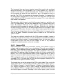
Senior Design II Paper
August 6, 2012
Group 4:
Michael Cooke
David Griffen
Whitney Keith
Edward Romero
Table of Contents
1.0
Executive Summary .................................................................................... 5
2.0
Project Description...................................................................................... 6
2.1
Motivation ................................................................................................ 6
2.2
Significance ............................................................................................. 6
2.3
Goals and Objectives .............................................................................. 7
2.3.1
High Efficiency and Low Cost ........................................................... 7
2.3.2
A High Signal-to-Noise Ratio (SNR) ................................................. 7
2.3.3
Mobility .............................................................................................. 8
2.3.4
User Friendly .................................................................................... 8
2.3.5
Comfortable and Lightweight Headset .............................................. 8
2.4
Requirements .......................................................................................... 8
2.4.1
Wireless Headphone Requirements ................................................. 8
2.4.2
Infrared Emitter and Detector Requirements .................................... 9
2.4.3
Triangulation ..................................................................................... 9
2.4.4
Processors ...................................................................................... 10
2.4.5
Graphical User Interface ................................................................. 10
2.5
Relevant Technologies .......................................................................... 10
2.5.1
3.0
Remotes ......................................................................................... 10
Hardware and Software Research ............................................................ 11
3.1
Wireless Headphones ........................................................................... 11
3.1.1
Types of Wireless Headphone Communication .............................. 11
3.1.2
Transmission Frequency for Headphones ...................................... 13
3.1.3
Wireless Headphone Transmission and Reception ........................ 14
3.1.4
Modulation ...................................................................................... 14
3.1.5
Antenna .......................................................................................... 16
3.2
Television Audio Adaptor....................................................................... 19
3.2.1
Audio Connections .......................................................................... 19
3.2.2
Analog to Digital (A/D) Conversion ................................................. 20
i|Page
3.2.3
Not using Analog to Digital (A/D) Conversion ................................. 21
3.2.4
Connecting the headphones to the television PCB......................... 21
3.2.5
Connection between the A/D boards to the Master Controller ........ 22
3.3
Headphone Tracking System ................................................................ 22
3.3.1
Triangulation ................................................................................... 22
3.3.2
IR Triangulation .............................................................................. 23
3.3.3
Camera vision Triangulation ........................................................... 24
3.3.4
RF Triangulation ............................................................................. 27
3.3.5
Transceivers ................................................................................... 30
3.3.6
Sensors for Tracking ...................................................................... 31
3.4
Graphical User Interface ....................................................................... 32
3.4.1
Application Types ........................................................................... 32
3.4.2
Application Display ......................................................................... 35
3.4.3
Tablet Specifications ...................................................................... 35
3.4.4
Android Interface and Data Storage ............................................... 37
3.4.5
Bluetooth Connection ..................................................................... 38
3.5
Microprocessors .................................................................................... 39
3.5.1
MSP430 .......................................................................................... 40
3.5.2
Atmega Series ................................................................................ 40
3.5.3
PIC micro-controller ........................................................................ 40
3.5.4
Stellaris Cortex-M3 ......................................................................... 41
3.5.5
Summary ........................................................................................ 41
3.6
Printed Circuit Board ............................................................................. 42
3.6.1
Parts and Acquisition ...................................................................... 42
3.6.2
Vendor and Assembly..................................................................... 44
4.0
Hardware and Software Design ................................................................ 47
4.1
Wireless Headphones ........................................................................... 47
4.1.1
Parts and Acquisition ...................................................................... 47
4.1.2
Receiver Module ............................................................................. 48
4.1.3
Speakers ........................................................................................ 52
ii | P a g e
4.1.4
4.2
Television Audio Adaptor....................................................................... 55
4.2.1
4.3
Infrared Receiver ............................................................................ 55
Headphone Tracking System ................................................................ 56
4.3.1
4.4
Subsystem Placement on Headphones .......................................... 54
Main Components and Design ........................................................ 56
Headphone-to-Television Communication............................................. 62
4.4.1
IR Emitter and Detector Design ...................................................... 63
4.4.2
Parts and Acquisition of IR Emitter and Detector ............................ 64
4.4.3
Infrared LED Design ....................................................................... 66
4.4.4
Infrared Detector Design ................................................................. 68
4.5
Audio Control and Switching Module ..................................................... 71
4.5.1
Multiplexers ..................................................................................... 71
4.5.2
Radio Frequency Module ................................................................ 72
4.5.3
Radio Frequency Antenna .............................................................. 73
4.5.4
RCA inputs from Televisions ........................................................... 73
4.5.5
Stellaris 8000 Series ....................................................................... 74
5.0
Software Design ....................................................................................... 75
5.1
Headphone Tracking System ................................................................ 75
5.1.1
Radio Frequency Collision Advance ............................................... 75
5.1.2
XBee Transceiver ........................................................................... 77
5.1.3
HP Module Software ....................................................................... 79
5.2
Headphone to Television Identification System ..................................... 80
5.2.1
Infrared LED Headphone Tag Programming .................................. 80
5.2.2
Infrared Receiver Headphone Identification Program ..................... 81
5.3
Android Tablet Application..................................................................... 83
5.3.1 Acquiring the Java JDK, Eclipse IDE, Android SDK and the ADT
Plugin 83
5.3.2
Application Design .......................................................................... 84
6.0
Design Summary ...................................................................................... 97
7.0
Project Testing ........................................................................................ 100
iii | P a g e
7.1
Wireless headphone Communication.................................................. 100
7.2
Audio Control and Switching Module .................................................. 101
7.3
Headphone Tracking System .............................................................. 102
7.4
Headphone to Television identification System ................................... 106
7.4.1
IR LED Testing ............................................................................. 106
7.4.2
Infrared Detector Testing .............................................................. 106
7.5
Android Application ............................................................................. 107
7.5.1
8.0
User Interfaces and Data Storage ................................................ 107
Administrative Content ........................................................................... 110
8.1
Milestone Discussion .......................................................................... 110
8.1.1
Senior Design I ............................................................................. 110
8.1.2
Senior Design II ............................................................................ 111
8.2
Budget and Finance Discussion .......................................................... 112
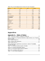
Appendices ...................................................................................................... 113
Appendix A – Table of Tables ....................................................................... 113
Appendix B – Table of Figures ...................................................................... 114
Appendix C – References ............................................................................. 115
iv | P a g e
1.0 Executive Summary
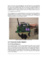
One of the most prevailing mediums in culture today is the Sports Medium. For
some people, it is a great past-time and for others, it dominates their lifestyles.
We have sports for every season: American Football for Fall, Basketball and
Hockey for Winter, Golf and Baseball for Spring, and much more. We also
celebrate each sport’s postseason games (aka playoffs) that crown a sport’s
team champion. Such sporting events began with actual attendance, then
listening to radio broadcasts and finally watching the events on television. To
accommodate the influx of so many teams (either professional or collegiate)
playing on television, many sports are broadcasted on specialized sports’
channels which are available through two methods: owning a cable or satellite
service to watch said games, or to go to Sports Bars.
Sports Bars host many of the available and desired sports games by having
many televisions displaying each game. The only disadvantage with this
structure is that only one game’s audio is broadcasted to the patrons. Usually the
audio is from a highly anticipated game; however, some patrons may be
dissatisfied because they wanted to watch a Soccer game during an American
Football game. The group has proposed a solution to this problem by having a
wireless headphone network with television audio input for sports bar application.
The headphones will autonomously change the television audio source
depending on which television the user wants to watch.
The group has also added extra features to the proposed solution. The idea is
that each of the headphones in the network can be tracked by using Radio
Frequency with a triangulation algorithm. The group projected this solution to the
problem of having lost headphones, stolen headphones, and defective
headphones. The user also requires the setup to be able to graphically show the
tracking of the headphones, a way to keep track of which customer is using
which headphone, and finally an easy to find user manual.
The group decided that having a mobile application will be able to satisfy the
costumer’s needs in having a graphical user interface were they can easily check
and modify the products properties. The application will graphically show the
mobility of the headphones in the owner’s facility. It will also allow for headphone
users to check in, which will allow an organization scheme to occur. This scheme
will help the owner to know which customer is using which headphone, hence
allowing them the possibility to track the user in case of faulty headphones, or
even theft. The application will also provide good documentation of the product,
which will give the owner a better user experience.
5|Page
2.0 Project Description
2.1 Motivation
The motivation for the project stems from the team members’ experiences at
sports bar establishments. Each of the members had a problem with watching
certain games and not being able to hear crucial audio snippets; what fouls
occurred, the sound effects from in-game interactions (tackling, yelling, hitting a
golf ball, etc.), and the sound from the surrounding environment (hearing the
chanting of the fans). The group wanted to find a way to enjoy listening to these
muted games and decided that it would not only benefit the group, but many
other patrons in the same predicament. The project is not something that the
group wants to work on, complete, and forget about, but hopefully the project will
inspire better designs and real-world use.
The team learned of the concept of SASER (Sound Amplification by Stimulated
Emission of Radiation) where this laser can emit high-frequency sound waves;
similar to optics and using lasers to emit light beams.[54] This concept
encouraged the team to look into ways to send audio from a television to a user.
However, since this technology is relatively new, the team had to find a way to
replicate something similar. The group realized the best way to grab this audio
was through a headset device (headphones) that would communicate with an
external device connected to a television that would send the desired audio to
the patron. Tackling the question of how to relay audio from multiple televisions
to a singular headset without manually setting a frequency or “channel” would
provide the group with quite a challenge that each team member was excited to
accept and solve.
Another reason the group chose to tackle this project was because of the
different communication techniques that would need to be researched and
implemented that the group wanted to learn how to use. The many classes the
team has taken have taught theories behind most of infrared, radio frequency,
and other wireless technology. However, finding a way to apply these to an
actual project would provide a challenge worthy enough to be considered a
Senior Design project. Also, utilizing a mobile platform to monitor and register
users would require knowledge of more specialized and advanced programming
languages than what some of the teammates were used to, but would be
beneficial for each of their future careers.
2.2 Significance
The “Eye Can Hear You” project is going to satisfy a variety of sports bar
customer’s audio experience. The project will be able to transmit television audio
to wireless headphones from the television the customer is viewing. Customers
will be able to autonomously choose what sport game or social media channel.
This will allow the customer to hear the sports games such as soccer, football,
6|Page
hockey, golf, basketball, and many others with quality audio. This project is a
new and innovative idea that will change the sports bar industry forever.
2.3 Goals and Objectives
The main goal of the “Eye Can Hear You” project is to allow patrons of sports
bars and restaurants to have the freedom to watch any televised sports game
without having to deal with environmental noise. What makes this different from
regular headphones these businesses use is to allow the patrons to manually
switch between televisions either through autonomous means or a signal pulse
button. This project would provide the customer with a mobile audio experience
as well as deliver quality sound. Security on this project must be enforced with a
device that could register and monitor these headsets to patrons that request
these proposed headsets. This device would be used by the staff.
The project’s objectives to satisfy the goals should follow these guidelines:
• High efficiency and low cost
• A high signal-to-noise ratio
• Mobility
• User Friendly
• Comfortable and lightweight headset.
2.3.1 High Efficiency and Low Cost
Since the project is being funded primarily by members of this team and no
sponsor, the equipment will need to be cheap so the team can afford them.
However, focus must be placed on equipment that will allow effective design of
the project and efficient implementation without being too cheap to work well. In
the following report, the group will compare and contrast different devices, mobile
platforms and development kits; choosing between cost effectiveness and
efficiency of the equipment. Due to the limited budget, priority lies with cheaper
devices. However, if a piece of equipment is a bit more expensive but more
effective in the overall design, it will be chosen instead.
2.3.2 A High Signal-to-Noise Ratio (SNR)
To satisfy the patrons of the sports establishment, it would be ideal for the project
design to have a high signal-to-noise ratio between each wireless system. This
would allow the patron to enjoy clear quality, as well as the overall system not
have to deal with conflicting signals that may scramble audio or control data. The
group will be researching different types of wireless systems (infrared, radio
frequency, Bluetooth and other wireless technology) that may benefit the project;
even combining a few that would operate on different frequency levels, avoiding
collisions.
7|Page
2.3.3 Mobility
Mobility is an important objective to the Eye Can Hear You project. The headset
itself cannot be tied down to a location, so it must be wireless. For instance, the
patron may want to continue to listen to the game as he or she heads to the
restroom, the system must be mobile enough that they can leave their table and
come back without losing the audio signal.
The monitoring device also requires mobility, because the sole users will be the
staff members of the sports bar establishment. The system also must operate on
a wireless system to retrieve location data. Since the device will also be
registering the patrons using the headsets, it would be ideal for it to be mobile so
the staff can retrieve registration from the patron at their table.
2.3.4 User Friendly
For the project to be user friendly, the patron should interact with the headset as
little as possible. The headset will either be autonomous or have a single button
to communicate with the external television device. This will allow the patron to
either have no role in selecting the television audio or have the patron send out a
signal with the touch of a finger.
Most staff who work at these establishments may not have a technical
background, so it would be beneficial for them to have a simple graphical user
interface (GUI); enforcing a user friendly environment on the device. To make
sure this occurs, the monitoring device should be programmed with as much
functionality behind the scenes as possible whilst having a smooth, seamless
and visually pleasing interface for the staff to operate.
2.3.5 Comfortable and Lightweight Headset
Since the headset needs to be mobile, it would benefit the project to design the
headset to be lightweight and comfortable. The headset must have as few,
lightweight components as possible while still maintaining its functionality. It
should also be padded and balanced so that the user will be comfortable wearing
the headset and moving around with it.
2.4 Requirements
2.4.1 Wireless Headphone Requirements
To optimize the customer’s audio experience within the sport restaurant, the
quality of audio received, audio transmission range and comfort will be
considered in selecting wireless headphones. Since a majority of people can
hear within the 20-20000 Hz range, the group requires the headphones to
produce a frequency bandwidth response within ±5% of the human audio range
to deliver good sound to the customer. The wireless headphones must have an
8|Page
audio transmission range of at least 100 feet, to allow customer mobility while still
receiving excellent sound. The size and form of the headphones must be
considered for customer comfort and mounting additional features. Over-ear
headphones are required to block out surrounding noise while using a thick
headband to support additional wireless headphone features. With this
consideration the weight of the headphones must be less than 1 lb. The battery
run time on the headphone is necessary efficiently last 12 hours, to support
constant customer use during the hours of operation of the sport restaurant while
requiring no more than 12 hours of charging time.
2.4.2 Infrared Emitter and Detector Requirements
The infrared emitter and detector used for headphone-to-television
communication must have coupled peak wavelength between 850-940 nm for
optimum efficiency. For the IR detector, the project requires a view angle of
about 120 degrees with a linear detection distance of at least 6m. The viewing
angle to find an IR signal can increase in range by placing more than one
detector side by side. As for the LED emitter, the larger the radiant intensity the
further the IR signal can travel. These requirements will allow the user to lock in
headphone-to-televisions identification throughout the restaurant. This
information was compiled from [1] and [2].
2.4.3 Triangulation
The Triangulation module of the project has to do with being able to track
multiple headsets in a given room. The idea is to be able to figure out where a
person is sitting with respect to the headphones which will tell us who the user, is
and if the headphones are still located in the room or bar. The triangulation
needs to be done inside a building without the use of GPS. It will have to be able
to track multiple moving headsets which will then be displayed in the Graphical
User Interface in the mobile device. The triangulation needs to be able to
calculate the exact (X, Y) coordinates of the headphone in a given room of
dimensions (W, L) provided by the user or vendor. The triangulation needs to tell
the difference from a movement of 1 meter minimum and a max movement of the
size of the room itself. It should be able to work if there is interference in external
objects moving around the room. The triangulation system should be able to
calculate the position of multiple headphones as close to real time as possible
while keeping the data processing to a minimum for low power consumption. The
triangulation system needs to work in extreme conditions from temperatures of
50 ℉ - 100 ℉. It should be able to work while tracking at least 20 headphones at
the same time. The triangulation needs to work even if there are walls in between
the detectors and the headphones. Overall the triangulation system needs to be
reliable, low cost, low power consumption, high triangulation range, and have
easy reprogramming options.
9|Page
2.4.4 Processors
The group will be working with several sensors and wireless transmission,
ranging from autonomous to a simple switch, so the group needs a reliable
micro-processor. The module to use should be of low cost and reliable, it should
be fast but have low power consumption, and it should be easy to program. The
micro-processor should have an internal clock, a low voltage powering system, at
least 3 serial ports, and at least 12 digital pins. It should have low noise for
wireless communication, and it should be pin through, since it is of lower cost to
populate the boards than having them populated. The micro-processor should
have high RAM, multiple baud rates for serial write/read, and have a good and
exact clock for dealing with transmission cycles.
2.4.5 Graphical User Interface
For the sports restaurant’s staff to monitor the location and status of their
headphone investment, it would be beneficial to have a Graphical User Interface
(GUI). This GUI must have the capability to render a map of the restaurant on a
smaller scale and be easy-to-read; a screen size of 7 inches to 10 inches would
suffice. The device running the interface must have access to a Bluetooth Stack
and be able to send data to and from a Bluetooth module; preferably with at least
Bluetooth Version 2.0. USB ports are necessary for any expansion or
communication requirements (talking with other devices). The device also needs
to have a high-end processor (preferably a dual-core processor) to quickly
update the location map and communicate to the master microcontroller. The
interface must be designed to be visually stimulating with buttons, text fields,
dropdown menus and a drag-and-drop method. It must also take care of all highend and complex requests from behind the scenes without the user being aware.
This would allow the user to fully interact with the system without requiring too
much technical knowledge. Location data must properly be displayed to within
half foot accuracy.
2.5 Relevant Technologies
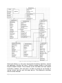
Within the realm of technological advancements, past inventions and system
protocols can be used in future designs as sub-systems to increase functionality
of a multi-system project. Past technologies may even be enhanced for longevity,
optimization, and functionality in new systems. This section will focus on
discussing relevant technologies used in similar applications to the Eye Can Hear
You project.
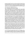
2.5.1 Remotes
Remotes are used in applications ranging from switching channels on a
television to controlling mobility options of remote control cars. Remotes pass
control information from devices such as buttons or joint stick through a wireless
communication to a receiving device to be processed. The commonly used
wireless communication systems in remotes are infrared and radio frequency.
10 | P a g e
Infrared communication is used in audio and video controls in most home
theaters. The remote works by pressing a button that pulses the infrared LED of
the remote at a particular pulse width modulation for a corresponding button. The
LED pulsing represents a binary code. The infrared detector located at the
source of the audio or video, receives the infrared pulses and decodes the signal
into a digital value to be sent to the microprocessor [61].The microprocessor
uses the digital inputs to control the electronic device’s operation [60]. Different
remote control developers use different protocol to define an on bit and off bit for
the IR LED and detector. The remote control protocol implementation in infrared
communication is unlimited.
Radio frequency communication is commonly used in car fobs and remote
control toy cars. A radio frequency remote works by transmitting radio waves that
correspond to a binary code for each button pressed [60]. The receiver decodes
the radio waves and outputs a digital signal to the microprocessor to carry out the
function received by the remote. Radio frequency communication in remote
controls has a similar application to infrared communication due to transmitting a
signal through a medium then receiving, decoding and actuating an operation.
Both communications have possible interference due to obstruction in the line of
sight of the infrared remote or other devices within range, transmitting radio
waves on the same frequency as the RF remote.
However the technology of the infrared remote implemented in the Eye Can Hear
You project will allow wireless data transfer within line of sight. This technology
will allow the project to identify which headphone is viewing a particular television
by sending an infrared pulsing identification signal from the headphones to the
television infrared detectors to decode.
3.0 Hardware and Software Research
3.1 Wireless Headphones
3.1.1 Types of Wireless Headphone Communication
The project Eye Can Hear You utilizes wireless headphones to receive audio
output from a television the user selects visually within a given environment. To
implement the idea of a network of wireless headphones and televisions, a type
of wireless headphone must be chosen to meet the project requirements. There
are three types of common wireless headphones, Bluetooth protocol, Infrared
(IR) and Radio Frequency (RF) defined by IEEE 802.15.4, used for various audio
applications. This research is to compare the different types of wireless
headphones to use for the Eye Can Hear You project to identify one that meets
the application need, audio quality and budget. The other half of the research
includes how to build and design wireless headphones.
11 | P a g e
3.1.1.1 Bluetooth Protocol
Bluetooth technology automatically connects Bluetooth devices wirelessly to one
another, enabling communication of data. Bluetooth sends data physically using
radio frequency and ensures agreement of the data sent through the devices by
using a standard level protocol [3]. The data transfer between two devices is
dependent on whether the devices are paired together in a network called a
piconet [3] and within transmission range of one another. Bluetooth is versatile in
creating network connections. A piconet can consist of up to 8 devices and one
device may be connected in several different piconets [4]. The most common
transmission range used in Bluetooth devices is 10 to 30 feet. The Bluetooth
radio frequency spectrum functions at 2.4-2.485 GHz which is an unlicensed
industrial, scientific and medical band (ISM). The protocol is a frequency hopping
spread spectrum that periodically hops over 79 frequencies within the
transmission range for a signal [5] at a rate of 1600 hops per second [4]. This
design was used to reduce interference of data transmission of devices within the
same spectrum. Bluetooth protocol also has a low power consumption of 2.5
mW and utilizes a power optimizing technology that turns off the power when not
in use.
Bluetooth headphones use Bluetooth technology to send audio wirelessly
through a medium to communicate with another device such as a television or
phone. For the project’s application of wireless headphones, versatility in the
number devices that can be connected to a Bluetooth network and the ability to
send signals without a line of sight makes this application desirable. However,
the transmission range of 30 feet makes this communication undesirable as the
mobile device needs to move around a restaurant environment and receive
quality audio in return as specified in requirements.
3.1.1.2 Infrared
Infrared headphones optically receive audio from a transmitter connected to an
audio source. The transmitter receives audio from the source and outputs the
sound digitally in a series of pulses through an infrared LED. As long as the
beam of infrared light is not blocked, the receiver on the headphones will use an
infrared LED to output an electrical pulse when the infrared light hits the cell. The
electrical pulses are translated to audio signals by the receiver which is amplified
and played through the headphones [6].
An infrared headphone has a transmission range of about 21 feet [7] from the
transmitter and also requires line of sight to transmit the audio. Due to user
mobility around the restaurant and possible obstructions within a busy
environment, infrared headphones are not the preferred wireless headphones for
the application.
12 | P a g e
3.1.1.3 Radio Frequency
RF headphones are exactly what the title describes, headphones that receive
audio from a transmitter via radio frequencies. Since RF broadcasts the full audio
spectrum the quality of sound is very good. These headphones also allow the
user mobility with a large transmission range of 100 to 300 feet. The user is able
to move from room to room since RF transmits through walls. Some of the
disadvantages of RF headphones is the likelihood of interference with other
electronic devices that emit electromagnetic waves intentionally and
unintentionally within the limited RF spectrum [8]. Another disadvantage of RF
headphones is the cost which can become expensive as the quality of sound is
improved.
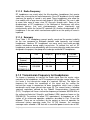
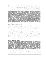
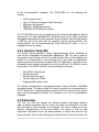
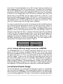
3.1.1.4 Summary
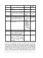
From Table 1, RF headphones present quality sound and the greatest mobility
for the user compared to Bluetooth protocol radio frequency and infrared
headphones. However RF headphones are more costly and could possible
receive interference during audio transmission. To combat the cost of RF
headphones and ensure compatibility with the master television audio transmitter
designed in the project, the group will also design and build RF headphones.
Bluetooth
Protocol
Infrared
Radio
Frequency
(IEEE802.15.4)
Cost
Range (ft)
$35-$150
10-30
$20-$80
21-30
$30-$300
100-300
Line of Sight
Possible
Interference
X
X
X
Table 1: Summary of wireless headphone comparison
3.1.2 Transmission Frequency for Headphones
To choose a frequency to transmit the audio signal from the master microcontroller to the headphones via RF the group must consider several factors. The
first factor is the transmission range of a required 100 feet. The higher the
frequency the shorter the wavelength of the signal and the smaller the
transmission range in comparison to lower frequencies which have a higher
wavelength and a larger transmission range [9]. The second factor is following
spectrum regulations defined by the Federal Communications Commission
(FCC). The project will have a transmitter frequency of between 902-928 MHz in
the unlicensed Industrial, Scientific, and Medical (ISM) spectrum known as the
ISM-900 [9]. To continue to follow FCC requirements, to broadcast on a FM
station as an unlicensed operation, guidelines described in Part 15 must be
followed. “There are no restrictions on the content or hours of operation for
unlicensed stations operating under Part 15.”[10] However, the maximum
coverage radius allowed is 200 feet with a maximum power transmission of 0.01
13 | P a g e
mW for FM broadcasting. This guideline meets the Eye Can Hear You project’s
transmission range requirement of 100 feet [10].
It is important not to pick up two signals on the same frequency, otherwise the
signals will merge and it will be difficult to separate one from another [9]. With the
advancement of wireless technologies, it is likely to have interference of signals
due to other devices emitting a wave at the same frequency within the same
transmission range. If this occurs, interference will be combated by increasing
the transmission power of the signal. Due to the constant change in wireless
electronic devices brought into the restaurant environment by customers and
electronic devices currently used in the restaurant, precautions must be taken
when designing and testing the wireless communication system.
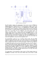
3.1.3 Wireless Headphone Transmission and Reception
Understanding the operation of how audio is transmitted and received wirelessly
will aid in the design of the wireless headphone reception and audio transmission
from the master microcontroller. This section will focus on signal processing from
an audio source to an audio output using radio frequency.
For the transmitting system, an audio source must interface with a radio
frequency transceiver or transmitter to wirelessly stream audio. The transceiver
then connects to a radio frequency amplifier to increase signal strength before
propagating the signal via an antenna. The receiving system receives the signal
through an antenna, then sends the signal through a low noise amplifier to
increase signal strength while producing little noise as possible. Any noise
produced by the amplifier can significantly distort the audio in comparison to
noise introduced in the later stages of signal processing. The signal from the low
noise amplifier is fed into a wireless transceiver then connected to the
microprocessor where manipulations of the signal may be calculated through
algorithms. Next the signal is converted from digital to analog in order to operate
the wireless headphones. But before the audio reaches the headphone’s
speakers it is amplified for a higher powered signal [52].
3.1.4 Modulation
Problems arise when transmitting audio wirelessly due to the low frequencies of
the human voice. The lower the frequency of a signal, the longer the wavelength
and the more likely attenuation will occur when the signal travels over a long
distance. Therefore, if the message signal can be transformed into a higher
frequency signal, less attenuation will occur as the signal travels. This process of
converting an original message signal into a carrier signal at a higher frequency
is called modulation. However the information of the original message must be
sent through the carrier signal. There are two types of modulation, analog
modulation and digital modulation that varies the parameters of the carrier signal
to include the information of the message signal [55].
14 | P a g e
3.1.4.1 Analog Modulation
Analog modulation consists of varying the amplitude, frequency or phase of the
carrier sinusoidal signal as the message signal’s properties of amplitude,
frequency and phase change. The three common types of analog modulation are
Amplitude Modulation (AM), Frequency Modulation (FM) and Phase Modulation
(PM). AM alters the carrier amplitude simultaneously as the amplitude of the
message signal changes. AM is the easiest to implement in the hardware design
of a transmitter and receiver as well as being less expensive in comparison to the
other analog modulation methods. FM alters the carrier signal’s frequency
simultaneously as the amplitude of the message signal varies. PM is the
alternation of the carrier signal’s phase with respect to the message signal’s
amplitude [55].
3.1.4.2 Digital Modulation
Digital modulation unlike analog modulation has two set amplitude levels of a
high and low value. The three common types of digital modulation are Amplitude
Shift Key (ASK), Frequency Shift Key (FSK) and Phase Shift Key (PSK). The
ASK is also known as the on-off keying (OOK) since a sinusoidal carrier signal is
present when the message signal is ‘high’ and the carrier is not present when the
message signal is ‘low’. The carrier signal will be comprised of bursts of
sinusoidal waves between deadlines. The FSK alters the frequency of the carrier
waveform depending on the high or low value of the message signal [55]. When
the message signal is ‘high’ the carrier signal will have one frequency value and
when the message signal is ‘low’ the carrier signal will have another frequency
value. The change of frequency within the carrier signal occurs at the same time
the binary value in the message signal changes from high or low and low to high.
Lastly, PSK alters the carrier signal to represent the message signal by changing
the phase of the carrier signal with respect to the ‘high’ and ‘low’ value of the
message signal. When the message signal is ‘high’, a 90° shift is made is one
direction and when the message signal is ‘low’, a 90° shift is made in another
direction [56].
3.1.4.3 Modulation Comparison and Conclusion
These modulation methods for digital and analog signals are used in many
transmitters and the associated demodulation methods used in the receivers.
This portion of the research compares the accuracy and cost of audio modulation
using the different analog and digital modulation methods. When comparing
analog modulation to digital modulation, digital modulation has a higher accuracy
of data transmitted than analog. This occurs because noise within the frequency
range of an analog carrier signal can become mixed in, distorting the signal
transmitted. However digital demodulation is recognized by a discrete value of
1’s or 0’s decreasing the likelihood of receiving noise in the signal. To implement
the method of digital modulation in hardware, it is more costly and complex. Most
signals, such as sound is analog. So to transmit analog signals using digital
modulation, the signal must be converted from analog to digital to transmit then
15 | P a g e
converted back to analog from digital after transmitted through the medium. This
process increases the amount of hardware involved in processing the signal,
therefore increasing the cost [57]. After evaluating the two main types of
modulation, the project chose to implement analog modulation. Since the audio
received from the television is an analog signal, it is cost efficient to transmit the
audio using an analog modulation technique. With the audio transmitting short
distance, less noise will occur on the signal externally. However precautions in
filtering out internal noise will be implemented when designing and connecting
the audio transmitters and receivers in the PCB layout.
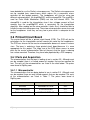
Since the group has decided to use analog modulation for the radio frequency
transmitters and receivers, the group must evaluate the efficiency and cost of the
analog modulation methods. In Table 2, a detailed evaluation of AM versus FM is
used to determine decide which method would be best to use in the project.
Analog Modulation (AM)
Easier to implement than FM since
the carrier signal’s amplitude can
directly influence the speakers audio
output.
Signal may be distorted by weather
Transmit one audio channel
Greater range than FM
Frequency Modulation (FM)
Sound quality is not degraded further
from the transmission base.
Signal is less likely to degrade in
comparison to AM due to
environmental factors being less
likely to affect frequency
Transmit two audio channels at once
for right and left speakers. Increases
audio experience.
Range of about 50 miles
Table 2: Comparison of Amplitude Modulation implementation versus Frequency Modulation [57]
In summary, the properties of Frequency Modulation best fit the project
objectives of delivering an enjoyable audio experience to the customers. Since
the radio frequency transmission will occur within the sports bar, the difference
between AM and FM range will not be considered along with the possible
distortion occurred by environmental factors due to the weather when coming to
a conclusion. However since FM has a higher quality sound demodulated than
AM, the project will use radio frequency FM. With the progression of technology,
even though AM consists of a simpler signal processing hardware than FM, the
price deviation is very little [57].
3.1.5 Antenna
The performance of the transmitter and receiver modules relies on the antenna
choice and specifications on each end of the wireless communication. When
transmitting an audio signal, FCC regulation determines the maximum output
power for the unlicensed radio frequency spectrum the group is broadcasting in.
16 | P a g e
Therefore consideration of the antenna type with respect to the output power of
the transmitter module needs to be considered. According to the transmitter
module datasheet of TXM-900-HP3-PPS, “Linx transmitter modules typically
have an output power that is significantly higher than the legal limits.” With this
consideration, Linx suggests using an “ineffiecint antenna” to output the
maximum output power for the range of the projects application. The company’s
second suggestion was to use an “efficient antenna” and attenuate the signal to
reduce the signal to the legal output power. These considerations will be used
when comparing antennas to work with the Linx HP3 transmitter module. For an
antenna on the receiving end of the signal, FCC requirements do not restrict the
properties of the antenna. To reduce noise from distorting the carrier signal
received by the antenna, the antenna must be geared towards the frequency of
the carrier signal. This will decrease the likelihood of the receiving antenna
including frequencies outside of the specified radio frequency application for the
project. The group must also consider the importance of finding a balance for a
realistic signal reception range within budget and use within the Eye Can Hear
You project.
3.1.5.1 Antenna Placement
When physically implementing an antenna in the design process there are
guidelines suggested by Linx Technologies to consider. It is suggested to
position an antenna’s shaft and tip in an upward position at a right angle away
from objects such as metal that could cause an inaccurate read of the carrier
signal. Linx Technologies also suggests when implementing an internal antenna
as the group will be doing, to position the antenna on the PCB so that it is away
from “transformers, batteries, PCB tracks, and ground planes” that could cause
detuning. For future arrangement of the circuit the RF transmitters and RF
receivers with the connected antenna will be placed on the outer edge of the
PCB to ensure the unlikely event of detuning. Once again for PCB design Linx
Technologies advices creating a ground plane to place the antenna on to
increase the optimum performance from the antenna.
3.1.5.2 Antenna Types
The group must now consider the different antennas types and properties that
will meet the radio frequency power output restrictions by the FCC for signal
transmission, and the frequency bandwidth as well as detection range need for
signal reception. The group must also consider the antenna cost and the possible
implementation difficulty between the antenna and the transmitter or receiver
modules. There are two types of antenna types considered by the group, whip
and loop. The whip antenna is most commonly used in radio frequency
applications. The whip antenna ranges from the simplistic application of a wire
connected to the back of clock radios to the manufactured antennas used in
handheld walkie talkies. The whip antennas come in full wavelength, half
wavelength or quarter wavelength antenna. Linx Technologies suggests using a
quarter wavelength antenna for their modules due to “the size and natural
17 | P a g e
radiation resistance” of the antenna. The loop antenna is however low in cost in
comparison to the whip antenna since they are printed on the PCB. With printing
the loop antenna on the PCB there are possible interferences due to PCB
elements such as capacitors within the antenna’s range. For the project
designing a loop antenna on the PCB would be time consuming due to the
complexity of the design. After comparing the two properties and implantation of
the antennas within the project’s design, the group chose to use a whip antenna
of a quarter wavelength as suggested by Linx Technologies.
3.1.5.3 Antenna Properties
When the group chooses a particular whip antenna, a few antenna parameters
must be taking into consideration for the project applications. The group will
consider the gain, polarization and impedance. The gain is important when
choosing the antenna for transmitter module. The gain may need to be negative
in order to compensate for the higher power output of the transmitter module.
Next, the polarizations of both antennas for the transmitter and receiver must be
compatible. This means that if the transmitter is a vertical whip then the receiver
must also have a vertical polarization to ensure efficient communication in the
wireless system. Lastly, the impedance of the antenna must match the
impedance of the transmitter or receiver for the correct power to be supplied to
the antenna. Also the orientation of the antenna with respect to ground will
change the impedance of the antenna. Therefore in the design process and
practical use within the Eye Can Hear You project it is important to place the
antenna to avoid object interference and possible disorientation due to customer
use. This will be implemented by placing the antenna 90 degrees from the
ground plane.
Another property to consider is the whip antenna length calculated by using the
formula:
=
L represents the length measured in inches for the quarter wave length and the f
is the operating frequency in MHz [58]. The length is defined by where the
antenna departs from ‘ground’ to the point of transmission. The constant k in the
formula is specific to a quarter wavelength antenna, which can be found using
the formula below.
= .95 = 71.25 = 2952ℎ
4 ∙ 1
In this formula c represents the speed of light in a vacuum (299,792,458 m/s)
which is the distance a radio wavelength of 1Hz travels in 1s. The speed of light
is multiplied by ¼ since this whip antenna is specific for a quarter wave antenna.
The speed of light is divided by 1,000,000 so the constant k is measured in
18 | P a g e
megahertz. Lastly c is multiplied by .95 which is a standard approximation of the
antenna’s length due to the ratio of antenna wire to wavelength [69]. This
constant formula implemented with the previous formula where the desired
frequency in MHz is 900, the length of the antenna is calculated to be 3.28
inches. The associated length of the antenna increases with when it is connected
to the transmitter with a wire [58]. A ground plane will be implemented to
decrease transmission and reception of signal noise.
3.1.5.4 Part Choice
After discussing the type of antenna that will be used as well as the antenna
properties to consider with the transmitter and receiver, the group choose a
quarter wave length antenna supplied by Linx Technologies (part number: ANT916_CW-QW). The antenna has a frequency range of 865-965 MHz that meets
the application, with a RP-SMA connector to stay within Part 15 of the FCC
regulations. The antenna has an impedance of 50 Ω that matches the HP3
transmitter and receiver impedance. This antenna has a low cost of $6.75 which
fits within the group’s budget.
3.2 Television Audio Adaptor
3.2.1 Audio Connections
There are several different approached to transmit the audio from the televisions
to the headphones. The audio would have to be routed from the televisions and
into a microcontroller. The microcontroller would then transmit the data to a
master microcontroller. The methods to transfer the sound to the microcontroller
are Sony/Philips Digital Interconnect Format (S/PDIF), HDMI, and RCA.
3.2.1.1 Sony/Philips Digital Interconnect Format (S/PDIF)
S/PDIF is a special digital audio connection for most receivers, TVs, stereos, and
movie devices.[11] It was invented by Sony and Philips to create a high definition
sound that would replace analog sound connectors. The cable used for this
connection was either a fiber optic cable or a coaxial cable. For the project, this
presented a problem. Older televisions do not have digital audio connections. It is
not financially sound to go buy newer televisions when the project already has
older ones donated to the project.
3.2.1.2 HDMI
High-Definition Multimedia Interface (HDMI) is a newer technology that
eliminates many other cables as well as providing a clearer sound and video than
older technologies.[12] However, this technology is not cost efficient for the
project or compatible with the donated televisions. The cables alone are over
$20. There are other complications with the technology as well. With HDMI, the
video is included with the audio. Since the headphones receive only audio,
19 | P a g e
separating the audio from the video stream will increase the workload of the
team.
3.2.1.3 RCA
Radio Corporation of America introduced RCA in the 1940’s for radio
phonograph consoles. The concept is still the same; however the technology has
advanced somewhat since then. RCA adapters have been in home audio/video
equipment since the 50’s. In fact, almost all televisions today still have RCA
adapters. This is a large reason for the selection of using RCA connectors in the
project. The televisions that have been donated to the project are older and do
not have HDMI or digital audio. RCA cables and adapters are certainly much
cheaper than HDMI. The analog output from the televisions is all that is needed
to transfer the sound to the headphones.
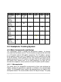
3.2.2 Analog to Digital (A/D) Conversion
The main function of the television PCB will be to convert the data coming from
the television into digital data. Since the team is going with RCA (an analog audio
output), the information must be converted into digital in order to transmit it to the
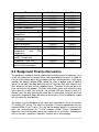
master microcontroller. On Digikey.com the parts range from $3.83-$9.42.
Luckily, all of the microcontrollers can be sampled and cost will not be an issue.
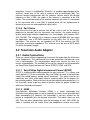
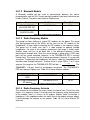
3.2.2.1 MSP 430
As shown in the Table 3, the MSP430 has 8 pins that are devoted to converting
analog to digital [13]. After the microcontroller converts it to digital audio, the
microcontroller will then prepare it for serial transmission to the master
microcontroller. Luckily, the headphones will convert the sound back to analog
for the user to hear the televisions.
Pin Number
2
3
4
5
6
59
60
61
Pin Type
P6.3
P6.4
P6.5
P6.6
P6.7
P6.0
P6.1
P6.2
Table 3: MSP430 A/D Pins
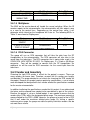
3.2.2.2 Stellaris ARM Cortex LM3S1110
Another Microprocessor available to for this project is the Stellaris ARM Cortex.
The advantage of the Stellaris is the 32-bit ARM Cortex M3 Processor Core.[14]
The Stellaris provides more processing power than the ATmega or the MSP 430.
As shown in Table 4, the Stellaris has two Analog Comparators. The Analog
20 | P a g e
Comparators will take in the two analog RCA inputs and output a discrete signal.
The discrete signal will then be transmitted by serial to the master
microcontroller.
Pin Number
2
24
90
91
92
100
Pin Type
C10
C1+
C0+
C1C0C00
Table 4: Stellaris A/D Comparators
3.2.2.3 Atmel Atmega328
The Atmega328 is an 8-bit microcontroller that would work efficiently in the
system without converting the analog data to digital data [15]. Although the
Atmega328 has analog inputs (listed in Table 5), it does not have the processing
capabilities that the master microcontroller would need. The cost, however, is
quite low. At $3.83 on digikey.com, the price is phenomenal.
Pin Number
19
22
Pin Type
ADC6
ADC7
Table 5: Atmel A/D Pins
3.2.3 Not using Analog to Digital (A/D) Conversion
There is an available option to not convert the analog sound into digital sound.
This process can save up to $50 in costs. It would allow the team not to buy
microcontrollers, many different circuit elements, and many different connectors.
Without the microcontroller to handle the sound, the only component that would
be on the televisions is the IR receptors. The sound would travel from the
televisions and be processed by the master controller.
3.2.4 Connecting the headphones to the television PCB
Another option available to the team is to connect the headphones into the A/D
circuit. With most retail RF headphones, there is a home base that connects
directly into the television. However, the team needs to connect it to a
microcontroller to have the GUI switch the television’s sound to the right
headphone. A possibility is to attach the base to the same PCB that will be
converting the television’s audio. Since the connector only uses one of the
microprocessor’s pins [16], there will be enough pins to connect the headphone
jacks to the board. After, the GUI will switch sound to whichever television a
particular headphone is looking at. The command is then rerouted to the
particular board with the specific headphones. The disadvantage with this system
21 | P a g e
is how confined it is to the MSP430. The Stellaris and the Atmel only have two
A/D convertor pins.
3.2.5 Connection between the A/D boards to the Master
Controller
3.2.5.1 Wireless
With the use of either Bluetooth or RF, the sound data can be transmitted
wirelessly. After the sound is converted to digital by 3.2.2, the data would then be
transmitted to the master board. After the transfer, the data would then be
processed by the master board and would switch the sound to the correct
headphone. The issue with the wireless connection is the possibility of
interference. As well as the A/D to master transmission, the triangulation and the
headphones will also transmit wirelessly. If there was not as much wireless
technology being used, the wireless connection could be used in this project.
3.2.5.2 Wired
The other possible way to connect the A/D boards and the master board is
through a wired connection. After the conversion from analog to digital, the data
would pass through a serial connection and be transferred to the master
microcontroller. This method will eliminate outside interference. This process is
also more cost efficient. Cutting down on circuit components, such as wireless
chips or modules, will decrease the cost of the device immensely.
3.3 Headphone Tracking System
3.3.1 Triangulation
The purpose of picking a triangulation system is to figure the exact position of a
wireless headset within the confinements of the sports bar or video room area.
The exact x and y position will be used in the Graphic User Interface to help the
user locate the headset for reasons like: headset failure, headset stolen, user
locator for ordering system. There are different wireless position systems and
algorithms that have been helping track moving objects; one of the ones being
GPS. Global Positioning System (GPS) is one of the most widely used
positioning systems that use triangulation. They use atomic clocks since they
need to be able to operate on a very accurate time reference. The way GPS
receivers determine position is as follows. “A GPS receiver ‘knows’ the location
of the satellites, because that information is included in satellite transmissions.
By estimating how far away a satellite is, the receiver also ‘knows’ it is located
somewhere on the surface of an imaginary sphere centered at the satellite. It
then determines the sizes of several spheres, one for each satellite. The receiver
is located where these spheres intersect.” [17] GPS cannot be used inside
22 | P a g e
buildings so it is not suitable for the project, but the GPS triangulation concept
can be used.
The triangulation system that is going to be developed has to have the following
characteristics:
•
•
•
•
•
Has to be able to work inside a building
Short/Long distance identification
Both fast and accurate
Cheap
Low data computation rate
The group chose Radio Frequency, Infrared, and/or Video since this are
technologies that can be easily use to track objects in an indoor environment.
The team will first explain the different applications to each of these technologies
as they relate to the triangulation problem. The idea is to find the optimal
technology that will help triangulate and find an object in a fast and low cost way.
The system designed by using these technologies will be explained thoroughly
as follows.
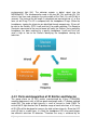
3.3.2 IR Triangulation
The tracking system is based on the infrared tracking system in [18]. It is
basically an IR emitter on the object. In the project, the group will use this emitter
to track a headset that will be used as a beacon for the chosen trackers or IR
collectors. The team needs to be able to track this beacon at different locations in
the room. The only issue is that there could be objects blocking the sight of path
from the beacon to the collector. To fix this problem the group thought about
using four different IR receivers which will be placed at the four corners of the
room. Each receiver will be mounted on its own motor which will let it rotate 90
degrees from one side of the corner wall to the other. Two receivers that follow
each other from left corner to right corner or vice-versa will be chosen. The
motors will then rotate to swipe the room until the IR transmitter is located. The
resulting distance will be calculated since the angle of rotation from the receivers
and the distance between them. Then this process will be repeated with the other
two receivers which then will give two more distances. The two distances will be
used to do the triangulation as described in the RF Triangulation section. The
distances are calculated as follows.
= (
cos( ! sin($ ! 1
− !
sin( + $ !
2
' = (
23 | P a g e
( ! sin($ !
!
sin( + $ !
Where is the distance between the 2 receivers and and $ are the angles
each receiver makes with the line connecting them. This (, '! coordinate is the
position of the transmitter given that the origin is at the center of two receivers
and the receivers are laying on the axis. So depending on which two receivers
that are used to map this (, '! coordinate to the virtual coordinate system of the
room. The overall idea is to track the IR beacon with two different sets of IR
collectors which will then team up to figure out a location of the original beacon.
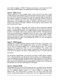
3.3.3 Camera vision Triangulation
A computer vision algorithm is going to be used to track each headset. There are
many different tracking algorithms used to track different objects depending on
their shape, color, and texture. These tracking algorithms require a lot of live data
to be able to be accurate so the group developed a positioning system to acquire
as much data as possible. The systems consist of using four different cameras in
each corner of the room. The cameras were positioned this way in case there is
interference between the moving objects in the room and the line of vision of
each camera and each headset. The issue in using all the data acquired from
each of the cameras is that it is computationally expensive; hence it will not be
able to do live tracking of each of the headphones inside the visual area. The
team will improve and fix this issue by using a system developed by Darryl Greig
from Hewlett Packard Labs. “Staggered sampling seeks to maximize the
sampling density across video frames, thus reducing the number of patches
sampled while retaining proportionally high recall rates.” This algorithm according
to Darryl Greig is able to “achieve around 90% of the recall of full (dense)
sampling while only evaluating the detector on around 10% of the image
locations. At the same time the precision of the detector increases.” [19] This
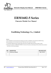
shows that the detector will only need to use 10% sampling data which will
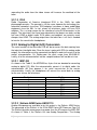
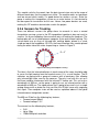
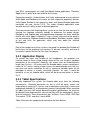
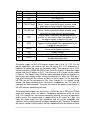
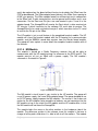
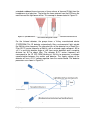
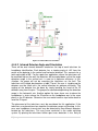
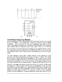
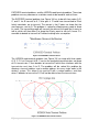
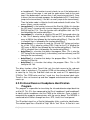
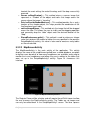
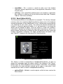
improve the computation delay by 90%. Figure 1 showcases this concept, in
which the blue triangles are each camera and the orange circle is the headset.
The dimensions of the room are subject to change since this are chosen by the
user; but for this system to work better the minimum width is 30ft and the
minimum length is 20ft.
24 | P a g e
Figure 1: Camera position in room for triangulation
A video is formed of a set of images, and in a set of colored images, each image
is formed of a 3D matrix RGB (Red, Green, Blue). Each pixel in the RGB matrix
ranges from 0 to 255. So the team can then find the color green by finding the
group of values in the 3D matrix as (0,255,0). Different combinations of these
values will give roughly 16,581,375 different shades of different colors. The
compilation of virtual points corresponding to each headset will be put together to
form one image containing all headsets. The image will have the pictorial position
of each of the headphones which can be used to find the (x,y) coordinates of
each of the headsets in a room.
3.3.3.1 Object tracking system
The system will consist of grabbing live data from each of the cameras and
applying the staggered sampling algorithm. The new sampled data will then be
input into a selection tracking algorithm. The idea is to select each headset in the
videos and then the selected object will be tracked even if it goes behind other
object and then re-appears. A probabilistic framework for off-line multiple object
tracking will be used to do so. “At each timestep, a small set of deterministic
candidates will be generated which is guaranteed to contain the correct solution.
Tracking an object within video then becomes possible using the Viterbi
algorithm…by defining a suitable candidate selection and a set transition
probabilities, tracking an object within the video becomes equivalent to finding
the most likely path in the candidate trellis using the Viterbi algorithm.” [20] Due
to this, the object tracking problem becomes a simpler mathematics problem that
25 | P a g e
can be solved rather quickly. The team will use MatLab at first to implement the
algorithm since this is a well know programming language use in computer vision
labs throughout the United States. After implementing the algorithm with sample
data obtained from the experiments, the team would then implement the
algorithm in the micro-controller chosen for the project.
3.3.3.2 Color tracking system
The system will consist of using the data given by the sampling algorithm
explained in section 3.1.3. The team will give each headset a bright color that is
not predominant in the environment. Since the color is not predominant in the
environment, a simple matrix subtraction can be done to find the position of the
object with the given color in the image. The team will first have to convert the
image from RGB (Red, Green, Blue) color to HSV(Hue Saturation Value) color.
The idea is to use the value part of the image which will then be mapped to the
one value that the color of the headphone has. To find a headphone whose color
will give off a bright red. This can represent a video as a set of images which
each image being represented as a 3d matrix RGB. The image is then converted
to a HSV color which. The color red is found in each image by tracking the values
of the V matrix to be 255, the H matrix to be 0, and the S matrix to also be 255.
This pixel position will be mapped to a virtual (x,y) coordinate system. The
position will be used as the position in the room that the headset is suited. The
downfall to this procedure is the mixture of colors. There are very similar colors in
a populated environment so this might get some noise data. This issue will then
be fixed by adding Hough features. The idea is to try to train the Hough features
with the shape of the LEDs which come from testing and sampling the test data.
This will add a threshold that will then act as a filter to take out all the noise data
input by other objects in the environment.
3.3.3.3 IR video tracking system (Hybrid)
The idea of Infra-red video tracking is to use a regular video camera with a filter
that will only collect infrared video feed. Each of the headsets will have an infrared emitter that will be used as a tag to show were a headset is located. The
camera will be able to capture the infra-red information and each headset will be
tracked by using a blob tacking computer vision algorithm. Since the headsets’
positions are not static it is assumed that there will be random objects blocking
the IR information from the IR cameras. This is going to be using multiple
cameras which will decrease the error of IR missed information.
The blob that is detected in the IR cameras is tracked by using the method in “A
Component-Labeling Algorithm Using Contour Tracing Technique” by Fu Chang
and Chun-Jen Chen. “The idea of this algorithm is to scan the image from left to
right and from top to bottom. When an unlabeled external contour point A is
encountered, we make a complete trace of the contour until we get back to A.
We also label A and all contour points with a new index.”[21] The idea is to track
a blob or a mass object which after applying the IR filtering to the camera will
26 | P a g e
give a white spot or area where the Infrared signal is the strongest. Then it will
track this area and by adding a threshold will be able to eliminate the noise
introduced by the environment. The reason for the filter is that human skin is very
good IR reflector so the IR light coming from the headsets and that then bounces
off of mirrors and human skin adds a great amount of noise to the camera. This
noise could be confused by an induced headphone which will then confuse the
user or even the program itself. This will cause the triangulation algorithm fail.
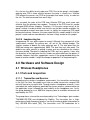
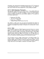
3.3.4 RF Triangulation
The group came up with two different ways to find the exact location of an object
inside a room by using radio frequency. The idea is to find each distance
between the transmitter and the four receivers placed at each corner of the room.
Once the distance is found, a virtual circle will be drawn using the receiver as the
center and the distance calculated as the radius. Another two virtual circles will
be drawn from two other receivers. The intersection area between the three
circles will be the approximately position of the headset. This will use four
receivers and three at time to get four different approximation areas. The
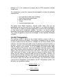
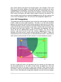
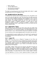
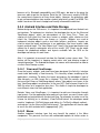
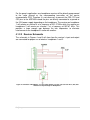
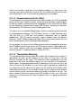
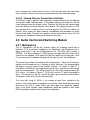
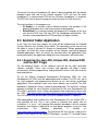
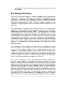
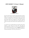
average of the four will be a more accurate position. [22] Figure 2 shows the
exact position of the transmitter given a measured distance from a transmitter to
each receiver and the location of each receiver in a virtual coordinate system.
Figure 2: Radio Frequency Triangulation Representation
A circle is made with each of the distances with the receiver as the center and
the measured distance as the radius. Three circles are picked at a time and
measure the center of the area in which they intersect. Since there are four
transmitters, there are four different combinations of three transmitters to choose
from at a time. After doing the triangulation algorithm on each of the four groups,
27 | P a g e
an average is taken of the x’s, y’s, and z’s. This is done to minimize the position
error. The average and the triangulation are calculated as shown below.
)$ = ( − !$ + (' − ' !$ + * $ ;
)$$ = ( − $ !$ + (' − '$ !$ + * $ ;
),$ = ( − , !$ + (' − ', !$ + * $ ;
-.ℎ/01/2
=
(' − ' !$ − (' − '$ !$ − $ + $$ + $ − $$
;
(2 − 2$ !
Then substitute back into the equation for the first sphere that produces the
equation for a circle, the solution to the intersection of the first two spheres,
' $ + * $ = )$ − $ ;
then substitute into the formula for the third sphere and solve for y; once y is
found then z can be found by using the first equation:
* = ±5)$ − ( − !$ − (' − ' !$;
The actual derivation of y becomes very long so a Matlab program was written
which returns x, y, z given D , D$ , D, , and their receivers corresponding
coordinates.
After (x,y,z)1, (x,y,z)2, (x,y,z)3, and (x,y,z)4 are found with the triangulation
function found above the average is solved for as follows:
(, ', *!9:; =
[(, ', *! + (, ', *!$ + (, ', *!, + (, ', *!= ]
4
3.3.4.1 Time of arrival (TOA or ToA) based analysis
Also called time of flight (ToF), is the travel time of a radio signal from a single
transmitter to a remote single receiver. This concept will be used by tagging a
message with the id of the headset. The absolute arrived time will be used to
calculate a distance since the rate in which the signal is traveling is known. Now
that the distances between the receivers and the transmitters are known so the
same triangulation system as the RSSI system for finding the average (x,y,z)
coordinates in which the transmitter is located can be used. The group is working
on a short range localization system so TOA tends to be very inaccurate so it
28 | P a g e
used a proposed two step TOA estimation provided by Shaohua Wu, Qinyu
Zhang, and Naitong Zhang from Harbin Institute of Technology. According to
their paper “A Two-step TOA Estimation Method for IR-UWB Ranging Systems.”
Time of Arrival can be estimated in a two-step process. “the first step, the block
that DP is within is detected from the low-rate energy samples of the received
signal, and this step is just for coarse estimation…the precise location of DP in
the detected block is obtained by MF based coherent algorithms…assuming that
nDP denotes the index of DP block…and change in DP is the delay offset of the
precise location of DP to the start point of that block.”[23] The TOA estimation is
represented as follows.
?̂ ABC = (DEF − 1!GH + IJEF
Where GH is the time of a block.
3.3.4.2 Received Signal Strength Indication (RSSI) analysis
system
RSSI is the amount of power present in a received radio signal. The higher the
RSSI number the stronger the signal. The idea is to use this value to map the
RSSI number with the distance between the receiver and the transmitter that
originated the signal. The group will be using four RF power meters to measure
this value at four different corners. A central tower knows the distances within
each receiver and the distances mapped from the RF power meters. The central
tower will use this information to calculate the exact position of the RF emitter
within the confinements of the four RF power meters.
The mapping of RF signal strength to the distance from the emitter will change
depending on the transmitter that was chosen. This mapping function will be
calculated from the calibration of the transmitter, so it can only estimate the real
distance value until the group experiments with the transmitter at hand.
The following will show the mapping of power to position, and the triangulation
functions.
KLLM = 10 log(!
= 10(QRRSTQRRSUVWXYZV[X\] !(T ^∝! + `9abHc9dbef
).gg0h0g./hi0/i − 0g2jg.ℎ0//0
This equation can estimate the distance from a signal, given that is the
distance between the transmitter and receiver, RSSI is the receiver signal
strength measurement, KLLM`9abHc9dbef is the RSSI offset, is the path loss
gradient of the environment, and `9abHc9dbef is the distance offset.[22]
Let V1, V2, V3, and V4 be the measured voltages corresponding to each
distance respectively.
29 | P a g e
) =
k
k$ k, k= ; )$ =
; ), =
; )= =
;
l
l
l
l
3.3.4.3 Summary
The team ended up choosing the RF triangulation system for the following
reasons. RF is able to travel through walls and objects so interference gets
minimized unlike IR and Video captures which are linearly vision based systems.
That lives us with choosing TOA and/or RSSI triangulation systems. The reason
why RSSI triangulation system was chosen is because TOA depends on an
algorithm to do estimation to the real TOA. Also because the team is working on
short range does not depend on time, since the rate of transmission of RF is
assume to be close to the speed of light in free air. This makes calculating the
distance from nanoseconds very inaccurate since the hardware latency is in the
microseconds hence it loses the nanosecond mark in the rounding result. Now
that the group has chosen a triangulation system, schematics and parts are
needed to build this system.
3.3.5 Transceivers
The sensing device will be an RF transceiver in the 2.4GHz frequency which will
be able to transmit the headphone label in which it is located. The triangulation
modules in each of the corners will be able to read this label and at the same
time they will read the RSSI analog value. So to recap, the specifications needed
for the RF device to use are that, it should have an analog RSSI output; it should
be able to transmit in different channels and addresses, the device should be
able to be used indoors, and its range should be higher than 40 feet.
The RF device chosen is the XBee S1 module that follows the 802.15.4 protocol.
This device is pretty handy since it brings a build in antenna and a programmable
micro-controller. The programmable micro-controller allows developers to change
the transceiver to receive and transmit in different channels and addresses
without having to change the circuit. The module is able to output the RSSI value
in analog form which is one of the desired specifications. The XBee module has
the following features main features,
•
•
•
•
•
•
•
•
Indoor transmission: 100’ (30 m)
Transmit Power: 1mW (0 dBm)
Receiver Sensitivity: -92 dBm
TX Peak Current: 45 mA (@3.3V)
RX Current: 50 mA (@3.3 V)
Power – down Curent: < 10 uA
RF Data Rate: 250,000 bps
Serial Interface Data Rate: 1200 bps-250 kbps
30 | P a g e
This module satisfies the needs from the data transmission rate to the range of
different baud rates that the project can utilize. The module works on low power
and low current which makes it a good device for wireless set-ups. Since the
group is making this triangulation system as an extra feature it is not desired to
be too expensive to maintain for the user. Hence, low power devices are used,
making this RF module a device to be used in the project.
3.3.6 Sensors for Tracking
There are different sensors the group chose to research in case a second
triangulation sensing system in the RF triangulation hypothesis does not result in
success. As discussed before there are other ways of tracking the headsets. The
backup plan will use a hybrid between computer vision and infrared tracking. This
set-up would use an array of Infrared light emitting diodes placed in a circle
shape on top of the headphone. IR LEDs are linear therefore they need to placed
facing the outer side of the circle shaped ring as shown in Figure 3.
D > 2”
Figure 3: IR led ring for headphone sensing
The idea is that the infrared collectors in each corner of the room should be able
to sense the light coming from the headsets even if it is a small fraction. The IR
collectors are going to be a group of cameras with a band pass filter allowing
only infrared light to be seen by the cameras. The only issue with this set up is
that there could be interference with the infrared TV locator unit. This unit uses a
wavelength of 950 nm, so the group is going to use an infrared emitter with a
wavelength of 850 nm. The video camera that is going to be used is just a simple
analog camera with a photo film that can filter the IR light hence only capturing
that signal. Then computer vision will be used as explained above in the hybrid
infrared camera triangulation section.
The 850 nm IR led has the following key features,
• Forward current 50mA
• Forward voltage 1.5 V
The camera has the following key features,
• 2.8V
• Up to 15fps
• 1200x1040 pixel resolution
31 | P a g e
•
•
•
•
Built-in color filter
1/3.3 inch optical format
Auto luminance control (ALC)
Auto white balance (AWB)
The hybrid sensing device comes out to be low budget which makes it a good
contingency plan for the RF triangulation system.
3.4 Graphical User Interface
A Graphical User Interface (GUI) will be designed for the sole benefit of the
users, in this case, the sports bar’s staff. The user will have the ability to monitor
the location of each headphone and observe each headphone’s status. Since the
users may not have a technical background, it is important to have an easy to
read interface. The platform hosting the GUI must have the ability to
communicate through a Bluetooth connection, to receive data on each
headphone’s location and status. Therefore this research is focused on what
devices and operating systems should support the GUI for an efficient and cost
effective implementation.
3.4.1 Application Types
When designing the user interface, the team had to take into account what
operating system (OS) the team would be most comfortable programming in and
its cost effectiveness. On a personal computer, Linux would prove to be rather
difficult to learn in such a short timeframe, along with the protocol in designing
the user interface and the required programming for the location and status data.
The group decided to research mobile devices that would host this interface the
best, looking between different operating systems such as: Apple iOS, Android,
and Blackberry.
3.4.1.1 Apple iOS
Apple’s operating system uses an Objective-C language for their iPads and
iPhones. It is a set of extensions to the C programming language, but based on
Smalltalk, which is one of the first object-oriented programming languages[24].
This language would be familiar to a programmer who knows the C/C++
programming language; however its style, structure, and techniques would take
too long to learn for the project.
Using Apple’s products would not be cost effective and would slow down the
design for two reasons. For people to be Apple developers, it is required to
purchase a developer license before they would have access to Apple’s Software
Development Kit (SDK). This license costs $99/year [25] and such a price would
hinder the budget. The group would also have to contact Apple’s Software
Licensing Department to set up a license agreement before the group could
32 | P a g e
distribute the application, due to using their intellectual property [26]. This would
use up valuable time meant for designing the project.
3.4.1.2 Android
Google developed a “software stack… that includes an operating system,
middleware, and key applications...[27]” for devices such as mobile phones and
tablets. This is known as Android and it is an open-source, Linux-based system
that allows developers the power to create applications and widgets with the only
limitation being the hardware device Android resides on.
The Java programming language is used to develop Android applications while
the SDK tools compile the code into an Android package (using a .apk suffix) to
allow installation and implementation on Android devices[28]. Google
recommends developers use an integrated development environment (IDE)
known as Eclipse, which uses the Android Development Tools (ADT) plugin to
“extend the capabilities of Eclipse to… quickly setup new Android projects, create
an application UI…[29]” This plugin allows developers to quickly and easily
design, debug and distribute applications. Alongside the Java source code, the
Android package requires a Manifest File that declares what components the
application requires to run and what minimum level of application programming
interface (API) the application needs to run on[30]. The manifest file is designed
in the XML programming language; a markup language used to transport and
store data[31], allowing data to be used virtually in any programming language,
so long as the data is stored appropriately once the xml file is read.
One of the advantages to developing in Android is the wide array of devices the
application can reside on. Many manufacturers use Android as their mobile
operating system (Toshiba, Asus, Motorola, etc.), which allows the team to
research into different devices that will fulfill the project requirements.
3.4.1.3 Blackberry
Blackberry uses a variety of languages to create applications for their devices.
The Blackberry Developer site offers potential developers with different language
SDKs, depending on how comfortable the language is to the developer and what
exactly they are designing.
The first development kit is the Native SDK in C/C++. This kit is limited to
development on the Blackberry Playbook (their version of a tablet). The SDK
opens up access to what the Playbook has to offer and gives developers a
detailed set of documentation to get started [32]. Not only does it allow the
developers to create simple applications, it also allows them to create high
definition 3D games and powerful applications that optimize the Playbook’s
processor.
33 | P a g e
Exclusive to Blackberry’s smartphones is the Java Software Development Kit.
Similar to the Native SDK, the Java SDK is packed with plenty of APIs that help
developers fully utilize their smartphone. Blackberry’s Java design, like Android,
also utilizes the powerful Eclipse IDE through a Java plug-in [33]. After the
group’s research, it was decided that since the smartphone and Playbook used
completely different languages to program, it would severely limit usability on
different platforms. Despite how powerful Blackberry’s Java SDK is, this distinct
difference may be a big deciding factor for the project.
Blackberry also offers HTML5 WebWorks; a package of web assets that do not
require a web server [34]. Not only are developers allowed to use HTML5 design
tools, they can also use the provided environment to code with CSS and
JavaScript; powerful web programming languages that design websites and
applications. HTML5 WebWorks runs on both Blackberry’s smartphones and
Playbook, so development can work on more than one platform. As powerful and
useful as this development kit is, the project does not require a web application to
process and display the headphone location and status data.
The only design challenge the group found noticeable was that Blackberry
requires all developers to sign their applications. Each signing is required
because of Blackberry’s Research In Motion (RIM) that “…track[s] the use of
some sensitive BlackBerry APIs for security and export control reasons”[35][36].
Signing the application also binds the developer’s identity to the application,
proving its authenticity and ownership. This may limit development time due to
waiting time on receiving debug tokens and key installation for applications. This
is not too major of a factor, but one worth considering.
As powerful as the Blackberry development kits are, research has shown that
Blackberry can translate Android applications into Blackberry applications;
allowing it to repackage Android applications for Blackberry devices [37]. This is
significant to the group’s decision because the repacking tools allow the group to
program in one language and convert to another. Though at this point in time
their conversion only allows Android’s Gingerbread operating system (v2.3.3)
applications to transfer over. It may be updated in the future to accommodate
Honeycomb (v3.0) and Ice Cream Sandwich (v4.0).
3.4.1.4 Selection
After considerable research, a comparison of these different operating systems
was used to decide which OS would be the most cost effective for the project.
The system has to be relatively simple to learn due to time constraints, fulfill
hardware requirements set out by the project, and be versatile in operational
devices it could work on.
Apple requires a developer license worth $99 so developers can access their
software development kits. Blackberry and Android both allow free access to
34 | P a g e
their SDKs, so developers can study them before making applications. Therefore,
Apple loses its ability to be cost effective for the team.
Comparing versatility, Android allows itself to be implemented on many devices
while Apple and Blackberry only works on their respective proprietary devices.
Unlike Apple, Blackberry has opened its doors and allowed Android application
translation (for now, version 2.3.3). This makes Android applications more
versatile due to its ability to work on different platforms.
The major concern with choosing which system to use was the time constraint in
learning the language efficiently enough to implement the project design.
Blackberry and Android both use programming languages the team would be
familiar with, while Apple’s Objective-C uses a syntax structure that the group is
not accustomed to. Between Android and Blackberry, Blackberry requires signing
to test and finish the application, which may slow down the interface
development.
Due to the comparison of these systems, the group has decided that Android will
be the focus for the graphical user interface. Its low cost, versatility, and ease of
use makes it perfect for the Eye Can Hear You project.
3.4.2 Application Display
To monitor the status and location of the headphones, the graphical user
interface needs to have a large enough layout for the user to view a top-down
perspective of the restaurant. Generally, the screen sizes for Android phones
range from 2 inches – 4.3 inches while the Android tablets screens range from 4
inches to 10.1 inches. Having a larger screen size would provide users with less
eye-strain and easier interaction as well as freeing up valuable space for the
developer to design a visually stimulating interface. As such, it would be
beneficial to use an Android tablet, which will be discussed further in section
3.4.3.
3.4.3 Tablet Specifications
To fully implement the system, the Android tablet must have the following
requirements: Bluetooth connection (as low as v2.0 will work), screen size
ranging from 4 inches to 10.1 inches, and an operating system that is current and
widespread (Android 3.2, or affectionately named, Honeycomb). When searching
for tablets that may fulfill and go beyond the project specifications, the team has
discovered three unique devices (not only do they fulfill the requirements, they’re
also cost effective). These three devices are: Toshiba’s Thrive, ASUS’s EEE Pad
Transformer TF101, and Acer’s Iconia A500.
Table 6 illustrates the compare and contrast of the three devices:
35 | P a g e
Specifications
Toshiba 10”
Thrive
10 inches
Bluetooth 3.0+HS
ASUS EEE Pad
TF101
10.1 inches
Bluetooth 2.1+EDR
Honeycomb (3.2)
Honeycomb (3.2)
Processor
NVIDIA Tegra 2
NVIDIA Tegra 2
Memory
1 GB DDR2 RAM
1GB DDR2 SDRAM
Retail Price
Internal
Storage
$379.99
$399.99
Acer Iconia
A500
10.1 inches
Bluetooth 2.1
Honeycomb
(3.2)
NVIDIA Tegra
2
1GB DDR2
RAM
$349.99
8 GB
16 GB
8 GB
Mini and Full-size
USB 2.0
~11 hours
USB ports with
optional keyboard
~16 hours
Micro and Fullsize USB 2.0
~7 hours
Screen Size
Bluetooth
Android
Version
USB Port
Battery Life
Table 6: Specifications pulled from manufacturer’s website: Toshiba[38], Asus[39], Acer[40]
During research, the team realized that it would be better to maximize the screen
to ten inches. Not only does this make the interface easier to read, the increased
size also allows the bigger tablet to sport more hardware to run more efficiently.
From Table 6, it is easy to see that these three tablets are very close in power to
each other. However, after extensive comparison, the team decided to choose
the Toshiba 10 inch Thrive.
The Thrive’s Bluetooth version is the highest of the three and is coupled with an
802.11 channel for extra wireless communication. In other words, if the Bluetooth
device begins to slow down because of too much traffic, this “high speed”
channel will use a 802.11 connection to transfer data faster[41]. This protocol
gives the project freedom to rely on fast connection speeds between the
microcontrollers and the tablet, which will allow the team to check the location of
each headphone quickly and in real-time.
Another specification that the team found to be useful is the Universal Serial Bus
ports these devices come with. At this point in the project, the group decided it is
not a high priority, but would be wise to be prepared for any design surprises. If
at any point the design requires the tablet to communicate with the
microcontrollers through a USB connection, it is better for the tablet to have the
fastest connection possible. The ASUS Transformer is not helpful in this regard,
since it requires the use of an optional keyboard (sold separately) to connect
through USB. At this point, the design plan is to have the tablet be mobile, so it
would be beneficial for the group to use Bluetooth instead of USB.
Beyond the Bluetooth and USB specifications, these devices are fairly equal
(except for the battery life and internal storage). The Thrive was chosen, not just
36 | P a g e
because of its Bluetooth compatibility and USB ports, but due to the price the
team was able to get for the device. Retail for the Thrive costs roughly $379.99,
the second most expensive of these three tablets. However, the group was able
to get a discounted price from another student (who briefly used it) for $250. This
made it easier on the team’s budget and heavily influenced the decision.
3.4.4 Android Interface and Data Storage
Before design on the GUI occurs, it is important to understand how Android sets
up interfaces. To implement an interface, the developer has to use the View and
ViewGroup objects, which are descendants of the View Class. There are
subclasses that inherit the View class known as widgets, while subclasses that
inherit the ViewGroup class are known as Layouts. Widgets are used to
implement interface objects such as text fields, buttons, and forms. Layouts are
used to setup the layout architecture in an application, like linear layouts, table
layouts and grid views. The View Object itself “store[s] the layout parameters and
content for a specific rectangular area of the screen. [42]” Views can be made
through the predefined widgets and layouts available with the SDK or the
developer can design his own views.
Also, it is important to research into how the Android system stores data. This
feature will be important in keeping certain data safe and allowing usage of
stored information. The Android developer site comes with information on how to
use their Data Storage system.
3.4.4.1 Views and ViewGroups
Once the layouts, widgets, and views have been designed, the Activity’s interface
needs to be defined by a View hierarchy. This hierarchy allows rendering of the
application’s interface. To define the layout and express the developer’s type of
view hierarchy, an XML layout file is required. This XML file contains elements
that are either Views or ViewGroup objects where “View objects are leaves in the
tree, ViewGroup objects are branches in the tree [42]”. Each element listed in this
XML file refers to its respective Java class. This makes it simple for developers to
nest different views into their application.
Besides Views and ViewGroups, it is important to add user interaction through
input events. For the application to be aware of user input, an event listener must
be defined and registered with the desired View. For example, to make use of the
listener for clicking (as in a button), View.OnClickListener, the developer would
need to “implement OnClickListener and define its OnClick() callback method…
and register it to the View setOnClickListener().” The application will then be able
to sense the click and deal with it appropriately. [42]
3.4.4.2 Menus
Another important interface type that may benefit the project is the Menu
component. This presents the user with comfortable options to further action in
37 | P a g e
the application. Some important Menu types are: Options Menu, Context Menu,
and the Popup Menu. The Options menu is where important, global actions are
placed (Search, Settings, Exit, etc.). The Context Menu appears when users
press down on the screen (or click) for an extended period; providing specific
actions that “affect the selected content or context frame.” Finally, the Popup
Menu is used to “display a list of items in a vertical list…good for providing an
overflow of actions that relate to specific content.” Each Menu type is important to
use and will help the project provide a nice, seamless interface for the user.[43]
3.4.4.3 Data Storage
The Android system comes prepared with different options on storing data,
whether it is the application or information the application utilizes. These options
are: Shared Preferences, Internal Storage, External Storage, SQLite Databases,
and a Network Connection. However, for the project, the team will be
implementing a SQLite Database for storing headphone and customer
information.
The SQLite Database is useful for developers because it allows them to store
structured data that would be difficult in any other format. Using the SQL
language and protocols, developers can create relationships and entities to help
query specific data, so the application can repeatedly and accurately use the
stored information.
3.4.5 Bluetooth Connection
For the Android Tablet to connect to the master microcontroller, a Bluetooth
connection was preferred; allowing the team to have a fast, dedicated transfer of
data. Android’s development kit comes with Bluetooth APIs, so developers may
use the wireless point-to-point features [47]. The Bluetooth API allows
applications to “scan for other Bluetooth devices, query…for paired Bluetooth
devices…Transfer data to and from other devices, [and] manage multiple
connections.[47]” The Android Developer website provides the team with general
instructions on how to setup Bluetooth, finding available or paired devices,
connecting them to the tablet device and communicating between the tablet and
Bluetooth chip in the master microcontroller. However, setting up Bluetooth, the
XML Manifest file must contain two major Bluetooth permissions (BLUETOOTH
and BLUETOOTH_ADMIN); admin permission being used for discovery and
manipulation of settings and regular Bluetooth permission being used for
requesting and accepting connections and transferring data.[47]
In general, a Bluetooth connection is established when two devices, either being
a server or a client, focused on communicating with each other both have “a
connected BlueToothSocket on the same RFCOMM channel.[48]” Android offers
the application the ability to either act as a server to connect to a client device (or
server device, if both are servers then they will each listen for connections) or act
as a client connecting to a server device. Depending on which way the team
38 | P a g e
decides to go with, the developer site has given very detailed instructions on how
to accomplish both choices.
The Bluetooth module the team have been interested in, the Module Bluetooth
2.0/EDR Class1, by default does not require an authentication code for pairing
between itself and the corresponding device. However, if a device connecting to
it requires authentication, then it will go through a pairing process.[49] For the
project, the module will be programmed and used on the master microcontroller,
utilizing the default setting where there will be no authentication between
devices. The reason this method was chosen was because the module is being
set up to act as the server and the tablet will act as a client connecting to the
module. Because the microcontroller will not have its own interface, the Bluetooth
module would need to be programmed to store a static security pin code;
preventing a random string to be generated and having trouble with the tablet
connecting to it.[49]
The module allows up to 8 first-in, first-out pairings, giving multiple tablets the
ability to connect to the microcontroller; more of the staff could use the
application.[49] Connecting to the module will require the tablet application to
enter in a secure code which has already been statically set in the Bluetooth
module. To make this pairing and connection seamless, a hard-coded password
may be put behind the scenes that will make the secure connection without the
user having to manually connect.
Setting up the Bluetooth module as a Server and the Android tablet as the Client
with the settings the team has researched will allow quick and easy connections.
Designing this connection will be explained later in this group paper.
3.5 Microprocessors
The “Eye Can Hear You” project will not be developing its own data processing
device. Hence the team is going to choose a microprocessor that can do this
from the available ones in the market. The group is going to give a brief
explanation of each of the micro-processing devices that are being considered
for the main device in the project. The team is considering using the MSP430,
Atmega Series, PIC, and the Stellaris arm processor. The group decided to
choose these four microprocessors because the project team members have at
some point worked with one of these microprocessor families. The
microprocessor desired to be used in the project should have low power
consumption, high CPU speed, high flash memory, as much RAM as possible,
more than 10 analog pins, more than 10 digital pins, at least two serial IO ports,
an internal clock, low programming difficulty, and low debugging difficulty.
39 | P a g e
3.5.1 MSP430
The MSP430 microcontrollers are “16-bit, RISC-based, mixed-signal processors
designed specifically for ultra-low-power.”[31] This is good in the sense that the
microcontroller can be used without having to be plugged into a wall. The
microcontroller has the following key features,
•
•
•
•
•
8-MHz to 25-MHz CPU Speed
0.5KB to 256KB Flash
128B to 18KB RAM
14 to 113; 25+ packages
Internal 25 MHz clock
The MSP430 development environment uses the MSP-Exp430G2 development
launch pad board that supports development on al MSP430 devices. TI’s Code
Composer Studio IDE, IAR Embedded Workbench or the open-source MSPGCC
can be used as software development tools to program the microcontroller.[31]
3.5.2 Atmega Series
The Atmega Series is a “low-power CMOS 8-bit microcontroller based on the
AVR enhanced RISC architecture.”[44] The group chose the atmega328 since
this is the one that the project team is more familiar with in the Atmega Series.
The atmega328 has the following key features,
•
•
•
•
•
•
32KB Flash
1KB EEPROM
2KB RAM
14 Digital, and 6 Analog pins
1 Serial IO hardware serial (Software Serial Available)
Internal 8MHz clock
The Atmega Series uses the Arduino IDE and development board to program
and debug the microcontroller. The microcontroller is boot loaded to be able to
be used with the Arduino UNO board which makes it easy to use and makes the
Arduino open source libraries available for use. The Atmega328 is programmed
by using the Arduino IDE but is able to use external C/ C++ files which make
programming with it more common.
3.5.3 PIC micro-controller
The PIC microcontroller “offers…high computational performance at an
economical price-with addition of high-endurance.”[51] This is good since the
group is trying to find the best possible microcontroller that can handle all of the
computations while keeping a low price close to or lower to than the budget. The
micro-controller from the PIC family that was decided upon was the PIC18F2525.
The reason is that from all the PICs it seems that this is the one that kept closer
40 | P a g e
to the micro-controller standards. The PIC18F2525 has the following key
features:
•
•
•
•
•
4 MHz external clock
Up to 13 Channel Analog-to-Digital Converter
48 Kbytes flash memory
3968 bytes SRAM data memory
1024 bytes EEPROM data memory
The PIC18F2525 can be easily programmed with different development boards
found online. The team decided that it would be easier to just make a personal
development board that basically connects the desired pins from the datasheet to
a USB that will let the data from the computer into the micro-controller. The
micro-controller can be programmed by using MPLab IDE which is uses a
language close to assembly.
3.5.4 Stellaris Cortex-M3
The Stellaris based controllers “brings high-performance 32-bit computing to
cost-sensitive embedded microcontroller applications.”[50] This works great for
the project since the lower the cost the more features that can be added to end
project. This microcontroller is also effective since it was made “for applications
requiring extreme conservation of power.”[50] The application is going to run on
low power hence making it cheaper for the user to maintain. The Stellaris chosen
to be used is the LM3S1110 which has the following key features,
•
•
•
•
•
32 Bit RISC Performance
25 MHz operation
64 KB single cycle flash
16 KB single cycle SRAM
Programmable internal clock
The Stellaris microcontrollers are programmed by using the Stellaris LM3S1968
evaluation board. This board allows the team to connect the microcontroller to
the PC which then is programmed by using ccsv5 which is plug-in for the eclipse
open source development software. This software uses C as the development
language.
3.5.5 Summary
The “Eye Can Hear You” project has different modules that require different
types of processing power. For this reason the team has decided to use more
than one type of micro-controller for the project. The team is going to use the
Stellaris micro-processor for the main board. The reason is that the data
acquisition and processing of the board provides a heavy work load for any
micro-controller. Hence, after looking at the characteristics of the four families the
41 | P a g e
team decided to use the Stellaris micro-processor. The Stellaris micro-processor
can be sampled from <www.ti.com> which makes this a convenient microcontroller for low budget projects. The headphones will also be using two
different microcontrollers, the msp430g2231 and the atmega328. The msp430 is
used for Pulse Width Modulation (PWM) out into the infrared LEDs. The
atmega328 is used for the triangulation since it has a bigger amount of flash
memory than the msp430g2231 which is convenient for the triangulation
algorithm. After reading on the micro-controller it looks like it should be able to
handle the constant data processing. These two micro-controllers were also used
for the headphones since they are very low in price which is adequate for the
project.
3.6 Printed Circuit Board
The master board will be a printed circuit board (PCB). The PCB will do the
calculations for the triangulation and will reroute the sound for the headphones.
The PCB was chosen for the master microcontroller because it comes in various
sizes. The team is ordering a large printed circuit board because it is more
appropriate for this project. The large size of the PCB allows access to more
parts for the master microcontroller. Most of the parts that the team is ordering
are surface mounted. Therefore, they have to be populated by a PCB company.
3.6.1 Parts and Acquisition
The microcontrollers that the team is looking at are in section 3.5. Although most
can be sampled, there is a limited amount of samples that can be acquired for
free. The costs of the microcontrollers are listed in the chart below. The prices
were found at DigiKey.com.
3.6.1.1 Microcontroller
The microcontrollers that are being looked at are in section 3.5. Although most
can be sampled, there are only limited amounts that can be sampled. The costs
of the microcontrollers are listed in Table 7. The prices were found at
DigiKey.com.
Part
Part Number
Price (Dollars)
MSP430
MSP430F1471IPM
9.42
Atmel Atmega328
ATMEGA328-AU
2.77
Stellaris Cortex M3
LM3S1110-IBZ25-A2
6.88
Table 7: List of Different Microcontrollers Available
42 | P a g e
3.6.1.2 Bluetooth Module
A Bluetooth module will be used to communicate between the master
microcontroller and the GUI. Several possible modules have been found and are
listed in Table 8. The prices were found at DigiKey.com.
Part
Part Number
Price (Dollars)
MOD BLUETOOTH
V2.0+EDR SPP EXT
F2M03GX-S01
49.93
MODULE BLUETOOTH
2.0/EDR CLASS1
RN-21
29.84
Table 8: List of Different Bluetooth Modules
3.6.1.3 Radio Frequency Module
The group has been looking at several RF modules for the board. The sound
after being processed by the MUXs will be sent via the RF module to the
headphones. A large factor in selecting the RF module is the frequency range.
The group has to make sure that it is wide enough to operate multiple
headphones. For each of the modules researched, that range is sizably large.
Another factor that has to be dealt with is the difference between surface
mounted and through hole. Since the master board is going to be a PCB most
parts will be surface mounted. However, in the TXM-900-HP3-PPS is actually
through hole. The reason that this is being considered is because it is a pair with
a receiver. The board on the headphones will have a solder less breadboard and
therefore need through hole parts. Another factor is range. With a ¼ or ½ wave
$,=
antenna, the range for the TXM-900-HP3-PPS will be = Bmnc9dbf;ocnpqnf`r. The
SA58646BD, 118 was found at avnetexpress.avnet.com. The TXM-900-HP3PPS was found at Digikey.com. Table 9 lists these different modules.
Part
IC TXRX 900MHZ 64LQFP
Linx High-Performance
RF Module
Part Number
SA58646BD,118
Price (Dollars)
3.93
TXM-900-HP3-PPS
24.10
Table 9: List of Different Radio Frequency Modules
3.6.1.4 Radio Frequency Antenna
The antenna for the module has many factors to choose from. One of the main
factors is its frequency range. If it cannot meet the frequency range requirements
of the module, then it is useless to this project. Another factor to consider is
impedance. If the impedance does not match that of the module antenna output,
it could damage the antenna or the module. Table 10 lists these different RF
antennas.
43 | P a g e
Part
Antenna Factor 900 MHz
ANTENNA HELICAL ISM
900MHZ SMD
Part Number
ANT-916_CW-QW
W3112A
Price (Dollars)
5.75
1.93
Table 10: List of Different RF Antennas
3.6.1.5 Multiplexer
The MUX on the master board will handle the sound switching. When the IR
receiver reports to the microcontroller, the microcontroller will then output a one
or a zero to the control lines. Depending on the control lines value, it will
determine which television the headphone will listen to. The following MUXs in
Table 11 were found at Digikey.com.
Part
IC MULTIPLEXER 4X1
10MSOP
IC MUX 4:1 LVPECL
PREC LP 32-MLF
Part Number
ADG704BRMZ
Price (Dollars)
2.84
SY89855UMG
6.43
Table 11: List of Different Multiplexers
3.6.1.6 RCA Connector
The group will use an RCA connector that will take the data from the
triangulations to the microcontroller. The RCA connector will also take in
sound from the televisions. The RCA connector that is going to be used is
CONN RCA JACK METAL RCJ-012. On Digikey.com, it is listed as $0.96
connector. Four will be needed to connect with the RF triangulation.
additional six will be used for RCA connectors for the sound input from
televisions.
RF
the
the
per
An
the
3.6.2 Vendor and Assembly
Choosing the right PCB vendor is critical for the project’s success. There are
many vendors to choose from. Therefore, research for this section was lengthy
and detailed. The group decided to set criteria for choosing the PCB vendor for
the project. Because this project requires particular specifications, a set of criteria
were developed that designated if each vendor offered the specifications needed
for the master microcontroller.
In addition to offering the specifications needed for this project, it was determined
that price and turnaround time needed to be considered as part of the criteria.
Because the project is set on a limited budget, it was needed to ensure that the
vendor offers PCBs within the designated price range. The maximum amount of
money allotted for the PCB is $300. However, the group set a goal to find a PCB
that is well under the maximum allotted price range. By setting a specific
maximum price range, the group was able to quickly eliminate vendors that do
not meet those criteria.
44 | P a g e
The turnaround time was also an important aspect that needs to be considered
during the research. Since the project is on a strict schedule, it is vital that a
vendor is found that has a quick turnaround time. Finding a vendor that has a
fast turnaround will allow the team to build this part of the project as early as
possible. The PCB is the foundation for the project; therefore, it is important that
the team begins working with it so that issues that could arise can be found
earlier. Without the PCB, the project would not succeed. This is why finding the
right vendor is so important.
The group also had to keep in mind that the project requires a particular size
PCB. The specifications that the team looked for are 12 square inches and 4
layers. By setting a PCB size for this project, it decreased any chance of
miscommunication regarding the ordering of this part. Setting the size also allows
the team to make sure that it fits the other design elements of the project. When
searching for PCB vendors, the team is often able to receive quotes for the price.
Since the group already knows the size of the PCB needed, it is easy to select a
size for the quote. Therefore, the exact price is known for the PCB from the
specific vendor.
The team was relatively unfamiliar with the PCB vendors available. In order to
find the best vendor for the needs, the team decided that it would be beneficial to
research five different vendors. Using developed criteria, the team was able to
narrow down the pros and cons of each vendor, as well as any additional
companies needed to contact, such as for assembly.
3.6.2.1 ExpressPCB
ExpressPCB offers several very convenient services. Their website is easy to
navigate and their quote system is very standardized. They offer several different
packages. These packages include standard, miniboard, production, protopro, 4
layer productions, and 4 layer protopro. The option considered is the 4 layer
production. This package allows the group to capture the 4 layers needed for the
project’s PCB. The 4 layer production allows a more compact design, as well as
eases the amount of work involved for layout. Express PCB also assembles the
PCB, making it less work on the design end as far as contacting a company that
assembles PCB’s. They also offer the PCB size that the group is looking for. The
total lead time for Express PCB was 10 days.
The formula they use for the pricing of the PCB is quite simple. They use for the
10 day option, $273 + (.68 * Number of boards * Board area in square inches) +
(.5 * Number of boards) – Quantity Discount + Shipping. Unfortunately, Express
PCF requires an order of at least 2 PCBs. Although the group would be paying
for an additional PCB, it is recognized that it could be useful to the team in case
one board happens to break. According to their online quote system, the total
45 | P a g e
cost without shipping, is $290.32. Because the pricing is at the high end of the
price range without shipping, the group decided to explore other options.
3.6.2.2 PCB 4 Less
Pcb4less.com has a very complex quote system and will only allow a bulk
number of PCBs to be ordered. A convenient feature that they offer is the option
to test the PCB. By testing the PCB first, the team would be able to determine if
the company correctly assembled the PCB as requested, without having the
team test it. Pcb4less.com tests each PCB before shipping to verify that all
specifications are included and functional. Pcb4less.com also offers all of the
services that Express PCB does; however the pricing was quite different. The
total lead time was 5 days.
PCB 4 Less charges a very large tool charge on top of their bulk ordering
system. The tool charge is $200. The average price for the PCB itself from this
vendor is around $50. However, this vendor requires a much larger quantity for
purchase. The vendor requires that customers order 25 PCBs. The large quantity
necessary for ordering was completely out of the team’s price range, and was
also inefficient for the project. There is no use for such a large amount of PCBs,
and the team does not have the monetary funds to buy them from this vendor.
After determining this aspect, it was decided that PCB 4 Less was no longer an
option for the PCB vendor.
3.6.2.3 PCB Express
PCBExpress is another excellent website to order PCBs from. This vendor is not
affiliated with Express PCB, although their names are similar. PCBExpress also
has an easy to navigate website with a simple quoting system. This vendor
requires that at least two PCBs at a time are ordered. This vendor also
assembles the PCB like the other vendors researched. They offer the correct
PCB size for the project, and have a simple ordering system. The total lead time
was 3 days.
For the group’s specifications, the total cost will come to $497 without shipping.
This is fairly reasonable, considering the amount of parts on the board; however,
it also considerably exceeds the group’s price range. Because of PCB Express’
high cost, the group decided that this was not a valid option for this project. The
price exceeds the allotted amount by almost $200, an amount that is too high for
the group to even consider expanding the PCB budget.
3.6.2.4 Ultimate PCB
Ultimatepcb.com was the last PCB vendor that was researched. Since the other
vendors researched did not fit all of the criteria, this vendor was chosen. This site
has an excellent quoting system. It is much simpler to navigate than
pcb4less.com. They allow buyers to choose the silk screen color and have
several customization options to choose from. The most appealing thing about
46 | P a g e
this site was the ability to only order one PCB. Due to the group’s strict budget,
ordering one PCB is more realistic because the price is usually less. Ultimate
PCB offered the correct size PCB for the project and made it easy to select on
the site. The total turnaround time was 5 days.
It is assumed, the price of the PCB from Ultimate PCB was much more cost
effective than the previous four vendors. The price of the PCB from this vendor
averaged $230 without shipping. Therefore, it fit the price range and all of the
group’s criteria. In order to make sure that this was the best vendor available, the
team wanted to research one more to see if a slightly less expensive PCB could
be found elsewhere. However, the team noted that this vendor would fit all of the
project’s needs and was considered as the team’s likely vendor for this project.
3.6.2.5 Imagineering Inc.
Imagineering Inc. was quite expensive overall. Although they covered all of the
specifications needed, the pricing was still out of the allotted budget. The
smallest number of boards the team could get was 5. The total price after the
$200 tool charge was approximately $635. The lead time was one week. The
website was quite specific in getting a quote and very detailed on the choices
that were picked. The detail in ordering the PCBs was very specific. It was after
the discovery of the high price that this vendor was eliminated from the options. If
need be, however, they offer a population service. If the group decided to buy the
board at another vendor, it might be cheaper to populate it at Imagineering Inc.
4.0 Hardware and Software Design
4.1 Wireless Headphones
4.1.1 Parts and Acquisition
4.1.1.1 Transmitter and Receiver
According to the wireless headphone requirements, the transmitter and receiver
in the Eye Can Hear You project must have an audio transmission range of 100
feet with low noise to signal ratio. Through wireless headphone research, it was
concluded that radio frequency would be the chosen wireless communication for
the application since it allowed the most mobility to the headphone user. Lastly,
the group decided to use a 900 MHz frequency due to available unlicensed use
regulated by the FCC.
The group chose a transmitter manufactured by Linx Technologies (part number:
TXM-900-HP3-PP0) and distributed by DigiKey. The transmitter has a “highperformance [radio frequency] wireless transfer of analog or digital information [in
the]…902-928 MHz band” [53]. The transmitter uses FM modulation for a
47 | P a g e
“reliable performance” [53]. This transmitter has an audio transmission range of
1000 feet when paired with an HP3 receiver which is more than enough for the
application. This transmitter is cost efficient since no other parts are necessary
for signal processing and transmission other than an antenna. This part also
meets the groups requirements of a through hole device which can be soldered
to the board instead of propagated by a company. The datasheet for the HP3
transmitter was detailed and thoroughly explained, confirming the group’s
decision to use the HP3 transmitter [53].
To ensure the compatibility of the transmitter with the receiver, the group decided
to choose the HP3 receiver manufactured by the same company Linx
Technologies (part number: RXM-900-HP3-PP0) and also distributed by DigiKey.
The HP3 receiver has the same specifications as the HP3 transmitter except for
the operation of using FM demodulation. This receiver has a low noise to signal
ratio produced as well.
4.1.1.2 Potentiometer
To ensure one knob controlled the volume for both the right and left speaker, the
group chose a dual-gang potentiometer of 10 kΩ to use in the audio amplifier
circuit of Figure 6. Since the application of the potentiometer was for audio
volume control, the group specifically chose an audio taper dual-gang
potentiometer over a linear taper potentiometer due to its logarithmic tapering
operation that how humans discern volume [65]. The potentiometer (part number:
230-100-A-10K) will be purchased from Mammoth Electronics.
4.1.1.3 Operational Amplifier
The operational amplifiers used in Figure 6 will be ordered through Digikey (part
number: TL082CP/NOPB) as a through hole device consisting of two JFET
packaged operational amplifiers. The device will be purchased at $1.42 apiece.
4.1.2 Receiver Module
The HP3 receiver module located on the headphone will receive the FM radio
waves broadcasted by the paired HP3 transmitter and demodulate it for user
audio. For this particular receiver the quarter wave length antenna will retrieve
the radio frequency signal which will be filtered, amplified, demodulated and
outputted through an analog signal. The microcontroller within the module
reduces the need of extensive programming and external components. It reads in
the three select lines and automatically programs the synthesizer [62] to convert
the electrical impulses into sound.
4.1.2.1 Pin Layout and Functionality
The receiver module has a total of eighteen pins used to select channels, enable,
and output sound. In Table 12, the related pin number, pin name and description
is briefly outlined.
48 | P a g e
Pin #
1
2-8
9
10
Name
ANT
GND
NC
CS0
11
CS1/SS Clock
12
CS2/SS Data
13
PDN
14
RSSI
15
MODE
16
17
Vcc
AUDIO
18
DATA
Description
50-ohm RF Input
Analog Ground
No Connection
Channel Select 0
Channel Select 1/Serial Select Clock. Channel
Select 1 when in parallel channel selection mode,
clock input for serial channel selection mode.
Channel Select 2/ Serial Select Data. Channel
Select 2 when in parallel channel selection mode,
data input for serial channel selection mode.
Power Down. Pulling this line low will place the
receiver in a low-current state. The module will not
be able to receive a signal in this state.
Received Signal Strength Indicator. This line will
supply an analog voltage that is proportional to the
strength of received signal.
Mode Select. GND for parallel channel selection,
Vcc for serial channel selection.
Supply Voltage
Recovered Analog Output
Digital Data Output. This line will output the
demodulated digital data.
Table 12: Pin description provided by Linx Technologies in RXM-900-HP3-PP0 datasheet.
The power supply for the HP3 receiver ranges from 2.8 to 13 V DC. For the
project application, the receiver will use the typical 3.3 V DC followed by a
capacitor to reduce the noise on the power supply. The group will use a 3.3 V
voltage regulator (LP2950-33LPRE3) from Texas Instruments to drop the supply
voltage from the 9V battery to 3.3V. The schematic of this layout can be viewed
in Figure 4. The Power Down (PDN) pin when grounded will put the receiver in a
low current consumption mode, turning the receiver off. When the PDN pin is
high or left floating will the receiver will be in an active mode. For the application
the PDN pin will be connected to Vcc. Even though this is a power saving
feature, the group decided when the wireless headphones are ON, they will
constantly be receiving audio. Therefore the usage of the power saving feature of
the HP3 receiver would barely be used.
The analog audio output from the receiver’s AUDIO pin has a 50 KHz to 28 KHz
range that closely meets the wireless headphone requirement of 20 Hz to 20
KHz. This receiver has an excellent frequency band for the user to experience
quality sound. The analog output is composed of an AC signal of 1 Vpp. Linx
notes the audio output has high impedance and will not be compatible with
speakers which normally operate on lower impedance [62]. Therefore, the project
will require a buffer circuit to adjust the high impedance from the receiver to lower
49 | P a g e
impedance for speaker applications. The schematic of the operational amplifier
connection can be viewed in Figure 6.
The audio for the headphones will be received through the quarter wave antenna
connected to the RP-SMA female connector (CONREVSMA001). The center
antenna connector pin will be directly traced to the ANT pin of the RF receiver for
receiving sound from the transmitter.
The sound from the receiver’s AUDIO pin is connected to the audio buffer
amplifier circuit. During implementation, noise occurred when the DATA line was
left floating. It was suggested by Linx Technologies Senior RF Engineer to
connect the DATA pin to Vcc. This drastically eliminated noise from the circuit.
4.1.2.2 Channel Selection
The HP3 allows the user a parallel selection mode to choose a channel for the
transmitter and receiver to broadcast over. Each channel broadcasts over a
particular frequency. For parallel selection there are 8 channels that may be
selected using the CS0, CS1 and CS2 pins. Table 13 shows the select line
values corresponding the channel and frequency.
CS2
CS1
CS0
Channel
0
0
0
0
1
1
1
1
0
0
1
1
0
0
1
1
0
1
0
1
0
1
0
1
0
1
2
3
4
5
6
7
Frequency
(MHz)
903.37
906.37
907.87
909.37
912.37
915.37
919.87
921.37
Table 13: Parallel selection table provided by the manufacture Linx in the RXM-900-HP3-PP0
datsheet.
If more than eight channels are need to carry out the functionality of a project,
Linx Technology has another RF module (RXM-900-HP3-PPS) that includes the
serial selection can be used which provides the user with 100 channels. The
serial selection is implemented through using CS1 and CS2 as serial ports. CS1
becomes the clock line and CS2 becomes the data line [62]. These lines are
programmed to send a binary value from 0 to 100 through the serial mode
defined in the datasheet. For the serial selection, timing must be considered
when sending the serial channel adding to the complexity of programming. Since
the project currently implements two headphones receiving audio from 2 different
transmitters on the master microcontroller board, the group decided that the
RXM-900-HP3-PP0 module would best meet the project requirement since only
parallel selection is needed.
50 | P a g e
For the group’s application, one headphone receiver will be directly programmed
to the same channel as the corresponding transmitter on the master
microcontroller PCB. Therefore it is not necessary to connect the CS0, CS1 and
CS2 pins to the MSP430 instead the pins are directly connected to a ground or
the 3.3V power supply depending on the headphone. The receiver on headphone
1 will receive on channel 8 at a frequency of 921.37 MHz while the receiver on
headphone 2 will receive on channel 1 at a frequency of 907.87 MHz. This
provides a large enough gap between the two frequencies to eliminate
interference of one headphone’s audio with another.
4.1.2.3 Receiver Schematic
The schematic in Figures 4 and 5 will show how the receiver’s input and output
are connected for proper use of wireless headphone 1 and 2.
Figure 4: Schematic of Headphone 1 receiver with channel selection. The selection lines, CS0, CS1
and CS2 are all pulled high for Headphone 1.
51 | P a g e
Figure 5: Schematic of Headphone 2 receiver with channel selection. The selection lines CS0, CS1
and CS2 are all pulled low for Headphone 2. Note A: Refer to Figure 7 for the schematic relating to
AUDIO output pin.
4.1.3 Speakers
4.1.3.1 Audio Buffer Amplifier Schematic and Operation
The analog output of the receiver has high impedance in comparison to the
speakers that have low impedance. Therefore a common solution is to use an
operational amplifier as a buffer between the two devices. The circuit diagram in
Figure 6 was implemented to amplify the signal and reduce noise between the
receiver and the speakers.
52 | P a g e
Figure 6: Schematic of the audio control, buffering and noise reduction from the receiver to the
nd
speakers using a dual gang audio taper potentiometer, buffer circuit and modified 2 order BPF
respectively.
The AUDIO output (pin 17) from the HP3 receiver will have a 1 volt peak to peak
AC output into the labeled AudioIn pin on the Figure 6 schematic. The audio will
be split into the top and bottom of the potentiometer, one for each speaker. The
potentiometer will be used for volume control. The output of the potentiometer
will be connected to a capacitor to filter noise before inputted into a basic
operational amplifier (TL082) manufactured by Texas instruments. The
operational amplifiers are limited by the Vcc and Vdd power supply. Since the
audio signal is a 1 Vpp, the design uses +4.5 and -4.5 as the Vcc and Vdd
respectively. This is implemented by creating a voltage divider circuit from a 9V
battery. The operation amplifier is a buffer to reduce the high impedance of the
receiver to the low impedance of the speakers. This is followed by a modified 2nd
order band pass filter (BPF) to block out noise before entering the speakers of
the headphone. The cutoff frequencies for the BPF are 50Hz and 28KHz. The
speakers used in Figure 6 are the speakers included in the casing of the
headphones. The wires of the headphones are split and connected to the circuit.
4.1.3.2 Volume Control
The potentiometer is a voltage divider that changes the voltage input to the
operational amplifier essentially changing the volume of the speaker. In Figure 6
53 | P a g e
there are two potentiometers, one for each speaker. However having two volume
controls is uncommon in headphones. To implement volume control to both
speakers using one device, the group decided to use a dual gang potentiometer
[65]. By using a dual gang potentiometer the group is able to operate the left and
right speaker circuits with one knob.
The potentiometer has 6 lags where the top and bottom lags represent separate
potentiometers driven by the same shaft. Vcc must be connected to the left lags
and the ground will be connected to the right lags. The center lags connect to the
positive op-amp input. A corresponding black knob with a ¼ inch shaft ordered
from Mammoth Electronics (part number: 4SK1510BK) will be snapped on the
top of the potentiometer for ease of user volume.
To determine how balanced the volume in each speaker will be, the range of the
resistance within the potentiometer must be determined. This was determined by
using a multimeter to measure the resistance across lag 1 and lag 3 [65]. This
allowed the group to identify how accurate speaker one’s volume is to speaker
two’s volume.
4.1.4 Subsystem Placement on Headphones
The wireless headphones have three subsystems, headphone-to-television
identification, triangulation tracking and the television audio sound output to
combine into one modified headphone. The ergonomics of the headphones
designed by the group must be user friendly and comfortable. The band over the
top of the user’s head will be used to mount the microprocessor breadboard and
anchor the speakers above the user’s ears. The two headphones used for the
demo were purchased on sale at BigLots for $9.99. The headphones were black
with a thick band with foam cushions over the speakers for ultimate comfort. The
main headphone breadboard had four gage holes drilled in the center of the
board for mounting the triangulation breadboard on top. Screws were used to
gently anchor the PCB through two of the four holes to the top of the headphone
band. To ensure the stability of the board and decrease the chances of the board
bending a wood cut out is hot-glued to the back of the PCB.
The infrared LED array will be located on the top of the PCB pointing towards the
direction in which the user is viewing. The LEDs are bent forward to be in the
same direction as the headphone user’s direction of sight to ensure the proper
orientation for headphone-to-television identification. The LED array will be
connected to the MSP430 on the headphone breadboard. A button for
headphone-to-television lock-in-audio, will be on secured on the left outer
headphone band for easily accessibility for user operation. The wiring will
connect the button directly to the headphone breadboard.
The potentiometer knob for volume control will be located on the headphone
user’s right hand side above the speakers. Standard wires will be soldered to the
54 | P a g e
leads of the lags of the potentiometers and connected to the corresponding
terminals on the headphone breadboard. The wires from the potentiometer will
be secured with electrical tape. The two 9V battery needed to power the
headphone function will be located on the left bottom band of the user’s
headphone band. The battery strap will connect to a battery splitter then to the
2.1 mm power jack on the PCB.
These headphones are custom designed for user comfort, easy disassembly for
testing purposes and to support all systems for the project. The headphones will
balance the weight of the systems on the right, left and center. The design of
headphone placement can be viewed in Figure 7.
Figure 7: Headphone subsystem placement design
4.2 Television Audio Adaptor
4.2.1 Infrared Receiver
The IR receiver will be using the Sharp RECEIVER IR REM CTRL 3V 38KHZ
(Part # GP1UX311QS). It is has a low cost and is simplistic in regards to design.
The Vout is connected to one of the general I/O pins on the board. The IR pulse is
received by the receiver and then processed by the microcontroller. Table 14
displays the particular specifications for the IR receiver. The highlighted section
in the table displays center frequency. The center frequency for this particular
receiver is 38 kHz.[69]
55 | P a g e
Parameter
Dissipation
Current
High Level
Output
Voltage
Low Level
Output
Voltage
High Level
Pulse
Width
Low Level
Pulse
Width
B.P.F
Center
Frequency
Output
Pull-Up
Resistance
Symbol
ICC
VOH
Conditions
No Input
Light
*3
Min.
-
Typ.
0.27
Max.
0.4
Unit
mA
VCC-.5
-
-
V
VOL
*3 IOL=1.6
mA
-
-
0.45
V
T1
*3
600
-
1200
µs
T2
*3
400
-
1000
µs
f0
-
-
*4
-
kHz
RL
-
70
100
130
kΩ
Table 14: Characteristics for the Infrared Receiver
4.3 Headphone Tracking System
4.3.1 Main Components and Design
The Triangulation system is divided into two different modules, the beacon
transmitter and the beacon receiver. The two modules are going to be referenced
as a “HP module” and the “MX module” respectively. The HP module is going to
be the headset to track, so the HP module will be the one sending the message
to the MX module. The MX module will then listen and will try to figure out the
approximate position of the HP module in the room. Both the HP module and the
MX module have common parts so to avoid redundancy the team will first
describe the components chosen and then the two HP module and MX modules.
4.3.1.1 Microcontroller
The group chose the atmega328 manufactured by Atmel and distributed by
Digikey, meeting the requirements expected as reviewed in the microcontroller
section. The Atmega328 comes ready to be programmed by the Arduino UNO
development board. The micro-controller chosen will be pin through. The group
56 | P a g e
will program it by connecting the development board onto the PC. The group will
use the Arduino API which is C++ based with Arduino libraries. This software is
open source software that allows programmers to easily debug and upload.
4.3.1.2 Radio Frequency Transceiver
The transceiver module chosen is the XBee Series 1. This module follows the
IEEE 802.15.4 protocol. This module functions in the 2.4 GHz frequency which
satisfies the project’s pre-requisites. The Modules is able to transmit in different
channels and able to receive and send to different addresses. The module has
the following specifications.
•
•
•
•
Range up to 100 ft (30m)
1mW transmit power output
RF Data rate – 250000 bps
1200 bps-250 kbps Serial Interface Data Rate
This module is usable since it has an internal micro-controller that allows the
group to write the parameters needed through the serial Din port. The process of
installation and programming through the computer will be explained in section
5.3.2.
4.3.1.3 Child
The HP module is based on a Radio Frequency transceiver that acts as a master
board. This HP module calls upon the MX modules when it desires to get the
RSSI value from each. It does so by writing a command from the Xbee module
that returns the ID and RSSI value information from all the Xbees in range. This
command ignores baud rate, address, and channel, so it will work even if on
Xbee is not correctly configured. The ID is personalized to each MX module so
that the HP module can determined between all the information received.
The HP module is part of a bigger module which is the headset module. The
headset module is composed from two modules, the HP module, the sound
receiving module and the headset to television communicator module. The HP
modules main objective is to return its current position to the tablet module by
using 2.4GHz also. The HP module’s schematic is illustrated in Figure 8.
57 | P a g e
Figure 8: HP Module Schematic
The HP module is going to be powered by 9 volts and a current of 200mA to
500mA depending if a battery or an AC-DC converter power supply is used. If the
AC-DC adapter is used the current is set depending on the power supply
specifications, but if the battery is used the circuit will pull the current necessary
for it to function. It is a more waste full to use batteries but in this case since the
team wants to be mobile with the headphones they come pretty handy. The
XBee on the board needs a 2.8-3.4 Voltage and the Atmega328 needs a 5V
Voltage supply, hence it was decided to use the LD1085V33 which is a 3.3
voltage regulator with an output current of 0-3 Amps current dependent on the
load of the circuit. Also for the 5V regulator we chose the LM7805 which has a
max current output of 1A. This is desired since this way the current does not
have to be regulated to satisfy the circuit required current.
The Atmega328 is going to use a 16 MHz external clock, with two 20pF
capacitors running from each side of the clock to ground. The capacitors are
used to stabilize the clock which helps it be more accurate. The atmega328
allows a range of baud rates for serial communication in which the team chose to
use 9600 to be able to easily interface with the IOIO later discussed. The XBee is
able to communicate through analog and digital pins, but it also has two pins
reserved for serial input and output data transfer. The group is going to use serial
communication between modules so it will be hooked up to the Atmega328
through these pins. The idea is that the serial write of the Atmega328 will be
connected to the serial read of the XBee, and vice-versa. This way it can easily
interface the XBee with the Atmega328.
The group wants to be precautious when using the XBee adapter board for
breadboard. The idea is that if one of the XBees were to fail or burn it could
58 | P a g e
easily be replaced on the board without having to de-solder the XBee from the
PCB or breadboard. The XBee adapter board converts the XBee 2mm spacing to
0.100’’ pin spacing. The XBee adapter board has different pin out in comparison
to the XBee itself. It adds two extra pins, one for ground and the other one is a no
connection. So the Dout and Din pins are now located in pins 3 and 4 in the
adapter board. The Atmega328 will receive the Dout which is data received via
RF into pin 2 which translates to the software RX serial data to receive. The
Atmega328 will also send serial data from pin 3 which translates to the TX serial
to send to the Din pin in the XBee.
The HP module is just a small feature in the completed headset module. The HP
module will share the headset module with the IR headset to tv communication
module, and the 900MHz sound data receiver from the Master board module.
The group will later explain in more detail the complete headset module with all
the features.
4.3.1.4 MX Module
The module is based on a Radio Frequency receiver that will be able to
communicate with the HP module giving it a reference to the RSSI and ID. The
module consists of just an XBee with a power supply. The MX module’s
schematic is illustrated in Figure 9.
Figure 9: MX Module Schematic
The MX module’s circuit layout is very similar to the HP module. The group will
use a 9V power supply, the same XBee adapter board. The group decided to use
an AC-DC power supply to power the MX modules. The reason is that it does not
matter for the MX modules to be movable so batteries are not convenient for the
MX module set up. In the circuit the MX module and the HP module differ, in that
the MX module will not have the Atmega328.
This module looks the same as the other mothers in the hardware side of the
module. The difference resides in the software since this module is that one in
charge of telling each child when it is able to talk to all the mothers. The module
59 | P a g e
will be run through a stack with all the children modules in it; from there it will
send the name of the child next in line to talk. The children will then be the only
transmitting which is the fix to the collision problem discussed above.
4.3.1.5 Communication with the Tablet
To communicate the triangulation data to the tablet module, the IOIO for Android
device will be used. Despite research stating the team would be using Bluetooth
to allow the tablet to communicate with triangulation; it was found that the XBee
system would best communicate through USB 2.0 ports. Following this decision,
the Android for IOIO device was chosen and implemented.
This device uses the Android Debug Bridge, which can quickly communicate with
any Android-powered device. The IOIO board “contains a single [Microcontroller
unit] that acts as a USB host and interprets commands from an Android
[application].” [70] This device translates regular Android code into different
interfaces (UART, PWM, Analog, and Digital I/O) and can communicate with any
device attached to the IOIO for writing/reading purposes.
For this project, the team uses an XBee device to receive triangulation data from
the HP Module and transmits across the IOIO device into the Tablet application.
Once inside, software takes over and begins drawing the headphone location
onto the map (this is explained more in Section 5.3.2.3.1).
4.3.1.6 Triangulation Mounting
The triangulation mechanism needs to be stable. So the group has to choose a
good place to mount the MX modules on the walls in a way that it will not
interfere or block the RF signal. This becomes rather complicated since the
group does not know the different objects on the users bar or entertainment
space layout. The group decided to build a mounting surface that can easily be
used to hang the MX modules as close to the roof as possible by keeping the
(x,y) dimension on the corner of the space. The RF antenna of the XBees work
three dimensionally but it must be kept in mind that the antenna of the receiver
and the antenna of the transmitter need to be facing or oriented in the axis. The
team is going to orient the antenna of the MX modules in the z axis. Since the
antenna is a surface mount like Figure 10 demonstrates, it is going to be parallel
to the floor.
60 | P a g e
Antenna
1.087’’
0.960’’
Surface mount antenna – 0.257’’x0.257’’
Figure 10: Transceiver Antenna Location
As is shown, the team has a wire type antenna. So the board will be set on a top
of the headphone so that the antenna is not surrounded by any components.
The MX module is going to be mounted in an 8’ wood pillar. The idea is that it is
as higher than any person that is wearing the headphone.
4.3.1.7 Headphone Mounting
The headphone mount has to be with the same specifications as the triangulation
module set up. The idea is that the XBee’s surface antenna has to be in the
same orientation as the floor. This is so that the RF communication does not get
interference from alignment. RF communication works in a radial form. The RF
signal travels out perpendicular and parallel to the antennas orientation. So for
the receiver antenna to grab the signal without noise, the receiver needs to be
parallel to surface of propagation and parallel to the orientation. The idea is that
the transmitter and the receiver need to be layout on the same plane, this way
they both can move on the z plane, either up or down. So the receiver needs to
be parallel to the transmitter in both the xy plane and the z axis. Figure 11
demonstrates this idea:
61 | P a g e
Parallel to XY plane
Transmitter
z
Parallel to Z
x
Receiver
y
Figure 11: Radio Frequency Antenna Alignment
As it can be seen the receiver and transmitter both can move parallel to the z
axis and parallel to the XY plane. Any other orientation of movement will cause
the signal to get noise or even lost. Since the team is not able to change these
orientations then the mounting of the headphone will take into account these
rules.
The headphone mount for the HP module is going to be set depending on the
other modules on the headphone. The team decided to put the HP module as
close to the top of the headphone, same place as the top of a person’s head, so
that it can have the same layout as the MX module’s mounting surface. Since the
headphone already has the audio and IR pcb modules on it. The team decided to
do a two tier pcb, so the HP module is placed on top of the audio and IR pcb
separated by spacers.
As it can be seen the dimensions are smaller than that of the MX module’s
module. The team is going to place this enclosing in such a way that it will not
disrupt the flow of the headphone encasing. To do this the team is going to
merge the plastic black box with the headphone encasing. The idea is that the
XBee’s antenna will be exposed to as much air time as possible while keeping
the presentation of the headphone as professional as possible.
4.4 Headphone-to-Television Communication
The headphone-to-television communication will be implemented using an
infrared LED array located on the wireless headphones. When the user presses
the button on the headphones to “lock in” audio, a pulse width modulation unique
to the headphones will be transmitted in the line of sight of the user. Detectors
62 | P a g e
located on the top of the television will read the infrared light and output a high or
low voltage according to the frequency the infrared light received. This output
voltage will directly connect to a microcontroller to decode the IR signal back into
an 8 bit ID. This ID will then be compared the predefined headphone IDs. The
results will be sent to the master board to determine which television audio to
switch and send to the headphones wirelessly.
4.4.1 IR Emitter and Detector Design
Several possible problems can arise with a multiple input, multiple detector
system. In the most simplistic form, one headphone emitting a LED pulse for one
television to detect is a direct identification. This system is dependent on whether
the LED pulse is within detection range. In a more complex system of one
headphone releasing a LED pulse within a range of two televisions, both
televisions may pick up the pulse. This creates a problem when one television
needs to identify the user’s headphone orientation. This problem can be
addressed by creating an LED array that increases the luminosity of the light
source and focuses the light from the headphones to the television. In addition,
each IR detector on the television will translate the light received from the IR LED
into a digital output pulse (an infrared tag). The digital output could be sent to the
master microcontroller along with the voltage from a photo-diode on each
television. The microcontroller will check if the digital output identifications from
any of the televisions match. If so, one headphone was in the range of more than
one television. Then, the microcontroller could take in the voltage from the photodiode circuit of each television with the same IR tag. The voltage of the photodiode circuit increases with respect to light intensity. Therefore the television with
the highest photo-diode voltage will be the television in the line of sight of the
headphones. An even more complex system would include two headphones
viewing one television. The problem arises when two users try to lock in their
audio (push a button located on the headphones to send the unique IR pulse) to
the same television at the same time. The group has come to the conclusion that
the time to send the IR pulse from the LED array will be in the milliseconds. The
likelihood of the users locking into their audio at the same time within the
milliseconds is unlikely. However if this does occur and the user does not receive
sound, the user can press the audio lock button again. With these three possible
scenarios in mind for the headphone-to-television communication, the Eye Can
Hear You project will create an Infrared LED emitter array of 3 x 2 with a focused
frame and create an IR detector circuit to receive the IR tag used to identify the
headphone-to-television identification signal. Since this project is the first
prototype, the group focused on proof of concept and increased the complexity of
the IR identification design for interference as the project progressed.
An IR LED array will be located on the top front of the headphone PCB to
transmit a pulse width modulation (PWM) at a carrier frequency of 38KHz unique
for each headphone. Each television will have an IR detector to receive the PWM
from the IR LED. The IR detector module will filter the infrared light from the
63 | P a g e
environmental light [44]. The detector outputs a digital signal into the
MSP430g2231. The microcontroller reads in the low (0V, On) and high (5V, Off)
value in real time and calculates the pulse width of the Start, On and Off bit in
seconds. The timing of the bit length is calculated and converted into a 1 or 0 to
form a 8 bit ID tag. This ID is compared with the headphone ID tags. When the
headphones viewing the television are identified through comparisons, 3 lines will
be sent to the Stellaris (RTS, Line0 and Line1) for audio switching. The Ready to
Send wire connected to the master board will notify the Stellaris that a particular
headphone has been matched to a specific headphone. Line0 and Line1 will
send a high or low to the Stellaris identifying the headphone viewing that
television.
Figure 12: Communication Cycle Diagram of Headphone-to-Television Identification System
4.4.2 Parts and Acquisition of IR Emitter and Detector
The group chose an IR LED emitter manufactured by Vishay (TSAL6200)
meeting requirements with a 940 nm peak wavelength and a 17 degree radiated
angle [45]. The angle of light intensity is small to transmit a linear PWM. To
ensure the IR light reaches the IR detector range of each television, a 3x2 array
of IR LEDs will be designed to increase the total uniform intensity. Since the LED
emits IR light in a radial form, it is likely the headphone LED array could trigger
two different television IR detectors. Therefore the array is enclosed by an
64 | P a g e
extended cardboard frame to ensure a linear release of focused IR light from the
headphones to a television. The farther the frame extends from the LED base the
more focused the light beam will be. This concept is demonstrated in Figure 13.
Figure 13: a) A LED with radial light emitted b) A LED with an extended frame from the base to
concentrate the light in a beam.
For the Infrared detector, the group chose a Vishay manufactured device
(TSOP32338).This IR detector automatically filters environmental light outside
the 38KHz carrier frequency.The characteristics of the detector has a Band Pass
Filter (B.P.F) center frequency of 38 kHz, with a selected supply voltage of -0.3 to
+6 V, a sensitivity detector angle of ±45° from center detection and a receptive
distance for 0.2 to about 45m. The detector B.P.F center frequency will
correspond to the IR LED PWM blinking at 38 kHz to guarantee a common
communication between the emitter and detector. The supply voltage of the
detector will use a 3.3 V voltage regulator from the master board. The detector
parameters are shown in Figure 14.
Figure 14: Illustrates the detector angle of Φ is 90°° in the horizontal and vertical direction.
65 | P a g e
4.4.3 Infrared LED Design
The Eye Can Hear You project will use infrared communication to identify a
specific television a user is viewing. This will be implemented by sending a
unique 8 bit PWM signal from each headphone using an IR LED. An IR detector
circuit located on the top of each television will demodulate the PWM and send a
digital signal to the master microcontroller for audio switching. This section
includes the circuit design of the LED array, detector and emitter compatibility
requirements, PWM protocol and LED array connection to the MSP430.
4.4.3.1 Infrared LED Array Circuit
The IR LEDs are arranged in a 3 x 2 array which will be positioned on the top,
front of the PCB. Figure 15 displays the schematic for this LED array circuit.
Figure 15: Infrared LED array schematic for emitting headphone identification tag.
For the application of the infrared PWM emission, a momentary key switch is
used to trigger the IR signal by the user. The button is connected to an input pin
on the MSP430 (P1.2) also pin 4. The button is initially high (3.3 V) at rest with a
pull up resistor of 36KΩ. When the user presses the button, the input to the
MSP430 will drop to ground. The capacitor across the terminal pins of the button
slowly returns the button to its high value from the low value after a button press.
Pin 1 and pin 14 are the Vcc and Vdd pins on the MSP430 where Vcc is a
regulated 3.3V. Pin 6 on the schematic also reference pin P1.4 on datasheet is
connected to the LED array. The two LEDs in a row are connected to a 10Ω
66 | P a g e
resistor, where the current is limited to 40mA with a forward voltage of 1.45V.
The program on the MSP430 will control the voltage output to drive the PWM
signal to the LED array.
The Infrared LED array’s PWM will be programmed according to the operating
restrictions of the IR detector. To ensure the signal sent from the headphones
can be demodulated by the detector, the same protocol to decode the message
must be used to send the message. Table 15 displays the defined ON and OFF
minimum signal time for the detector.
Supply Voltage
Minimum Burst
length
Minimum gap
time after each
burst
Vcc
tON_min
tOFF_min
-0.3 to +6V
6 cycles/burst
≥10 cycles/burst
Table 15: Detector signal formatting from the datasheet.
A cycle is considered one time period of the square waveform from the 38KHz
carrier frequency. Therefore the minimum time for the ON bit and OFF bit to be
recognized by the detector is about 160µs and 270µs respectively. Having a very
small ON/OFF time like this for the detector allows for the LED PWM signal to
have a shorter transmission time.
4.4.3.2 Infrared LED and Infrared Detector Compatibility
The group chose a supply voltage of 3.3 V for the IR detector. Therefore the ON
signal according to requirements will be 160µs or more and the OFF signal time
per 1 bit will be 270µ or more. The group wants to keep the transmission time to
send the entire IR tag pulse from each headphone within 500 ms. By reducing
the transmission time of the entire IR tag, the likelihood of interference between
two headphones sending a signal at the same time to the same television is
reduced. However, the more headphones in the network the more likely
interference will occur in detecting the unique IR tags. Therefore an optimization
of headphones to televisions within the network is important.
The IR detector also requires a 40 % or less total duty ratio. This means the total
time the IR LED is high must be 40 % or less of the total time to transmit one
block or IR tag. The lower the duty cycle percent the less the power is consumed.
The duty cycle requirement of the detector will be considered when creating the
IR tag for each headphone sent via the IR LED array.
4.4.3.3 Infrared LED Communication Design Protocol
In the current network setup of two headphones and three televisions, the two
headphones will have a unique IR tag. The IR tag will be an 8 bit (1 byte) data
67 | P a g e
transmission. Since the IR detector has a B.P.F center frequency of 38 kHz, the
carrier frequency of the LEDs must also be 38 kHz. This means the LED will blink
ON and OFF 38,000 times per second (or about every 26.32 µs) for an ON signal
time and the LED will remain off for a determined OFF signal time. The frequency
of 38 kHz for the ON operation of the LED can be accurately kept using a the
internal timer of the MSP430. For the signal transmission a Start bit is sent
before the 8 bit headphone identification. The Start bit is used to distinguish if the
signal detected is the headphone tag being sent or noise or a television remote.
The decoder checks the time period of the On portion of the Start bit. If the
Start_On is within a range, then the 8 bit signal is captured.
To create a unique 8 bit transmission the timing for the ON and OFF portion of
the 1 and 0 bit must be determined as well as the Start ON and OFF timing. To
adhere to the detector requirements and to meet the groups requirement of a
headphone IR ID transmission of less than 500ms, the following times where
decided. A one bit will be determined by the LED array blinking at 38KHz for
25ms then remaining off for 25ms. A zero bit is defined as the LED array blinking
at 38KHz for 40ms then remaining off for 25ms. Lastly the Start bit will operate at
a carrier frequency of 38KHz for 50ms then remain off for 25ms. So for this
application the maximum headphone identification will be 490ms which is under
the 500ms requirement for the IR transmitted signal. The 8 bit headphone IDs
implemented in this project can be viewed in Table 16.
Headphone Number
1
2
IR tag
00000001
00000010
Table 16: Headphone IR tags transmitted through PWM
4.4.3.4 Infrared LED array design connection to MSP430
The MSP430g221IN14 has 8 available input/output digital pins to use for the
project. For IR LED emission, the digital output pin 4 (P 1.4) will be used to
transmit the headphone IR tag to LED array. A user button will be connected to
the digital input pin 6 (P 1.2) as an identification to lock in audio from the
television viewed. The pin for the LED array was specifically chosen due to the
pin select (PSEL) option. For P1.4 the Sub-Main clock (SMCLK) can output a
signal at the frequency the clock is set to. This software feature allowed the
project to reduce hardware. The group decided to no longer use a 555 Timer to
create the 38KHz carrier frequency. This subsystem is created and connected on
the headphone PCB along with two other subsystems, audio and triangulation.
4.4.4 Infrared Detector Design
The infrared detectors are responsible for detecting the pulses of infrared light
sent from a pair of headphones. The infrared detector collects the ambient light
within range just like a photodiode. Then the detector processes the light through
a series of analog applications. The light is transferred into a voltage signal which
68 | P a g e
is followed by a limiter then a Band Pass Filter with a center frequency of 38 kHz.
This filters out all surrounding environment frequencies except the paired IR LED
pulsated at 38 kHz. The filtered signal is followed by a demodulator then by an
integrator to turn the square wave voltage into a ramp. Next the voltage signal is
compared to a threshold by using a comparator. The resulting voltage is
outputted as Vdd or Vcc. A 0V output is a result of a high pulse received from the
infrared LED. A Vcc output is a result of the absence of a detected infrared pulse
at 38KHz. However, the detector processes the light through a series of analog
applications.
4.4.4.1 Infrared Detector Circuit
The infrared detector circuit is designed to take precautionary measures if the
transistor within the infrared diode is shorted by a secondary breakdown. This
circuit and element values are suggested by the manufacture within the
datasheet. The capacitor and resistor form a high pass RC filter between the
ground (pin 3) and Vcc (pin 1) of the infrared detector. The cut off frequency of
the RC filter is determined by the equation: s = Qt = =uΩ∗=uwo = 452x*. The
output voltage pin will send a voltage output signal to pin 4 also P1.2 according
to the datasheet. This pin has a PSEL feature of capture and compare to aid in
retrieving the period of the Start and 8 ID bits. The MSP430 also includes two
LED connections on pin 2 and pin 8. Pin 2 blinks the LED when a match for
headphone 1 is found. Pin8 blinks the LED when headphone 2 is the identified
match for the IR signal sent. Also connected is a Ready to Send (RTS) pin that is
connected to an input of the Stellaris. Pin 3 indicates that a match has been
detected by setting the RTS line high. Then pins 6 and 7 send to the Stellaris a
high or low indicating the headphones matched. For example, if headphone 1
was matched the data lines would be set as Line0=1 and Line1=0, where 0 is low
and 1 is high. For headphone 2, Line0=0 and Line1=1. This is a binary bit
representation of the headphones sent in two lines. The Stellaris shares a
common ground with each detector board by connecting to pin 14 on the
MSP430. Lastly to ensure the MSP430 operates independently from the
development board the RESET pin also pin 10 must be pulled high by connecting
a 36KΩ pull of resistor to the Vcc.
69 | P a g e
Figure 16: Infrared Detector Schematic
4.4.4.2 Infrared Detector Angle and Orientation
There will be one infrared detectors located on the top of each television for
headphone identification. Each detector has a viewing angle of ±45° from the
center of the detector in the vertical and horizontal direction. This accounts for a
total angle width of 90°. For the sports bar application, where the televisions will
be mounted high on the wall, the detectors will be angled down so that the angle
detection range in the vertical axis is used to its optimum efficiency. In this
situation, the group will not be mounting the televisions on the wall. The
televisions will instead, be placed on a table. There if the user is standing up the
detector must be tilted up in the vertical direction for optimum efficiency. The
angling of the detector can be done by simply bending the head of the IR
detector away from the pins. The group also considered optimizing the detection
range in the horizontal axis. Another option the team chose was to demo the
headphones in chairs where the IR emitter on the headphone was in the same
plane as the IR detector. Otherwise the user would need to step farther back to
send the IR signal.
The placement of the televisions must be considered for this application. If the
televisions are placed too close together the detector ranges will overlap. In this
case one headphone transmission may be detected by two different detectors
located on the televisions. This may cause confusion in the audio switching
system. By placing the televisions further apart cross detection is less likely to
70 | P a g e
occur. However the further back the user is from the televisions the more likely
cross detection will occur due to the extended spread of the detection range.
4.4.4.3 Infrared Detector Connection to Stellaris
The Stellaris used 12 general input output pins to communicate with the detector
and receive audio switching data. In the project demo three televisions will be
used to demonstrate the network setup. Therefore the Stellaris will communicate
with three different infrared detector circuit boards. Each board includes an RTS
line, two data lines, Line0 and Line1, and also ground. The RTS line notifies the
Stellaris that a match has been made to a headphone and to prepare to switch
the television audio. The data lines together send a two bit binary value, 01 of 10
indicating the headphone viewing that particular television.
4.5 Audio Control and Switching Module
4.5.1 Multiplexers
The 4:1 Multiplexers will be the selector switch for changing sound from a
particular TV to a particular headphone set. Specifically, the Multiplexer that is
going to be used is from the Analog Devices Inc. The MUX’s part number is
ADG704. The team needed a 4:1 MUX because multiple input lines and several
select lines are needed. RCA cables will take the sound into a single input. After
this has occurred, the adapter will plug into the input lines for the multiplexers.
The control lines will be connected to the microcontroller. When the IR receivers
register which headphone set is looking at which television, the microcontroller
will output a zero or a one on two selector switches. As shown in Table 17 (a
truth table), the MUX will not output anything until it has received an input voltage
from the microcontroller. This will be useful for the kill switch implemented by the
GUI system. As shown in Figure 17, S2-S4 will have the TV inputs connected to
them. The control lines A0, A1, and EN will take inputs from the microcontroller.
The output is then sent to the RF antennae [46].
The issue with using 4:1 MUXs is the number of input lines available to the
devices. If this project were to take place in a real bar, there would be many more
televisions than just 3. Larger MUXs with more input lines would be needed.
Also, in the same situation, more headphones would be needed as well. More
MUXs would be needed for the increase in headphones.
71 | P a g e
Table 17: Truth Table for 4:1 MUX
Figure 17: Block Diagram for 4:1 MUX
4.5.2 Radio Frequency Module
After the headphone set is selected by the MUX, the output sound is then routed
to the RF module. The module then sends the sound to their assigned
headphones. Since the team will have two headphones, two modules will be
used. The modules will operate on a frequency of 902-928 MHz. This range will
allow multiple modules to operate on the same system. Table 18 is a list of the
pins that will be essential to this part of the design. The modules chosen are the
Linx High-Performance RF Module (Part # TXM-900-HP3-PPO). The reason that
these modules were chosen is because of its high frequency, ease of use, and its
range.
The high frequency range allows multiple devices to be around the same
frequency. The difference between channel one and two is 1.5 MHz. This should
be a sufficient enough gap for the headphones. The number 10 pin will be
connected to the output of the MUX. This will transmit the sound from televisions
to the correct headphones. Pin 4 and 5 will have a fixed supply voltage to select
the correct channel for the paired receivers. Supply will be given to pin 4 for
channel 1 and supply will be given to pin 5 for channel 2. Channel 1 will be tuned
to headphone 1 while channel 2 will be tuned to headphone 2. Since the team
will only be using two headphones, a supply voltage to pin 5 will be needed. If the
project used more than two headphones then pin 5 would have to get supply
voltage to unlock higher channels. The receivers will be on their respective
channels for the headphones. A supply voltage will also be given to pin 6. Pin 6
72 | P a g e
is the clear-to-send pin which will allow the team to send a signal. The transmitter
will not transmit without a supply voltage to this pin. Another pin that is not going
to be used is pin 7. Pin 7 is the “power down” pin. The power down pin can put
the device in a low power state which will stop transmission. However, this
project will always be sending sound to the headphones. Lastly, pin 9 will be
grounded. Grounding the mode select will allows use of channel selection, which
is what this device will be using to select the different channels. [65]
Pin Number
1
Pin Name
GND
2
ANT
3
4
CS0
CS1/SS Clock
5
CS2/SS Data
6
7
8
9
10
CTS
PDN
Vcc
Mode
Data
Pin Description
50-Ohm Antenna
Output
Digital/ Analog data
input
Channel Select 0
Channel Select 1/
Serial Select Clock
Channel Select 2/
Serial Select Data
Clear-to-Send
Power Down
Supply Voltage
Mode Select
Data
Table 18: RF Pin Table
4.5.3 Radio Frequency Antenna
According to Linx Technologies, antennas have certain guidelines and
qualifications. One of the important guidelines to good antenna placement is to
keep it away from certain devices. Transformers, batteries and PCB tracks can
all cause detuning. Keeping this in mind, the team will be placing the module with
connected antenna on the outer edge of the board. The board will also be placed
on a ground plane to cut down on noise. It will also be mounted at a right angle to
the board to also cut down on interference. The antenna chosen is the Antenna
Factor 900 MHz (Part # ANT-916_CW-QW). The antenna is extremely durable,
low cost, and has a wide frequency range. Another factor in choosing an antenna
is compliance with the FCC. The antenna chosen can wither use a standard SMA
connection or a SP-SMA. The SP-SMA is compliant with part 15 of the FCC
regulation. [66]
4.5.4 RCA inputs from Televisions
The RCA inputs will be used for bringing in the sound from the televisions. After
the audio is delivered by the RCA jacks, it will then be split and sent to the input
lines of the each of the two Multiplexers.
73 | P a g e
4.5.5 Stellaris 8000 Series
For the master microcontroller, the Stellaris ARM processor 8000 series (Part #
LM3S8962) will be used. The Stellaris will be the center piece for the entire
project. It will switch the sound for the headphones. The reason the Stellaris was
chosen is because of its easiness of programming, its high processing power,
and its great number of pins for I/O.
The main function of the Stellaris is to preform sound switching. Several GPIO
pins will take in the lines from the infrared detectors on top of the televisions. The
IR detectors will receive the signal from the IR LED’s and send a voltage to the
microcontroller. The microcontroller will then use the next pins to switch the
sound from headphone to television. The microcontroller will have the specific bit
sequence associated with each television stored. Once the IR detectors send out
their signal, the Stellaris will detect which television that the headphone set is
looking at. After the signal is detected, four pins will go into the select lines for the
MUX. The Stellaris will then output a high or a low signal depending on which
television is receiving the IR signal.
In order to program the Stellaris, the JTAG connection was used. A 20 pin ribbon
cable header will be used to connect the evaluation board to the master board.
The 20 pin header will be connected to the 4 JTAG pins on the aster board. The
TRST line must also be set high with a 10 KΩ resistor in order for the flash to
work. Another pin that must be set high is the RST pin. The Stellaris has an
active high reset and must have the pin high in order for the board to function
correctly.
Table 19 shows the pins used on the Stellaris and what device is connected to
the board. For a schematic of the device refer to the website.
74 | P a g e
Pin Number
28
29
30
31
34
35
Pin Label
PA2
PA3
PA4
PA5
PA6
PA7
Device
IR (TV1)
IR (TV1)
IR (TV2)
IR (TV2)
IR (TV3)
IR (TV3)
Pin Use
LSB
MSB
LSB
MSB
LSB
MSB
66
67
70
71
92
91
PB0
PB1
PB2
PB3
PB4
PB5
Select Line
Select Line
Select Line
Select Line
Enable Line
Enable Line
A0
A1
A0
A1
EN H1
EN H2
77
PC0
78
PC1
79
PC2
80
PC3
89
PB7
JTAG (20 Pin
Header)
JTAG (20 Pin
Header)
JTAG (20 Pin
Header)
JTAG (20 Pin
Header)
TRST
74
75
47
61
60
59
PE2
PE3
PF0
PF1
PF2
PF3
TV1 RTS
TV1 CTS
TV2 RTS
TV2 CTS
TV3 RTS
TV3 CTS
Table 19: Stellaris Pin Diagram
5.0 Software Design
5.1 Headphone Tracking System
5.1.1 Radio Frequency Collision Advance
Radio frequency like many other wireless networks tends to have its problems
when dealing with two or more transmitting nodes trying to communication with
the same receiving node. Some of the issues that could occur are like the
75 | P a g e
EXPOSED terminal problem, and the HIDDEN node/terminal problem. These two
problems are very common so a solution needs to be found for each of them.
The EXPOSED terminal problem (see Figure 18) has to do with four nodes A, B,
C, and D. Let B transmit to A, C also gets it. C could have transmitted to D but
falsely concludes not to transmit. The reason is that C does not know that the
message was sent to A. The problem is solved by allowing every node to know
its name. The transmitting node will transmit the name of the node that it wants to
talk to, which will then allow C to know that B only wants to talk to A, hence C is
now able to decide to transmit to D without making false assumption.
Figure 18: EXPOSED Terminal Problem
The HIDDEN node/terminal problem (see Figure 19) has to do with three nodes
A, B, C, D. Let A transmit to B, C senses the medium/channel but does not know
of A’s transmission. C then decides to transmit to D which then interferes with the
transmission sent from A to B. The problem will be solved this problem by
allowing a transmit address and a receive address for every single node in the
wireless system. This allows A to send to B with a unique address, and then
when C decides to transmit to D, B will not be able to hear the transmission.
Figure 19: HIDDEN Node/Terminal Problem
76 | P a g e
The XBee module allows the team to solve both of these problems in an easy
and productive way. Each headphone will have an ending address so they can
only receive from the head triangulation board, but the same transmit address so
that they can communicate with all four triangulation terminals. Each MX module
will have a unique Node Identifier (NI), for example “MX0.” This will allow the
Xbee on the HP module to determine and gather all the information including
RSSI and ID form each XBee in range without any interference.
5.1.2 XBee Transceiver
The XBee can be programmed in two different ways, by entering API mode
through its serial port, or by using the XBee Explorer USB. The XBee Explorer
USB is a “simple to use, USB to serial base unit for the XBee line.” [63] The
XBee can then be programmed by using a PC through a USB port. The XBee
can be programmed by using X-CTU Software provided by Digikey. This
software shows the serial output of the XBee on the explorer, allows viewing the
configuration of the XBee, and allows uploading new configurations for the XBee.
The following are the most relevant features to configure the XBee through XCTU and the serial port of the Atmega328. Table 20 displays the XBee API
commands.
77 | P a g e
Command
ID
CH
SH and SL
MY
DH and DL
BD
RE
WR
CN
Description
Valid Values
The network ID of the XBee 0-0xFFFF
module
The channel of the XBee module 0x0B-0x1A
The serial number of the XBee
module (SH gives the high 32
bits, SL the low 32 bits). ReadOnly
The 16-bit address of the module
The destination address for
wireless communication (DH is
the high 32 bits, DL the low 32).
00xFFFFFFFF
(for both SH
and SL)
0-0xFFFF
00xFFFFFFFF
(for both DH
and DL)
The baud rate used for serial 0 (1200 bps)
communication
1 (2400 bps)
2 (4800 bps)
3 (9600 bps)
4 (19200 bps)
5 (38400 bps)
6 (57600 bps)
7
(115200
bps)
Restore factory default settings
Write newly configured parameter
values to non-volatile (long-term)
storage. Otherwise, they only last
until the module loses power
Exit command mode now. (If don’t
send any commands to the
module for a few seconds,
command mode will timeout and
exit
even
without
a
CN
command.)
Default
Value
3332
0x0C
Different
for
each
module
0
0 (for both
DH
and
DL)
3
(9600
baud)
Table 20: XBee API Commands
The X-CTU software provides and interface that allows the user change these
parameters freely depending on what they are trying to accomplish. For example,
if the Explorer is unavailable, then XBee allows developers to program and
change these parameters through the serial Din port by using a microcontroller.
The XBee will then send back a response through the Dout serial pin in the XBee
module. To do this, the +++ command is sent to enter the API. This will then
return an OK<CR> message when entered API mode successfully. Now to
change any of the parameters given in Table 20, there just needs be an AT at the
78 | P a g e
beginning of the command with the new value in front of it. To view the current
parameter the developer would just have to write the AT command with the
command from Table 20. Table 21 displays an example of changing the ID of the
XBee:
Command
+++
ATID <enter>
ATID3331
ATID <enter>
ATWR <enter>
ATRE <enter>
ATID<enter>
Expected Response
OK<CR>
3332<CR> //current ID of the XBee
OK<CR>
3331<CR>
OK<CR>
OK<CR>
3332<CR>
Table 21: Send and response API mode commands interface example
As is shown, it is very simple to change the parameters with the serial ports of
the XBee, the only issue is timing. A few seconds need to pass by before it
finalizes the change in parameters.
The XBees in the headphones will be set to have a baud rate of 2400, and an Id
of 3332. The both will have a DL of 1 and the will have a MY of 2 and 3
respectively. The XBees for triangulation will have a MY of 1 and a DL of FFFF
which allows them to send and receive from both headphones.
5.1.3 HP Module Software
The software of the HP module is divided into two parts training and testing
software. The HP module is able to find its own position. This module will send
the “ATND” command which will return the information of each Xbee in range.
The idea is that this information packet includes each xbee NI and its
corresponding RSSI.
5.1.3.1 Training
The functions given below give a better idea of the training software function
Atmega328 HP module code:
•
•
•
•
void loop() – kisents the ATND command and calls traindata or teset data
depending on the flagtodo variable.
void traindata() – It will grab the raw data received from getrssi() function
and parsed it back through serial to be received by a pc connected to an
xbee through X-CTU.
void hex2int() – It converts the RSSI hex value received into decimal.
void getrssi() – Gets RSSI value from each MX module and stores it their
corresponded allocated arrays.
79 | P a g e
5.1.3.2 Test
The functions given below give a better idea of the training software function
Atmega328 HP module code:
•
•
•
void testdata() – Will get rssi values the same way as traindata and it will
do the average by using match() function and compare them to the train
tables with the getmindist() function which will set the index variable so
that it can be used by testdata() function.
void match() – gets samples from getrssi() and does their average.
void getmindist() – gets the distance between two points with four
dimensions.
5.2 Headphone to Television Identification
System
5.2.1 Infrared LED Headphone Tag Programming
This program allows the user to lock in a televisions audio through a button
press. Essentially one program was created for all the headphone IR emissions
with the acceptation of changing one line of code for the desired 8 bit headphone
ID. Before the main loop, the variables and function prototypes are declared. The
main program first disables the Watch Dog Timer, and initializes the Digitally
Controlled Oscillator (DCO) to ~300KHz by setting RSEL=3, DCOx=3 and
MODx=3. Once the DCO is initialized to ~300KHz it can be scaled down to
37.5KHz by dividing the clock by 8. Now the SMCLK is running on 37.5KHz. This
frequency falls within the acceptable range of carrier frequency of the carrier. By
setting the frequency of the SMCLK to 37.5KHz, P1.4 on the MSP430 can output
an SMCLK signal. This pin is the same pin connected to the LED array. The
PSEL feature of P1.4 allows for the LEDs to blink at 37.5KHz when the PSEL1
line for bit 4 goes high.
Next the program initializes the pins used on the MSP430. For the infrared LED
headphone tag program, two pins are initialized. P1.2 (the button pin) is set as an
input with a high to low interrupt and interrupt enable. Then P1.4 is set as an
output with a value initialized as zero.
The infinite while loop within the main program waits for port1flag to go high
otherwise it remains stuck in its own while loop. The variable port1flag is only set
high only within the interrupt Port1 function. Then the program continues to the
transmit function. This program consists of seven dependent functions described
below:
•
transmit() is the function that sends the PWM. Within this function is
transmitstart(), transmitone() and transmitzero() that piece together the
ON/OFF IR LED transmission according to the buttoncode (headphone1
80 | P a g e
•
•
•
•
•
•
or headphone2). The function transmit checks to see if the buttoncode is
zero, if zero no message is sent and the code returns back to the main
loop. If the buttoncode is not zero then, it will jump to transmitstart(). Once
it returns the transmit code compares the buttoncode to Bit7. If one then it
jumps to the transmitone(), if the bit is a zero it jumps to the transmitzero().
Then the button code is shifted to the left and rechecks the bit value. This
occurs 8 times, one for each bit.
transmitstart() is the function to transmit the Start bit. Within this function
the LED array is turned on with a carrier frequency of 38KHz by setting the
SMCLK high for P1.4. Then the function calls delay50ms then sets P1.4
low followed by the function delay25ms.
transmitone() is a function to send the ON and OFF timing and values for
a 1 bit. This is done by setting PSEL1 high for the P1.4, blinking the LED
array at 38KHz then followed by the function delay25ms(). Then the LED
is turned off then is followed by the function delay25ms().
transmitzero() is a function to send the ON and OFF timing and values
for a 0 bit. This is done by setting PSEL1 high for the P1.4, blinking the
LED array at 38KHz then followed by the function delay40ms(). Then the
LED is turned off then is followed by the function delay25ms().
delay25ms() is a function that delays the program 25ms. This is also the
OFF timing of the transmitstart(), transmitone() and transmitzero() and ON
timing for the transmitzero().
delay50ms() is a function that delays the program 50ms. This is the ON
timing of the Start bit.
delay40ms() is a function that delays the program 25ms. This is ON
timing for the 1 bit.
The delay functions utilize TimerA that sets the clock source to the sub-main
clock , stops it, and clears it. The register CCR0 set the number of SMCLK cycles
to count up to. Only the Sub-Main clock can be used on P1.4 operating on
37.5KHz. The CCR0 value must be 1 cycle less than the desired clock cycle.
TimerA is then set to count up and then stopped and cleared once the register
counts up.
5.2.2 Infrared Receiver Headphone Identification
Program
This program is responsible for translating the infrared detector output back into
an 8 bit ID. This ID is then compared to the IDs of headphone1 and headphone2
to identify which headphone sent the PWM to the television. Once a match is
recognized the program communicates with the master board. The MSP430 is
connected to the Stellaris through four lines, RTS, Line0, Line1 and ground.
The IR emitted signal has a Start bit followed by 8 bits used to for identification.
The emitted signal has a Start bit of "high" 50 ms "low" 25 ms. A One bit is sent
81 | P a g e
as "high" 40 ms and "low" 25 ms. A Zero bit is sent as "high" 25 ms and "low" 25
ms. Whenever the emitted signal is "high" an IR LED pulsates at 38 kHz in the
direction the headphone user is viewing. An IR detector module (TSOP32338)
located on the top of each television can detect the high signal sent by the LED
array. The IR detector outputs VCC when the signal detected is "low" meaning it
did not detect an IR signal pulsation at 38KHz. The detector outputs ground
when the signal detected is "high". The MSP430g2231 connected to the detector
Vout pin will use capture feature on P1.2 to reform an 8 bit ID.
The 2 IDs in the system are headphone 1 and headphone 2 which are directly
related to the emitted IR signal sent out by each headphone. In this program the
variables are 16 bit integers where only the 8 least significant bits are used.
These IDs will be compared to the received infrared data from the detector. This
program identifies which headphone is viewing the detector.
For this application an SIRC protocol in most remote controls will be used to
create an 8 bit variable (rxirdata) from detected IR LED Pulse Width Modulation
(PWM). The detector Vout will be directly connected to P1.2 to the TimerA
capture mode. The clock source used in this program will be Sub-Main Clock
which uses the internal clock to keep time. TimerA is set to the SMCLK. In the
subroutine IR_Ready the SMCLK is set by the CCTL1 (Timer A Control 1) to a
capture, falling edge and interrupt enabled. The SMCLK is initally set to falling
edge because the Start bit will begin on a falling edge. At this point, a TimerA
interrupt will occur. Within the TimerA interrupt the CCTL1 is set to capture on a
rising edge from here on out. The time the negative edge took place will be
stored in CCR1. This value will be saved in newtime then transfers the value to
oldtime at the end of the interrupt. When the next interrupt occurs the current
"time" will be saved in newtime. Therefore subtracting newtime from oldtime will
give the period of the Start bit. To confirm this Start bit is for our application, a
comparison will be done to confirm it within the range of 45 ms (IR_Start_min)
and 55 ms (IR_Start_max). If this is true, each time an interrupt occurs (only on
positive edge), the length of the bit will be determined (timedif = newtime-oldtime)
and compared to IR_Mid. IR_Mid is (Bit1 time period + Bit0 time period)/2. For
example: (65ms + 50ms)/2 = 57.5 ms. If the period of the bit value captured is
greater than IR_Mid, then bit=1, if the period of the bit value is less than IR_Mid,
then bit=0. The bits are stored into rxirdata and shifted each time to complete the
8 bit value.
For the MSP430 to send data to the Stellar, 4 lines were established. The
ReadytoSend line goes high when a match is found and data needs to be sent to
the Stellaris. Line0 and Line1 represent bit0 and bit1 respectively for the variable
match. The RTS flags the Stellaris that the data lines are new IDs. Right after the
RTS line is sent, Line0 and Line1 are set high or low to the Stellaris. Once the
data is sent out, the program awaits for another IR signal to decode.
82 | P a g e
To confirm the correct headphone IR signal is being matched with the correct
decoded signal and sent to the Stellaris correctly. LED1 will turn ON when
headphone 1 is matched and LED2 will turn ON when headphone 2 is matched.
The LEDs will turn off once the program sends out data on Line0 and Line1.
The main functions in this program are:
• IR_Ready() is a function used to initialize counters and variables in the
program to prepare for a new infrared signal to be decoded.
• Delay500ms() is a function to delay the program 0.5 seconds so the user
can see the LED flash ON then OFF for headphone identification. This
function is placed between the RTS and data line output sections.
5.3 Android Tablet Application
In the “Eye Can Hear You” project, the team will be implementing the Android
System Stack on the Toshiba Thrive tablet. The operating system version that
the tablet is using is Version 3.2 (known as Honeycomb). Before programming
can begin, the team first needs to obtain all the software required to program
Android applications. Next, an Activity (an interface within the application) must
be designed within the application along with their interactions with each other.
5.3.1 Acquiring the Java JDK, Eclipse IDE, Android SDK
and the ADT Plugin
For the following section, all the software used will be the most up-to-date
software available. These new revisions and upgrades will allow a better
environment, efficient programming, and guaranteed success with little error for
bugs and glitches.
To run the Eclipse Integrated Development Environment (IDE), the Java
Development Kit (JDK) must be downloaded and installed. This IDE sets up all
the stack protocols and programming libraries to run and design java-based
applications. Since Android is part Java, these libraries are essential. The JDK
download is located on Oracle’s software download page. The team has a choice
between installing the Java Runtime environment or the Java Development Kit
(The JDK is preferred, since it allows development and automatically comes with
the JRE): http://www.oracle.com/technetwork/java/javase/downloads/index.html.
The JDK version that will be used is the Java Standard Edition v7 update 3.
After downloading and installing the Java Development Kit, the Eclipse IDE is
now available for use. This is not a piece of software that comes with an
installation, it is just a “.zip” package that provides developers with all required
directories and functions required to run and design programs using the Java
environment.
The
software
download
is
located
at:
http://www.eclipse.org/downloads/. The preferred IDE that will be used on this
project is the Eclipse IDE for Java EE Developers, version 3.7.2 (named Eclipse
83 | P a g e
Indigo). Once the download is finished, the software must be extracted from the
zip folder. The Eclipse IDE is then ready to accept the ADT plugin for Android.
Before the ADT plugin can be installed, it is recommended by the Android
developer site to download the Android Software Development Kit (SDK) and
install the APIs required for the project. The group decided to use the Android
SDK windows installer, instead of the zip file due to the installer’s user friendly
setup procedure. The SDK installer is located on the Android developer website:
http://developer.android.com/sdk/index.html. After the download and installation
of the development kit, the Android SDK Manager prompts for desired APIs to be
downloaded and installed on the developing computer. For this project, it is only
necessary to download API level 13, which is Android version 3.2 (Honeycomb).
Developers are only required to select the API folder; the manager will
automatically download and install the platform as well as necessary software
associated with it.
The last piece of software needed is the Android Development Tools (ADT)
plugin for the Eclipse IDE. This allows the Android SDK to integrate itself with
Eclipse and lets the developer design applications by directly referencing the
libraries. The plugin is located within the Eclipse program under the update
manager. Under the manager, the “Install New Software” option will allow
developers to add plugins to Eclipse; for this project’s purposes, the ADT
repository has to be connected for the installation to occur. The location of this
repository is: https://dl-ssl.google.com/android/eclipse/. After installation, the
plugin must be directed to the location of the Android SDK tools, so Eclipse can
access the libraries during development. Once this is done, all software
necessary for the project has been acquired and development can begin.
5.3.2 Application Design
To help focus the design of the application, it is recommended that the team
follow a list of requirements that the application must accomplish. These
requirements are necessary for the application to properly display location and
status data, as well as a few other options that will make the application run
smoothly. This program must adhere to the following:
•
•
•
•
Application must have a setup and edit option to setup the dimensions of
the establishment as well as add tables to simulate the restaurant from an
overhead view; allowing an easy-to-read interface.
Application must have the ability to register patrons and store their
registration data within a SQLite database; allowing quick and easy
queries.
Application map display must be large enough for easy readability and
selection of headphone markers.
Location data must properly display position of a headset to within 5 foot
accuracy.
84 | P a g e
The “Eye Can Hear You” project is going to be designed with multiple different
screens. These screens can be identified as Activities, which are extensions of
the Java class and represent an interface the user can interact with in an
application. These screens will be named after their major functions:
MainAppActivity, SetupMapActivity, SetupMapActivity2, MapScreenActivity,
RegUserActivity, HeadphoneStatusActivity, and SecurityUserActivity. The
application will have other java classes associated with them to interact with
these interfaces; they will be discussed further in their respective sections.
When the user starts the application, the MainAppActivity is brought to the
foreground. It gives the user the choice of connecting to the IOIO for Android
device progresses to the MapScreenActivity screen (unless this is the first time
running the app, in which the connect button is disabled), setting up the
establishment’s dimensions and map, reading the directions on how to use the
software, or viewing the design team’s webpage. SetupMapActivity (which
transitions to SetupMapActivity2) will allow the user to set their unique
preferences to their sports restaurant.
Once setup is complete, the user is redirected back to the MainAppActivity. From
here, the user can then connect to the system, change the setup, or view
directions. Pressing the Connect button will take the user to the
MapScreenActivity. This activity monitors the location and status of each
headphone registered by reading from the IOIO device connected via USB.
Clicking on a headphone will bring up the HeadphoneStatusActivity which details
the user’s registration. This activity also connects to the RegUserActivity for
registration of a patron (user of the headset). If the device is located outside the
establishment’s dimensions, then a warning will be issued to the staff on the
tablet, which transitions to the SecurityUserActivity (unless the device is
undergoing repairs, in which the security flag will not be set). Each Activity
associated with the MapScreenActivity is an instance that can be killed easily
once it is finished being used and resumes the MapScreenActivity. Backing out
of MapScreenActivity will return the tablet user to the MainAppActivity and
disconnects the connection to the IOIO for Android device.
The block diagram in Figure 20 represents the class interaction between each
Activity:
85 | P a g e
Figure 20: Block Class Diagram of Application
Since each Activity is a Java class that extends the Activity superclass, each of
the application’s Activities will inherit 7 different methods known as the activity
lifecycle callback methods. These methods can be overridden with more specific
instructions; however, their main job is to allow an activity to run through its
startup, runtime, pausing, and shut down phases. The following list describes
these essential methods:
86 | P a g e
•
•
•
•
•
•
•
onCreate() – Method called when the activity is first created. Static setup
is done in this method, such as: creating views (regular or custom),
binding data to lists, etc. If the activity is preceded by another activity (and
has its instance saved), a Bundle is passed that contains its previous
state. This method must be called before onStart().
onRestart() – Method called only if this activity was previously opened
and was later stopped. Before the activity is started again, this method
must be passed. Must be called before onStart().
onStart() – This method is called before the Activity is seen by the user.
This method is followed by either onResume() if the activity is brought to
the foreground of the application. If the Activity becomes hidden, then this
method is followed by onStop().
onResume() – This method is called just before the Activity begins
responding to the user’s interaction with the interface. “At this point the
activity is at the top of the activity stack.” Methods nested within this one
run on the basics of what the assigned activity is designed for (i.e.
onStart() for the calculator application will prepare the event listeners for
user interaction and respond accordingly). This method is always followed
by onPause(), which will determine if it will be resumed or stopped later.
onPause() – Method is called when the application system is about to
start resuming another activity. onPause() is used to commit unsaved
changes to persistent data and stop any tools or animations that may be
consuming CPU power. This method has to run fast, because the next
activity will not start or resume until this method has finished (user should
not have to wait long). Method is followed by onResume() if the activity is
returned to (after the subsequent activity finishes) or followed by onStop()
if the activity becomes invisible to the user.
onStop() – Once the activity is no longer visible to the user, this onStop()
method is called. There are two different reasons this method will be
called: the activity is being setup to be destroyed, or because another
activity is being resumed and covering it. Method is followed by two other
methods. onRestart() is called if the activity is coming back to interact with
the user, or onDestoy() is called if the activity is “going away.”
onDestroy() – Method will be called if the activity is going to be destroyed.
This is the last method the activity will be received (it is a kill function).
This method can either be called because the activity has finished its
function and is no longer needed (specified by someone calling a finish()
method) or the system needs storage space and will destroy the instance
of the activity (this can be distinguished by implementing the isFinishing()
method).
Implementing all the functions from the Activity Lifecycle will provide the
application with a healthy and smooth transition between activities and the
interfaces used to communicate with the user.
87 | P a g e
5.3.2.1 MainAppActivity
The MainAppActivity’s objective is to be the first screen the user sees when
opening the application. The user will have the ability to connect to the IOIO for
Android device, setup the restaurant map, have a set of directions to use the
application, and view an “About Us” that directs users to the team’s Senior
Design research page. Figure 21 demonstrates this design.
Figure 21: MainAppActivity Interface
The Connect, Setup, Directions, and About Us boxes are buttons that the user
will be allowed to press; forcing event listeners to respond and complete a
specific action request. The Connect button (when it is not disabled) will
automatically send the user to the MapScreenActivity. One major method that will
be used during this activity is the onClick() method, described below:
•
•
void onClick() – A method that is used for the onClickListener to check
for user input. This is implemented over the four buttons (Connect, Setup,
Directions, and About Us).
getBaseContext().getFileStreamPath(NAME) & File.exists() – These
methods are used to search for a picture that the SetupMapActivity2
creates for the Restaurant top-down map. If the file exists, then the button
method .setEnabled() is used to enable the user to press the “Connect”
button. If the file check returns false, then the Connect button is disabled.
5.3.2.2 SetupMapActivity and SetupMapActivity2
Setting up the Eye Can Hear You application will require the use of two activities,
appropriately named SetupMapActivity and SetupMapActivity2. The first activity’s
objective is to write down and store the name of the Establishment, its
dimensions, dimension type, how many tables and headphones are going to be
used (this data will be stored in a SQLite database for further use beyond the
activity); represented by Figure 22.
88 | P a g e
Figure 22: SetupMapActivity Interface
Only a few methods will be necessarily unique for this activity, methods to store
the data in the SQLite database as well as listen for events that the user will be
“clicking” on; these major methods are further described below:.
•
•
•
•
•
•
void onClick() - Event listeners are set to check the views and see if a
user clicks on any text field or value. For the text editing required,
onClick() needs to point to the editing method which will be stored in the
SQLite database. For the dropdown list, the application will be
implementing a Spinner widget to select meters or feet. It will also allow
the user to select how many headphones there will be. Spinner Widget
implements the onClick() method as well.
void setAdapter() - Method is used to provide the data that backs the
Spinner that the team is implementing. These values will be hardcoded in,
due to set values and project constraints.
void open() & void close() – the open and close methods are required
for opening and ending the usage of the database. It is used in the
process of saving and preserving new data.
void resetForm() – this method is used to reset and clear all the text edit
fields that were filled with data. It is a feature used to help re-edit the fields
with more ease and user friendliness.
putString() & putInt() – These methods are used to take in the text fields
information and store them into the SQLite database.
getSharedPreferences() – This method is used to call the Shared
Preferences storage device on the application. Due to the SQLite
database having certain information parameters, this Shared Preferences
is used to store general information about the restaurant.
The second activity’s objective is to use the dimensions set by the user to map
out an accurate top-down view of the establishment. The function on this second
activity is to set locations for their tables (the table box is a select and drop onto
89 | P a g e
the map). Once the map (which not only includes the serving area, but the entire
building) has been created and the tables are in the section the user specifies,
then the save button will be pressed and all data will be stored for future use. The
Return button is set here just in case the user made an error in the dimensions
and has to return to make edits. Figure 23 represents the interface of this activity:
Figure 23: SetupMapActivity2 Interface
This activity requires more communication between the different views, areas
that represent the starting and ending point of the tables. Android implements the
Drag-and-Drop method with a smooth and seamless transition and is easily
programmable. The major methods used to implement this activity are addressed
in the following list:
•
•
•
•
•
void onClick() - This method is used for the Return and Save buttons. It
responds to User input through the onClickListener event handler.
open() & close() - These methods are called to retrieve general
information about the restaurant from the SQLite database, notably the
amount of tables the restaurant is using. After the drag-and-drop method
of placing all the tables, the close method is called to finish using the
database.
bool startDrag() - This method begins the Drag-and-Drop procedure of
the Table images. Other information, such as the actual image and
dragging methods must be implemented for this process to complete.
bool onDrag() – OnDragEventListener is implemented in the view and the
view where the drop can occur. This method carries the actual drag ability
of the image.
int getAction() – This method checks and sees what Action events are
occurring during the drag-and-drop event. It can return actions that
represent the object starting its drag, where it is entered, where it is
90 | P a g e
•
•
•
•
located, the event exiting, the end of the drag, and if the drop successfully
occurred.
Canvas onDragShadow() – This method returns a canvas image that
represents a “shadow” of the object and tracks that image across the
canvas where the image is “traveling.”
Point onProvideShadowMetrices() – This method provides the x and y
location of the shadow object, this helps provide the coordinates of the
final location of each table.
void setImageBitmap – This method sets the image that will be dragged
across the view. This allows the user to visibly see the dragging operation
and accurately drop the “table” object onto the desired location of the
“Map.”
SharedPreferences.getInt() – This method is used to retrieve an integer
value that retrieves the amount of tables the user specified in the previous
SetupMapActivity activity, this value is later used to create as many tables
as the user desired.
5.3.2.3 MapScreenActivity
The MapScreenActivity is the main activity of the application. This activity
displays the name of the establishment pulled from a stored database, an option
to register users based off of how many headphones are available, and a map to
monitor the in-use headphones and where they are in relation to the tables that
were set up in the SetupMapActivity2 activity. Figure 24 showcases this
interface:
Figure 24: MapScreenActivity Interface
The Register Patron will be a button and will require the onClickListener to allow
the user to access the RegUserActivity activity. The Tables are set images and
can only be edited back in the SetupMapActivity2 screen. The blue squares
91 | P a g e
(labeled 1 and 2) are programmed as movable buttons. The following list
represents the major methods that have been implemented:
•
•
•
void onClick() – OnClick() will be used to deal with any clickable user
interactions. This includes the Register Patron button and any headset
icons. Implemented by the OnClick Listener event handler.
void SecurityFlag() – This method is called when the IOIO for Android
device is reading the location data. If the headset is registered and is
located outside the map, the IOIO thread calls this method and sets up a
DialogInterface. Once the interface is up, the user will be taken to the
SecurityUserActivity.
void valueGet() – Called to signal the user whenever data is received by
the tablet from the IOIO for Android device.
5.3.2.3.1 IOIO for Android Code
For the Application to communicate with the IOIO for Android device, the activity
implements a Thread (parallel process) to run alongside the UIThread that
governs the MapScreenActivity. This thread has the ability to make calls and
draw the headphone locations to the map and is created immediately at runtime.
The methods used to connect to the IOIO device board and read data from the
IOIO device are listed below, under the Looper Class:
•
•
•
protected void setup() – setup the connection to the IOIO device and
begin reading data from the board.
private void getMessage() – This method reads in the buffer input
stream from the IOIO device and checks to see if it’s the correct string (ex:
$H0,3.42,1.67^; $ start, headphone name, X coordinate, Y coordinate, ^
end character). If the string is correct, it sends the string to the
parseData() method.
private void parseData() – Takes in the input stream from getMessage(),
and parses through it makes reference calls to the Map Canvas image,
redrawing and resetting the headsets every time the message is received
from the IOIO device.
5.3.2.4 RegUserActivity
The RegUserActivity’s objective is an instance which takes in specific data about
the patron wanting to rent the headphones. This activity sends data to the SQLite
database. Filling out this registration form and pressing the Register button
creates an entry in the SQLite database and stores the information in this entry.
Figure 25 illustrates the interface of this activity:
92 | P a g e
Figure 25: RegUserActivity Interface
The Table Seated uses a Spinner widget to list the different table numbers where
the user will be assigned. The Credit Card number and Phone Number are used
later for security; the credit card is collateral if someone decides to take the
headphones out of the establishment and the phone number can be used to call
the user just in case they took the headphones by accident (giving them a
chance to return the device). The Reset and Register buttons are events the user
can interact with, where Reset clears the text inputs and Register sends the data
to the user database. Refer to the following list for descriptions of the major
methods:
•
•
•
•
void onClick() – Method is made to register that a click was used to
access the text fields and the two buttons (Reset and Register), calling
their respective intents.
SharedPreferences.getInt() – This method will pull the amount of tables
and headsets set from the Setup Map Activities, which was stored in
Shared Preferences data storage. These values are used in the Spinner
Widgets.
open()/close()/createEntry() – these methods are used to open the
SQLite database and enter users into the system. Create Entry takes in
each users registration values, as well as the time they begin using the
headsets, for later use. Afterwards, the close method is used to close the
database, since it is finished being used.
bool performClick() – In the Spinner widget, this method implements the
onClickListener. After selecting the appropriate data, clicking will call the
onClick() method.
93 | P a g e
•
void setAdapter() - Method is used to provide the data that backs the
Spinner widget being implemented for the table set. These values will be
hardcoded in, due to set values and project constraints.
5.3.2.5 HeadphoneStatusActivity
The HeadphoneStatusActivity is used to allow the establishment’s staff to
observe the status of the headphone and which patron is currently renting the
device. The values on this page are read-only and cannot be changed. The only
options the staff has are the Unregister and Return buttons which are used to
sign-off the patron or return to the map without unregistering, respectively. This
Unregister button clears the database of the patron’s name, credit card number,
and phone number. The Activity also shows the amount of time the user has
been using the headphone set. Figure 26 illustrates the interface of this activity:
Figure 26: Conceptual Design of HeadphoneStatusActivity
The Time Used box pulls data from the user database and subtracts the current
time from the time the headset was rented (displaying the total time used). The
major methods of this activity are addressed below:
•
•
void onClick() – Method is used to register a click that was used either on
the Unregister button or the Return button.
open()/close()/deleteRow() – Open and Close are used to open up the
SQLite database, used to pull data and read from the database
(depending on which headset was called when clicked on during the
MapScreenActivity). If the Unregister button is clicked, then deleteRow() is
called and wipes the specified user from the SQLite database.
94 | P a g e
•
•
searchDat() – This is used as a check to make sure if the headset
selected is actually registered or not (if not registered, information is set to
unused status).
setText() – If the searchDat() method returns true (headset is registered),
then setText() is called to set the text fields of each data field: Customer,
Table #, Time Used, and Status.
5.3.2.6 SecurityUserActivity
The SecurityUserActivity has one objective to accomplish. This Activity is brought
into focus when the monitoring MapScreenActivity catches one of the headsets
leaving the boundary of the establishment. In turn, it will bring up a warning to the
user, directing the user to this activity. This activity will only be activated if the
headset is a currently registered headset. If it is not registered, it is assumed the
device may be leaving for repairs. Once this activity is issued, the customer’s
information is brought up to display their registration information as well as their
phone number (to give them a chance to return the device) and their credit card
number (registered as collateral). The Sports Establishment will handle it their
way. Figure 27 showcases the interface of this Security activity:
Figure 27: SecurityUserActivity Interface
This Activity is similar in functionality to HeadphoneStatusActivity. Its job is to
display the information about the patron stored in the database. The “Return”
button clears the SQLite database of the customer’s information. The following
list describes the major methods involved on this page in more detail, these
methods are the same as found in HeadphoneStatusActivity:
•
void onClick() – Method is used to register a click that was used on the
Return button.
95 | P a g e
•
•
open()/close()/deleteRow() – Open and Close are used to open up the
SQLite database, used to pull data and read from the database
(depending on which headset was called when clicked on during the
MapScreenActivity). If the Unregister button is clicked, then deleteRow() is
called and wipes the specified user from the SQLite database.
searchDat() – This is used as a check to make sure if the headset
selected is actually registered or not (if not registered, information is set to
unused status).
setText() – If the searchDat() method returns true (headset is registered),
then setText() is called to set the text fields of each data field: Customer,
Table #, Time Used, Status, Phone Number and Credit Card #.
5.3.2.7 SQLite Database Methods
The SQLite database is a class that is created during the SetupMapActivity and
is maintained throughout the lifetime of the application, so long as the application
is not uninstalled. The methods used to maintain, store, and read from this
database are as follow:
•
•
•
•
•
•
•
•
•
•
•
Public void clearAllEntries() – Method called to effectively reset the
entire database.
Public void close() – Inside the registration and status activities, this is
used to close the database after use.
Public String getData() – This method is used to retrieve all information
for each entry in the database (this is used for debugging purposes).
Public long createEntry() – Method is used to create an entry in the
database, notably for registering customers into the system.
Public void updateEntry() – Method used to make any updates to the
system and the users (used for debugging purposes).
Public void deleteRow() – Method used to remove a customer from the
SQLite database, used notably during the Unregister
sections of
HeadphoneStatusActivity and SecurityUserActivity.
Public String[] getHeadData – Method retrieves the data in the database
(like getData()) specifically for the HeadphoneStatusActivity. This does not
pull phone number and credit card number information.
Public String[] getSecurityData – Method retrieves the data in the
database (like getData()) specifically for the SecurityUserActivity. This
pulls all the information.
Public RestaurantDat open() – Method opens up the database for use.
Public Boolean searchDat() – This method is used to search the
database for a certain headphone (since the headphones are used as the
key values for organizing the database).
Public String timeConv() – Gathers the time registered of each headset
stored and subtracts it from the time the getSecurityData and
96 | P a g e
getHeadData is called, retrieving an accurate amount of total time used of
the headset.
6.0 Design Summary
The Eye Can Hear You Project is a wireless headphone and audio television
network for a sports bar application. The headphones correspond with three
subsystems, triangulation for headphone location, headphone-to-television
identification for audio switching and reception of wireless television audio from
the master microcontroller. A tablet is used to register customers to the
headphones, display headphone status and location within the dimensions of the
sports bar.
The tablet displays a graphical user interface hosted on an android based
application. It communicates with the triangulation system by using the IOIO for
Android device, connected to an XBee module. The tablet receives a serial data
corresponding to the x and y coordinates of the all the headphones in use within
the boundaries of the sports bar. Through the tablet the staff can view
headphone location corresponding to the dimensions of the establishment along
with headphone status (whether in use or not). To keep track of the headphones,
the tablet will be used to register customers to a headset by storing the customer
name, table number, phone number, and credit card number for collateral
purposes. If a customer was to leave the boundaries of the sports bar an activity
will notify the staff.
The triangulation system provides the tablet with each headphones location
within the sports bar. The triangulation system has four modules located in each
corner of the room. Each module acts as a reference point to each of the
headphones. The headphone modules read the RSSI value from each reference
module and compute their position by using the trained data set table. Each
headphone module then sends the mapped x and y coordinates corresponding to
itself to the tablet via 2.4GHz RF serial. The tablet translates the coordinates
from the serial data received into a graphical user interface.
The wireless headphones consist of headphone-to-television identification,
television audio reception, and triangulation interfacing. Through the groups
design, a customer wearing a headphone will receive audio from the television
being viewed. The design allows the user to switch between the audio of different
televisions within the sports bar. Each headphone sends an infrared light pulse
unique to each headphone in the direction of the user’s line of sight. This occurs
when the ‘audio lock’ button located on the side of the headphone is pressed.
Infrared detectors are located on each television to receive the infrared pulsing
light and demodulate the signal. The identification signal is captured and
calculated into a value to be compared to the headphone IDs within the network.
Once a match occurs the data lines will send the headphone ID that is viewing a
97 | P a g e
particular headphone to the master board. A multiplexer corresponding to each
headphone will allow the microcontroller to decide which audio source to send to
the headphone depending on the lines received from the television. The audio is
sent via radio frequency in the 900 MHz frequency to the headphone. The
headphone then receives, buffer and filters the audio signal to drive the speakers
with quality audio at a desired volume range. Figure 28 displays the wireless and
hardwire communication between subsystems for the “Eye Can Hear You”
project.
98 | P a g e
Figure 28: This diagram is divided into three subsections, the master board, the headphones, and
the tablet, shown from top to bottom respectively.
99 | P a g e
7.0 Project Testing
7.1 Wireless headphone Communication
Since the group is making the headphones from the ground up, the testing must
be very thorough. There are many parts to the wireless headphones to test. The
team must test the audio, RF triangulation, the LED transmission, and the RF
receiver. Testing these parts will ensure that all parts work correctly and that no
interference occurs when the project is complete. There are many ways to go
about this testing. A testing method has been developed for each of these parts.
The first method to test the headphones will include directly connecting the audio
of the televisions and listening to the sound on the headphones. This will allow
the team to check if the headphones are wired correctly. The second method to
test for the headphone sound will be to connect a DVD or Blu-Ray player to the
television. This will help determine the lag time between the sound and the
picture and will allow the team to develop solutions, should this problem arise.
The team will also test the potentiometer which will be used to control the
volume. The group must make sure it is connected correctly so no audible
damage will occur.
The LED transmission has to be tested to make sure the LED and the IR receiver
are communicating. The primary method that the team has chosen to use for this
test is to connect the IR receiver to the Stellaris development board. This will also
test if the MSP430 is working properly. Without the MSP430, the LED will not
know what burst pattern it needs to send to the IR receiver. Therefore, this test
must be done with great care.
The next test will confirm the operation of the RF triangulation. Once the RF
triangulation is completed, a series of tests will be run to determine if the
triangulation is working accurately. The best way to test the RF triangulation is to
run it how it would be run in the project. Pillars will be erected and be placed in
16’X16’ square. On top of each pillar will be a PCB with an XBee connected to a
power source. One of the team members will stand in the middle of the square
with a headphone atop their head. Another team member will have the tablet and
be able to see the position of the headphones in the application on the tablet.
The final test will determine if the RF triangulation is working properly. The RF
modules for the main board will be placed on a breadboard for this test. A signal
will be input (say sound from a television) and make sure that the RF modules
are working. Once the team can hear sound through the headphones, the team
will then test multiple channels. The team will use two breadboards with one RF
transmitter in each of the boards. The team will make sure that the RF modules
are broadcasting on two separate channels. The team will then transmit two
different sounds through the transmitters. If they come in clearly in their
100 | P a g e
respective headphones, then the test is complete. If this test does not work the
team must go back and fix the receivers. This test is also good to test the RF
transmitters and to make sure that the multiple channel idea works correctly.
7.2 Audio Control and Switching Module
For audio testing of the headphone and master microcontroller design, the group
will first use a DVD or VHS player as the sound source connected to the
microcontroller through RCA cables. The microcontroller will have a test program
to set the select lines on each headphone multiplexer to the input of the one
connected sound source.
The audio control and switching module (also called the master microcontroller)
must be tested before the team sends it off for the assembly of the PCB. Each
individual part must be tested for accuracy and efficiency. The main parts that
must be tested are the Stellaris, the RF transmitters, and the IR receivers.
The first test the team must make in the Stellaris is to figure out the power going
into the microprocessor. The team will order the Stellaris development kit EKSLM3S8962 and experiment with the code to make sure it is working correctly.
This method will be used for each test the team will do on the main board. If the
microcontroller is not able to transmit or communicate with these devices then
the team must go back and fix either the software of the hardware setup. The
development board will cut down on wasted parts and time.
The RF transmitters must be tested. As explained in section 7.1, the team can
test the transmitter and receiver together to confirm proper functionality. Once
the team determines the headphones are receiving a signal from the
transmitters. As discussed in 7.1, the team will put the transmitters on a
breadboard and send an audio signal to the receivers on the headphones.
After the transmitters are tested, it is time to test the IR receivers. The IR
receivers will be connected to the Stellaris development board. They will first be
tested alone with the LEDs. If the Stellaris can pick up the pulse of the
headphones, the team can then move on to the next test. If they do not pick up
the pulse, then the team must test the software on the Stellaris or the software on
the headphones. Another issue that could happen is the LEDs or the receivers
are not connected properly. After the IR receiver picks up the LED, the whole
system test can begin. The receivers will be connected to the Stellaris with the
MUXs. The headphones will output their LED pulse and the receivers should take
them in. The Stellaris will then find out which headphone it is and switch it to the
MUX if the team can switch seamlessly between televisions using only the IR,
then the test will be complete. If the team is not receiving sound, then it is most
likely a software problem with the Stellaris and should be easily corrected.
101 | P a g e
7.3 Headphone Tracking System
The headphone tracking system is based on wireless Radio Frequency
transmission so the team has a lot of different components when testing and
debugging. The components will be divided into the HP module which is on the
headphone, the MX module which is three triangulation modules, and the MX
module which is the master triangulation module.
The first step is to check the power input of the board. The idea is to use a multimeter to check the voltage going into the Voltage regulators and the voltage
coming out of the regulators. The idea is to have an input voltage that is at least
3V higher than the required voltage to regulate to. The LM7805 should have an
input voltage of at least 8V and the output should read a voltage close to 5V. The
team will measure this by taking the positive side of the multi-meter and plugging
it onto pin 1 of the regulator, the black or negative side of the multi-meter will
then be plugged into the 2nd pin of the regulator. This reading should be exactly
or an approximation to the input battery power or the input power of the wall
plugging AC-DC converter. The regulated voltage is measured by putting the red
or positive side of the multi-meter to pin 3 of the regulator and keeping the
ground in the same pin. The output should be close to 5V regulated. The
LD1085V33 should have an input voltage of at least 6V but 5V volts should
regulate just fine. The output should be a voltage of 3.3V. The team will measure
this input voltage by plugging the positive side of the multi-meter to pin 3 of the
regulator and the negative side or black side to the 1st pin of the regulator. The
regulated voltage is then measured by living the black input in the same ground
but by putting the red or positive part of the multi-meter onto pin 2 of the
regulator. After measuring the voltages the main components are ready to be
connected.
The Atmega328 needs to be tested to make sure that it is sending correct data
through the Tx serial port. To test this, the team will build a small circuit that
converts TTL to RS232 which the team can connect in the RS232 of a PC and by
using the hyper terminal of windows XP the team can easily see what the output
of that TTL data is. The team can use TeraTerm if the OS used is other than XP.
The TeraTerm software is open source software that lets interprets the data
obtained from serial ports. The software allows developers to change to different
baud rates, number of data bits, parity, stop bits, and flow control. The software
works well with windows vista, and 7 that do not have the hyper terminal that
Windows XP does. The circuit of the convertor from TTL to RS232 is shown
below in Figure 29,
102 | P a g e
Figure 29: Diagram to convert TTL to RS232
The team will put the signal in the TTL pin 11 input and put the signal RS232 pin
14 into the PC. The mac232 uses a couple of capacitors of 0.1uF to clean of the
input power signal going into the chip. The idea is that serial data is very
susceptible to noise so the team needs to clean the up the power and data as
much as possible so the team does not lose any data in the wireless
transmission. The team needs an RS232 cable that is able to receive data and a
ground and transferred this signal to the PC. The idea is that RS232 has input
and output serial but since the team only cares about input into the PC then the
cable manufacturing becomes easier. The RS232 cable can be seen below
(Figure 30) on how to make it so that it can easily be used with the board.
Figure 30: Frequency Modulation Analog Signal into RS232 Connection
103 | P a g e
Since the team does not care about transmit data from PC the team can live that
input out. The data from the Max232 will go into the Receive Data to PC.
The Hyper terminal has to be set up with certain parameters before it can
interpret the serial data from the serial RS232 port. The team firsts make a new
phone communication line. The data will come from the RS232 serial com port
which the Com number will have to be found from the device manager in the
windows operating system. Then the team will choose the baud rate which in this
case is 4800 and the number of data bits is 8. The team then will choose a flow
control of none, a parity of none, and stop bits to be 1. The external read
hardware is set to none. The team will then click ok which will initialize the
communication with the Atmega328 or any serial input that the team puts into the
circuit. If no data is able to be read the team should then check the signal output
with an oscilloscope to make sure that the team is getting a square wave output
from the micro-controller serial port with a 5V pick to pick serial square wave. If
there is no output then the team needs to re-check the programming of the
micro-controller to make sure it is configured correctly. If the team does get data
then the team can try reading the serial data wirelessly.
The XBee RF transceiver will be tested by using the XBee explorer pc dongle.
The idea is that the team will connect an XBee transceiver to the PC which will
then be read by X-CTU. The team does this to test if the Atmega328 is actually
able to interface with the XBee module. The XBees will first be programmed as
said in section 5.3. The team will first test the MX module message send to the
HP module by checking to see if the XBee receives the different HP module
labels in the terminal screen of the X-CTU software which should be connected
to one of the XBees that will be used by one of the HP moduleren. The way to do
this is by first plugging in the dongle into a USB port of the PC. The team will go
to device manager in windows OS and find the COM port that belongs to the
USB port that the team just connected the dongle to. Once the team has this
information then the X-CTU software can be opened. The team can then change
the COM port to the one found in device manager. The team will then set the
baud rate to the baud rate being used which should match the baud rate of the
XBees. For this test, 4800 will be the baud rate used. The team will then choose
the amount of data bits which is 8, a parity of none, stop bits of 1, and a flow
control of none. After doing so, the team can then click the “Test/Query.” If it
does not find the XBee, the XBee will need to be taken out of the dongle and put
it back in. If the XBee does show up, then click ok and go to the terminal tab.
Once in the terminal tab, if the com port is not opened, the button that says open
com port will need to be pressed. Once all of this has been done, the team
should be able to see the serial data coming into the XBee in the terminal.
After setting up the terminal for reading the serial data that arrives to the XBee in
X-CTU, the team can then go and test the communication between the
Atmega328 with the XBee. The serial port of the Atmega328 will be connected to
104 | P a g e
the input Din port of the XBee module. Once this is done, the team should be
able to see the serial data in ASCII code in the terminal window of the X-CTU. If
there is no transmission then the team has to recheck the parameters selected in
the X-CTU to make sure they are correct in the sense of having same baud rate,
8 data bits, no parity, no flow controls, and a stop bit of 1. If the team continues to
get issues then it is a circuit board issue that has to do with bad connections or
bad soldering which will have to be further checked. If the team does get
transmission then the interface is working properly, so the modules can be
continued to be tested.
The group will have to test the RSSI line before the triangulation setup can be
tested as a whole. The team will first read the RSSI line coming from the XBee
with the oscilloscope. After taking notes on the signal, the team will then figure
out if there is too much fluctuation or if there is too much noise. If there is too
much fluctuation or change the code will need to be changed to take into account
the changes of the RSSI line. This will then fixed the issue by adding a filter or
threshold that will take out the less important values of the RSSI line. An average
of the signal will have to be done to get a closer estimate to the real value of the
RSSI line. The team needs to create a list of data that will help analyze these
values depending on distance, vibration, and motion. If a pattern emerges, then it
will be easier to come up with a general equation for getting the RSSI value
approximation, if not then the team will have to attenuate experimentally. If there
is too much noise in the RSSI line then the team would have to check the filters
in the 5V and the 3.3V regulators to make sure that they are soldered correctly or
to make sure they capacitors that make up the filters are the correct values.
Usually when working with wireless transmission and RF signals there tends to
be a big gap for noise. Hence, this is a reason to keep testing before and after
signals to figure out the component that is adding the noise. After the team
approves of the RSSI line and how it interacts with the Atmega328 works then
the triangulation can be tested.
The triangulation will be tested by turning the modules on since the team already
checked that each part of the module works. The team will first turn on the MX
modules and then add the HP module one at a time. The idea is to see the
output from the HP Xbee to the Xbee on the tablet. The team will check this the
same way that the serial signals have been observed. If the signal comes out
with non-expected characters or if for some reason nothing is happening then the
team would have to go back and re-check each of the components again. The
idea of testing is to figure out where exactly the problem originated, and since
wireless communication is being implemented, the system will have issues.
Assuming that everything came out correct and that the triangulation worked as
was specified, it can be concluded that the triangulation modules are a success.
105 | P a g e
7.4 Headphone to Television identification
System
7.4.1 IR LED Testing
The larger the distance between the headphone and television, the larger the
radius of the emitting IR light. The group will test the distance the headphones
can be detected from the television for headphone identification purposes and
possible interference of one IR LED array headphone tag with several television
IR detectors. After testing, specifications will be set for the distance the
televisions must be from each other in order for the user at a specific distance to
be identified. This can be tested once the infrared identification portion of the
project is created by moving the televisions further apart or closer together.
There will also have to be testing for the headphone user’s position in a room
and head orientation relative to the televisions.
Before each IR LED is connected to the circuit array the group must verify each
IR LED functions properly. This can be done by applying an AC voltage of 5 Vpp
with 1kHz to the anode of the LED and a 38Ω resistor to the cathode followed by
ground. Since the AC voltage fluctuates between the IR LED’s forward voltage of
1.2V, the LED will blink. Using a camera with IR sensitivity the group can only
view if the IR LED is on when voltage is applied since the high frequency blinking
of the LED is difficult to identify with the bare eye.
7.4.2 Infrared Detector Testing
Each infrared detector must be tested for proper functionality before connected to
the microcontroller of each television. To verify light detection, the IR detector will
be connected in a test circuit with an LED. The group will use an Infrared LED
connected to an external circuit that consistently pulses. The group will use the
infrared LED array schematic from Figure 15 to be the infrared light source. The
outputted IR light will test if the IR detector will receive and demodulate,
outputting a voltage that drives the connected LED to turn on [44]. When the
infrared LED array is pulsating the LED located on the infrared detector test
circuit should pulsate really fast. The frequency of the pulsing of the LED at 38
kHz is too fast for the group to view but will be seen as constantly ON. The group
will then test the infrared detector is off when there is no infrared LED light
emitted.
To verify the remote for the television will not interfere with the infrared detector,
the group will see if the LED light on the infrared detector test circuit blinks when
the remote button is pressed. If the LED does not blink, then the remotes send
the infrared light at a different frequency then the infrared detectors. If the LED
blinks when a remote button is pressed, then the group will have to research the
standard infrared PWM for that remote, then program the headphone tags
around the remote’s PWM. If corrections were not made to the headphone tags,
106 | P a g e
a user’s audio could change according to the user changing the channel. In
another scenario when the user locks in audio, they could also change the
channel viewed on the television.
7.5 Android Application
Testing the Eye Can Hear You Application occurred over the entire building
process. This method was useful, allowing the team to slowly build and debug
the application without causing massive crashes.
For the application, the group needed to test each activity, their user interfaces,
all data being inputted and stored in the appropriate databases and each
activity’s interaction with one another. Because there are 7 different activities,
each activity needed to be tested separately followed with their interactions with
each other.
7.5.1 User Interfaces and Data Storage
Each User Interface in the project has been programmed to be easy-to-operate;
requiring either a button to be pressed, a spinner to choose a number value, or a
text field to input a string. The group tested each user interface by monitoring the
application’s immediate response or (if data storage occurred) displaying a query
call to the appropriate database.
7.5.1.1 StartAppActivity
The StartAppActivity interface is used to introduce the tablet user to the
application and present four separate choices to proceed throughout the rest of
the system. Testing this user interface was relatively easy because the Activity
must immediately respond with the correct choice. If the user presses the
Connect button, it had to respond and send the user to the MapScreenActivity
screen. If the user presses the Setup button, it would send the user to the
SetupMainActivity page. Directions send the user to a preloaded tutorial on using
the application and “About Us” sends the user to the group project’s website.
One major part of this test was to make sure the “first time run” check was
enabled. This activity would scan to see if a map actually existed, before allowing
the user to access the MapScreenActivity. To test this functionality, all that was
required was to uninstall the application and reinstall it, clearing all permeating
data (including the map). If the map does not exist, the connect button will be
disabled. Testing this method was successful.
7.5.1.2 SetupMapActivity and SetupMapActivity2
The SetupMainActivity and SetupMainActivity 2 interfaces allow the user to setup
a profile for their sports restaurant. The first interface requires key input to add
string and number values to a text box and two “Spinner” objects which requires
a clicking input. The first test is to see if the Spinner objects can accurately
107 | P a g e
display the correct number values the user desires. The next test is based on the
two buttons: Reset and Save. The Reset button’s objective is to essentially
“refresh” the page, clearing all unsaved data in the interface. This will allow the
user to fix any mistakes without having to manually erase all the data. If this
button works, it should be able to clear all the form data. The Save button’s
objective is to take all the text field and spinner inputs and store them in the
restaurant’s Shared Preferences storage. The group tested this by having a text
field display the query call the Save button issued to the database and verified
the data set in the text form. The Reset button successfully cleared the form and
the save button stored the correct data in the Shared Preferences.
For SetupMainActivity, the map is a rough scale of the dimensions set out by the
user along with a drag-and-drop feature to place tables on the map view. Testing
the map dimensions required checking X and Y coordinates and whether the
tables being placed were exactly where the user would place their fingers down.
This required a lot of testing-by-sight, making sure the drop would occur exactly
where the user intended it. After saving the map, looking at the
MapScreenActivity’s call to the map file was required to make sure the tables
were placed and saved in the correct spots.
7.5.1.3 MapScreenActivity
The MapScreenActivity interface required quite a bit of testing, mainly with the
IOIO for Android device. An iWrite() method was implemented during the
debugging and testing phases to display what string was being inputted into the
system. After this was established, the team needed to test whether or not the
headset pictures were being placed in the correct positions the string calls were
stating they should be. These tests proved successful when the headset images
were coming in at the right position.
7.5.1.4 RegUserActivity
The RegUserActivity user interface is another form-like activity that requires the
user to enter information in about each patron that will rent the headphones. The
group tested its functionality by checking whether string data was being inputted
into each text box, and whether the spinner used for “Table Seated” and
Headphone Number displayed the correct numerical value. The Reset button
needed to clear the form data without the user having to go back and clear the
form themselves. The Register button needed to send a query to the user
database storing all the form information, and then the activity would destroy
itself and return to the MapScreenActivity. Testing this functionality required
setting up text boxes that displayed the query and what data was being stored (if
it was similar to what the user wrote, then it was successful) as well as querying
the database to check and see if the data transferred correctly. The onDestroy()
method does not have to be called on this activity until it successfully saves the
data in the database. To test this, a SQLView was called to pull all the data from
108 | P a g e
the SQLite database. The information lined up with all the register user
information, proving this activity was programmed successfully.
7.5.1.5 HeadphoneStatusActivity and SecurityUserActivity
Both HeadphoneStatusActivity and SecurityUserActivity’s user interfaces did not
require much testing either than checking to see whether the database query
pulled the correct information. The testing was done just by reading the text
boxes in each of these activities. Testing of the Unregiser button of
HeadphoneStatusActivity and the Return button of SecurityUserActivity must
produce the same result; the database values concerning the selected user must
be purged. Testing these activities required the use of the SQLView activity,
which pulled all the data from the SQLite database and displayed it. Using this
method proved successful.
7.5.1.6 Activity Interaction
Since most of the data being passed between each Activity is not direct (due to
data storage using the SQLite databases), testing only needed to check whether
each activity could send the user onto the next section of the application. The
MainAppActivity sends the tablet user to four different places, three of which are
other activities. If this is the user’s first time running the application, they could
only choose Setup (which takes them to SetupMapActivity and
SetupMapActivity2), otherwise they could choose Connect (which immediately
takes them to MapScreenActivity). Testing this interaction meant that so long as
the user was sent to the correct activity, the MainAppActivity was working.
SetupMapActivity will only store data into the database and send the user further
into the SetupMapActivity2 (which when finished, will send the user to the
MapScreenActivity). As long as this forward progression occured as well as the
database entries being transferred correctly, their interaction would succeed.
Once in the MapScreenActivity (the main hub), the RegUserActivity,
SecurityUserActivity, and the HeadphoneStatusActivity are screens that are
easily killable once they fulfill their actions. Their interaction with the
MapScreenActivity succeeds once they are called correctly from this activity (if
they are the status and security activities, they needed to display the correctly
chosen headphones) and once finished, they immediately had to return to the
MapScreenActivity page.
Running through each of these activities during testing proved successful. Each
interaction stated above gave the desired results and simulated a working
application.
109 | P a g e
8.0 Administrative Content
8.1 Milestone Discussion
The milestones are a crucial part of this project. The milestones present the
goals so that the team can complete the project on time. The milestones allow
the group to collaborate efficiently while staying focused on the tasks at hand.
The group recognized that it was important to have a well-organized schedule
that can be referred to throughout the development of the project. Because of
that observation, the team has developed two schedules; one for Senior Design I
and one for Senior Design II. The Senior Design I schedule focuses on the
planning and design of the project. It allows all group members to prepare for
collaborative decisions, research, design, and project costs. The Senior Design II
schedule focuses on the assembly and testing of the project.
It is important to note that the design work during Senior Design I (Spring 2012)
is tentative; therefore, it is subject to change between the completion of Senior
Design I and Senior Design II (Summer 2012) semesters. However, this initial
design will be followed as planned and described unless additional testing or
more efficient methods are discovered during the building phase of the project.
8.1.1 Senior Design I
The first step of Senior Design I is to brainstorm various ideas for the project. The
brainstorming also considers the plausibility, cost, and difficulty of those projects.
After the group has many ideas on the table, the team may proceed to the final
selection of the project. The final selection process should take several days due
to the amount of work that it involves. As the research develops, different
brainstorming factors described above, some project ideas may be eliminated.
After the project decision is made, it is necessary to split up the different sections
for research.
The research for the selected project takes a minimum of one month to complete.
Particularly with a complex project like this one, the research can be a long
process. While research is being conducted, the group makes writing the
information down a priority. The information that the group finds for each part,
process, and its cost is written down for its use in this cumulative report. Once all
group members feel that the research is finished, project design shall commence.
Although a preliminary design has been developed, the team is still watching its
cost and difficulty. All group members now have a better understanding of the
concepts the project requires. The research conducted allows all group members
to have references that they can look back on should questions or conflicts arise.
Table 22 illustrates the milestones this team will accomplish during Senior
Design I:
110 | P a g e
Task
Brainstorming
Project Decision
Research
Design
Ordering Hardware
1st Meeting - Decision
2nd Meeting - Discussion
3rd Meeting - Research
4th Meeting - Research
5th Meeting - Paper
6th Meeting - Paper
7th Meeting - Editing
Date Started
2/5/2012
2/14/2012
2/14/2012
2/28/2012
4/30/2012
2/14/2012
2/16/2012
2/18/2012
2/28/2012
3/28/2012
4/11/2012
4/20/2012
Date Finished
2/14/2012
2/14/2012
2/28/2012
3/31/2012
7/20/2012
2/14/2012
2/11/2012
2/18/2012
2/28/2012
3/28/2012
4/11/2012
4/20/2012
Table 22: Senior Design I Milestones
8.1.2 Senior Design II
Senior Design II is the building phase for the prototype. The preliminary design
was completed in Senior Design One. The design for this project is likely to
change throughout the building stages of the project. The team’s major
milestones for building the project are divided into four major parts, or systems.
These parts and systems consist of the PCB, the headphones, the GUI, and the
RF triangulation. Table 23 illustrates the milestones this team is planning on
accomplishing during Senior Design II.
The first step that is required for the build process is to have a group discussion
that details how work will be divided up. Since the group already broke up the
pieces of the project in Senior Design I, the group can start the building process
immediately. The biggest issue that has been foreseen in the building process
concerns the parts. Although the chosen parts did not have any lead time, there
is always the off chance that manufacturers will run out of parts. The schematic
needs to be checked more than once before ordering the PCB. The reason is
that if there is something wrong with the schematic, the team will lose time when
reordering the PCB.
111 | P a g e
Task
Start the GUI
Finish PCB Design
Test PCB Components
Assemble RF Triangulation
Test RF Triangulation
Assemble Headphones
Test Headphones
Test Headphones and PCB
Components
Test Headphones and RF
Triangulation
Order PCB
Test PCB and GUI
1st Meeting - Discuss Sections
2nd
Meeting
–
Test
Headphones
and
PCB
Components
3rd Meeting – Test Headphones
and RF Triangulation
4th Meeting – Final Test
5th Meeting – Execute Website
and Final Documentation
Date Started
4/20/2012
5/10/2012
7/13/2012
6/10/2012
6/10/2012
7/29/2012
5/10/2012
6/30/2012
Date Finished
6/15/2012
8/2/2012
7/13/2012
7/20/2012
8/2/2012
8/2/2012
7/20/2012
8/2/2012
6/15/2012
8/2/2012
7/11/2012
7/16/2012
5/5/2012
6/15/2012
8/2/2012
7/18/2012
5/5/2012
6/15/2012
6/15/2012
6/15/2012
7/28/2012
8/3/2012
7/28/2012
8/3/2012
Table 23: Senior Design II Milestones
8.2 Budget and Finance Discussion
The group was unable to receive funding from outside sources or sponsors. As a
result, the funding for this project will be solely provided by the team. In Table 26,
a list of all the known parts for the project and their estimated costs. Each team
member will donate roughly $200, giving the team a budget total of $800 to
spend. In the table, the table does not list the Television Sets and Tablet at this
time, because the team will be supplying them. Therefore, these two parts will
have no effect on the budget. The team also found it more cost effective to buy
some devices in bulk. For instance, the Infrared LED was found in bulk at a
cheaper rate. Not only does buying some parts in bulk lower the price, but if the
team ends up going through too many of certain parts, then an adequate supply
will still remain for emergencies.
The group is also attempting to get some parts donated by Texas Instruments
(TI) and by UCF faculty. The team has entered a TI design competition and has
received $200 in free TI parts. This will aid the project greatly, as many of the
parts are manufactured by TI. The category called “Circuit Components”
represents the miscellaneous circuit parts necessary in all circuits. Components
such as resistors, capacitors, inductors, and wire are in that category.
112 | P a g e
Table 24 lays out the budget plan for the Eye Can Hear You project:
Table 24: "Eye Can Hear You" Budget Breakdown
Appendices
Appendix A – Table of Tables
Table 1: Summary of wireless headphone comparison ...................................... 13
Table 2: Comparison of Amplitude Modulation implementation versus Frequency
Modulation [57] ................................................................................................... 16
Table 3: MSP430 A/D Pins ................................................................................. 20
Table 4: Stellaris A/D Comparators .................................................................... 21
Table 5: Atmel A/D Pins ..................................................................................... 21
Table 6: Specifications pulled from manufacturer’s website: Toshiba[38],
Asus[39], Acer[40] .............................................................................................. 36
Table 7: List of Different Microcontrollers Available ............................................ 42
Table 8: List of Different Bluetooth Modules ....................................................... 43
Table 9: List of Different Radio Frequency Modules ........................................... 43
Table 10: List of Different RF Antennas .............................................................. 44
Table 11: List of Different Multiplexers ............................................................... 44
113 | P a g e
Table 12: Pin description provided by Linx Technologies in RXM-900-HP3-PP0
datasheet. .......................................................................................................... 49
Table 13: Parallel selection table provided by the manufacture Linx in the RXM900-HP3-PP0 datsheet. ..................................................................................... 50
Table 14: Characteristics for the Infrared Receiver ............................................ 56
Table 15: Detector signal formatting from the datasheet. ................................... 67
Table 16: Headphone IR tags transmitted through PWM ................................... 68
Table 17: Truth Table for 4:1 MUX ..................................................................... 72
Table 18: RF Pin Table ...................................................................................... 73
Table 19: Stellaris Pin Diagram .......................................................................... 75
Table 20: XBee API Commands ........................................................................ 78
Table 21: Send and response API mode commands interface example ............ 79
Table 22: Senior Design I Milestones ............................................................... 111
Table 23: Senior Design II Milestones .............................................................. 112
Table 24: "Eye Can Hear You" Budget Breakdown .......................................... 113
Appendix B – Table of Figures
Figure 1: Camera position in room for triangulation ........................................... 25
Figure 2: Radio Frequency Triangulation Representation .................................. 27
Figure 3: IR led ring for headphone sensing ...................................................... 31
Figure 4: Schematic of Headphone 1 receiver with channel selection. The
selection lines, CS0, CS1 and CS2 are all pulled high for Headphone 1. .......... 51
Figure 5: Schematic of Headphone 2 receiver with channel selection. The
selection lines CS0, CS1 and CS2 are all pulled low for Headphone 2. Note A:
Refer to Figure 7 for the schematic relating to AUDIO output pin. ..................... 52
Figure 6: Schematic of the audio control, buffering and noise reduction from the
receiver to the speakers using a dual gang audio taper potentiometer, buffer
circuit and modified 2nd order BPF respectively. ............................................... 53
Figure 7: Headphone subsystem placement design .......................................... 55
Figure 8: HP Module Schematic ......................................................................... 58
Figure 9: MX Module Schematic ........................................................................ 59
Figure 10: Transceiver Antenna Location........................................................... 61
Figure 11: Radio Frequency Antenna Alignment................................................ 62
Figure 12: Communication Cycle Diagram of Headphone-to-Television
Identification System .......................................................................................... 64
Figure 13: a) A LED with radial light emitted b) A LED with an extended frame
from the base to concentrate the light in a beam. .............................................. 65
Figure 14: Illustrates the detector angle of Φ is 90 in the horizontal and vertical
direction.............................................................................................................. 65
114 | P a g e
Figure 15: Infrared LED array schematic for emitting headphone identification
tag. ..................................................................................................................... 66
Figure 16: Infrared Detector Schematic .............................................................. 70
Figure 17: Block Diagram for 4:1 MUX ............................................................... 72
Figure 18: EXPOSED Terminal Problem ............................................................ 76
Figure 19: HIDDEN Node/Terminal Problem ...................................................... 76
Figure 20: Block Class Diagram of Application ................................................... 86
Figure 21: MainAppActivity Interface .................................................................. 88
Figure 22: SetupMapActivity Interface ................................................................ 89
Figure 23: SetupMapActivity2 Interface .............................................................. 90
Figure 24: MapScreenActivity Interface .............................................................. 91
Figure 25: RegUserActivity Interface .................................................................. 93
Figure 26: Conceptual Design of HeadphoneStatusActivity ............................... 94
Figure 27: SecurityUserActivity Interface ............................................................ 95
Figure 28: This diagram is divided into three subsections, the master board, the
headphones, and the tablet, shown from top to bottom respectively. ................. 99
Figure 29: Diagram to convert TTL to RS232 ................................................... 103
Figure 30: Frequency Modulation Analog Signal into RS232 Connection ........ 103
Appendix C – References
1. Digi-Key. "The Industry's Broadest Product Selection Available for
Immediate Delivery." (2011): 2731. http://onlinecatalog.digikey.com/
2. Limor. IR detector. 17 May 2011. Forume Post. 2012.
3.
4.
5.
6.
7.
8.
<http://www.ladyada.net/learn/sensors/ir.html>.
Franklin, C and J Layton. How Bluetooth Works. June 2000. 21 March
2012. <http://electronics.howstuffworks.com/bluetooth.htm>.
The Bluetooth Special Interest Group. "A look at the Basics of Bluetooth
Wireless Technology." n.d. bluetooth. 21 March 2012.
<http://www.bluetooth.com/Pages/Basics.aspx>.
Schwartz, Sorin M. "Frequency Hopping Spread Spectrum (FHSS) vs.
Direct Sequence Spread Spectrum (DSSS) in Broadband Wireless Access
(BWA) and Wireless LAN (WLAN)." 21 March 2012. sorin m. schwartz
seminars. 2012.
David, Isaiah. How Do Infrared Headphones Work? 2012. 20 April 2012.
<http://www.ehow.com/how-does_5014628_infrared-headphoneswork.html>.
Ponton, Leo. How Do Wireless Headphones Work? 8 December 2009. 20
April 2012.
<http://www.brighthub.com/computing/hardware/articles/33356.aspx>.
The Differences Between IR, RF, and Bluetooth Headphones. 16 May
2012. 20 April 2012.
115 | P a g e
<http://bestcordlessheadphones.com/2009/11/27/types-of-wirelessheadphones/>.
9. Dornan, Andy. The Essential Guide to Wireless Communication
Applications: from cellular systems to WIfi. Upper Saddle River: Prentice
Hall , 2002. Book.
10. Federal Communications Commission. Permitted Forms of Low Power
Broadcast Operation. Washington, 24 July 1991. Public Notice. 21 April
2012.
11. Definition of S/PDIF. 2012. 20 April 2012.
<http://www.pcmag.com/encyclopedia_term/0,2542,t=SPDIF&i=50760,00.
asp>.
12. HDMI. 2012. 20 April 2012. <http://www.hdmi.org/>.
13. Texas Instruments. "MSP430x13x, MSP430x14x, MSP430x14x1 Mixed
Signal Microcontroller." June 2004. ti. Datasheet. 21 April 2012.
<http://www.ti.com/lit/ds/symlink/msp430f1471.pdf>.
14. Texas Instruments. "Stellaris LM3S1110 Mircrocontroller." 2011. TI.
Datasheet. 21 April 2012. <http://www.ti.com/lit/ds/symlink/lm3s1110.pdf>.
15. Atmel. "8-bit Atmel Microcontroller." 2012. Atmel. Datasheet. 21 April
2012. <http://www.atmel.com/Images/doc8271.pdf>.
16. Conrad. “RCA connector.” 2012. Conrad. Datasheet. 21 April 2012.
<http://www.produktinfo.conrad.com/datenblaetter/725000749999/736880-da-01-en-CINCH_EINBAUBUCHSE.pdf>NASM. "How
Does GPS Work?" 1998. NASM. 21 April 2012.
<http://www.nasm.si.edu/gps/work.html>.
17. Israel, Reda and Reda Dehy. "Infrared Tracking System." January 2004.
Cornell University. Project Documentation. 21 April 2012.
<https://instruct1.cit.cornell.edu/courses/ee476/FinalProjects/s2004/rd73/4
76finalpro.htm>.
18. Greig, D.; , "Video object detection speedup using staggered
sampling," Applications of Computer Vision (WACV), 2009
Workshop on , vol., no., pp.1-7, 7-8 Dec. 2009
doi: 10.1109/WACV.2009.5403129
URL: http://ieeexplore.ieee.org/stamp/stamp.jsp?tp=&arnumber=540
3129&isnumber=5403027
19. Pitie, F.; Berrani, S.-A.; Kokaram, A.; Dahyot, R.; , "Off-line multiple
object tracking using candidate selection and the Viterbi
algorithm," Image Processing, 2005. ICIP 2005. IEEE International
Conference on , vol.3, no., pp. III- 109-12, 11-14 Sept. 2005
doi: 10.1109/ICIP.2005.1530340
URL: http://ieeexplore.ieee.org/stamp/stamp.jsp?tp=&arnumber=153
0340&isnumber=32662
20. Fu Chang; Chun-Jen Chen; , "A component-labeling algorithm using
contour tracing technique," Document Analysis and Recognition,
2003. Proceedings. Seventh International Conference on , vol., no.,
116 | P a g e
pp. 741- 745, 3-6 Aug. 2003
doi: 10.1109/ICDAR.2003.1227760
URL: http://ieeexplore.ieee.org/stamp/stamp.jsp?tp=&arnumber=122
7760&isnumber=27545
21. Dobbins, Ryan, Saul Garcia and Brian Shaw. "Software Defined Radio
Localization Using 802.11-style Communications." n.d. WPI. Project
Documentation. 21 April 2012. <http://www.wpi.edu/Pubs/Eproject/Available/E-project-042811163711/unrestricted/NRL_MQP_Final_Report.pdf>.
22. Shaohua Wu; Qinyu Zhang; Naitong Zhang; , "A Two-step TOA
Estimation Method for IR-UWB Ranging Systems," Communication
Networks and Services Research, 2007. CNSR '07. Fifth Annual
Conference on , vol., no., pp.302-310, 14-17 May 2007
doi: 10.1109/CNSR.2007.8
URL: http://ieeexplore.ieee.org/stamp/stamp.jsp?tp=&arnumber=421
5527&isnumber=4215473
23. Apple. "Mac OS X Developer Library." 2012. Developer Apple. 21 April
2012.
<http://developer.apple.com/library/mac/#documentation/Cocoa/Conceptu
al/ObjectiveC/Introduction/introObjectiveC.html>.
24. Apple. "IOS Developer Program." 2012. Developer Apple. 21 April 2012.
<https://developer.apple.com/programs/ios/>.
25. Apple. "Licensing and Trademarks." 2012. Developer Apple. 21 April
2012.
<https://developer.apple.com/support/resources/licensingtrademarks.html>.
26. Android. "Application Fundamentals." 2012. Developer Android. 21 April
2012. <http://developer.android.com/guide/topics/fundamentals.html>.
27. Android. "ADT Plugin for Eclipse." 2012. Developer Android. 21 April
2012. <http://developer.android.com/sdk/eclipse-adt.html>.
28. Android. "The Manifest File." 2012. Developer Android. 21 April 2012.
<http://developer.android.com/guide/topics/fundamentals.html#Manifest>.
29. W3Schools. "Introduction to XML." 2012. weschools. 21 April 2012.
<http://www.w3schools.com/xml/xml_whatis.asp>.
30. BlackBerry. "Native SDK." 2012. Blackberry. 21 April 2012.
<https://bdsc.webapps.blackberry.com/native/documentation>.
31. BlackBerry. "Java SDK." 2012. Blackberry. 21 April 2012.
<https://bdsc.webapps.blackberry.com/java/documentation/ww_java_getti
ng_started/Java_dev_tools_1968214_11.html>.
32. BlackBerry. "HTML5 WebWorks." 2012. BlackBerry. 21 April 2012.
<https://bdsc.webapps.blackberry.com/html5/documentation/ww_getting_s
tarted/what_is_a_webworks_app_1845471_11.html>.
33. Blackberry. Native SDK Signing your application. n.d. Document. 21 April
2012.
<https://bdsc.webapps.blackberry.com/native/documentation/com.qnx.doc
117 | P a g e
.native_sdk.devguide/com.qnx.doc.native_sdk.devguide/topic/signing_you
r_application.html>.
34. Blackberry. HTML 5 Webworks Signing your application. n.d. Document.
21
April
2012.
<https://bdsc.webapps.blackberry.com/html5/documentation/ww_publishin
g/signing_your_app_1920008_11.html>.
35. Blackberry.
Overview.
2011.
Document.
21
April
2012.
<https://bdsc.webapps.blackberry.com/android/documentation/mastertopic
_1849583_11.html>.
36. Toshiba. Thrive 10" Tablet (8GB). n.d. Product Specifications. 21 April
2012. <http://us.toshiba.com/tablets/thrive/10-inch/8gb/>.
37. ASUS. Eee Pad Transformer TF101. n.d. Product Specifications. 21 April
2012.
<http://www.asus.com/Eee/Eee_Pad/Eee_Pad_Transformer_TF101/#spe
cifications>.
38. Acer. Iconia Tab A Series : A500-08S08u. 2012. Product Specifications.
21
April
2012.
<http://us.acer.com/ac/en/US/content/model/XE.H8RPN.005>.
39. Bluetooth Special Interest Group. Lean How Bluetooth Technology Works.
2012.
Online
Guide.
21
April
2012.
<https://www.bluetooth.org/Building/HowTechnologyWorks/CoreSpecificati
ons.htm#v3_0>.
40. Android Developers. User Interface. n.d. Online Article. 21 April 2012.
<http://developer.android.com/guide/topics/ui/index.html>.
41. Android Developers. Menus. n.d. Online Article. 21 April 2012.
<http://developer.android.com/guide/topics/ui/menus.html>.
42. Texas Instruments. MSP430 Ultra-Low-Power Microcontrollers. Dallas,
2012. Datasheet. 21 April 2012.
<http://www.ti.com/lit/sg/slab034v/slab034v.pdf>.
43. Lumex. Part Number; OED-EL-1L2. Palatine, 7 April 2004. Datasheet. 21
April 2012. <http://www.lumex.com/specs/OED-EL-1L2.pdf>.
44. Analog Devices. CMOS Low Voltage 4 ohm, 4-Channel Multiplexer.
Norwood, 2009. Datasheet. 21 April 2012.
<http://www.analog.com/static/imported-files/data_sheets/ADG704.pdf>.
45. Android Developers. Bluetooth. n.d. Online Article. 21 April 2012.
<http://developer.android.com/guide/topics/wireless/bluetooth.html>.
46. Android Developers. Bluetooth: Connecting Devices. n.d. Online Article.
21 April 2012.
<http://developer.android.com/guide/topics/wireless/bluetooth.html#Conne
ctingDevices>.
47. Roving Neworks Wireless for Less. Roving Networks Bluetooth Product
User Manual . Los Gatos, 3 February 2011. 21 April 2012.
<http://www.rovingnetworks.com/files/resources/Bluetooth-RN-UM.pdf>.
118 | P a g e
48. Texas Instrument. Stellaris® LM3S1110 Microcontroller. Austin, 18
November 2011. 21 April 2012.
<http://www.ti.com/lit/ds/symlink/lm3s1110.pdf>.
49. Microchip Technology Inc. PIC18F2525/2620/4525/4620. 2008.
Datasheet. 21 April 2012.
<http://ww1.microchip.com/downloads/en/DeviceDoc/39626e.pdf>.
50. Audio Applications Wireless Headphones. n.d. Online Interactive Guide.
21 April 2012. <http://www.mouser.com/audio_wireless_headset/>.
51. "HP3 Series Multiple Channel Radio Modules." Vers. HP3 Series
Transmitter Module Data Guide (TXM 900 HP3 XXX). 27 July 2011. LINX
Technologies Wireless Made Simple. Datasheet. 21 April 2012.
<http://www.linxtechnologies.com/products/rf-modules/hp3-series-multiplechannel-modules/>.
52. Lombardi, Candace. Sonic lasers--a shot heard 'round the world. 18 June
2009. Online Article. 21 April 2012. <http://news.cnet.com/8301-17912_310267528-72.html>.
53. Modulation Techniques. 2010. Online Article. 21 April 2012.
<http://www.mybestnotes.com/notes/modulation-analog-digital.php>.
54. What is PSK, Phase Shift . n.d. Online Article. 21 April 2012.
<http://www.radio-electronics.com/info/rf-technology-design/pm-phasemodulation/what-is-psk-phase-shift-keying-tutorial.php>.
55. Difference Between Analog and Digital Modulation. n.d. Online Article. 21
April 2012. <http://www.differencebetween.net/technology/communicationtechnology/difference-between-analog-and-digital-modulation/>.
56. Smith, Kent. Antennas For Low Power Applications. n.d. Document. 21
April 2012. <http://www.rfm.com/corp/appdata/antenna.pdf>.
57. Activities. n.d. Developement Guide. 21 April 2012.
<http://developer.android.com/guide/topics/fundamentals/activities.html>.
58. How Do Remote Controls Work? n.d. Article. 21 April 2012.
<http://www.wisegeek.com/how-do-remote-controls-work.htm>.
59. Layton, Julia. "How Remote Controls Work" 10 November 2005.
HowStuffWorks.com. <http://electronics.howstuffworks.com/remotecontrol.htm> 21 April 2012.
60. ""HP3 Series Multiple Channel Radio Frequecy Modules." Vers. HP3
Series Receiver Module Data Guide (RXM 900 HP3 XXX). 28 January
2008. LINX Teachnologies Wireless Made Simple. Datasheet. 21 April
2012. <http://www.linxtechnologies.com/products/rf-modules/hp3-seriesmultiple-channel-modules/>.
61. Meet Balsamiq Mockups, Our Rapid Wireframing Tool. n.d. Software
Download . 21 April 2012. <http://www.balsamiq.com/>.
62. XBee Exploreer USB. August 2010. Product Description. 21 April 2012.
<http://www.sparkfun.com/products/8687>.
63. Dano. The Humble Volume Control. 2009. Article. 21 April 2012.
<http://beavishifi.com/articles/Volume_Control/index.htm>.
119 | P a g e
64. "HP3 Series Multiple Channel Radio Modules." Vers. HP3 Series
Transmitter Module Data Guide (TXM 900 HP3 XXX). 27 July 2011. LINX
Technologies Wireless Made Simple. Datasheet. 21 April 2012.
<http://www.linxtechnologies.com/products/rf-modules/hp3-series-multiplechannel-modules/>.
65. Antenna Factor. ANT-916-CW_QW Datasheet. Merlin, 19 May 2010.
Datasheet. 22 April 2012. <http://www.antennafactor.com/resources/dataguides/ant-916-cw-qw.pdf>.
66. Roving Networks Wireless for Less. Class 1 Bluetooth Module. 25 March
2010. Datasheet. 22 April 2012.
<http://media.digikey.com/pdf/Data%20Sheets/Roving%20Networks/RN21_DS.pdf>.
67. Texas Instruments. "Stellaris LM3S1110 Mircrocontroller." 2011. TI.
Datasheet. 21 April 2012. <http://www.ti.com/lit/ds/symlink/lm3s1110.pdf>.
68. Sharp. GP1UX31QS Series. n.d. Datasheet. 22 April 2012.
<http://media.digikey.com/pdf/Data%20Sheets/Sharp%20PDFs/GP1UX31
QS.pdf>.
69. Dipole Antenna. 2012 June 2012. Document. 8 July 2012.
<http://en.wikipedia.org/wiki/Dipole_antenna#Quarter-wave_antenna>.
70. IOIO for Android. 2011. Product Page. 20 July 2012. <
https://www.sparkfun.com/products/10748>
120 | P a g e