1
Reference Manual
This page intentionally left blank
10%
20%
30%
40%
50%
60%
70%
80%
90%
100%
Table Of Contents
Introduction..........................................................5
About the IO|14 and IO|26 ..............................................6
Minimum System Requirements .....................................6
How to Use This Manual ...................................................7
Chapter 1: Hardware Overview .......................9
Section Identification........................................................9
Top Panel ..................................................................................................... 9
Rear Panel .................................................................................................... 12
Chapter 2: Installation (Windows)...................15
Install the software/drivers first.....................................15
Install Cubase LE (optional) ............................................16
Connect your IO|14/26 ......................................................16
Make IO|14/26 the default audio device .......................17
Disable Windows System Sounds....................................19
Chapter 3: Installation (Macintosh) ................21
Install the software/drivers first.....................................21
Install Cubase LE (optional) ............................................21
Connect your IO|14/26 ......................................................21
Make IO|14/26 the active audio device .........................22
Chapter 4: Getting Started with
Cubase LE..............................................................23
Introducing Cubase LE .....................................................23
Windows only: selecting the IO|14/26 as
your audio and MIDI device. ...........................................23
Creating a new file .............................................................27
Chapter 5: Using the Control Panel ................31
Working with the IO14/26 control panel .......................31
Accessing the control panel....................................................................... 31
1. Select the Alesis IO. .............................................................................. 31
2. Create a nickname for your IO|14/26 (optional) ............................ 31
3. Adjust latency by changing the buffer size ........................................ 32
4. Choose a Buffer Mode ......................................................................... 32
5. Specify how sample rates can change................................................. 33
6. Enable or Disable WDM audio........................................................... 33
(Windows only) ........................................................................................... 33
7. Set the clock master .............................................................................. 33
8 Specify the audio clock source ............................................................. 33
9. Set the sample rate ................................................................................ 34
Chapter 6: Hardware Direct
Monitoring.............................................................35
1
Table Of Contents
The Alesis Hardware Direct Monitoring and
Routing Application...........................................................35
Using the Hardware Direct Monitoring
(HDM) panel.........................................................................35
1. Output Monitor Tabs ........................................................................... 36
2. Pan/Mute/Solo ..................................................................................... 36
3. Volume.................................................................................................... 36
4. Stereo Channel Linking and Unlinking.............................................. 36
5. Channel Names...................................................................................... 36
6. Master HDM Mix Fader....................................................................... 36
7. Narrow/Wide View Switch ................................................................. 37
8. Metering Options .................................................................................. 37
9. Bank Hide/Show buttons .................................................................... 37
10. ADAT-S/PDIF Toggle ...................................................................... 37
11. Main Level............................................................................................ 37
12. Save/Recall Settings ............................................................................ 38
14. Headphones 2 Assignment ................................................................ 38
15. S/PDIF output assignment ............................................................... 38
Chapter 7: Getting In Deeper:
Hardware...............................................................39
Cabling 101...........................................................................39
Common Hookup Scenarios .............................................40
Singer / Songwriter .................................................................................... 40
Full Studio Setup......................................................................................... 41
Using the Insert Jacks.......................................................42
Additional Uses of Insert Jacks................................................................ 43
Chapter 8: Getting In Deeper:
Recording ..............................................................45
Watch Your Levels While Recording..............................45
Base Sample Rates: 44.1/88.2/ ..........................................46
176.4kHz versus 48/96/192kHz..........................................46
High Resolution Recording..............................................46
The Upside of High Definition recording.............................................. 46
The Downsides of High Definition Recording ..................................... 47
Surround Sound (IO|26 only)..........................................49
Using the IO14/26 with Sonar and other
WDM applications ..............................................................50
WDM or ASIO? ....................................................................................... 50
Choosing the IO14/26 as your audio device.......................................... 50
Chapter 9: Troubleshooting ..............................52
Computer or audio application does not see
the IO|14 or IO|26 interface............................................56
Basic troubleshooting................................................................................. 56
Advanced troubleshooting under Windows ........................................... 56
2
Table Of Contents
Audio playback or recording is at the wrong
speed......................................................................................58
Audio playback or recording stutters or
drops out...............................................................................59
Audio echoes during recording.......................................59
Problems with notebook computer audio
recording ..............................................................................59
Technical Specifications...................................................60
Glossary .................................................................63
Warranty/Contact Alesis ....................................67
Alesis Limited Warranty............................................................................. 67
Alesis Contact Information....................................................................... 68
Trademarks .................................................................................................. 68
3
Table Of Contents
This page intentionally left blank
4
Introduction
Thank you for purchasing the Alesis IO FireWire audio interface!
You could say Alesis knows a thing or two about recording.
Countless artists, engineers, and producers have relied on our
digital recorders since the introduction of the original “Blackface”
ADAT in 1991. Some publications have even claimed that our
ADAT recorders started the “home studio revolution” back in the
1990s. We’re proud that our line of affordable tools has made
professional-quality recording possible for millions of people
around the world.
The IO series FireWire interfaces are the next step in Alesis
recording technology. Once you work with the IO|14/26, we’re
confident you’ll appreciate the outstanding sound quality, superior
construction, and attention to detail.
For more effective service
and product update notices,
please register your IO|14
or IO|26 FireWire interface
at http://www.alesis.com/.
We’re continually delighted by the recordings that have been
captured with our products. We hope that your IO|14/26 will be
there to inspire and capture your finest performances.
Sincerely,
The People of Alesis
5
Introduction
About the IO|14 and IO|26
Our IO|14 and IO|26 audio interfaces are professional-grade
tools with everything you need to turn your musical ideas to
polished recordings. The two units are virtually identical except
that the larger IO|26 has more inputs and outputs than its smaller
sibling, the IO|14. The IO|14 and IO|26 feature the following:
•
•
•
•
•
•
•
•
•
•
•
•
•
High-speed FireWire (IEEE 1394a) interface for low
latency and tons of audio I/O from your computer.
The high bandwidth of the FireWire interface allows a
single IO|26 to handle 26 inputs and 8 outputs
simultaneously (the IO|14 handles 14 inputs and 6
outputs simultaneously).
Premium 192k analog-to-digital and digital-to-analog
converters.
True 24-bit operation for all digital and analog inputs
and outputs.
High-Definition Microphone Preamplifiers. This new
design exhibits superb technical performance and
delivers pristine, unclouded sonics. +48v phantom
power—required for powering condenser studio
microphones—can be applied to any pair of inputs on
the unit.
Switchable guitar inputs for direct recording of guitars
and basses.
Dedicated stereo turntable inputs (IO|26 only).
Alesis Hardware Direct Monitoring for hassle-free
headphone mixes in any recording situation. The
included software makes setting up mixes a snap.
Two headphone outputs optimized for the recording
engineer and the artist.
S/PDIF I/O and ADAT inputs to cover all of your
digital connectivity needs..
Inserts on every analog input for patching additional
hardware into your signal path.
Integrated MIDI I/O on standard 5-pin connectors.
FireWire bus or AC adapter power.
Solid construction that’s built for many years of heavy
use.
Minimum System Requirements
6
Windows:
Pentium 4 2.4GHz or equivalent (e.g.
Centrino)
512Mb RAM
Windows XP Service Pack 2 or higher
5400RPM or faster hard drive recommended
Mac:
G4
512Mb RAM
OS X 10.4 or higher
5400RPM or faster hard drive recommended
Introduction
How to Use This Manual
We know this manual will be an integral part of the experience
with your IO 14 or IO|26 interface so we’ve done our best to
make it complete, accurate, and helpful for you.
The manual is divided into the following sections describing the
various functions and applications of the IO audio interface. While
it’s a good idea to read through the entire manual once carefully,
those having general knowledge about audio interfaces may want
to use the table of contents to look up specific topics.
Helpful tips and adv
shaded box like this
Helpful tips and advice are
highlighted in a shaded box
like this.
Chapter 1: Hardware Overview describes every section of the
IO|14/26’s in detail. If you’re not sure about the function of a
knob, button, connector, or status light, read this section for
clarification.
Chapter 2: Installation (Windows) walks you though the installation of
the drivers and included software that accompany the IO|14/26.
This section covers ASIO, WDM, and MIDI I/O drivers for the
PC.
Chapter 3: Installation (Macintosh) discusses installation of the
CoreAudio and CoreMIDI drivers for Macintosh computers.
Chapter 4: Getting Started with Cubase LE is designed to help you
start recording right away.
Chapter 5: Using the Control Panel shows you how to configure
the IO|14/26.
Chapter 6: Hardware Direct Monitoring provides detailed instructions
for using the IO1|14/26’s built-in digital mixer for low-latency
audio monitoring.
When something important
appears in the manual, an
exclamation mark (like the
one shown at left) will appear
with some explanatory text.
This symbol indicates that
this information is vital when
operating the IO|14 and
IO|16 interfaces.
Chapter 7: Getting In Deeper: Hardware covers a variety hardware
issues such as cabling, using the IO|14/26’s insert jacks, and
wiring up a home studio.
Chapter 8: Getting In Deeper: Recording discusses various recording
methods and techniques and includes a special section for
Cakewalk SONAR users.
Chapter 9: Troubleshooting provides various troubleshooting
techniques in case of difficulty.
Technical Specifications covers a variety of technical information that
technical users will want to know.
And at the end of this manual you’ll see a glossary of common
terms and a page about the IO|14/26’s warranty.
7
When something im
manual, an exclama
shown at left) will a
explanatory text. Th
this information is v
MultiMix-12FX.
Introduction
This page intentionally left blank.
8
1 Hardware Overview
Section Identification
Top Panel
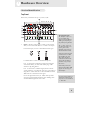
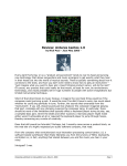
Here’s what you’ll find on the top of your IO|14/26:
MIC / LINE
The combo jack inputs
The XLR input “expects” to
see a microphone and
delivers between 6.8dB and
50dB of gain, depending on
the position of the gain knob.
1.
Inputs – The IO|14/26 features “combo” connectors that
allow you to connect either XLR or ¼” cables to the inputs.
For the IO’s inputs, use one of three different cable types:
Use XLR cables to connect to standard microphones.
For ¼” connections to balanced gear (like most keyboards
and sound modules), use cables with “TRS” plugs. TRS
stands for “Tip, Ring, Sleeve.”
For ¼” connections to unbalanced gear (like most electric
guitars and basses), use cables with “TS” plugs. TS stands for
“Tip, Sleeve.” These cables do not have the third wire which
TRS cables use to balance the audio signal.
Choose the right cable for the job. “TRS” cables provide a
stronger signal and significantly better noise shielding when
used with balanced gear than “TS” cables.
The ¼” input “expects” to
see either a line input or an
electric guitar or bass,
depending on the setting of
the Mic/Line/Guitar switch.
In the Line position, the input
provides between -15.4dB
and 27.8dB of gain. This
allows plenty of gain for
weak line level sources and
also provides the ability to
pad down overly powerful
line sources.
In the Guitar position, the
input provides 6.8dB to 50dB
of gain—the same range as
the XLR input.
If you’re not sure whether an
instrument is balanced, your
safest bet is to use a balanced
¼” TRS cable.
9
1
Hardware Overview
2.
Inserts – The IO|14/26 features “insert” jacks on every
analog input. These inserts allow you to place additional
equipment (like compressors, equalizers, etc.) into your signal
path using “insert” cables. Insert cables feature a ¼” TRS
connector on one end and two ¼” TS connectors on the
other end.. This jack is covered in detail on page 42.
3.
Mic/Line or Guitar Switch (Channels 1-2 only) –
Channels 1 and 2 of your IO|14/26 allow you to switch in a
specially designed, high-impedance circuit optimized for
recording an electric guitar or bass. If you’re recording a
microphone or a line-level instrument (keyboard, sampler, DJ
mixer, etc.) then set this switch to “Mic/Line.” If you’re
recording a guitar or bass with passive (standard) pickups, set
this input to “Guitar.”
4.
Gain Knobs – These knobs let you set the preamplifier gain
level. Set the gain with the aid of the meters on the front of
the IO14/26. Start with the gain knob turned all the way
down (counterclockwise); then slowly turn up the gain until
the green LEDs are often illuminated and the yellow LED
only illuminates when you play your loudest notes. At this
point.
If the red LED is lighting up (even occasionally), it means the
gain is set too high and that you’re distorting your signal.
Turn the gain knob back down as necessary in order to avoid
this distortion.
It’s OK to set your gain levels
conservatively with the IO|14
and IO|26. These interfaces
feature outstanding analogto-digital converters and
preamplifiers, allowing you
to capture excellent
recordings even if your
signals peak at -9dB (or even
lower).
Analog and digital distortion
are totally unrelated
phenomena.
Whereas certain kinds of
analog distortion (from
guitar amplifiers, stomp
boxes, etc.) can sound
pleasing, digital distortion
sounds awful. If your
IO|14/26’s meters are going
into the red (even every once
in a while), it means you’re
digitally distorting your
signal. Turn down the
channel gain in these cases.
10
Hardware Overview
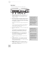
5.
1
Monitor Blend Knob – This knob controls the amount of
direct signal (from the analog and digital inputs) that gets
blended in to outputs 1/2. This direct signal monitoring
bypasses the computer for lag-free listening while tracking.
The levels and pan positions of each of the direct signals is
set using the “Hardware Direct Monitoring” program that
ships with the IO|14/26 (see page 35 for more about this
program).
When this knob is turned fully counterclockwise, the
Hardware Direct Monitor mix is muted, so you’ll only hear
the output being returned from your computer’s Digital
Audio Workstation. When the knob is turned fully clockwise,
you’ll hear the Hardware Direct Monitoring mix at full
volume as well as the signal coming back from your DAW.
6.
Metering Section – 5-segment “ladder” meters show the
precise, digital input signal for each analog channel.
Status lights indicate Firewire connection to the computer,
current sample rate, and ADAT input, S/PDIF input, and
MIDI activity.
Stereo output meters show the levels for outputs 1/2.
7.
Phones 1&2 Volume – The IO|14/26 has two separate
headphone outputs. These knobs let you set the volume for
each output.
8.
Main Level – This knob sets the output level of channels
1/2.
9.
Mic/Line or Phono Switch (IO|26 only) – Turntables
require special “phono” preamps that have higher gain and an
“RIAA equalization curve” in order to playback records
correctly. If you want to connect a turntable to your IO|26,
use the RCA “phono” inputs (on the rear of the unit) and
engage this switch.
Note that when you engage this switch, the top panel inputs
and gain controls for channels 7-8 are disabled.
10. Phantom Power – These switches let you supply +48v
“Phantom Power” to condenser microphones that require
power. Each button engages/disengages phantom power for
a pair of inputs (i.e., channels 1-2, 3-4, 5-6, and 7-8).
Phantom power is only
necessary for condenser
microphones. Dynamic
microphones do not need
power to work correctly.
Check your microphone’s
manual to find out if it needs
phantom power.
11
1
Hardware Overview
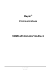
Rear Panel
You’ll find the following on the rear of your IO|14/26:
1.
2.
Headphone Outputs – Connect your headphones to these
outputs. The first headphone output always mirrors the
analog 1/2 output pair. The second headphone output is
assignable in software.
Main outputs (8 outputs on IO|26; 2 outputs on IO|14)
– Use ¼,” “TRS” cables to connect these outputs to the
balanced inputs of your powered speakers or power amplifier.
If your speakers or amplifier only provide unbalanced inputs,
use unbalanced (“TS”) cables.
The IO|26 (shown above) has 8 outputs. The IO|14 has 2
outputs.
If you are using the IO|26 and wish to connect additional
speakers, headphone amplifiers or hardware processors,
connect them to outputs 3 through 8.
3.
Phono input (IO|26 only) – Connect your turntable to this
input.
If your turntable has a grounding cable, attach it to the
grounding screw to the upper right of the phono inputs.
This grounding will minimize humming and buzzing.
4.
ADAT Lightpipe Inputs – These optical digital inputs
can accommodate a wide variety of ADAT-enabled gear.
The IO|14 has one ADAT input whereas the IO|26
(shown above) has two ADAT inputs.
Use ADAT-compatible optical cables to connect to these
inputs.
12
5.
S/PDIF Connectors – Connect S/PDIF-enabled digital
devices (such as the Alesis Masterlink, CD players, DAT
machines, MiniDisc Recorders, etc.) to your IO|14/26 using
coaxial, RCA-terminated cables.
6.
MIDI Connectors – Connect your keyboards, sound
modules, or other MIDI devices to your IO|14/26 using 5pin MIDI cables. Remember to chain the OUTs of each
device to the INs of other devices.
The IO14/26’s outputs are
“impedance balanced.” This
wiring method provides all of
the benefits of “fully
balanced” wiring when the
outputs are connected to
balanced gear. Furthermore,
impedance balancing, unlike
other balancing methods,
allows for trouble-free
connection to unbalanced
devices.
If you connect an ADAT or
S/PDIF input device (or
both), you will need to select
one of them as the “clock
master” in the IO’s control
panel.
The device you select as the
clock master will determine
the IO’s clock rate and will
be responsible for keeping all
of the digital signals
synchronized. Therefore, if
you turn this device off, you
will need to select another
clok master in the control
panel.
Hardware Overview
7.
8.
FireWire Connectors – Connect one of these plugs to your
computer’s FireWire port. You can use the other jack to
connect additional FireWire devices (such as hard drives) to
your computer. Up to 127 devices can be “daisy-chained” on
one FireWire bus.
Power Connector – Use the supplied AC adapter if your
computer does not provide sufficient Firewire bus power to
power the IO|14/26 or if you want to preserve battery
power.
1
If your Firewire cable comes
with one ferrite (a bulge in
the cable near the connector),
connect the end with the
ferrite to the IO|14/26, and
connect the end without the
ferrite to your computer.
Note that many notebook and small form factor computers,
like Mac Mini computers, do not provide sufficient power for
bus power. For these computers, the external adapter must
be used.
9.
Kensington Security Slot – This locking mechanism allows
you to secure your IO|14/26 to a desk or some other heavy
object using an optional third-party locking device.
If an AC adapter is attached,
the IO|14/26 will use it.
FireWire bus power is only
used if no AC power is
available.
Computers with noisy
internal power supplies can
send periodic, audible
pulsing through the outputs of
your IO|14/26. If you hear a
low-level pulsing, plug in the
AC adapter to bypass the
computer’s power supply.
13
1
Hardware Overview
This page intentionally left blank
14
2 Installation (Windows)
Important: Download and install the drivers from http://www.alesis.com-or insert the software CD into your computer’s CD drive—BEFORE you
plug your IO|14/26 into your computer for the first time.
Install the software/drivers first
Important: Follow these steps BEFORE you plug your IO14/26 into your
computer for the first time.
Begin by running the Alesis installer(s). These programs (there
may be one or more than one) will install three very important
components onto your computer:
•
Drivers. These are the system components
that allow Microsoft Windows to identify and
interact with your IO|14/26. You do not
interact with the drivers directly, but they must
be installed on your computer for the
IO|14/26 to work.
•
Control Panel. The control panel allows you to
set sample rates, clock sources, buffer sizes,
and other settings.
•
Hardware Direct Monitoring Panel. This
application lets you route the IO|14/26’s
inputs directly to its outputs for a minimum
of latency (delay) when recording.
The Hardware Direct Monitoring Panel also
allows you to change Headphone2 and
S/PDIF output assignments.
For each of the several installations that occur, click “Continue
Anyway” if Windows warns you that the drivers have not passed
Microsoft Logo Certification.
If you have access to the
Internet, check
http://www.alesis.com for the
very latest software updates.
The updates posted there are
guaranteed to be the most
current, best software
versions available.
Windows XP, Service Pack 2
or later is required.
The Windows drivers include
the two most popular
standards for audio
interfacing—WDM (the
“Windows Driver Model”
built by Microsoft) and ASIO
(the “Audio Stream
Input/Output” standard used
by many audio software
applications).
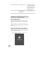
Windows Logo Certification warning.
Ignore this warning by clicking “Continue Anyway.”
15
2
Installation (Windows)
Install Cubase LE (optional)
If you are interested in using Cubase LE as your multitrack Digital
Audio Workstation, install it from the CD now.
Connect your IO|14/26
Now, connect your IO|14/26 to your computer using a Firewire
cable. Watch for one of the lights on the unit to turn on within a
few seconds. If a light does not turn on—or if you are using a
notebook computer with a small four-pin Firewire connector—
plug in the external AC adapter.
Windows will recognize the IO|14/26 and start the Found New
Hardware wizard. The installation process will automatically install
these drivers one by one.
When you are prompted whether to install the drivers
automatically or search for a specific location, choose to install
them automatically.
If you are asked whether you want to connect to the Internet to
check for the latest driver, choose not to.
Let the installer continue installing the various sets of drivers until
you see a message stating, “Your new hardware is installed and
ready to use.” Do not cancel any of the installations, as they are all
required for proper operation.
16
Installation (Windows)
2
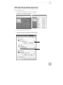
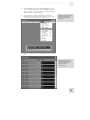
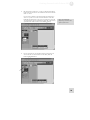
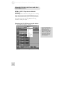
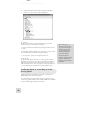
Make IO|14/26 the default audio device
To use your IO|14/26 interface as your default Windows sound
device, follow these steps:
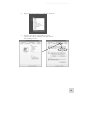
1.
From the Windows Start menu, choose “Control Panel.”
Depending on your Windows preferences, it will appear
similar to one of the two pictures below:
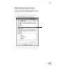
2.
Choose “Sounds and Audio Devices”.
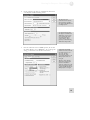
3.
Click the “Audio” tab. Change the default devices for both
sound playback and sound recording to your IO interface.
17
2
18
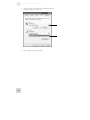
Installation (Windows)
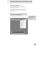
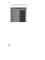
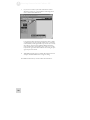
4.
Click the “Voice” tab. Change the voice playback and voice
recording settings to the IO|14/26.
5.
Click “Apply” to apply these changes.
Installation (Windows)
2
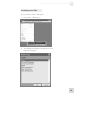
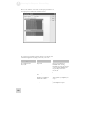
Disable Windows System Sounds
Windows System Sounds—the sounds that Windows plays to
signal starting up, shutting down, alerts and so forth—can interfere
with your audio recording. We strongly suggest that you disable
these sounds.
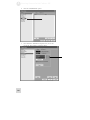
1.
Click the “Sounds” tab of “Sounds and Audio Devices.”
2.
Under “Sound Scheme,” choose “No sounds.”
3.
Click “OK” to accept this entry and close the dialog box.
19
2
Installation (Windows)
This page intentionally left blank
20
3 Installation (Macintosh)
Important: Download the drivers from http://www.alesis.com onto a folder
on your desktop or insert the software CD into your computer’s CD drive
BEFORE you plug your IO|14/26 into your computer for the first time.
Install the software/drivers first
Important: Follow these steps BEFORE you plug your IO14/26 into your
computer for the first time.
Begin by running the Alesis installer(s). These programs (there
may be one or more than one installer) will install three very
important components onto your computer:
•
•
•
Drivers. The CoreAudio and CoreMIDI
drivers allow your Mac to identify and interact
with your IO|14/26.
Control Panel. Access the Control Panel from
Audio/MIDI Setup’s “Configure Device”
button. The control panel allows you to set
sample rates, clock sources, buffer sizes, and
other settings.
Hardware Direct Monitoring Panel. This
application lets you route the IO|14/26’s
inputs directly to its outputs for a minimum
of latency (delay) when recording.
The Hardware Direct Monitoring Panel also
allows you to change Headphone2 and
S/PDIF output assignments.
Install Cubase LE (optional)
If you are interested in using Cubase LE as your multitrack
Digital Audio Workstation, install it from the CD now.
If you have access to the
Internet, check
http://www.alesis.com for the
very latest software updates.
The updates posted there are
guaranteed to be the most
current, best software
versions available.
Mac OS X 10.4 or later is
required.
Your CoreAudio application
may describe the IO|14/26
channels simply as “1, 2, 3,
4, etc.” Note that, if you are
using an IO|14, the S/PDIF
channels will not appear at
the end of the channel list but
rather at an earlier position.
Connect your IO|14/26
Now, connect your IO|14/26 to your computer using a Firewire
cable. Watch for one of the lights on the unit to turn on within a
few seconds. If a light does not turn on, plug in the external AC
adapter.
Important: If you experience problems when using a 4-pin Firewire cable
(small connector) to connect the interface to your laptop computer, we
recommend that you either switch to higher quality cables or install a six-pin
PC card adapter into the notebook.
21
3
Installation (Macintosh)
Make IO|14/26 the active audio device
Open Audio/MIDI Setup and choose your IO|14/26 for both
your inputs and outputs.
22
4 Getting Started with Cubase LE
Introducing Cubase LE
Your IO|14/26 ships with Cubase LE, a powerful audio and
MIDI Digital Audio Workstation.
The following instructions are designed to get you set up and
recording audio with Cubase LE quickly. For more information on
using this software, consult the documentation available in
Cubase’s Help menu.
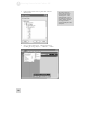
Windows only: selecting the IO|14/26 as
your audio and MIDI device.
1.
Choose the menu option “Devices” | “Device Setup….”
For Mac users, the audio
device used by Cubase is the
same one that you select in
Audio/MIDI setup.
23
4
24
Getting Started with Cubase LE
2.
Click the “VST Multitrack” option.
3.
From within the ASIO Driver drop-down box, choose the
IO|14/26. Press Apply to accept the change.
Getting Started with Cubase LE
4.
To enable MIDI, click on the “Default MIDI Ports” option
on the left-hand side and select IO|14/26’s MIDI ports for
input and output. Again, click “Apply” to accept the changes.
Then press “OK” to exit this screen.
5.
Now that the IO|14/26 is selected as the audio device,
individual channels must be activated for use. Again, return
to the “Devices” menu, and select “VST inputs.”
6.
Click the activation buttons for channel pairs that you want to
use.
4
Different versions of Cubase
function similarly, but not
exactly, to the examples
shown here.
Some versions of Cubase,
including Cubase LE, do not
allow all of the physical
inputs to be used
simultaneously.
25
4
Getting Started with Cubase LE
7.
26
In Cubase, you can rename channels by clicking in the
“Label” area. This is useful if, for instance, your lead vocals
are always on channel 1, your bass drum is always on channel
2, etc.
Getting Started with Cubase LE
4
Creating a new file
Now, you’re ready to create an audio project.
1.
Choose “File” | “New Project…”
2.
You can begin with a template or an empty file. For now,
begin with an empty file.
27
4
28
Getting Started with Cubase LE
3.
Cubase needs to know where to place audio. Choose a
directory here.
4.
Now, you have a blank project. Add an audio track for
recording by choosing “Project” | “Add Track” | “Audio.”
An excellent scheme for
storing your projects is to
create a directory called
“audio projects.” Then,
within that folder, create a
new folder for each song you
work on. Cubase will store
your song file and all
associated audio files in that
same folder.
Getting Started with Cubase LE
5.
Be sure that the “inspector”—a strip on the left-hand side of
Cubase that shows all sorts of information about the selected
track—is active.
If your view is similar to that shown below, the Inspector is
active. If you do not see all of the information on the lefthand side, the Inspector is not active. To activate it, press the
“show Inspector” button towards the upper left of the screen
(just below the “Edit” menu in the following picture).
6.
4
Later, you can hide the
Inspector if you want to save
space on your screen.
Choose an input for your track by selecting it from the “in”
area on the left. To record stereo on the track, click the
button highlighted below.
29
4
Getting Started with Cubase LE
7.
If you want to monitor your audio with Cubase’s effects
(distortion, reverb, etc.), press the direct monitoring button
next to the Record Enable button.
Using Cubase’s direct monitoring requires the audio to make
a round-trip through the computer, which causes a small but
noticeable delay as the digital audio is processed. To avoid any
echo effects, open the Alesis Hardware Direct Monitoring
panel and mute the corresponding input. This way, you will
only hear the signal with effects without also hearing the pure
signal output from the IO.
8.
Add additional audio tracks as needed. Record-arm each one
and press the RECORD button to begin recording.
For additional information, consult Cubase’s documentation.
30
5 Using the Control Panel
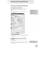
Working with the IO14/26 control panel
Accessing the control panel
In Windows, open the control panel from the shortcut on your
desktop, the Programs menu, or from within your audio
application.
On the Mac, access this panel from the “configure device” button
of Audio/MIDI Setup.
To open the control panel
from within Cubase in
Windows, select “Devices” |
“Device Setup….” | “VST
MultiTrack.” Then, click the
“Control Panel” button.
1. Select the Alesis IO.
Be sure that your IO14/26 is shown here. If it is not shown, then
your computer does not “see” it. Check the IO’s connections to
your computer.
2. Create a nickname for your IO|14/26
(optional)
You can change the name of the IO|14/26 as it’s seen by the
recording program.
Once this is done, choose “Reset All” in Cubase (or the equivalent
command in other programs) to update the display of the device
and channel names.
Creating a nickname for your
device is entirely optional.
31
5
Using the Control Panel
3. Adjust latency by changing the buffer
size
“Latency” refers to the amount of time it takes for audio to get
into and out of the computer. In the best of all possible worlds,
there would be no such thing as latency—we would hear audio the
moment it was created. However, computers have limited
processing power, and they can “choke”—cutting off recording or
crashing programs—if they are asked to handle too much data all
at once.
To minimize this risk, audio can be stored in a buffer for a certain
amount of time. This buffering helps smooth out the stream of
data that the computer needs to handle. In the end, all of the
audio is sorted out and played correctly, but with a delay.
Here are the basic considerations to consider when adjusting
buffer sizes:
Lower buffer size = less latency but higher risk of audio
problems
Higher buffer size = more latency but lower risk of audio
problems
To counteract the delays you
hear when you are
monitoring incoming audio
through the computer and
your latency settings are
high, turn off your DAW’s
input monitoring feature.
Use the included Alesis
Hardware Direct Monitoring
application instead.
Very high buffer size = possible system instability
For most systems, there is a “sweet spot” where latency is not too
high and system performance is stable. Experiment with raising or
lowering buffer sizes to hit this sweet spot.
As you begin adding plug-in EQ, compression, and so forth to
your project, your computer will need to work harder. Consider
increasing your buffer size at this time.
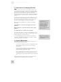
4. Choose a Buffer Mode
Three different modes allow you to customize the way that your
computer organizes and uses buffers.
-
If you use your computer for all sorts of applications besides
music (Word Processing, email, etc.), choose “Norma”l
Buffer Mode.
-
If your computer is relatively new and is used almost
exclusively for music applications and has very few other
processes running, choose “Fast” mode.
-
Choose “High Performance” mode if you have an extremely
well specified computer, use few background tasks, and are
not shuttling very large amounts of data through the Firewire
bus.
Experiment with each of these settings in your first few weeks
using the IO14/26. Depending upon your computer
32
Many people use two latency
settings—a lower one when
recording tracks and a higher
one when mixing.
Using the Control Panel
5
configuration and the types of audio projects you do, you may find
that one setting clearly outperforms the others.
5. Specify how sample rates can change
Since Windows (and various Windows applications) have a nasty
tendency to try and take control over your audio sample rate—
often without notice—this section allows you to ignore those
sample change events.
-
If you do not mind your sample rate changing freely, choose
“Allow SR Changes.”
-
To allow only ASIO applications (like Cubase) to change the
sample rate, select “Allow ASIO changes only.”
-
You can lock the sample rate—such that it can only be
changed using this control panel—by selecting “Apps cannot
change SR.” This is the safest of all these options.
Whichever setting you choose, the sample rate can always be
changed from within this control panel. Note, however, that if
you have an audio application open, you can cause conflicts with it
if you try to set the sample rate differently here compared to the
setting in the open audio application.
6. Enable or Disable WDM audio
(Windows only)
If you are using ASIO applications exclusively and do not need
access to Windows system sounds, Windows Media Player or other
media players, consider unchecking this box. Doing so helps
ensure that unwanted audio from other applications does not
intrude on your intended audio output.
7. Set the clock master
If you are using multiple Firewire audio devices at once, chain one
to the next, and designate the one at the beginning of the chain as
the clock master.
8 Specify the audio clock source
In digital recording systems, all digital input devices must be
synchronized to the same clock. For IO|14/26, this means that
you need to take care to set the clock source properly when you
use either the S/PDIF or the ADAT inputs.
1.
INTERNAL. Use this setting if:
a. You are not connecting any external S/PDIF or
ADAT input devices;
b.
You are connecting external S/PDIF or ADAT
input devices, but you are running a cable from the
IO|14/26’s S/PDIF output into one of these
devices. This is a rare case.
If you’re using the IO|14/26
by itself, you don’t need to
worry about clocking. Just
make sure that the “Clock
Source” parameter in the
IO|14/26’s control panel is
set to “Internal.”
If you’re connecting your
IO|14/26 to other equipment
through the ADAT or S/PDIF
connections, keep in mind the
following rule of digital
audio:
When connecting devices
digitally, all of your devices
must be locked to ONE clock.
33
5
Using the Control Panel
2.
S/PDIF or ADAT. Use one of these settings if you have
attached either a S/PDIF or ADAT device.
If you have attached more than one of these devices,
synchronize their clocks using dedicated cables; then choose
one of the as the clock master.
Note that ADAT2 on the IO|26 cannot be the clock master.
If you are only using one ADAT input on the IO|26, use the
first input. If you are using both ADAT1 and ADAT2 with
two different hardware devices, be sure to clock one device to
the other.
3.
FIREWIRE. Use this setting if you have another Firewire
audio devices connected to the IO14/26 and you want that
device’s clock to drive the IO14/26’s clock. No additional
cables are necessary—the IO14/26 will read the clock signal
coming from the other device over the Firewire cable.
Start with one device and
cable its Word Clock Output
to the Word Clock Input of
the second device. If you
have a third device, connect
the second device’s Word
Clock Output to the third
device’s Word Clock Input.
Your IO|14/26 includes a state-of-the-art clock recovery circuit
that generally eliminates clocking-induced glitch artifacts even
when clock sources are incorrectly assigned. Nevertheless, do take
care to assign the clock source correctly. Otherwise, sample
accuracy is likely to suffer.
For each device, if there is a
“master/slave” setting, be
sure to set it appropriately.
(Only the first device in the
chain should be the
“master.”)
9. Set the sample rate
There are other ways to lock
your clocks together, such as
using a dedicated clock
distribution hardware device.
However, the method
outlined here is perfectly fine,
as well as being the most
simple and economical.
Set the sample rate here. Note that this setting must be made even
if you are using an external device (ADAT, S/PDIF or Firewire) as
your clock master.
Some audio programs require that you change the sample rate
under their Project Setup or similar menus as well. For instance, in
Cubase, be sure that the sample rate selected here matches that
under the “Project” | “Project Setup…” menu.
34
When you use two or three
digital input sources, lock the
devices together. Most
commonly, you will use the
devices’ BNC Word Clock
connectors for this purpose.
To ensure S/PDIF lock, set
the clock source and sample
rate in the Alesis control
panel before connecting,
powering on, or changing the
sample rate of your S/PDIF
device.
6 Hardware Direct Monitoring
The Alesis Hardware Direct Monitoring
and Routing Application
A powerful digital mixer is built into your io. This digital mixer
allows you to route your analog and digital inputs directly to the
outputs, completely bypassing the computer. This hardware-based
routing allows musicians to monitor their performances with no
perceptible delay.
There may be times when you find this functionality to be
unnecessary. For instance, when you are recording simpler
projects that put less strain on your computer, you can generally
choose lower buffer settings in the Alesis IO control panel. This
way, you can use the input monitoring feature of your DAW
recorder, and the latency (delay) experienced by your performers
will be very slight.
However, when you add more tracks and plug-ins, you will need to
increase your buffer sizes in order for your system to keep
operating smoothly. At this point, it makes sense to mute the
Input Monitoring on your DAW and use the IO14/26’s digital
mixer.
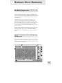
Using the Hardware Direct Monitoring
(HDM) panel
Once you have connected all your recording gear and established a
computer connection (as shown by the light on the io), open the
Alesis Hardware Direct Monitoring and Routing panel by clicking
on the shortcut on your desktop.
35
6
Hardware Direct Monitoring
1. Output Monitor Tabs
Use these tabs to select the output pairs to which you will blend in
the incoming signal. Each tab’s HDM mix is completely separate
from the others.
Setting up direct monitor mixes for single musicians and for
multiple musicians
Most commonly, you’ll have a stereo set of speakers attached to
outputs 1/2. This is the output pair to use for your Digital Audio
Workstation’s stereo outputs.
If you are recording a single musician, connect your inputs, and
then select the tab for outputs 1/2. Now, you can easily blend in
the musician’s direct audio with the music coming back from the
Digital Audio Workstation.
When you are recording multiple musicians—each of whom
desires a different monitor mix—use these tabs to create a separate
“monitor mix” for each output pair.
Experiment with creating multiple mixes—doing so puts no strain
on your computer.
Re-naming the tabs
You can re-name each of
these tabs by double-clicking
on them and entering your
new name. (Names like
“Singer” and “Drummer”
can be a lot more helpful than
“Out 3-4.”) Note that the
names you type will not alter
the physical routing taking
place in the IO14/26.
At 176.4k and 192k sample
rates, hardware direct
monitor mixes can only be
heard on outputs 1-4. Audio
will play back from the
computer as normal on all
the channels, but the analog
and digital inputs cannot be
monitored on outputs 5-8.
2. Pan/Mute/Solo
Set the left/right pan position of the audio here. Also, you can
solo and mute individual channels.
Using the Shift key, click the pan knob to return it to center. Also,
hold down Shift while clicking to mute or solo (or un-mute or unsolo) all of the inputs at one time.
3. Volume
Set the volume using this slider.
4. Stereo Channel Linking and Unlinking
Use this button to link or unlink the controls for stereo channel
pairs.
5. Channel Names
Just like the output tabs, the incoming audio channels can be renamed. (Words like “vox” and “snare” probably have more value
than “Analog1” and “ADAT12.”) The names you provide carry
over to all of the tabs.
6. Master HDM Mix Fader
This is the master fader for the Direct Monitor mix for this output
pair. Bringing this fader up or down affects all the channels being
monitored using HDM but does not affect the audio coming back
from the computer.
Once you have set your balances for multiple instruments using
the individual slider, this control allows you to bring your whole
mix into balance with the audio from your Digital Audio
Workstation.
36
If you hear the input signal
twice—with a short delay
between each instance—
then you are most likely
monitoring through both the
HDM panel and also your
DAW software. Either turn
off input monitoring on your
DAW or mute the
corresponding input on the
HDM panel.
Hardware Direct Monitoring
6
For outputs 1 and 2, the MIX BLEND knob on the front panel of
the hardware can also be used to control this slider.
7. Narrow/Wide View Switch
You can switch between “Narrow” and “Wide” views of the
HDM panel. Note that the Input Monitor tab is always in Narrow
mode.
8. Metering Options
Choose from a number of different metering options here.
Meter Scale
Under “Meter Scale,” choose “High,” “Medium,” or “Safe.” These
options change the thresholds at which the meters change to
yellow and then to red. WHATEVER SETTING YOU
CHOOSE, THE ACTUAL AUDIO BEING RECORDED IS
UNTOUCHED. Rather, these modes can help keep you from
recording too “hot,” resulting in digital “overs.”
Peak Hold time
Set how long the highest peak of the incoming audio should be
displayed.
Peak Reset
Click this button at any time to reset the peak levels of the meters.
9. Bank Hide/Show buttons
In “Wide” mode, not all channels are visible at once. If you are
not using some of your channels, choose to hide them.
Note that these buttons are grayed out in “Narrow” mode.
10. ADAT-S/PDIF Toggle
The HDM mixer can mix 24 inputs. At 44.1kHz and 48kHz, the
io|26 offers 26 inputs, 2 more than the total. Therefore, at these
sample rates, choose to monitor either ADAT 15/16 or S/PDIF.
The metering options do not
change how audio is actually
recorded. They only change
how the audio is metered on
screen.
For highly unpredictable
audio (live concerts, maniac
drummers, etc.), consider
using “Safe” metering and
trying to keep your audio in
the yellow area of the meter
scale. Then, if an
unpredictable audio event
occurs, your audio is more
likely to be recorded cleanly.
For predictable dynamic
sources, like distorted electric
guitar or sources where
you’ve inserted a hardware
limiter in the recording path,
don’t be afraid to push your
meters up into the red zone.
(Red in this panel means
“caution,” not “uh-oh!”)
Your choice here will not affect the number of channels seen by
your DAW. Your DAW will always see all IO|14/26 channels.
This choice only affects the audio that you monitor through this
HDM application.
If you still need to monitor those last two channels, you can always
do so through your Digital Audio Workstation software, though
some increased latency will result.
11. Main Level
The position of the MAIN LEVEL(outs 1/2) knob is indicated
here for convenience (Windows only).
37
6
Hardware Direct Monitoring
Numbers 12 through 15: Load/Save and Audio Routing Settings
12. Save/Recall Settings
Your HDM settings will only be recalled if you save them. Save
them as “default.hdm” and they will be recalled every time that the
panel is opened. Save setups that you want to recall for specific
sessions under some other name.
13. Device Configuration (Control Panel
shortcut)
Click “Device Configuration” to go immediately to the IO14/26
Control Panel, where you can set the sample rate, clock master,
device nickname, etc.
14. Headphones 2 Assignment
The first set of headphones always follows the Out 1/2 mix. The
second pair of headphones is freely assignable to follow any of the
analog output pairs.
15. S/PDIF output assignment
The S/PDIF digital output, like the second headphones output,
can be assigned to follow any output pair.
For the IO|26, these output
pairs all correspond to
physical, line-level outs.
They all exist in hardware.
While the IO|14 only has one
stereo pair of line-level
outputs, the IO|14 reports
these additional output pairs
to your Digital Audio
Workstation. These
additional pairs allow you to
make headphone 2 and
S/PDIF assignments to more
than just the built-in stereo
output.
This “virtual” routing
providesIO|14 owners with
much of the power of its big
brother, the IO|26.
The S/PDIF output mirrors
the volume of the analog 1/2
outputs.
Changes made to the main
volume encoder on the front
of the unit, and changes made
to the +4/-10 output level
switches on the Hardware
Direct Monitoring
application, will change the
level of the S/PDIF output.
38
7 Getting In Deeper: Hardware
Cabling 101
Cables are a crucial (and often overlooked) part of a studio. Many
beginners run into problems because they use inappropriate or
poor quality cabling to connect their gear and their recordings
suffer as a result. Don’t let this happen to you! Use the following
guidelines to maximize your sound quality:
1.
Use balanced cabling wherever possible – The IO|14 and
IO|26 are fully balanced recording devices that will give you
the best sound quality when using “balanced” cabling
wherever possible. Technically speaking, balanced cables
carry your signal over three conductors (known as “hot”
“cold” and “ground) as opposed to “unbalanced” cables
which only have two conductors (known as “hot” and
“ground”). Because of this design difference, balanced
cables pick up much less radio frequency (RF) and
electromagnetic (EM) noise. Musically speaking, this means
you’ll have much less unwanted humming, hissing, and
buzzing noises in your recordings.
2.
Minimize Cable Length – As your cable length increases, so
does your signal’s susceptibility to unwanted noise. Try to
minimize your cable runs as much as possible to preserve
sound quality. Don’t sweat over minor differences in length
(i.e., using 20’ of cable when you only need 15’), but definitely
don’t use a 100 ft. cable if all you need is 10 ft.!
3.
Use High Quality Cables – Not all cables are the same!
Try to use well constructed, high-quality cables whenever
possible. Two cables may look the same on the outside, but a
high quality cable will have better shielding and soldering on
its connectors. This means a good cable will perform better
and last much longer than a cheap one.
4.
Keep ‘em separated! – Try to keep your audio cables and
power cables separate from each other. Power cables tend to
emit lots of electromagnetic noise and if you bunch all of
your cables together to make them look tidy, you’re increasing
the noise that is picked up by your audio cables. Group your
cables in two bunches if possible (i.e., an “audio” group and
an “other” group) and keep these groups separate. Even a
few inches between the two groups will substantially cut
down on noise. If your power and audio cables need to cross
paths, have them do so at 90 degree angles to minimize
contact.
39
7
Getting In Deeper: Hardware
Common Hookup Scenarios
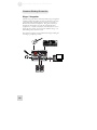
Singer / Songwriter
The following setup will be commonly used by singer/songwriters
working in their home studios. It allows for the artist to hook up
guitars, keyboards, and microphones to the IO|14/26 and to
monitor him/herself on headphones. The guitar, keyboard, or
microphone shown below can easily be swapped with other
equipment (i.e., samplers, CD players, more microphones, etc.) to
match the artist’s needs. All of the arrows indicate analog ¼” or
XLR cabling unless otherwise noted.
Note that the computer can be replaced with a laptop making the
recording rig completely portable.
40
Getting In Deeper: Hardware
7
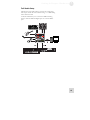
Full Studio Setup
The following setup makes full use of the IO|14’s audio inputs
and outputs. All of the arrows indicate analog ¼” or XLR cabling
unless otherwise noted.
An IO|26 would allow you to connect four additional analog
inputs as well as 8 additional digital inputs via a second ADAT
port.
41
7
Getting In Deeper: Hardware
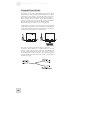
Using the Insert Jacks
Sometimes, you may want to add additional gear into your signal
path before your analog-to-digital converter digitizes your signal
and sends it to the computer. For example, many bass players
like to compress their instrument with an analog compressor
before recording into the computer. Inserts help you do this by
letting you tap into your signal after the IO|14/26’s preamplifier
but before the A/D converter. The two diagrams below
demonstrate where the inserts fit into your signal path.
In the diagram to the left, no insert is used and your signal passes
straight from the preamp to the A/D converter. In the diagram
on the right, an effects processor is inserted into the signal path
just after the preamp (before the A/D converter).
Note that you need a special “insert cable” to utilize this
connection. These cables have a ¼” TRS connector on one end
and two ¼” TS connectors on the other end. The TRS side goes
into the “insert” jack on the IO|14/26. The two TS connectors
are usually labeled “send” and “return.” The “send” plug goes to
your external device’s input whereas the “return” plug connects to
the device’s output.
42
Getting In Deeper: Hardware
7
Additional Uses of Insert Jacks
Inserts can be used in two additional ways that you may find
useful. They are as follows:
1.
Using the IO|14/26 as a preamplifier – In certain
situations, you may want to use the IO|14/26’s preamps by
themselves. For example, if you’re recording a performance
onto an external hardware recorder (such as an Alesis HD24)
but you need more preamplifiers, you can use an insert’s
“send” cable to send your preamplified signal to the recorder
and simply not use the “return” connection on the insert
cable.
2.
Bypassing the IO|14/26’s preamplifier – The IO|14/26
has excellent sounding preamplifiers built in, but if you have
a megabucks or vintage preamp that you want to use instead,
experiment with connecting it to the insert jack. The insert
jack allows you to use your external preamp while completely
bypassing the IO|14/26’s built in preamplifier.
To bypass the IO|14/26’s internal preamplifier, connect the
“return” of the insert cable to your external device. Leave
the “send” of the insert cable disconnected.
Doing this will unbalance the external preamplifier’s signal.
In most cases this is not a problem, but check with your
preamplifier’s manufacturer for any noise, level, or grounding
concerns before connecting your equipment in this way.
43
7
Getting In Deeper: Hardware
This page intentionally left blank
44
8 Getting In Deeper: Recording
Watch Your Levels While Recording
A basic principle in digital recording is that you want to capture the
loudest signal you can, but at the same time you never, ever want
to exceed the maximum digital threshold. If you do, you’ll
introduce the nasty distortion known as “digital clipping” into your
recording.
Your Alesis IO provides a number of methods to help you avoid
digital clipping:
1.
24-bit recording - Operating at 24 bits, the IO offers 256
times more resolution than that of 16-bit compact disks.
One result of that increased resolution is that you have far
more headroom to work within. You can easily record such
that your loudest peaks for an unpredictable player are no
greater than -12dBfs to -18dBfs. (“dBfs” stands for “decibels
at full scale”. In digital, once you reach full scale, you’re using
all of the available resolution. Attempting to record at
greater than 0dBfs results in digital clipping.)
2.
Dedicated hardware metering of digital signal - The
meters on the front panel of the IO show your audio signal
as it is seen by the digital converters. In other words, they’re
totally accurate, unlike analog meters which only approximate
the digital signal strength.
3.
Dedicated input monitoring panel - In the HDM
application, there is a special tab for Input Monitoring. This
tab provides an uncluttered view of the strength of your
incoming signals. (Note that the tab is always in “narrow”
view to provide a quick overview of all the channels.)
4.
Pre-fader level monitoring - Again in the HDM application,
all metering is always “pre-fader.” That means that the
metering shown to you is independent of how you set the
volume sliders. This allows you to see your actual signal
strength even as you’re creating various custom mixes for the
people you are recording.
If you haven’t experienced
digital clipping before, spend
a moment to learn what it
sounds like. Plug a
microphone or line level
source into your IO. In the
HDM panel, turn up the fader
for that channel in an
appropriate output tab. Be
sure that the “Direct Mon”
slider towards the right is
turned up as well. You want
to hear your audio.
Watch the HDM panel
metering, and turn up the
IO’s preamp until you’re
registering signals near the
top of the scale. Then, go just
a bit further. Notice the
harsh, buzzing kind of
distortion that appears. This
distortion is digital clipping.
It can ruin your recordings
and should be avoided at all
costs (unless you want it as a
special, unmusical effect).
45
8
Getting In Deeper: Recording
Base Sample Rates: 44.1/88.2/
176.4kHz versus 48/96/192kHz
There are two “base” sampling rate standards in the world of
professional audio—44,100 samples per second (44.1kHz) and
48,000 samples per second (48kHz). Broadly speaking, audio CD’s
operate at 44.1kHz, while film and television operate at 48kHz.
High definition sample rates—including 88.2kHz, 96kHz,
176.4kHz, and 192kHz—are all simply multiples (doublings and
quadruplings) of the 44.1kHz and 48kHz standards. The IO14/26
offers all of these sample rates.
If you’re unclear on what base sample rate to use, consider this
guideline:
•
If your recordings are slated for release on CD, MP3,
Casette, Vinyl, etc. set your sampling rate to 44.1, 88.2,
or 176.4k for best results.
•
If your project is slated for DVD, film, or television, set
your sampling rate to 48, 96, or 192k for best results.
If you’re working on a commercial project and you’re not sure
what rate to use, ask your technical supervisor before you begin
working.
High Resolution Recording
The Upside of High Definition recording
Recording at high definitions (i.e., anything at 88.2k or above)
means you’re capturing sound at well beyond the range of human
hearing. Doing so has three sonic advantages:
1.
At the Hardware Level: All analog-to-digital converters
need to heavily filter your signal’s highest frequencies to
prevent a nasty form of distortion called “aliasing” from
taking place. Only sounds above the sampling limit are
removed, but the filter itself causes unwanted phase-shifts
that some critical listeners can hear (mind you… these are
quite subtle changes in your audio)
When you’re recording in HD, the anti-aliasing filter is much
more gradual and set at a very high frequency (well over the
upper limit of human hearing). This all but eliminates any of
the phase distortion that you may have heard.
2.
46
At the Software Level: Since software plugins such as
equalizers and compressors have more sample data to work
with, carefully programmed plugins can sound better.
Changing base sample rates
mid-stream in projects is
fairly straightforward in most
DAW programs. However,
doing so may cause very
slight but still audible
degradation of your audio.
Getting In Deeper: Recording
3.
8
Archiving: If you’re capturing a special recording that may
have some historical value in the future, it makes sense to
capture it with the highest level of technical accuracy.
Alesis has designed your IO14/26 to sound excellent at all
sample rates. Decide for yourself if the benefits and
tradeoffs are worth it for a particular session.
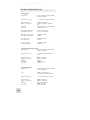
The Downsides of High Definition Recording
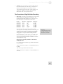
1.
Disk Usage – Recording at high sample rates consumes hard
disk space much more quickly than standard rates. The
following table describes sampling rate vs. disk usage for a
60-second snippet of monophonic (1 track) audio:
Length
60 Seconds
60 Seconds
60 Seconds
60 Seconds
60 Seconds
60 Seconds
Bit Depth
24 bit
24 bit
24 bit
24 bit
24 bit
24 bit
Sampling Rate
44.1k
48k
88.2k
96k
176.4k
192k
Disk Usage
7.9 MB
8.6 MB
15.9 MB
17.3 MB
31.8 MB
34.6 MB
You can see how this may become a problem on large
musical projects. For example, whereas a 5-minute song with
16 channels of 24-bit audio would require up to 635MB to
record at 44.1k, the same song would need approximately
2.54 gigabytes of storage if you’re recording at 176.4k!
Please note:
At quad sample rates (176.4k
and 192k), only inputs 1-4 of
the IO|26 are operational.
We recommend that you take a look at your available hard
disk resources when deciding which sampling rate to use.
You can use the following formula to estimate the total disk
space required for a song:
Song length (in seconds) X Number of Channels X
Sampling Rate X 3
So… Our hypothetical 5-minute song would be calculated in
the following way:
300 sec x 16 channels x 44,100 x 3 = 635,040,000 byes (about
635 MB)
That same song recorded at 176.4k would be:
300 sec x 16 channels x 176,400 x 3 = 2,540,160,000 bytes (or
2.54 GB)
47
8
Getting In Deeper: Recording
Geek talk: Why do we multiply by 3?
We have to multiply our disk usage by 3 because we assume you’ll be recording at 24 bit. One
“byte” of disk space contains 8 “bits” of information. Thus, if you are recording at 24-bit
resolution, you’ll need 3 bytes to contain all of that sample data (since 3 x 8 = 24). This is why
your disk usage must be multiplied by 3.
If you were recording at 16 bit (which we do not recommend due to the reduction in sound
quality) you would only multiply your total by 2 since a 16 bit sample only needs 2 bytes to
describe the sample (2 x 8 = 16).
If all of this sounds like Martian to you—don’t worry. You don’t really need to know this stuff and
there’s no quiz at the end of the manual!
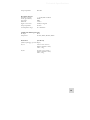
2.
Processor Usage – A second drawback of recording in high
definition is that you’ll use substantially higher amounts of
CPU resources. This is because your computer processor has
to deal with twice as many samples operating at 88.2k than it
does when processing at 44.1k and four times as many
samples when recording at 176.4k. The following
hypothetical scenario should clarify:
Sample Rate
44.1/48k
88.2/96k
176.4/192k
Maximum Plugins you can
run on your computer
40
20
10
If you generally don’t use many audio tracks and plugins, this
won’t affect you very much. If you use tons of audio tracks
and plugins, this may tilt you in favor of recording at a lower
sampling rate (or get a faster computer if you insist in
recording in HD).
3.
48
Fewer ADAT optical inputs – If you’re using an external
analog-to-digital converter to add more inputs to your
IO14/26, you can add 8 (IO|14) or 16 (IO|26) channels at
44.1 or 48k, but you can only add 4 channels of 88.2k or
96k audio.
The ADAT2 port on the
IO|26 is only operational at
44.1k and 48k sample rates.
Getting In Deeper: Recording
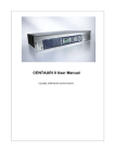
8
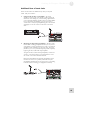
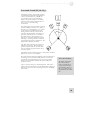
Surround Sound (IO|26 only)
The IO|26’s 8 analog outputs make it perfect
for multichannel surround-sound applications
(such as sound for film, TV, or DVD). If
your software supports surround mixing,
simply hook up your speakers to the IO|26
and refer to the software’s documentation on
how to set up a surround mixing
environment.
Note that there are several common surround
formats including 4-channel (a.k.a. “quad”), 6channel (“5.1”), and 8-channel (“7.1”). There
are also many non-standard and “custom”
mixing scenarios and every situation has its
own rules and requirements on speaker type,
placement, and other factors. It would be
beyond the scope of this manual to cover
each type of surround configuration, but the
following “5.1” mixing scenario is commonly
used and will work for most applications. The
diagram below illustrates the setup:
The “Mix” circle represents the “sweet spot”
where the engineer sits. The left and right
speakers are positioned 30° off center. The
rear two channels are positioned 135° off of
the center speaker.
The distance from the mixing engineer to each speaker should be
identical (or as close to it as possible).
Note that subwoofer placement depends on the size and shape of
the mixing room. The sub should be placed in a location that
provides the most linear frequency response. This generally
requires some trial-and-error before the optimal subwoofer
position is located.
Again, if you’re working on a commercial project, make sure to
speak to the supervisor and iron out the details before jumping in!
This may save you from time-consuming conversion or remixing
in the future.
More on Surround Mixing
The Grammy organization
has excellent (and free)
resources available on the
web for people interested in
surround mixing. Please see
http://www.grammy.org/pe_w
ing/guidelines/for more about
this.
49
8
Getting In Deeper: Recording
Using the IO14/26 with Sonar and other
WDM applications
WDM or ASIO? Experiment with both
protocols
An increasing number of Windows audio applications—including
Sonar—offer a choice of either ASIO or WDM operation. It’s
worth experimenting with the two different modes of operation.
ASIO will often (but not always) prove to be the superior choice.
For applications that only work using WDM, the following
instructions should prove helpful.
Choosing the IO14/26 as your audio device
1.
Choose the menu “Options” | “Audio….”
Unlike ASIO, WDM allows
different audio devices to be
used at the same time.
However, doing so can cause
synchronization problems.
Therefore, we suggest that
you use the IO14/26 as your
sole computer-connected
audio input/output device
when using WDM.
50
Getting In Deeper: Recording
2.
8
On the “General” tab, select any available IO14/26 channels
as the Playback and Record timing masters.
This discussion uses
Cakewalk’s Sonar software,
but the principles provided
here apply to all WDM-based
recording software.
For applications like Sonar
that support both WDM and
ASIO modes, you may want
to experiment with each to
see if either mode offers
greater stability. Alesis
generally recommends using
ASIO mode when possible.
3.
Click the “Advanced” tab. For WDM operation, be sure that
the “Driver Mode” is set to “WDM/KS.” (If you change this
setting, you will need to exit and then restart Sonar.)
A limitation of the WDM
architecture is that, each time
you change between “low”
(44.1/48), “medium”
(88/2/96), and “high”
(176.4/192) sample rates, the
WDM profiler needs to be
run again.
Therefore, when changing
amngst these sample rates,
first close SONAR,then
change the sample rate on the
Alesis control panel. Finally,
re-open SONAR and allow its
WDM profiler to run again.
51
8
Getting In Deeper: Recording
Move to the “Drivers” tab. Click on each input pair and also on
the output pair to make them available to Sonar.
If you’re having problems operating the IO|14 or IO|26, this
troubleshooting index may help you resolve your issues.
Symptoms
No sound from the
IO|14/26.
52
Cause
Solution
No power.
Plug in power adapter or
FireWire cable. If using
FireWire bus power, be sure that
your computer’s FireWire port
can provide power to the
IO|14/26.
Main Output level set too
low.
Raise the MAIN LEVEL knob.
Speakers (or amplifier) is
turned off or down.
Turn speakers (or amplifiers) on
or up.
Headphone level is too low.
Turn up the PHONES knob for
your headphone output.
Technical Specifications
Audio signal is distorted.
Cables not hooked up
properly.
Check outputs to make sure
cables are plugged in correctly
(and securely).
Bad cable(s).
Check all cables; substitute
cables with known good ones.
Channel input gain is too
high.
Turn down the input gain knob
for the distorting channel (use
the LED meters to locate
channels that are distorting).
Output levels are too high.
Turn down your audio
software’s output level.
-10/+4 input switch set
incorrectly.
Be sure that the “-10/+4” input
switch for each input is set
correctly in the IO|14/26’s
control panel
Sound source is too loud.
Turn down the output level of
the sound source. If you are
using a microphone with a
volume “pad,” engage the pad
switch.
53
Technical Specifications
Audio signal carries an
unwanted hum.
Microphone level is too low.
No or low sound from a
channel input.
Turntable input is too low in
level and/or lacks bass.
54
Not using balanced cables.
Make sure you are using
balanced (XLR or 1/4” TRS)
cables wherever possible.
Improper grounding
Insert a “ground lift switch” into
the offending cable’s signal path.
Damaged cable
Replace cable with a known
good cable.
Phantom power is not
turned on.
Turn on phantom power using
the “+48V” switch on top panel
of IO|14/26.
Microphone is damaged.
Test the microphone on other
audio devices. If you detect
damage, contact the
manufacturer or dealer.
Gain set too low.
Increase the gain for that
channel.
Instrument volume is too
low.
Turn up the instrument’s
volume knob.
Instrument volume is too
low.
Turn up the instrument’s
volume knob.
“Mic/Line” and “Phono”
switch is set incorrectly (this
applies only to the IO|26)
Hook up your turntable to
outputs 7-8 (on your IO|26)
and set the “Mic/Line or
Phono” switch to “Phono.”
Technical Specifications
LED input meters not
working.
Input level too low
Turn up the GAIN knob or the
output level of your instrument.
LED output meters not
working.
Output level too low (or
muted)
Un-mute and/or turn up the
output level of your audio
software
Audio is not routed to the
correct outputs in your audio
software.
Make sure your audio software
is routing your signal to the
correct outputs.
Computer does not see the
IO|14/26.
FireWire connection must be
established between your
computer and the IO|14/26.
Unplug the FireWire and power
cables from your IO|14/26.
Reconnect the FireWire and
power cables. If this does not
work, leave the IO|14/26 on
and power-cycle your computer.
Do not use “restart” but instead
actually turn off the computer
and then turn it on again.
Computer sees the
IO|14/26, but no sound is
received and/or transmitted.
IO|14/26 is not set as
primary sound device.
Windows: in the computer’s
Control Panel, go to the
Sounds/Multimedia area. In the
Audio section, set the default
sound recording and playback
devices to the IO|14/26.
Mac: perform a similar
operation under Audio/MIDI
Setup.
FireWire audio has crackling
or glitches, or audio
plays/records at incorrect
pitch.
No power.
Buffer size is set too small.
Increase the buffer size in the
IO|14/26 control panel.
Computer configuration may
be incompatible with
FireWire audio.
Certain FireWire chipsets have
design limitations or IRQ
assignment restrictions that
must be resolved before audio
can work correctly on them.
See your FireWire chipset
documentation for further
information if required.
Defective power supply (or
FireWire cable).
Replace power supply (only use
Alesis-recommended AC output
power supply).
FireWire cable does not
carry power.
If you are powering your
IO|14/26 through the FireWire
55
Technical Specifications
cable, you need to make sure
you’re using a 6-pin FireWire
cable that can carry power. The
mini, 4-pin connector found on
most Windows notebook
computers is not capable of
providing bus power.
Computer provides
insufficient power for bus
power operation.
Use the supplied AC adapter.
Computer or audio application does not
see the IO|14 or IO|26 interface
Basic troubleshooting
First, check that the IO|14/26 is seen by the computer: Under
“Sounds and Audio Devices” (Windows) or “Audio MIDI Setup”
(Mac), look for your IO|14 or IO|26 to be listed as an available
device.
If your IO|14/26 is not shown, check that the Firewire cable is
properly connected. Turn your IO|14/26 off, wait a few seconds,
and then power it up again. Repeat this process until the IO|14 or
IO|26 is found.
Advanced troubleshooting under Windows
The best way to see that your IO|14/26 is connected and
operating properly is through the Windows Device Manager. This
is a powerful Windows component that requires some navigation
but yields very detailed information.
1.
56
Start by finding the “My Computer” icon either on your
desktop or from the Start menu.
Technical Specifications
2.
Right-click the “My Computer” icon and select “Properties.”
3.
The active tab at the top of this window is now the
“General” tab. Click the “Hardware” tab. Then, click the
“Device Manager” button.
57
Technical Specifications
4.
Finally, expand the “Sound, video and game controllers”
section. An “Alesis 1394” entry should appear.
No connection
If “Alesis 1394” does not appear, Windows does not see the
interface as being connected to the computer.
1. Check your Firewire cable and try powering the mixer off and
on again.
2. Expand the “IEEE 1394 Bus host controllers” section. Check
that your Firewire card is listed as properly working.
3. As a last resort, power your computer off and on.
Faulty connection
If “Alesis 1394” appears, but there is a yellow question mark or
exclamation point next to it, the drivers are improperly installed.
Right-click on the “Alesis 1394” listing and choose “Uninstall…”,
and uninstall the device. The next time you connect the IO14/26
to your computer, you will need to re-install the drivers again.
Audio playback or recording is at the
wrong speed
Adjust the buffers in the ASIO control panel or through your
WDM application’s audio setup options.
It is impossible to say which buffer settings are perfect for each
system, but generally buffer sizes around the middle or low-middle
of the available range provide the best results.
58
When restarting your
computer, turn it off all the
way. Pull out the AC power
cord, keep it out for a few
seconds, and then plug it
back in again before you
restart your computer.
This ensures that your
computer’s motherboard and
PCI cards (including your
FireWire card) are properly
reinitialized.
Technical Specifications
Audio playback or recording stutters or
drops out
Again, work with the buffer settings in the ASIO control panel or
through your WDM application’s audio setup options in order to
find the most reliable setting.
Many audio applications include advanced setting dialog boxes
where pre-fetch and other parameters can be set. Explore those
options.
Audio echoes during recording
This is probably happening because your “delayed” signal (the
signal that passes through your computer’s audio application back
out to your speakers) is mixing with your “hardware direct
monitoring” mix.
Help on the web
Most major recording
programs are supported by
lively user forums. The odds
are that, if you’re having
problems, someone who posts
at these forums has already
experienced them and found
solutions.
Don’t be shy about visiting
these forums and posting
your questions.
To resolve this problem, either disable your audio software’s “input
monitor” option or, if you want to monitor through your software,
mute the appropriate input channel(s) on the Alesis Hardware
Direct Monitoring application. For more information on the
HDM application, see page 35.
Problems with notebook computer audio
recording
Notebook computer recording problems (hum, dropouts, etc.) can
generally be diagnosed and solved in one of the following ways:
1. The power from your notebook computer may be marginally
insufficient to guarantee stable performance. Use the included
AC adapter whenever you connect your IO|14/26 to a
notebook computer or small form factor computer (such as a
Mac Mini computer or a computer built around a microATX
motherboard).
2. The notebook computer may be introducing a ground loop
problem. To test for this, unplug your notebook’s power
adapter and run on battery power. If this solves your problem,
consider using a three-to-two prong "ground lifter" between
your computer and your AC power source. Be sure to observe
all necessary safety precautions.
3. If your computer has a mini Firewire jack, be suspicious
of your four-to-six pin Firewire cable. Many poorly
constructed cables cause problems. Try using a respected,
brand-name cable.
4. Again, if your computer has a mini Firewire jack,
consider using a six-pin Firewire PCMCIA card or ExpressCard
to bypass the built-in firewire connection altogether.
59
Technical Specifications
Technical Specifications
Analog Inputs
Sample rates:
44.1kHz, 48kHz, 88.2kHz, 96kHz,
176.4kHz, 192kHz
Frequency response:
+/- 0.05dB from 20Hz to 22kHz
Dynamic range:
Signal-to-noise ratio:
THD+N:
Crosstalk:
112dB, A-weighted
112 dB, A-weighted, minimum
gain
0.001 -0.0015% @ 1kHz/0dBFS
-110dB @ 1 kHz
Preamplifier THD+N:
Preamplifier slew rate:
<0.0007 at 20dB gain
15 volts/microsecond
Microphone gain range:
Microphone impedance:
+6.8dB to +50dB
1.2kOhm
Line gain range:
Line impedance:
-15.4dB to 27.8dB
16kOhm
Guitar gain range:
Guitar impedance:
+6.8dB to +50dB
1 MegaOhm
Turntable Input (IO|26 only):
Sample rates:
44.1kHz, 48kHz, 88.2kHz, 96kHz,
176.4kHz, 192kHz
Frequency response:
+/-1dB from published RIAA
curve
Dynamic Range:
Signal-to-noise ratio:
THD+N:
Crosstalk:
Impedance:
95dB, A-weighted
95dB, A-weighted
<0.05%
-100dB @ 1 kHz
47Kohm
Line-Level Outputs
Sample rates:
Level:
-10dBv/+4dBu nominal
(switchable), +19dBu maximum
Frequency response:
+/- 0.075 from 20Hz to 22kHz
Dynamic range:
Signal-to-noise ratio:
THD+N:
108dB, A-weighted
108dB, A-weighted
0.0011%-0.0017% @
1KHz/18-19dBU
-105dB @ 1 kHz
Crosstalk:
60
44.1kHz, 48kHz, 88.2kHz, 96kHz,
176.4kHz, 192kHz
Technical Specifications
Output impedance:
220 Ohm
Headphone Outputs
Frequency response:
Power (@ 32 Ohms):
Gain range:
THD+N:
Signal-to-noise ratio:
+/-0.1 dB, 22Hz to 22kHz
50mW
20dB
<0.05 %
100 dB, A-weighted
Output impedance:
Load impedance range:
32 Ohm
32 to 600 Ohms
S/PDIF and ADAT digital inputs
Bit depth:
24 bit
Sample rates:
44.1kHz, 48kHz, 88.2kHz, 96kHz
Dimensions
(W x D x H)
(Without packaging or power adapter)
IO|14:
7.9375” x 8.0” x 2.875” /
202mm x 203mm x 73mm,
3.5lbs / 1.6kg
IO|26:
12.1875” x 8.0” x 2.875” /
310mm x 203mm x 73mm,
5.0lbs / 2.3kg
61
Technical Specifications
62
Glossary
Here are the definitions to some terms you’ll probably encounter
while using your IO|14/26 FireWire Audio Interface.
Term
Definition
ASIO
ASIO is an acronym for “Audio Stream Input/Output.” It is an audio
protocol developed by Steinberg and used by many software
manufacturers to communicate with audio hardware.
balance
A control that lets you adjust the ratio of one signal to another. For
example, you can adjust the balance between your zero-latency mix and
your computer’s output using the MONITOR BLEND knob.
bus
The electrical component that carries signals from multiple sources to a
single destination such as an amplifier.
channel
A path through which an audio signal flows.
clipping
The distortion that takes place when your signal is too loud for channel’s
circuitry to handle. When viewed on an oscilloscope, this distortion
makes your signal’s peaks and troughs look like they have been cut (or
“clipped”) off.
codec
Compression/decompression algorithm. Different CODECs are used
by different digital audio devices and file formats.
condenser
microphone
A type of high-quality microphone that produces a weak signal, usually
requiring an external power source like the ones provided by your
IO|14/26’s “phantom” power switch.
DAW
Digital audio workstation. DAWs can be either standalone, like the Akai
DPS series, or software-based.
dB (decibel)
A common unit of measure for audio.
dry
Term used to describe an audio signal free of effects. The opposite of
“wet.”
dynamic
microphone
A common type of microphone that does not require external power.
Dynamic microphones are generally cheaper and more durable than
condenser microphones but don’t reproduce sound as well.
effects processor
A unit whose purpose is to provide effects for audio signals. Some
common effects include reverb, chorus, flange and delay. Effects
processors come in many shapes and sizes, from small pedals up to 19”
rackmount units.
EQ (equalizer)
The part of your mixer (or other device) that manipulates an audio signal
by lowering the level of some frequencies and/or increasing the levels of
others. EQ is used to fine-tune a signal’s highs and lows.
63
Glossary
64
fader
A device that allows you to control the level of an audio signal by sliding
the fader up and down a straight path. Each input on the IO|14/26 has
its own fader in the Zero Latency Monitoring application.
Firewire
A standard for connecting external devices to a computer. Also called
IEEE 1394a
gain
The measure of extra amplification applied to an audio signal. Each
analog input on your IO|14/26 has its own gain knob, which can be
used for boosting mic and line signals.
IEEE 1394a
Another name for Firewire.
insert
A special “access point” found in mixers and some audio interfaces that
allows you to place an audio device (such as a compressor) in the signal
path. Inserts are placed after the preamplifier and before the remaining
electronics in your signal path. They require special “insert” cables.
latency
The time it takes for audio to travel from the IO|14/26, through the
computer’s recording program, and out again to your speakers (or
heaphones). Latency is measured in either samples or milliseconds.
level
The amount of power driving an audio signal. The most common
names given to levels of varying voltage are, from lowest to highest,
“microphone” level, “instrument” level and “line” level.
master section
The section of a mixer where the main mix is controlled.
mic preamp
An amplifier that boosts a microphone or instrument-level signal up to
line level.
mixer
A device whose purpose is to combine and output a number of audio
signals, allowing various types of signal manipulation.
mono (monaural)
Refers to an audio signal that has only one channel. The opposite of
stereo.
pan
A control that lets you position a mono signal within the stereo spectrum
by altering the level of the signal being sent to the left channel as
opposed to the right.
phantom power
A way of providing power to condenser microphones. Also known as
+48volt power.
return
A line input whose function is to carry back to the mixer an audio signal
that has been sent from the mixer. Returns are used in conjunction with
“insert” points.
Glossary
sample rate
Digital audio is chopped up into tiny time slices. The sample rate is the
number of time slices captured in one second. 44.1kHz—44,100
samples per second—is the standard used for Compact Disc audio.
48kHz—48,000 samples per second, is commonly used for film and
video.
send
A line output whose function is to send a signal from the mixer to an
external device, usually an effects processor. Like returns, sends are used
in conjunction with insert cables.
stereo
Refers to an audio signal that has two channels.
unity gain
Refers to the setting of an audio channel at which the signal leaves the
channel at the same level at which it entered. Unity gain is marked by a 0
on the MultiMix’s faders.
WDM
The Windows Driver Model. This is the default standard by which
Microsoft Windows communicates with audio devices.
wet
An audio signal that has had effects or other manipulations applied. The
opposite of “dry.”
65
Glossary
This page intentionally left blank
66
Warranty / Contact
Alesis Limited Warranty
ALESIS CORPORATION ("ALESIS") warrants this product to be free of defects
in material and workmanship for a period of one (1) year for parts and for a period of
one (1) year for labor from the date of original retail purchase. This warranty is
enforceable only by the original retail purchaser and cannot be transferred or assigned.
For the most effective service, the purchaser should register the purchase on the
ALESIS website at http://www.alesis.com/support/warranty.htm.
During the warranty period ALESIS shall, at its sole and absolute option, either repair
or replace free of charge any product that proves to be defective on inspection by
ALESIS or its authorized service representative. In all cases disputes concerning this
warranty shall be resolved as prescribed by law.
To obtain warranty service, the purchaser must first call or write ALESIS at the
address and telephone number available on the Alesis Website to obtain a Return
Authorization Number and instructions concerning where to return the unit for
service. All inquiries must be accompanied by a description of the problem. All
authorized returns must be sent to ALESIS or an authorized ALESIS repair facility
postage prepaid, insured and properly packaged. Proof of purchase must be
presented in the form of a bill of sale, canceled check or some other positive proof
that the product is within the warranty period. ALESIS reserves the right to update
any unit returned for repair. ALESIS reserves the right to change or improve design
of the product at any time without prior notice.
This warranty does not cover claims for damage due to abuse, neglect, alteration or
attempted repair by unauthorized personnel, and is limited to failures arising during
normal use that are due to defects in material or workmanship in the product.
THE ABOVE WARRANTIES ARE IN LIEU OF ANY OTHER
WARRANTIES OR REPRESENTATIONS WHETHER EXPRESS OR
IMPLIED OR OTHERWISE, WITH RESPECT TO THE PRODUCT, AND
SPECIFICALLY EXCLUDE ANY IMPLIED WARRANTIES OF FITNESS
FOR A PARTICULAR PURPOSE OR MERCHANTABILITY OR OTHER
IMPLIED WARRANTIES. Some states do not allow limitations on how long an
implied warranty lasts, so the above limitation may not apply to you.
IN NO EVENT WILL ALESIS BE LIABLE FOR INCIDENTAL,
CONSEQUENTIAL, INDIRECT OR OTHER DAMAGES RESULTING
FROM THE BREACH OF ANY EXPRESS OR IMPLIED WARRANTY,
INCLUDING, AMONG OTHER THINGS, DAMAGE TO PROPERTY,
DAMAGE BASED ON INCONVENIENCE OR ON LOSS OF USE OF THE
PRODUCT, AND, TO THE EXTENT PERMITTED BY LAW, DAMAGES
FOR PERSONAL INJURY. Some states do not allow the exclusion or limitation of
incidental or consequential damages, so the above limitation or exclusion may not
apply to you.
THIS CONTRACT SHALL BE GOVERNED BY THE INTERNAL LAWS OF
THE STATE OF CALIFORNIA WITHOUT REFERENCE TO CONFLICTS
OF LAWS. This warranty gives you specific legal rights, and you may also have other
rights required by law which vary from state to state.
This warranty only applies to products sold to purchasers in the United States of
America or Canada. The terms of this warranty and any obligations of Alesis under
this warranty shall apply only within the country of sale. Without limiting the
foregoing, repairs under this warranty shall be made only by a duly authorized Alesis
service representative in the country of sale. For warranty information in all other
countries please refer to your local distributor.
For more effective
service and product
update notices, please
register your IO|14/26
online at
http://www.alesis.com.
67
Warranty/Contact
Alesis Contact Information
Alesis Distribution, LLC
Los Angeles, CA USA
E-mail:
Web site:
[email protected]
http://www.alesis.com
IO|14/IO|26 FireWire Audio Interface Reference Manual
Revision C by Leo Der Stepanian and Fred Morgenstern
Copyright 2006, Alesis Distribution, LLC. All rights reserved
Reproduction in whole or in part is prohibited. “IO|14” and
“IO|26” are trademarks of Alesis, LLC. Specifications subject to
change without notice.
Trademarks
All trademarks are the property of their respective owners.
Specifically:
“Windows” and “Windows XP” are trademarks of Microsoft
Corporation.
“ASIO” and “Cubase” are trademarks of Steinberg Media
Technologies GmbH.
“Sonar” is a trademark of Twelve Tone Systems, Inc.
“Apple,” “Mac,” “OS X,” and “CoreAudio” are trademarks of
Apple Computer.
7-51-0214-C
03/2007
7-51-0214-C
68