1
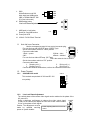
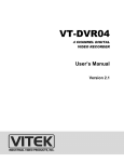
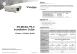
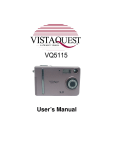
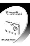
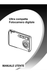
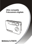
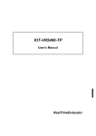
VTC-C594DN
1/3" Hi-Res Day/Night Color CCD Camera
INSTRUCTION MANUAL
Warning: To prevent fire or electric shock hazard, do not expose
the appliance to rain or moisture
1. General
This color video camera employs a 1/3” SONY solid-state, charge coupled
imaging device, and is equipped with a newly developed DSP (Digital Signal
Processor) for video signal processing to provide high color fidelity and a
sharp, stable picture.
2. Features
1. Accepts IR illumination for surveillance in total darkness. Delivers color
images in daylight and automatically switches to black-white images at
night.
2. 420 lines of horizontal resolution and high quality video utilizing digital
processing
3. 0.015lux (@ F0.75) Minimum illumination and signal-to-noise ratio of 48 dB
is achieved by employing a highly sensitive image sensor with micro lenses
and low noise circuit design.
4. High quality picture –A digital signal processor performs digital horizontal
and vertical aperture enhancement to produce a high quality picture.
5. A newly developed intelligent wide range Auto Tracing White Balance (ATW)
that automatically adjusts the tone according to the color temperature of the
light source.
6. Smart digital control Auto BLC, the combination of Histogram equalizer and
Central windows weighting BLC functions ensure for use against any
unusual lighting conditions.
7. Advanced Auto Exposure System for both fixed iris and auto iris lenses
controls the amount of light to ensure optimum video signal.
8. Internal or Line-lock external sync.
To prevent electric shock, do not remove screws or covers.
There are no user serviceable parts inside.
Contact a qualified service person if necessary.
3. Name of Parts and Functions
VTC-C594DN
A
L
I
K
B
M
C
D
H
N
Q
J
G
A. C (CS) mount adapter
F
E
B. Flange focal distance adjustment-If back focus adjustment is necessary, unscrew
the flange back lock screw; optimize the focus by turning this ring.
C. Mounting screw hole
Standard photographic pan-head screw size (1/4” – 20)
D. Flange focal lock screw
E. Auto iris lens connector (MINI JACK)
See 3.1 (Auto-iris connector)
F. Video/DC Auto-Iris Lens Selector.
DC
VIDEO
VIDEO---For VIDEO Drive Lens
DC------- For DC or D/D Direct Drive Lens
G. DC lever Adjuster (VR)
For DC D/D auto iris lens drive level adjustment for obtaining correct exposure to
light.
H. Video output terminal (BNC)
This connector is used to connect to the VIDEO IN connector of a monitor or
processor.
I.
ME
AE
Auto Exposure Mode SW
Manual Exposure SW
FL
FLOFF
AES Low Mode SW
Manual Shutter speed select SW
BLCOFF
Auto Backlight ON/OFF SW BLC
AUTO IRIS
CCD-I
Auto Iris Mode SW
AI SHUT
Auto iris +Shutter Mode SW NORM
Pk
Av
AE Convergence (Av. / Pk )
Manual Gain SW for ME Mode
SUPERAGC
NAGC
AGC Max / Super SW
? =1
? =.45
GAMMA (.45 / 1) SW
0
1
FL=FLICKERLESS, CCD-I=CCD-IRIS, AI SHUT = AUTO IRIS + SHUTTER
SPEED, Av = AVERAGE, Pk = PEAK, AGC=30dB, SUPER=36dB.
J.
SW2
White Balance mode SW
Add. detail see AWB section
VBS in 75OHM ON/OFF SW
(For Gen-lock model)
K. MWB adjust button
WB1
WB2
WB3
NC
Line-lock Phase Adjustment
L.
AWB push to lock button
Detail pls. See AWB section
M. Power pilot LED
PTL
N. AC24V / DC12V Block Terminal
1.1
Auto Iris Lens Connector
Use the accompanying auto iris lens control connector plug.
For auto iris lens with built-in EE amp. (VIDEO Type)
Set the lens selector switch to ”Video” position.
1
Connector cable leads
2
1.Red---- power
3.White-- video
2.NC
4.Black-- shielded
For auto iris lens without EE amp. (DC Type)
This is the external view of camera
Set the lens selector switch to “DC” position.
Connector cable leads
1. Damping coil (-)
3. Driving coil (+)
2. Damping coil (+)
4. Driving coil (-)
Connect the leads as shown above; refer to the instructions of the lens.
1.2
1.2.1
Power Terminal
AC24V/DC12V model
non-polarity
DC12V
This terminal accepts both AC 24V and DC 12V
~DC2
G
NC
1.2.2
Line-Lock Phase Adjustment
The vertical phase of the camera video signal can be matched to the phase of the
AC power line.
Using a dual-trace oscilloscope to observe the video output signal
PHASE
(V-rate) of the camera and adjust the Line-lock Phase control buttons
to line up the phase of both signals
Caution: The adjustment must be
made by qualified servicing Phase adjusting Buttons for Line-lock
model.
person or system installer.
3
4
4. White Balance Adjustment
Mode selection for each operation as shown in the table below:
WB Control Mode Selection Table
Mode
ATW
AWB(conventional)
PUSH TO LOCK
MWB
INDOOR
FLUORESCENT
FL 2
OUTDOOR
SW2
WB1
0
0
0
0
1
1
1
1
WB2
0
1
1
0
0
0
1
1
1.3 ATW mode---- Set the Dip SW. WB1, WB2, WB3 to
“0” position,
WB3
0
0
1
1
0
1
0
1
0
In this mode, the color temperature is monitoring
continuously, and the white balance is set automatically by
internal microcontroller.
The operating color temperature range is from 2500°K to
9500°K (approximately.)
This mode is the default setting when shipped from the
factory.
1.4
WB1
WB2
WB3
AWB mode—Conventional auto white balance
WB1
WB1=0, WB2=1 , WB3=1
WB2
WB3
1.5 Push to lock mode --- set the Dip SW. WB1=0,
WB2=1 , WB3=1
If the camera is used in conditions as described below.
The subject is illuminated by several different light sources
A sodium lamp, mercury vapors lamp or special effects lamp is
used.
o The subject has a single color, like blue, red, etc.
o A picture with proper tone may not be obtained, in such case
please adjust the tone while observing the picture on a color monitor
o
o
1.6 After setting the dip switches into “push to lock” mode,
point the camera at a white object and bring it into focus.
1.6.1
PTL
Point at the subject to fulfill the TV screen.
Use a light to illuminate the subject.
Press the set button, to optimize the picture color.
1.7 Manual mode white balance - set the Dip SW. WB1=0,
WB2=0, WB3=1
WB1
1.7.1
WB2
When the dip SW. setting is set to MWB, use the
up/down SW. to adjust.
1.7.2
Press the up/down key simultaneously back to
1
WB3
WB1
WB2
WB3
preset white balance position.
1.8
Preset mode white balance
0
1
WB1
WB1
WB1
WB1
WB2
WB2
WB2
WB2
WB3
WB3
WB3
WB3
Indoor
3200°k
Outdoor
6300°k
Fluorescent
4200°k
4700°k
5. AE Setting
AE/ME Dip SW= 0 (AE position)
AE MODE CONTROL
MODE
SW1
AE/ME
CCD IRIS MODE (AES)
AE
FLOFF
BLC
CCD-I
CCD IRIS MODE BLC OFF
AE
FLOFF
BLCOFF
CCD-I
AES LOW MODE
AE
FL
BLC
CCD-I
AUTO IRIS MODE
AE
FLOFF
BLC
AUTO IRIS
AUTO IRIS MODE BLC OFF
AE
FLOFF
BLCOFF
AUTO IRIS
1.9
AES Mode(AE/ME=0, CCD-I=0,)
(CCD IRIS mode)
If you are using a fixed or manual iris lens, please select
this mode to control the exposure with the electronic
shutter. The range of the shutter speed is from 1/60 to
1/100,000 sec.
1.10 AES LOW Mode (AE/ME=AE, FLOFF/FL=FL
position)
In order to reduce blurring under low light, in this mode, the
shutter is set from 1/100 sec. NTSC to 100,000 sec
continuously.
1.11 Auto Iris Mode (AE/ME=AE, CCD-I / AUTO
IRIS = CCD-I position)
If you are using an auto iris lens, please select this
mode, In this mode, the shutter speed is fixed to 1/60 sec.
NTSC.
1.12 Auto iris With Shutter speed Mode
(AE/ME=AE, AI SHUT at “1” position)
This mode has same function as auto iris mode, but
with selectable shutter speed by user.
This mode is very useful for the application that allows
capturing of fast moving objects with higher shutter speed
and adequate depth of field. Please refer to table 1 in the
ME section for shutter speed selection.
AE
FLOFF
BLC
CCD-I
NORM
Av
NAGC
? =.45
ME
FL
BLCOFF
AUTO IRIS
AI SHUT
Pk
SUPERAGC
? =1
0
AE
FLOFF
BLC
CCD-I
NORM
Av
NAGC
? =.45
1
ME
FL
BLCOFF
AUTO IRIS
AI SHUT
Pk
SUPERAGC
? =1
0
AE
FLOFF
BLC
C-IRIS
NROM
Av
AGC
? =.45
1
ME
FL
BLCOFF
A-IRIS
AI SHUT
Pk
SUPER
? =1
0
AE
FLOFF
BLC
CCD-I
NORM
Av
NAGC
? =.45
1
ME
FL
BLCOFF
AUTO IRIS
AI SHUT
Pk
SUPERAGC
? =1
6. Me Setting
AE/ME DIP SW = ME
0
Dip SW “FL”, “BLC”, and “CCD-I” for
setting the shutter speed from 1/60 to
1/10,000 sec. In addition, the GAIN
can be selected from 0 to 18 dB by DIP
SW of “Av/Pk” and
“NAGC/SUPERAGC”.
For details, please refer to table 1 for
Shutter speed and table 2 for Gain
setting.
Shutter speed (table 1)
SHUTTER SPEED
1/60 SEC
1/100 SEC
1/250 SEC
1/500 SEC
1/1000 SEC
1/2000 SEC
1/4000 SEC
1/10000 SEC
Gain control (Table 2)
GAIN
0 dB
6 dB
12dB
18dB
AE/ME
ME
ME
ME
ME
ME
ME
ME
ME
ME
FL
BLCOFF
AUTO IRIS
AI SHUT
Pk
SUPERAGC
? =1
AE
FLOFF
BLC
CCD-I
NORM
Av
NAGC
? =.45
FLOFF
FL
FLOFF
FL
FLOFF
FL
FLOFF
FL
AE/ME
ME
ME
ME
ME
BLC
BLC
BLCOFF
BLC OFF
BLC
BLC
BLC OFF
BLC OFF
Av
Pk
Av
Pk
SHUTTER
SPEED
GAIN
SETTIN
CCD-I
CCD-I
CCD-I
CCD-I
AUTO IRIS
AUTO IRIS
AUTO IRIS
AUTO IRIS
NAGC
NAGC
SUPERAGC
SUPERAGC
7. Auto Back-light Compensation
BLC ON
BLC
BLC OFF
BLCOFF
BLC
BLCOFF
This intelligent auto BLC is a newly developed digital light level control system, it is
activated automatically by screen histogram (contrast) and 225 area window
weighting integration to control iris gain and white balance simultaneously, so that
the optimum object light level can be achieved.
1.13 Central Window Weighted average Backlight compensation
This method is best used in cases where the main subject is fixed within the
screen.
1.14 Histogram Backlight compensation
This method is best used in cases where the main subject moves about within
the screen image.
1.15 The combination of two types of Backlight makes it easier to arrange
the compensation operation to match the imaging conditions and installation
location.
Note: Compensation may be insufficient under extremely bright conditions.
8. Infra-Red projection
In a low light environment, a standard color camera cannot obtain a clear picture
with an IR illuminator. This camera has been specially designed with the capability
to accept most IR projection, delivering a clear black and white picture under
absolute darkness.
The Infrared wavelength is from 800nm to 1000nm.
The focus may vary slightly with IR wavelength due to lens diffraction to long-wave.
When installing the camera with an IR projector, please check the focus under IR
illumination and normal light conditions, to find an adequate medium focusing
position.
It is recommended to close the lens aperture one or two stops to increase the depth
of field and compensate for the lens diffraction.
9. Specifications
Image device
1/3” interline transfer SONY Super HAD CCD
Signal system
NTSC standard
Picture Elements
537(H) x 505(V) STD
Scanning system
525 lines. 2:1 interlace
Sync system
DC 12V / AC 24V Line-lock
Horizontal resolution
420 TV lines
Minimum illumination
0.015 lux at F0.75 / 0 lux under Infra-red illumination
Infra-red wavelength
From 800nm to 1000nm
Aperture correction
H aperture and V aperture
Gain
Max. Gain 30dB; Super Gain 36 dB
S/N ratio
Better than 48dB
Auto exposure system
4 modes selectable by Dip-switch
AE CCD iris mode
1/60 sec. \ 1/100,000 sec.
AE AES low mode
1/100 sec. \ 1/100,000 sec.
AE Auto iris mode
1/60 sec.
AE Auto iris + shutter
speed mode
1/60 \ 1/10,000 sec.
AE level
Average, Peak selectable
Manual exposure system Shutter: 1/60, 100, 1/250, 1/1,000, 1/2,000, 1/ 4,000,1/10,000 sec. /
Gain: 0,6,12,18dB
Auto iris lens
Accepts Video or DC servo iris lens
ATW
2500°K to 9500°K
AWB
Push To Lock and Conventional AWB
MWB
R Gain, B Gain
FWB
Indoor 3200°K , Fluorescent1 4200°K, Fluorescent2 4700°K, outdoor
6300°K.
Gamma
45 / 1
Backlight compensation
Auto Detect On/off; Histogram plus windows weight BLC
Video output signal
Composite: 1 V p-p at 75 Ohm
Lens mount
C & CS mount
Operating temperature
14°F to 122°F (-10°C to 50°C)
Power source
AC 24V /DC 12V (Non-polarity)
Power consumption
3.5W (DC type) / 5.5W (AC type)
Dimensions (W x H x D)
2.25” x 2.05” x 4.33” (57 x 52 x 110mm)
9970 GLENOAKS BLVD. UNIT B SUN VALLEY, CA 91352
PHONE: 888-VITEK-70 818-771-0300 FAX: 818-771-0400
WWW.VITEKCCTV.COM