1
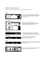
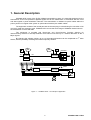
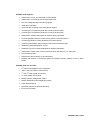
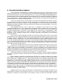
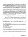
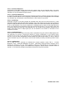
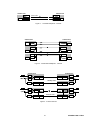
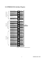
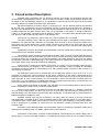
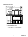
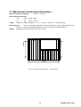
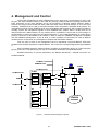
PCM30U-OCH
Protection Signal and Command
Transmission System
Brief Description
TTC TELEKOMUNIKACE, s.r.o.
Třebohostická 5, 100 43 Praha 10
Czech Republic
tel.: +420 234 052 289 (234 052 287)
fax: +420 257 210 385
Doc.No. C405S970.950.14.N02
© 2002
Subject to change without notice
PCM30U Transmission System
PCM30U is a common designation of the following PCM transmission systems:
PCM30U
1st and 2nd order flexible multiplex designed for universal
use in public or private networks, implementing all standard
voice and data interface types, 4x2 Mbps (2x2 Mbps 2x8
Mbps) Cross-Connect
PCM30U-OCH
1st and 2nd order multiplex designed for the
transmission of commands and signals of all commonly
used EHV protection types and other voice and data
signals in the power distribution network
PCM30U-PW
Multiplex designed for one power unit (transmision of
commands, comparative protection, phase timing) with
optional interface (2 Mbps, data up to 64 kbps, modem)
PCM30U-ROK
Broadcast codec for the transmission of two
stereo channels in the 2 Mbps stream or (with
MPEGII) via 256 kbps data circuit
APS
Automatic switch used to transmit external 2 Mbps stream
via two paths, with the higher quality signal being chosen by
the receiving side
MT1
HDB3 metallic line link suitable for long hauls and for cables
with intense interference (typically for railway)
1. General Description
PCM30U-OCH is part of the E1-E2 PCM30U transmission system. It is especially designed for the
transmission of EHV line protection digitized signals and for the transmission of commands but also voice
and data signals in power distribution networks. The transmission is realized via optical cables within the
primary stream of a higher-order system or (with external modem) via metallic cables.
The equipment consists of the central part and the channel plug-in units allowing for connection of all
commonly used line protection types. PCM30U-OCH can use the whole range of PCM30U channel units for
the transmission of voice and data.
The equipment is provided with Drop-Insert and Cross-Connect functions allowing for
interconnecting channels of 64 kbps between local channel units and up to 4 external directions of the 2
Mbps signals.
By changing the software variant, up to 2 of the external directions can be multiplexed to 2nd order
stream, with the possibility of adding other external primary streams.
LAN
E1
E1
LAN
E1
E1
30U-OCH
protection
E2
E1
30U-OCH
50Hz
bin.
dig.
protection
phase
30U-OCH
30U-OCH
command
synchro
Figure 1 – 1 PCM30U-OCH – an Example of Application
1
C405S970.950.14.N02
PCM30U-OCH supports:
•
transmission of up to 20 commands or binary states
•
transmission of commands over 64 kbps data circuit
•
time and voltage filtering of interfering signals
•
cable failure indication
•
command time recording in the management system
•
connecting 4-w comparative protection circuits by 50 Hz signal
•
connecting 2-w comparative protection circuits by 50 Hz signal
•
transmission of phase information for phase-matching purposes
•
connecting digital protection circuits having optical or electric interface
•
connecting protection circuits generating voice band signals
•
connecting subscribers and exchanges using all usual interface types
•
establishing internal dispatcher circuits
•
establishing circuits for external dispatcher analogue equipment
•
transmission of data of any common interface types and rates of up to 1024 kbps
•
interconnecting LANs
•
transmission path protection or full redundancy
•
separate transmission of protection signals and external primary streams in the 2nd order
stream
PCM30U-OCH also includes:
•
2nd order PCM integrated in the equipment
•
4xE1 or 2xE1 and 2xE2 Cross-Connect
•
1st and 2nd order optical line terminal
•
1st order metallic line terminal
•
DORIS network management system
•
DORIS SERVICE local management system
•
higher EMI resistance
•
protection against unauthorized handling
•
ETSI rack mountable
2
C405S970.950.14.N02
2. Functional Description
The central portion of PCM30U-OCH comprises NP106 power supply unit, CJAB central unit and JR
optional HF interface units. The remaining part of the equipment accommodates channel plug-in units to
connect external devices. The core of the equipment is a 1st order PCM multiplexer with integrated DropInsert and Cross-Connect functions, placed on the CJAB central unit. Up to thirty digitized protection or
command signals, voice and data signals (64 kbps channels) from local channel units may be multiplexed
into a 2 Mbps stream. Cross-Connect matrix allows for interconnecting of 64 kbps channels between local
channel units and up to 4 external 2 Mbps directions.
Two of the external directions are terminated on the CJAB unit by RM1 balanced interface, the other
two directions may be used in connection with the JR interface unit. Modularity of the JR unit makes it
possible to build up the following variants: a variant supporting the 3rd and 4th (bal./unbal.) RM1 interface
(designated as JRM); combination of the RM1 interface and the optical line terminal (JRMO); or a set of two
optical line terminals (JROO).
After upgrading the FW in JRO or JROO unit, it is possible to connect one or two 2nd order
multiplexers placed on the unit, thus creating various operational variants. Among the 2nd order contributory
streams there is always the 1st order signal of the local multiplexer, the other three contributory streams may
be external (JRMO variant - a terminal 2nd order multiplexer). The JROO variant - an intermediate 2nd order
multiplexer - supports the Drop-Insert of 64 kbps channels from a chosen 2 Mbps contributory stream, the
terminating of two contributory streams from a selected direction(s) and transiting of the remaining
contributory streams.
Apart from the central multiplexer part, there are special and standard channel units. They are RO3
and ROR units for 50 Hz signal transmission, DZP unit for binary state transmission, and DO1 and FX units
for optical connection of digital protection circuits. Standard telephone units of the PCM30U system are used
to establish "hot line" connection or to connect distant subscribers (LB, UII16K, UI16K), interconnect 2-wire
or 4-wire exchanges (EM2P, EM4P), interconnect 3-wire exchanges (KPR2, PKR2), establish an internal
(UT) or an external (DIK) dispatcher circuit. Data units offer the whole range of broadly used synchronous
and asynchronous transmission rates from 50 Bd to 1024 kbps using standard types of data interfaces (PDK,
DO4, DO5, S64, P64, RK, DV24, DX21).
The RO3 unit is designed for connection of line comparative protections that on the connective path
communicate by the 50 Hz sine signal with 4-wire interface (such as S 103B, S 105 – ZPA Trutnov, DLN 910
- ABB). Accuracy and minimal delay of transmission on a unit for processing of two bi-directional 50 Hz
signals secures sampling by 16 kHz frequency. The minimal phase deviation allows for using the unit also for
the phase transmission. Doubled sampling frequency means that each signal uses, in addition to the KIn
channel interval determined by its address (unit position), the KIn+16 channel interval.
Technically, the ROR unit is derived from the RO3 unit. In addition it contains a special complement
allowing for co-operation of the unit with DZL and DFL comparative protections' 2-wire interface, produced in
the USSR.
Binary statuses transmission is performed by the DZP unit, enabling, besides the command
transmission, also interconnection of distance and sheath protections of EHV line with a relay output contact
(such as RELZ 100 – SIEMENS, REL 511 - ABB). The unit contains four bi-directional channels with a high
safety level. The four channels can be inserted optionally into one or two channel intervals. The unit is
equipped with communication path failure signaling, failure indication of receive and transmit cables, level
filtering of interfering signals and adjustable time digital filtering. The exact time of the command transmitting
is registered in the central part of the equipment and recorded by the management system in its database.
Less complex then DZP is unit PBS with ability to transfer 16 commands inserted into one 64 kbps channel.
Opposite of DZP it doesn’t check for cable defect and the transmission time is a little extended. Unit is
designed to operate also stand-alone in 1U rack, with optionally interfaces (2 Mbps, data channels 64 kbps,
38.4 kbps, 19.2 kbps, 9.6 kbps, modem).
Digital protections with mutual communication in the data channel of 19.2 kbps or 64 kbps can use
standard electric interface of DO4 (RS232) or DO5 (X.21, V.35) units. As regards resistance against outside
interference, connection over optical fibre is more suitable. The DO1 unit with two transmission channels
3
C405S970.950.14.N02
with optical interface is designed for the connection of the 7SD511, 512 (SIEMENS) comparative protections.
The ABB REL316 and REL551 digital protections in optical interconnection use transmission of 64 kbps
channel in a non-standardized frame of the 2 Mbps signal. The FX unit has been designed to ensure
connection to this optical interface having one optical interface; it inserts selected data into one 64 kbps
channel and transmits their validation over the other one.
Line protection circuits communicating in 0.3 – 3.4 kHz voice band can use standard channel units
for the transmission of two telephone channels, the EM4P and EM2P units are used for 4-wire and 2-wire
transmissions, respectively. These units can also be used for the transmission of other voice band signals,
such as those of modems or voice-frequency carrier telegraphy.
DORIS 2000 NET software, the management system of PCM30U-OCH equipment, is a universal
management system designed for all transmission systems manufactured by TTC. In the network of mutually
connected PCM30U-OCH / PCM30U stations the management channel is transmitted in the S4 service bit of
the KI0 channel interval. The management channel is in every PCM30U-OCH equipment terminated by the
"M" interface that, within one locality, enables management interconnection of those PCM30U / PCM30UOCH devices not being interconnected by 2 Mbps streams. Anywhere in the network is it possible to connect
the RJ control unit for the controlling of max. 64 network elements, represented always by a CJAB unit, to
the "M" interface. The DORIS management system is compatible also with the former version of central units
using the TJ telemetric units. The RJ unit as the "M" interface/"Q" interface converter mediates connection to
the PC serial port. The DORIS SERVICE program enables local management of one PCM30U-OCH
equipment, the DORIS 2000 NET network management of up to 32 local RJ control units and (theoretically)
up to 254 local and remote RJ units per one DORIS interface.
As for the power distributing networks, the producer recommends to use equipment only in the
terminal operation between two points (for transmission of protection commands and signals). Transmission
reliability can be increased by doubling the transmission path between PCM30U-OCH stations or by the
redundant transmission over two parallel sessions.
From the point of view of management, network synchronization and other telecommunication
channels transmission, it is suitable to connect equipment to transmission networks of various structures,
using different external directions of the 1st and 2nd order signals so that a failure in an adjacent network does
not endanger the basic transmission of protection commands or signals.
The mechanical structure used with guaranteed EMI resistance as well as circuit solution enable
faultless operation even in strong interference environment. High reliability is also ensured by temperature
ageing, seasoning, and proper testing of each unit in manufacturing. The equipment manufacturer / supplier
offers comprehensive services – engineering consultancy, projecting, installation, warranty and postwarranty servicing.
2.1. Operating Modes
The CJAB unit is supplied with optional FW that defines the plug-in unit operating mode. It also determines
various operational types of PCM30U-OCH, PCM30U or APS equipment. Following types are available:
TPR 1 – switch of streams
TPR 2 – terminal multiplexer, see figure 2 - 1
TPR 3 – redundant multiplexer, see figure 2 - 2
TPR 4 – intermediate multiplexer
TPR 5 – path back-up, see figure 2 - 3
TPR 6 – flexible multiplexer
TPR 1 – Switch of Streams
This type of operation enables transmission of protected E1 external signal in parallel over two separate
transmission paths and choice of a signal from the better quality path by the receiving end.
TPR 2 – Terminal Multiplexer
Basic application that connects channels from the channel units, placed in identical positions of opposite
stations.
4
C405S970.950.14.N02
TPR 3 – Redundant Multiplexer
Transmission of the 2Mbps stream (local signal from channel units) over two separate paths. In the basic
setting the whole stream is doubled but it is also possible to select function using CC which allows for
redundancy of only the selected 64 kbps channels.
TPR 4 – Intermediate Multiplexer
An equipment variant with two external directions enabling termination of selected channels and transiting of
the others. Channel selection can be changed by control system command. The equipment can be included
in a redundant ring, with automatic channel redirection in case of failure of any section.
TPR 5 – Path Backup
Redundant operation of two paths realized with PCM30U-OCH. Both ends are interconnected by a cable
transmitting 2 Mbps signals and PH0 failure message. One of both paths is set as main one (by means of
jumper in CJAB), whereas the other one as redundant. CJAB units in both ends evaluate main path failures
in one or both directions. They inform CJAB units in redundant path by means of PH0 signal about the
failure. All CJAB units then automatically change the channel interconnection in CC to a backup variant that
re-routes the traffic from main path to the redundant one. The number of less important channels may be
limited. Third and/or fourth 2 Mbps signal port can be activated in this variant for connections to the
neighbouring network.
TPR 6 – Flexible Multiplexer
In this variant, the CC functionality can be fully used in equipment having four external 2 Mbps signal ports.
The equipment can be part of transmission networks of various configurations. In one network section
including one RJ control unit one redundant ring can be established into which the CJAB unit is connected
with its „A“ and „B“ ports. Management channel (S4/KI0) can pass through further „C“ and „D“ ports of
another redundant ring of the same network, with the other network part being controlled by another control
unit.
TPR 10 – PCM30U-OCH
FW of CJAB unit that is delivered for PCM30U-OCH includes operation modes TPR 2 – Terminal
Multiplexer, TPR 3 – Redundant Multiplexer and TPR 5 – Path Backup. Required mode of operation can be
selected by switches in the unit. These operation modes are recommended for the transmission of
commands and protection signals via PCM30U-OCH equipment. Should another operation mode be
required, i.e. FW should be changed, the equipment manufacturer should be consulted.
5
C405S970.950.14.N02
PCM30U-OCH
PCM30U-OCH
optical cable
JRO
KJ
JRO
RM1
CJAB
CJAB
KJ
Figure 2 - 1 Terminal Multiplexer - Variants
PCM30U-OCH
KJ
KJ
KJ
PCM30U-OCH
CJAB
CJAB
JRO
JRO
CJAB
CJAB
JROO
JROO
CJAB
CJAB
KJ
KJ
KJ
Figure 2 - 2 Redundant Multiplexer - Variants
PCM30U-OCH
PCM30U-OCH
DO1
DZP
DO1
CJAB
JRO
JRO
CJAB
JRO
CJAB
DZP
standby mode
DZP
CJAB
JRO
DO1
DZP
DZP
DO1
CJAB
JRO
JRO
CJAB
JRO
CJAB
DZP
failure at main
DZP
CJAB
JRO
path
DZP
Figure 2 - 3 Path Protection
6
C405S970.950.14.N02
2.2. PCM30U-OCH Interface Plug-Ins
specialized cards
transmission of 4 commands
transmission of 16 commands
phase timing 50 Hz – 2 x
interface DZL – SNS – 2 x
interface REL – 1 x
optical interface dig. protections - 2 x
ETHERNET 10 Mbps – 1x
data cards
Up to 38,4/64 kbps async/sync X.21 – 2x
G.703 codirection – 2x
PBS
1x 64 kbps
RO3
4x 64 kbps
ROR
4x 64 kbps
FX
2x 64 kbps
DO1
2x 64 kbps
1-30x 64 kbps
DO4
2x 64 kbps
DO5
2x 64 kbps
P64
2x 64 kbps
S64
2x 64 kbps
64 kbps RS232 RS 422 – 2x
DV24
2x 64 kbps
64 kbps X.21 V.36 RS485 – 2x
DX21
2x 64 kbps
128 - 1024 kbps X.21- 1x
RK
telephone, modem – 2x
subscriber interface – 2x
voice cards
2x 64 kbps
DTE
up to 38,4/64 kbps async/sync RS232 – 2x
G.703 contradirection – 2x
DZP
UII16K
2 Mbps
2-16x 64 kbps
2x 64 kbps
UI16K
2x 64 kbps
exchange E+M 2w – 2x
EM2
2x 64 kbps
exchange E+M 4w – 2x
EM4
dispatcher’s telephone – 1x
UT2
2x 64 kbps
conference channel 2w – 2x
DIK2
2x 64 kbps
conference channel 4w – 2x
DIK4
LB telephone – 2x
MB
2x 64 kbps
incoming relay set SNS – 2x
KPR
2x 64 kbps
outgoing relay set SNS - 2x
PKR
2x 64 kbps
broadcasting codec – 1x stereo
RAD
2-28x 64 kbps
Broadcasting decodec – 1x stereo
RDA
2-28x 64 kbps
2x 64 kbps
2x 64 kbps
Figure 2 - 3 PCM3OU-OCH Interface Plug-Ins
7
C405S970.950.14.N02
3. Construction Description
PCM30U-OCH is supplied in the 19" aluminum subrack of 6U height. An unequipped subrack with
the backplane is designated as 6UOCH. The rack offers five positions for the power interface plug-ins with
the height of 234 mm and depth of 232 mm, nine positions for channel units 100 mm high and 160 mm deep
and three positions for central units of the same dimensions.
Mechanical assembly is shown in Figure 4-1 and Figure 4-2. The five leftmost positions are intended
for the DZP units. Alternatively, the first four positions may be occupied by RO3 or ROR units. Positions 6
through 14 are designed for DO1 and FX units with optical interfaces for digital protection or for the standard
PCM30U telephone and data channel units. If RJ unit is employed in the system, it should be placed in
position 14 and internally connected to the M interface. Position 15 accommodates NP106 power supply
unit, position CJAB central unit and position 17 JR interface unit.
As there are 14 positions for channel units only, channel position No. 9 is omitted.
Two RM1 interfaces of the CJAB unit are accessible from the back on CANON9M connectors at the
backplane. The other two RM1 interfaces are accessible from the front on RJ45 connectors located at the
front panel of the JRM interface unit. FC/PC optical connectors are located on the front panel of the JRO
(JROO) unit and also on the front panel of FX channel unit, while DO1 unit is furnished with SMA optical
connectors.
CANON15M connector at the back of the backplane is used for mutual interconnection of two pieces
of equipment in fully redundant operation.
The cabling of power interfaces is terminated at the back. Each conductor may be easily and quickly
mounted using screw terminals (screwable along the center line of the conductors). After fitting the terminals
to external cabling, the conductors run through the passage in the back panel and connect to the mating
counterparts of the DZP or RO3/ROR plug-in. The same procedure is applied when mounting the conductors
of the alarm relays using a terminal located at the backplane.
Channel plug-in outlets are accessible from behind, by means of two horizontally positioned highdensity connectors at the backplane. The connectors have extended contacts enabling an alternative
connection of external cabling by wire-wrapping or by fitting another female connector to the contacts of a
channel plug-in connector.
For feeding the system from an external DC power supply with voltage of 48 V (40 V to 72 V), it is
necessary to connect the faston-connectors of the power conductors to the mating counterparts at the
backplane. The backplane also carries fuses, accessible from the front after removing a panel at the subrack
upper right part. In case of mains feeding, it is recommended to use an external power converter (220 VAC
to 48 VDC / 1 A). It is supplied by TTC MARCONI and may be fixed to the back cover or to the DIN strip. It is
also recommended to back up the mains voltage by a battery.
All the cabling runs through a passage in the split back cover, with cables fixed to a vertical division
panel. The passage is sealed with a conductive rubber gasket.
External synchronization is possible by means of 2.048 MHz signal with V.11 interface, arriving at
the pins of the CJAB module. The pins may serve as an input (when synchronizing the equipment by an
external signal) or an output (when synchronizing other equipment). To set the mode of synchronization the
DORIS management software is used.
Standard channel units may be connected in two ways, either by means of common connectors
(only applicable in non-data cards) or using a separate cable for each channel position. For the data cards, it
is possible to order output cables card-to-Canon-connector for each card separately. If the "path protection"
mode is employed it is necessary to interconnect the two subracks mutually protecting each other with
427K487 cable.
At the back of the backplane there are several pairs of pins for the setting of operation modes of the
subrack and of individual cards. For details, please refer to User's Manual.
Construction of the system conforms to EMC standards. The equipment has modern design with a
logical layout of controls and LED indicators. A lockable power supply switch at the front panel prevents
8
C405S970.950.14.N02
JR
CJAB
NP106
RJ KJ15
UII16K KJ14
DAT KJ13
KJ12
KJ11
KJ10
KJ8
KJ7
KJ6
DZP
RO3 ROR DZP
RO3 ROR DZP
RO3 ROR DZP
RO3 ROR DZP
unauthorized access. The system has a socket to connect a telephone set and supports hot line calls if
UII16K module is used and placed in position 14.
NP106 and CJAB – modules required for the system to be operational
JR – Interface Module – optionally 2 Mbit/s or 8 Mbit/s
KJ6 to KJ15 – optional PCM30U channel modules
4 - 1 PCM30U-OCH – Front View - a Completely Equipped System
9
C405S970.950.14.N02
3.1. Mechanical Construction Parameters
Mounting flange hole spacing
465mm x 190.5mm.
Basic subrack dimensions:
Height
type
width
height depth
6U
480
265.9
242 mm
is given in U height modules (a * U = a * 44.45 mm – 0.8 mm; a = module number)
Rack mounting:
fix by screwing (M5 to M8) into holes in the ETSI rack in the mounting flanges of 19"
distance. In order to mount the equipment in a 21" rack, use two 1" reduction pieces.
(depends on number of plug-in units): 5 to 15 kgs.
190.5 mm
190.5 mm
Weight
465 mm
Figure 4 - 2 Mechanical Construction – 6OCH Subrack
10
C405S970.950.14.N02
4. Management and Control
Control and management of each PCM30U-OCH unit is ensured by circuits located on their CJAB
plug-ins. The LED indicators located on the CJAB and JR front panels provide the operating personnel with
basic information on the unit's operation and on the functioning of adjacent network sections. Within a
subrack, the plug-ins communicate with their CJAB units either via the K serial interface or via IP bus (time
multiplex). S4/NOTFAS bit is used to transmit information within a PCM30U / PCM30U-OCH network. The
management channel of each PCM30U-OCH unit is terminated at the M interface, which makes it possible to
mutually connect the management signals of those PCM30U-OCH systems within a locality that are not
interconnected via 2 Mbps streams. At any network point it is possible to connect the RJ control plug-in to
the M interface in order to manage up to 64 network elements, i.e. the CJABs. Beside that, RJ control plug-in
performs conversion of M interface to Q interface in order to make the PCM30U management compatible
with the DPS2000 management. At the Q level, it is then possible to interconnect RJ units of different
localities and to connect them to a management computer with the DORIS software.
From the point of view of the management, each RJ represents a physical address, while each
PCM30U-OCH subrack represents a logical address. The control unit is always assigned the logical address
0.
Also a PCM30U subrack in classical version containing TL03 telemetric plug-in or a SMJ card (loop
plug-in) or the OZ1 / OZ2 optical plug-ins may be connected to M interface as logical addresses.
Detailed instructions for use are described in the DORIS SW Manual – General Part and in the
PCM30U Manual.
PCM30U
PCM30U-OCH
PCM30U-OCH
CJAB
PCM30U-OCH
PCM30U
DORIS
F
S4/
KI0
UART 0
V.11
M
FRAME
RS232
LM
UART 1
XILINX
RJ
Q
E1
M
PCM30U-OCH
K
IP
JR
UART
DZP
PCM30U
network
UART
DIK
XILINX
Figure 5 - 1 PCM30U-OCH Management System
11
C405S970.950.14.N02
5. Technical Specifications
5.1. Electromagnetic Compatibility (EMC)
5.1.1.
Immunity against Electrostatic Impulse
ČSN EN 61000-4-2:1997
Parameters of Generated Impulse
Rise Time of Discharge
0.7-1 ns
Polarity
positive, negative
The equipment meets the specification requirements.
5.1.2.
Immunity against HF Electromagnetic Field
ČSN EN 61000-4-3:1997
Parameters of Generated Impulse
Frequency Band
80 MHz – 1000 MHz, antenna BTA-L
Scanning Rate
1.5 x 10⁻³ dec/sec
Modulation
80% AM 1 kHz
Intensity of Electric Field
10 V/m
Polarisation
horizontal, vertical
Distance between the Antenna and the Equipment Tested 1m
The equipment meets the specification requirements.
5.1.3.
Immunity against Impulse Burst
ČSN EN 61000-4-4:1997
Parameters of Generated Impulse
Rise Time of an Impulse
5ns
Impulse Duration (50% value) 50ns
Burst Duration
15ms
Burst Period
300ms
Polarity
positive, negative
Test Duration
60s
The equipment meets the specification requirements.
5.1.4.
Immunity against Voltage Impact Wave
(ČSN EN 61000-4-5:1997)
Parameters of Generated Impulse
Amplitude
0.5, 1 kV
Shape
10-700 µs series of 5 impacts
Polarity
positive, negative
12
C405S970.950.14.N02
Generator Output Impedance
40 ohms
The equipment meets the specification requirements.
5.1.5.
Immunity against Interference along Line, Induced by HF Field
(ČSN EN 61000-4-6:1997)
Parameters of Generated Impulse
Frequency Band
Scanning Rate
Modulation
Level of Test Field
150 kHz – 80 MHz
1.5 x 10⁻³ dec/sec
80% AM 1 kHz
10V
The equipment meets the specification requirements.
5.1.6.
Radio Interference (ČSN EN 55022B )
Measurement Parameters
Measured at the Distance of
10m
Frequency Band
30 – 1000 MHz
Frequency Band
100 – 200 MHz
Frequency Band
150 kHz – 30 MHz
The equipment meets the specification requirements.
5.1.7.
Mechanical Tolerance and Climatic Conditions
5.1.7.1.
Climatic Conditions
The equipment is designed for the stationary indoor use in dust-free rooms having fire-resistant
construction, free of chemical vapours, having controlled climatic conditions and fire-resistant or flameproof
floor.
In accordance with OEG 38 3020 standard "Automated Systems of Dispatcher Management of
Electricity and Warm Distribution Networks" and IEC 57, the equipment meets the requirements of
environmental class B4:
5.1.8.
Operational Temperature
5°C to 55°C
Max. Rate of Temperature Change
20°C/hr.
Rel. Air Humidity
5 to 95 %
Environment Dustiness
28 g/m3
Space Requirements
Equipment dimensions are 483 mm x 266 mm x 302 mm
5.1.9.
Environmental Requirements
- follow from the point 5.2.1
13
C405S970.950.14.N02
5.1.10. Requirements Concerning Power Supply Voltage
♦
Power Consumption
The consumption differs in dependence on the plug-in unit composition in the PCM30U-OCH
subrack. If the subrack is fully equipped with CJAB, NP106, 3x DZP, RO3 units and all the command relays
are powered and both LF RO3 channels are driven the consumption is max. 20 W then. If RO3 unit is not
used and command relays are not powered then the power consumption is 10.8 W. Eight command relays
drain approx. + 2 W and both LF channels of RO3 approx. + 7 W.
♦
Tolerance
Nominal power supply voltage is 48 or 60 VDC -15% +20%. Considering tolerances, the power
supply voltage may vary between 40 and 72 VDC. Even short-term surpassing the upper limit results in a
destructive reaction of input protection circuits. Service intervention is required then. Redundant power
supply units that demonstrate a short-term overshoot bigger than 72 V when switched to battery-powered
mode cannot be used for PCM30U-OCH supplying.
♦
Circuit Protection
Supply line 48 VDC or 60 VDC is protected by a 4 ADC circuit breaker. In the block input a glass
tube fuse is used rated 3.15A / F (flink). An overvoltage accumulation circuit is located behind this fuse
having a limited temperature capacity followed by an input of plug-in unit NP106.
♦
Maintenance
During warranty period the equipment is maintained by personnel trained for PCM30U-OCH
attendance and maintenance and having obtained a service licence valid for the appropriate time period.
After-warranty attendance and maintenance can be performed by trained technicians at customer's
discretion (training by TTC / TTC MARCONI personnel is recommended).
5.1.11. Packing, Transport and Storing
Each device is packed individually in a box with fillers. The box is provided with a label carrying
appropriate transport marking.
Packed equipment can be transported by train, or by a covered car at the same temperature and
humidity conditions as at store. The equipment can be stored in ventilated rooms. Environment temperature
may vary between -20 and +55 oC without abrupt changes, at relative humidity of max. 85 %. The
environment must be dust-free, free of chemical influence and vibrations.
5.2. Working Safety
5.2.1. General Provisions (Valid for the Czech Republic)
♦
♦
♦
Regular attendance of the equipment may be exercised by an "instructed person" in the sense
of ČSN 34 3100 (Safety Regulations for Attendance and Work on Electrical Appliances) standard
after having acquainted himself with the equipment technical documentation.
Repairs of equipment may be exercised by a "knowing person" having specialized electric
education according to ČÚBP 50/1978 standard.
The equipment is protected against lightning in buildings and thus the requirements of
ČSN 34 1390 standard are met.
5.2.2. General Provisions (Valid for other Countries)
♦
♦
♦
Regular attendance of the equipment may be exercised by a person qualified for attendance of
electric appliances up to 1000 VDC in the sense of valid local standards.
Repairs of equipment may be exercised by a person qualified to working on electric appliances
up to 1000 VDC in the sense of valid local standards.
The equipment is protected against lightning in buildings and thus those parts of standards
can be applied valid for working on equipment protected against atmospheric discharges.
14
C405S970.950.14.N02
5.2.3. Protective Aids
The equipment is designed not to require any special protective aids under normal operation
conditions. When working on optical units or optical fibres where signals generated by laser transmitters can
occur it is obligatory to have the equipment switched off or to use protective polarisation glasses. The works
may not start until the dispatcher determines the date when the equipment may be switched off.
5.2.4. First Aid at Electric Accidents
With regard to the fact that the personnel can get in touch with the low voltage equipment (230 VAC)
they must be informed on principles of first aid at electric accidents.
5.2.5. Protection against Hazardous Contact
The equipment meets the requirements of ČSN EN 60950 A1, A2 standard for devices to be
connected into telecommunication networks.
♦
Safety of operation of PCM30U-OCH units:
Electrical Strength of DZP, RO2:
> 2 kV
Insulation Resistance of DZP, RO2
>50 MOhms
5.2.6. Safety Provisions under Extraordinary Conditions
The equipment is provided with special overvoltage protection means. With regard to the character
of the atmospheric electricity danger the personnel is not allowed to touch metal equipment parts in
thunderstorms.
5.2.7. Fire Protection Measures
New devices will be placed in rooms accommodating existing communication equipment. It is
recommended to provide these rooms with snow fire-extinguishers.
6. Installation, Warranty, Servicing
6.1. Installing and Maintenance Conditions
Prior to installing the equipment, it is necessary to prepare project documentation. For details on
a project, please refer to the Instructions for Use and Maintenance, Chapter 7 – Project and Installation
Guide.
Installing and maintenance works may only be done by trained personnel!!
6.1.1. Switching Off the System
PCM30U-OCH subrack may not be switched off at will. The equipment may only be switched off
with the approval of the dispatcher of the plant or upon a written order. If there is more than one
subrack in the rack, a service engineer or a dispatcher should be present in order to avoid improper
handling.
After switching the PCM30U-OCH rack off, it is necessary to disconnect the operating voltage
(230 VDC) that has been connected via cable conductors to the command relay contacts or to the inputs of
the transmitting opto-couplers.
15
C405S970.950.14.N02
6.1.2. Reset
All the units in a subrack may be initiated by a software command, by pressing the RESET button on
the CJAB unit or by switching the subrack off and on again. All previous settings will be preserved after a
reset except for loops, which will be cancelled.
6.2. Warranty and Servicing Conditions
Warranty and servicing conditions may be regulated either by a special contract or by the general
terms below.
6.2.1. General Servicing Conditions
(applicable if not otherwise agreed upon by a special contract)
♦
Beginning of warranty period
Where equipment is part of a turnkey delivery, warranty period starts on the day on which
construction is handed over to the user. If customer / user requests to operate equipment prior to taking over
the construction, the customer / user shall ask for the warranty to take effect. In such a case, the warranty
period shall last for 24 months following the delivery of equipment. Operation of equipment shall mean full
operation with subscribers. Using equipment for measuring or testing purposes or for training of personnel
shall be without limitation.
Where only the delivery of equipment has been ordered without installation, commissioning etc., the
warranty period shall start on the day of equipment sale.
♦
Handling and servicing equipment during the warranty period
If equipment is used in a power utility network for the transmission of commands and protection
signals over EHV lines, only duly trained and authorized personnel may handle the equipment. Such
personnel may handle or reconfigure the equipment but a warranty service intervention shall only cover
original configurations or individual plug-in units. During the handling of equipment, the rules described in
chapter Operation and Maintenance of Equipment must be observed.
♦
The warranty shall not cover the following:
Defects following from improper handling.
Defects following from inappropriate storing during which instructions described in chapter
Packaging, Transport and Storage have not been observed.
Natural disasters out of control of the manufacturer, such as fire, flood, atmospheric electricity
discharges.
Installation failing to observe rules described in chapter Conditions of Installation, Mounting and
Maintenance.
6.2.2. Software Warranty
To make a claim on software, customer must present the software product including licence
agreement.
The warranty shall not cover service works ordered by the customer that indicate proper function of
the manufacturer's products but indicate failures of any other product not being serviced by TTC MARCONI.
6.2.3. Procedure in Case of a Defective Plug-in Unit
Repair of a plug-in unit shall not be carried out by way of exchanging units. Customer is supposed to
have adequate store of spare parts. Parts manufactured by TTC shall as a rule be repaired within 30 days
from the issuance of "Defective Part(s) Takeover Report". If a plug-in unit proves to be non-repairable,
16
C405S970.950.14.N02
customer shall be invoiced costs of ascertaining the defect and shall be given an offer to buy a new part. In
order to claim a warranty repair, the defective part must be accompanied with a copy of a document proving
that the part is still in the warranty period.
Procedure:
♦
A defect has been ascertained by a TTC MARCONI's service engineer
The service engineer shall propose to take over the defective part for the repair and shall issue a
"Defective Part(s) Takeover Report" to the customer. After thirty days, the customer may pick up the repaired
part in TTC MARCONI's premises or, if the part has not been repaired, claim a new one. If a part is
unrepairable, the customer shall be notified to the telephone contact number stated in the "Defective Part(s)
Takeover Report".
♦
A defect has been localized by a customer's technician who is a holder of the TTC MARCONI's
service licence
The technician shall draw up the "Defective Part(s) Takeover Report" himself, stating his name and
service licence number and shall hand over the defective parts and the relevant documents to the TTC
MARCONI's premises or send them by mail. After the consignment is received by TTC MARCONI, thirty-day
repair period starts.
♦
A defect has been localized by a technician who is not a holder of the TTC MARCONI's service
licence
During the warranty period, such a technician shall be obliged to ask for approval from the TTC
MARCONI Service Department for each individual intervention into the equipment and to consult procedure
of localizing the defect. He shall be sent the form of the "Defective Part(s) Takeover Report" by e-mail or by
fax and he will fill in contact data. Then he shall hand over the defective parts and the relevant documents to
the TTC MARCONI's premises or send them by mail. After the consignment is received by TTC MARCONI,
thirty-day repair period starts. Should a service intervention be made without consulting the Service
Department, warranty repair may not be claimed unless in obvious defects due to workmanship.
6.2.3.1.
♦
♦
♦
Telephone Consultations
TTC MARCONI Service Department shall only provide information necessary for the operation,
maintenance and attendance of equipment serviced by them. They shall not provide information
of commercial or development nature, though they may assist in contacting the responsible
person, as a rule the Head Project Coordinator.
Calls aiming at obtaining details for a service intervention shall be without limitation.
Consultations needed for localization of a defect or for getting acquainted with the service
conditions shall be provided at the expense of the equipment user.
6.2.4. Service Intervention at Customer's Premises
Customer may ask for a service intervention by an engineer of TTC MARCONI Service Department
at his premises. The request may be communicated by phone or by e-mail addressed to Service Department
with confirmation by fax in either case. If not otherwise agreed upon in a service contract, the customer shall
be contacted by phone and service intervention shall take place within the next three working days. An
urgent service intervention may be requested, in which case intervention shall take place immediately, with
extra charge payable even during the warranty period (unless otherwise agreed upon in the service
contract).
17
C405S970.950.14.N02