1
Artwork and Signature File for:
9-500-0276, MNL, M4/PLATINUM SVC
Artwork consists of:
•
REV AUTHORED BY
M. GALL
REV DRAFTED BY
B. MOSES
One hundred eighty-six (186) 8 ½ inch x 11 inch pages.
DATE
10/6/2003
DATE
DANBURY, CT 06810
10/8/2003
TITLE
PROPRIETARY INFORMATION:
The content of this document is the
exclusive property of Lorad and may
not, without prior written permission
of Lorad, be reproduced, copied or
used for any purpose whatsoever.
DOCUMENT NUMBER
MNL, M4/PLATINUM SVC
ARTWORK
AW-00284
SIZE A
REV
004
SHEET 1 OF 1
ENG-0034- T33, Rev. 001
Series
COMP
RESSI
M
C-ARM
C-AR
ON
COMPRESSIO
N
C-A
A Hologic Company
RM
Service Manual
9-500-0276
Service Manual
for M-IV Series Mammography Systems
Second Edition
Part Number 9-500-0276,
Revision 004
This manual applies to M-IV Mammography Systems manufactured after August 2001.
For systems manufactured before August 2001, use part number 9-500-0170.
Service Manual
REVISION HISTORY
REV
Rev 1
Rev 2
DATE
8/22/2001
9/05/2001
Rev 3
Rev 004
11/20/2002
10/6/2003
MODIFICATION
PAGES AFFECTED
ALL
Initial Release of 2nd Edition
Incorporated review comments;
ALL
Revised specifications;
Manual restructuring
Revised specifications; Illustration
1-9; A-7
Clarified specifications
A-7
Service Manual
Service Manual
Table of Contents
Preface
1.0 Using the Service Manual . . . . . . . . . . . . . . . . . . . . . . -xix
1.1 Warnings, Cautions and Notes . . . . . . . . . . . . . . . . . . . . . . . . . -xx
2.0 Acronym List. . . . . . . . . . . . . . . . . . . . . . . . . . . . . . . . -xx
Chapter 1: General Information
1.0 Intended Use. . . . . . . . . . . . . . . . . . . . . . . . . . . . . . . . . 1-1
2.0 Introduction . . . . . . . . . . . . . . . . . . . . . . . . . . . . . . . . . 1-1
3.0 Unit Description . . . . . . . . . . . . . . . . . . . . . . . . . . . . . . 1-1
3.1 Required Tools and Equipment . . . . . . . . . . . . . . . . . . . . . . . . . 1-2
4.0 Safety . . . . . . . . . . . . . . . . . . . . . . . . . . . . . . . . . . . . . . 1-3
4.1 Electrical Safety . . . . . . . . . . . . . . . . . . . . . . . . . . . . . . . . . . . .
4.2 Static Electricity and Magnetic Field Safety . . . . . . . . . . . . . . . .
4.3 Mechanical Safety . . . . . . . . . . . . . . . . . . . . . . . . . . . . . . . . . .
4.4 Radiation Safety . . . . . . . . . . . . . . . . . . . . . . . . . . . . . . . . . . . .
1-3
1-3
1-3
1-4
5.0 Unit Layout . . . . . . . . . . . . . . . . . . . . . . . . . . . . . . . . . . 1-5
5.1 The Operator Console . . . . . . . . . . . . . . . . . . . . . . . . . . . . . . . 1-5
5.2 The Gantry and C-Arm . . . . . . . . . . . . . . . . . . . . . . . . . . . . . . . 1-6
6.0 Compliance Data . . . . . . . . . . . . . . . . . . . . . . . . . . . . . 1-7
6.1 Responsibility Statement . . . . . . . . . . . . . . . . . . . . . . . . . . . . . .
6.2 Compliance Statement . . . . . . . . . . . . . . . . . . . . . . . . . . . . . . .
6.3 Certifiable Components . . . . . . . . . . . . . . . . . . . . . . . . . . . . . .
6.4 Compliance and Identification Label Locations. . . . . . . . . . . . .
1-7
1-7
1-8
1-8
vii
Service Manual
Chapter 2: System Installation
1.0 Unpacking The Unit . . . . . . . . . . . . . . . . . . . . . . . . . . . 2-1
1.1 Receiving Instructions. . . . . . . . . . . . . . . . . . . . . . . . . . . . . . . .
1.2 Un-crating—Gantry . . . . . . . . . . . . . . . . . . . . . . . . . . . . . . . . .
1.3 Un-crating—Operator Console . . . . . . . . . . . . . . . . . . . . . . . . .
1.4 Unpacking—Accessories . . . . . . . . . . . . . . . . . . . . . . . . . . . . .
2-1
2-1
2-2
2-2
2.0 Unit Installation . . . . . . . . . . . . . . . . . . . . . . . . . . . . . . 2-3
2.1 Installation—Gantry . . . . . . . . . . . . . . . . . . . . . . . . . . . . . . . . .
2.2 Installation—Operator Console. . . . . . . . . . . . . . . . . . . . . . . . .
2.3 Installation—Footswitches . . . . . . . . . . . . . . . . . . . . . . . . . . . .
2.4 Installation—Radiation Shield. . . . . . . . . . . . . . . . . . . . . . . . . .
2.5 Installation—Bar Code Reader . . . . . . . . . . . . . . . . . . . . . . . . .
2-3
2-4
2-6
2-7
2-8
3.0 M-IV Interconnections. . . . . . . . . . . . . . . . . . . . . . . . . . 2-9
3.1 Interconnections—Gantry to Console . . . . . . . . . . . . . . . . . . . . 2-9
3.2 Connecting to Power . . . . . . . . . . . . . . . . . . . . . . . . . . . . . . . 2-11
4.0 System Power Up . . . . . . . . . . . . . . . . . . . . . . . . . . . . 2-12
viii
Service Manual
Chapter 3: System Setup
1.0 Switches and Connections . . . . . . . . . . . . . . . . . . . . . . 3-1
1.1 Remote Console Switch Settings . . . . . . . . . . . . . . . . . . . . . . . . 3-1
1.2 Host Microprocessor Board Switch Settings . . . . . . . . . . . . . . . 3-2
2.0 Functional Checks—Mechanical. . . . . . . . . . . . . . . . . . 3-6
2.1 Functional Checks—Compression System. . . . . . . . . . . . . . . . .
2.2 Functional Checks—C-arm Movement System . . . . . . . . . . . . .
2.3 Functional Checks—Collimator Lamp Button . . . . . . . . . . . . . .
2.4 Functional Checks—Collimator Override Switch . . . . . . . . . . .
3-6
3-6
3-7
3-7
3.0 Setting System Defaults . . . . . . . . . . . . . . . . . . . . . . . . . 3-8
3.1 Making Selections / Entering Data. . . . . . . . . . . . . . . . . . . . . .
3.2 The Default Worksheet . . . . . . . . . . . . . . . . . . . . . . . . . . . . . .
3.3 Setting Defaults—Setup Mode Screen . . . . . . . . . . . . . . . . . . .
3.4 Default Settings - Additional Setup Mode Screen . . . . . . . . . .
3-10
3-10
3-13
3-16
4.0 Exposure System Calibration . . . . . . . . . . . . . . . . . . . . 3-21
4.1 Line Regulation Check . . . . . . . . . . . . . . . . . . . . . . . . . . . . . .
4.2 Setting—X-ray Tube Type . . . . . . . . . . . . . . . . . . . . . . . . . . . .
4.3 Tube Bias Adjustment . . . . . . . . . . . . . . . . . . . . . . . . . . . . . . .
4.4 Tube Current (mA) Adjustment . . . . . . . . . . . . . . . . . . . . . . . .
4.5 Tube Voltage Potential (kV) Adjustment . . . . . . . . . . . . . . . . .
3-21
3-21
3-21
3-22
3-24
5.0 Automatic Exposure Control Calibration . . . . . . . . . . . 3-25
5.1 AEC Detector Gain Calibration . . . . . . . . . . . . . . . . . . . . . . . .
5.2 AEC Calibration . . . . . . . . . . . . . . . . . . . . . . . . . . . . . . . . . . .
5.3 Preparation for Compression Thickness Threshold Adjustment
5.4 Reduced Large Spot mA Calibration . . . . . . . . . . . . . . . . . . . .
5.5 Compression Thickness Threshold Adjustment . . . . . . . . . . . .
5.6 HTC Filament Off Time (Auto-kV Calibration) . . . . . . . . . . . .
5.7 Reduced mA Optical Density Offset Calibration . . . . . . . . . . .
3-27
3-27
3-32
3-32
3-32
3-33
3-34
6.0 Download—Calibration Values. . . . . . . . . . . . . . . . . . 3-34
7.0 Final Set Up Checks . . . . . . . . . . . . . . . . . . . . . . . . . . 3-35
7.1 AutoFilm ID Setup . . . . . . . . . . . . . . . . . . . . . . . . . . . . . . . . .
7.2 Exposure Counter Reset . . . . . . . . . . . . . . . . . . . . . . . . . . . . .
7.3 C-arm Rotation Speed Check . . . . . . . . . . . . . . . . . . . . . . . . .
7.4 Setting—Compression Release Distance . . . . . . . . . . . . . . . . .
7.5 Setting—Auto-Filter kV Threshold and Offset . . . . . . . . . . . . .
3-35
3-35
3-35
3-36
3-36
ix
Service Manual
Chapter 4: Performance/Compliance Checks and Adjustment Procedures
1.0 Introduction . . . . . . . . . . . . . . . . . . . . . . . . . . . . . . . . . 4-1
2.0 X-ray System Performance. . . . . . . . . . . . . . . . . . . . . . . 4-2
2.1 Half Value Layer Check . . . . . . . . . . . . . . . . . . . . . . . . . . . . . .
2.2 Reproducibility and Linearity (Manual Mode) Check . . . . . . . .
2.3 Reproducibility (Auto-Time Mode) Check. . . . . . . . . . . . . . . . .
2.4 Reproducibility (Auto-kV Mode) Check . . . . . . . . . . . . . . . . . .
2.5 Reproducibility (Auto-Filter Mode) Check. . . . . . . . . . . . . . . . .
4-2
4-5
4-8
4-9
4-9
3.0 X-ray and Light Field Compliance . . . . . . . . . . . . . . . .4-10
3.1 X-ray Beam Alignment Check and Adjustment . . . . . . . . . . . .
3.2 Light Field Illuminance Check and Adjustment . . . . . . . . . . . .
3.3 Light Field Alignment Check and Adjustment . . . . . . . . . . . . .
3.4 Light Field Edge Contrast Check . . . . . . . . . . . . . . . . . . . . . . .
4-10
4-16
4-17
4-18
4.0 System Performance . . . . . . . . . . . . . . . . . . . . . . . . . . 4-19
4.1 M-IV Bucky Device (Linear) Performance Check . . . . . . . . . .
4.2 M-IV Bucky Device (HTC Grid) Performance Check. . . . . . . .
4.3 Maximum mAs in Auto-Time Mode Performance Check . . . .
4.4 System Level Functional Check. . . . . . . . . . . . . . . . . . . . . . . .
4.5 Optical Density (Users Preference) Verification . . . . . . . . . . .
4-19
4-20
4-21
4-21
4-21
5.0 X-ray Shielding Compliance . . . . . . . . . . . . . . . . . . . .4-22
5.1 IRSD Leakage Check. . . . . . . . . . . . . . . . . . . . . . . . . . . . . . . . 4-22
5.2 X-ray Tubehead Leakage Check . . . . . . . . . . . . . . . . . . . . . . . 4-23
6.0 Error Code Displays . . . . . . . . . . . . . . . . . . . . . . . . . . 4-24
x
Service Manual
Chapter 5: Covers, Panels, Fuses and Jumpers
1.0 Parts Identification . . . . . . . . . . . . . . . . . . . . . . . . . . . .5-1
2.0 Remove and Replace—Covers . . . . . . . . . . . . . . . . . . . 5-2
2.1 Operator Console Covers . . . . . . . . . . . . . . . . . . . . . . . . . . . . .
2.2 Gantry Covers. . . . . . . . . . . . . . . . . . . . . . . . . . . . . . . . . . . . . .
2.3 Compression Device Covers . . . . . . . . . . . . . . . . . . . . . . . . . . .
2.4 Tubehead Covers . . . . . . . . . . . . . . . . . . . . . . . . . . . . . . . . . . .
2.5 Image Receptor Support Device (IRSD) Covers . . . . . . . . . . . . .
5-2
5-3
5-4
5-5
5-6
3.0 Fuses. . . . . . . . . . . . . . . . . . . . . . . . . . . . . . . . . . . . . . . 5-7
3.1 Fuses—Operator Console . . . . . . . . . . . . . . . . . . . . . . . . . . . . . 5-7
3.2 AC Fuses—Gantry . . . . . . . . . . . . . . . . . . . . . . . . . . . . . . . . . . 5-7
3.3 DC Fuses—Gantry . . . . . . . . . . . . . . . . . . . . . . . . . . . . . . . . . . 5-7
4.0 Jumpers. . . . . . . . . . . . . . . . . . . . . . . . . . . . . . . . . . . . 5-10
Chapter 6: Operator Console Maintenance
1.0 Parts Identification . . . . . . . . . . . . . . . . . . . . . . . . . . . .6-1
2.0 Remove and Replace Procedures . . . . . . . . . . . . . . . . . 6-2
2.1 Console Keyboard . . . . . . . . . . . . . . . . . . . . . . . . . . . . . . . . . .
2.2 X-ray and Compression Release Switch Board (Right Side) . . . .
2.3 X-ray and ON/OFF Switch Board (Left Side) . . . . . . . . . . . . . . .
2.4 Console Display . . . . . . . . . . . . . . . . . . . . . . . . . . . . . . . . . . . .
2.5 AutoFilm ID Assembly . . . . . . . . . . . . . . . . . . . . . . . . . . . . . . .
2.6 Floppy Disk Drive. . . . . . . . . . . . . . . . . . . . . . . . . . . . . . . . . . .
2.7 Operator Interface Microprocessor Board . . . . . . . . . . . . . . . . .
2.8 Low Voltage Power Supply . . . . . . . . . . . . . . . . . . . . . . . . . . . .
6-2
6-3
6-4
6-5
6-6
6-7
6-8
6-9
3.0 Test Points. . . . . . . . . . . . . . . . . . . . . . . . . . . . . . . . . . 6-10
3.1 Operator Interface Microprocessor . . . . . . . . . . . . . . . . . . . . . 6-10
xi
Service Manual
Chapter 7: Gantry Maintenance
1.0 Parts Identification . . . . . . . . . . . . . . . . . . . . . . . . . . . .7-1
2.0 Gantry Door Components—Remove and Replace. . . . . 7-3
2.1 H.V. Generator Assembly . . . . . . . . . . . . . . . . . . . . . . . . . . . . .
2.2 Generator Microprocessor Board . . . . . . . . . . . . . . . . . . . . . . .
2.3 Filament Control Board. . . . . . . . . . . . . . . . . . . . . . . . . . . . . . .
2.4 Rotor Control Board. . . . . . . . . . . . . . . . . . . . . . . . . . . . . . . . .
2.5 Mains Power Board . . . . . . . . . . . . . . . . . . . . . . . . . . . . . . . . .
2.6 C-arm Microprocessor Board . . . . . . . . . . . . . . . . . . . . . . . . . .
2.7 Host Microprocessor Board . . . . . . . . . . . . . . . . . . . . . . . . . . .
2.8 Motor/Lamp Control Board . . . . . . . . . . . . . . . . . . . . . . . . . . . .
2.9 Rotation Display Boards . . . . . . . . . . . . . . . . . . . . . . . . . . . . . .
7-3
7-4
7-5
7-5
7-6
7-6
7-7
7-7
7-8
3.0 Gantry Frame Components—Remove and Replace . . . . 7-9
3.1 VTA Motor Driver Board. . . . . . . . . . . . . . . . . . . . . . . . . . . . . . 7-9
3.2 C-arm Rotation Drive Motor and Gearbox Assembly . . . . . . . 7-10
3.3 C-arm Vertical Drive Motor and Gearbox Assembly . . . . . . . . 7-11
3.4 C-arm Rotation Potentiometer. . . . . . . . . . . . . . . . . . . . . . . . . 7-12
3.5 Gantry Components Preventive Maintenance . . . . . . . . . . . . . 7-13
4.0 Test Points. . . . . . . . . . . . . . . . . . . . . . . . . . . . . . . . . . 7-14
4.1 High Voltage Inverter Board and High Voltage Multiplier Board 7-14
4.2 High Voltage Control Board . . . . . . . . . . . . . . . . . . . . . . . . . . 7-14
4.3 Filament Control Board. . . . . . . . . . . . . . . . . . . . . . . . . . . . . . 7-15
4.4 Generator Microprocessor Board . . . . . . . . . . . . . . . . . . . . . . 7-16
4.5 Rotor Control Board . . . . . . . . . . . . . . . . . . . . . . . . . . . . . . . . 7-16
4.6 Mains Power Board . . . . . . . . . . . . . . . . . . . . . . . . . . . . . . . . 7-17
4.7 C-arm Microprocessor Board . . . . . . . . . . . . . . . . . . . . . . . . . 7-17
4.8 Host Microprocessor Board . . . . . . . . . . . . . . . . . . . . . . . . . . 7-17
4.9 Motor / Lamp Control Board . . . . . . . . . . . . . . . . . . . . . . . . . . 7-18
4.10 VTA Motor Driver Board. . . . . . . . . . . . . . . . . . . . . . . . . . . . 7-18
4.11 Rotation Display Board. . . . . . . . . . . . . . . . . . . . . . . . . . . . . 7-18
4.12 ±15 V Power Supply Board. . . . . . . . . . . . . . . . . . . . . . . . . . 7-19
4.13 Power Distribution Board . . . . . . . . . . . . . . . . . . . . . . . . . . . 7-19
5.0 Tests, Adjustments, and Calibrations . . . . . . . . . . . . . . 7-20
5.1 H. V. Control Board Over-Current / Over-Voltage Adjustment 7-20
5.2 Filament Control Board Over-Current / Over-Voltage Adjustment 7-20
5.3 Rotation Angle Calibration . . . . . . . . . . . . . . . . . . . . . . . . . . . 7-21
5.4 C-Arm Switch Interlocks—Verification . . . . . . . . . . . . . . . . . . 7-22
xii
Service Manual
Chapter 8: C-arm Assembly Maintenance
1.0 Parts Identification . . . . . . . . . . . . . . . . . . . . . . . . . . . .8-1
2.0 Remove and Replace—Tubehead Components. . . . . . . 8-3
2.1 Beam Limiting Assembly. . . . . . . . . . . . . . . . . . . . . . . . . . . . . .
2.2 X-ray Tube . . . . . . . . . . . . . . . . . . . . . . . . . . . . . . . . . . . . . . . .
2.3 Tubehead Cooling Fan . . . . . . . . . . . . . . . . . . . . . . . . . . . . . . .
2.4 Filament Protection Board . . . . . . . . . . . . . . . . . . . . . . . . . . . .
2.5 Tubehead Switch Boards . . . . . . . . . . . . . . . . . . . . . . . . . . . . .
2.6 Tubehead Microprocessor and Tubehead Motor Driver Board .
8-3
8-5
8-6
8-6
8-7
8-8
3.0 Remove and Replace—Compression Components . . . . 8-9
3.1 Compression Thickness Potentiometer . . . . . . . . . . . . . . . . . . . 8-9
3.2 Upper and Lower Bellows Assemblies . . . . . . . . . . . . . . . . . . 8-10
3.3 Compression/AEC Position Display Board. . . . . . . . . . . . . . . . 8-10
3.4 Compression Accessory Detect Board. . . . . . . . . . . . . . . . . . . 8-11
3.5 Compression Clutch and Clutch Brake Assembly . . . . . . . . . . 8-12
3.6 Compression Motor and Motor Brake . . . . . . . . . . . . . . . . . . . 8-13
3.7 Timing Belt . . . . . . . . . . . . . . . . . . . . . . . . . . . . . . . . . . . . . . . 8-13
4.0 Remove and Replace—IRSD Components . . . . . . . . . 8-14
4.1 Image Receptor Accessory Detect Board. . . . . . . . . . . . . . . . .
4.2 C-arm Rotation Switch Board . . . . . . . . . . . . . . . . . . . . . . . . .
4.3 Bucky Driver Board . . . . . . . . . . . . . . . . . . . . . . . . . . . . . . . .
4.4 Image Receptor Microprocessor . . . . . . . . . . . . . . . . . . . . . . .
4.5 AEC Detect Board. . . . . . . . . . . . . . . . . . . . . . . . . . . . . . . . . .
8-14
8-14
8-15
8-15
8-16
5.0 Test Points. . . . . . . . . . . . . . . . . . . . . . . . . . . . . . . . . . 8-17
5.1 Filament Protection Board . . . . . . . . . . . . . . . . . . . . . . . . . . .
5.2 Tubehead Microprocessor . . . . . . . . . . . . . . . . . . . . . . . . . . .
5.3 Tubehead Motor Driver Board . . . . . . . . . . . . . . . . . . . . . . . .
5.4 Compression / AEC Position Display. . . . . . . . . . . . . . . . . . . .
5.5 Image Receptor Microprocessor . . . . . . . . . . . . . . . . . . . . . . .
5.6 Bucky Interface Board. . . . . . . . . . . . . . . . . . . . . . . . . . . . . . .
8-17
8-17
8-18
8-18
8-19
8-19
6.0 Tests, Adjustments, and Calibrations . . . . . . . . . . . . . . 8-20
6.1 Compression Force Calibration. . . . . . . . . . . . . . . . . . . . . . . . 8-20
6.2 Compression Thickness Potentiometer Calibration . . . . . . . . . 8-20
6.3 Compression Chain Tension Adjustment. . . . . . . . . . . . . . . . . 8-21
6.4 Compression Thickness Potentiometer Mechanical Adjustment 8-22
6.5 Setting—Force Load Cell . . . . . . . . . . . . . . . . . . . . . . . . . . . . 8-22
6.6 Compression Accessory Detect Board Verification . . . . . . . . . 8-23
6.7 Image Receptor Detect Board Verification . . . . . . . . . . . . . . . 8-23
Chapter 9: Parts List
1.0 Introduction . . . . . . . . . . . . . . . . . . . . . . . . . . . . . . . . . 9-1
1.1 The Replacement Parts Lists . . . . . . . . . . . . . . . . . . . . . . . . . . . 9-1
xiii
Service Manual
Appendix A: Specifications
1.0 M-IV Series System Specifications . . . . . . . . . . . . . . . . A-1
1.1 Electrical Input Specifications . . . . . . . . . . . . . . . . . . . . . . . . . .
1.2 Operating Environment. . . . . . . . . . . . . . . . . . . . . . . . . . . . . . .
1.3 Storage Environment. . . . . . . . . . . . . . . . . . . . . . . . . . . . . . . . .
1.4 Unit Measurements. . . . . . . . . . . . . . . . . . . . . . . . . . . . . . . . . .
1.5 C-arm Specifications. . . . . . . . . . . . . . . . . . . . . . . . . . . . . . . . .
1.6 Compression Specifications . . . . . . . . . . . . . . . . . . . . . . . . . . .
1.7 X-ray Tube Specifications . . . . . . . . . . . . . . . . . . . . . . . . . . . . .
1.8 X-ray Tube Housing Specifications . . . . . . . . . . . . . . . . . . . . . .
1.9 X-ray Beam Filtration and Output Specifications. . . . . . . . . . . .
1.10 X-ray Collimation . . . . . . . . . . . . . . . . . . . . . . . . . . . . . . . . . .
1.11 Light Field Specifications . . . . . . . . . . . . . . . . . . . . . . . . . . . .
1.12 High Voltage Generator Specifications . . . . . . . . . . . . . . . . . .
1.13 Accuracy, Reproducibility and Linearity Specifications. . . . . .
1.14 Image Receptors . . . . . . . . . . . . . . . . . . . . . . . . . . . . . . . . . . .
1.15 Automatic Exposure Control (AEC) Specifications . . . . . . . . . .
xiv
A-1
A-1
A-1
A-2
A-3
A-3
A-5
A-5
A-5
A-6
A-6
A-6
A-7
A-7
A-8
Service Manual
List of Figures
Figure 1-1 M-IV Operator Console—Components............................................ 1-5
Figure 1-2 M-IV Gantry and C-arm—Components ........................................... 1-6
Figure 1-3 Label Locations ............................................................................... 1-9
Figure 2-1 Un-crating the Unit ......................................................................... 2-2
Figure 2-2 Installation—Gantry ........................................................................ 2-3
Figure 2-3 Installation—Operator Console ....................................................... 2-4
Figure 2-4 Installation—Console Display ......................................................... 2-5
Figure 2-5 Footswitch Connections .................................................................. 2-6
Figure 2-6 Installation—Radiation Shield ......................................................... 2-7
Figure 2-7 Installing the Bar Code Reader ........................................................ 2-8
Figure 2-8 Unit Interconnections.................................................................... 2-10
Figure 2-9 Input Power Configuration ............................................................ 2-11
Figure 2-10 Connecting to Source.................................................................. 2-12
Figure 3-1 Host Microprocessor Switches ........................................................ 3-1
Figure 3-2 C-arm Controls................................................................................ 3-7
Figure 3-3 The M-IV Screens............................................................................ 3-8
Figure 3-4 Operator Console Keyboard............................................................ 3-9
Figure 3-5 Waveforms Patterns ...................................................................... 3-23
Figure 3-6 Test Well and Banana Jack - High Voltage Inverter ....................... 3-24
Figure 3-7 Example - AutoFilm ID Label ........................................................ 3-35
Figure 4-1 Half Value Layer Setup.................................................................... 4-2
Figure 4-2 Setup—Reproducibility and Linearity Check ................................... 4-5
Figure 4-3 X-ray Field Size—24 x 30 cm........................................................ 4-10
Figure 4-4 X-ray Field Size—18 x 24 cm........................................................ 4-11
Figure 4-5 X-ray Field Size—15 cm, 10 cm, and 7.5 cm Formats ................... 4-12
Figure 4-6 Probe Locations—Light Field Illuminance ..................................... 4-16
Figure 4-7 Adjustment—Light Field Illuminance ............................................ 4-16
Figure 4-8 Adjustment—Light Field Lamp ...................................................... 4-17
Figure 4-9 Check—Light Field Edge Contrast ................................................. 4-18
Figure 4-10 Check—IRSD Shielding............................................................... 4-22
Figure 4-11 Check—Tubehead Shielding ....................................................... 4-23
Figure 5-1 Gantry Covers ................................................................................. 5-1
Figure 5-2 Operator Console Covers ................................................................ 5-1
Figure 5-3 Operator Console Covers—Removal............................................... 5-2
Figure 5-4 Gantry Covers—Removal................................................................ 5-3
Figure 5-5 Compression Device Covers—Removal .......................................... 5-4
Figure 5-6 Tubehead Covers—Removal ........................................................... 5-5
Figure 5-7 IRSD and IRSD Cover—Removal .................................................... 5-6
Figure 5-8 Console Fuses ................................................................................. 5-7
Figure 5-9 Gantry A.C. Fuses ........................................................................... 5-9
Figure 5-10 Gantry D.C. Fuses ......................................................................... 5-9
Figure 6-1 Operator Console Components ....................................................... 6-1
Figure 6-2 Console Keyboard—Removal.......................................................... 6-2
Service Manual
Figure 6-3 X-ray and Compression Release Switch Board—Removal ............... 6-3
Figure 6-4 X-ray and ON/OFF Switch Board—Removal ................................... 6-4
Figure 6-5 Console Display—Removal............................................................. 6-5
Figure 6-6 AutoFilm ID Assembly—Removal ................................................... 6-6
Figure 6-7 Floppy Disk Drive—Removal.......................................................... 6-7
Figure 6-8 Operator Microprocessor Board—Removal..................................... 6-8
Figure 6-9 Low Voltage Power Supply—Removal ............................................ 6-9
Figure 7-1 Gantry Circuit Boards...................................................................... 7-1
Figure 7-2 Gantry Mechanical Components..................................................... 7-2
Figure 7-3 Removal—High Voltage Generator Assembly ................................. 7-3
Figure 7-4 C-arm Rotation Drive Motor and Gearbox Assembly—Removal ... 7-10
Figure 7-5 C-arm Vertical Drive Motor—Removal ......................................... 7-11
Figure 7-6 C-arm Rotation Potentiometer—Removal...................................... 7-12
Figure 8-1 Tubehead Components ................................................................... 8-1
Figure 8-2 Beam Limiting Assembly ................................................................. 8-2
Figure 8-3 C-arm Components ......................................................................... 8-2
Figure 8-4 Beam Limiting Assembly—Removal................................................ 8-4
Figure 8-5 X-ray Tube—Removal ..................................................................... 8-5
Figure 8-6 Tubehead Cooling Fan—Removal................................................... 8-6
Figure 8-7 Filament Protection Board—Removal.............................................. 8-6
Figure 8-8 Tubehead Switch Board—Removal ................................................. 8-7
Figure 8-9 Tubehead Processor and Motor Control Boards—Removal ............. 8-8
Figure 8-10 Compression Timing Belt—Removal ............................................. 8-9
Figure 8-11 Compression Thickness Potentiometer—Removal ......................... 8-9
Figure 8-12 Removing the Bellows Rods ........................................................ 8-10
Figure 8-13 Compression /AEC Position Display Board—Removal................. 8-10
Figure 8-14 Compression Accessory Detect Board—Removal........................ 8-11
Figure 8-15 Compression Clutch and Clutch Brake—Removal....................... 8-12
Figure 8-16 Compression Drive Assembly—Removal .................................... 8-13
Figure 8-17 Timing Belt—Removal ................................................................ 8-13
Figure 8-18 IRSD Components (rear frame)—Removal................................... 8-15
Figure 8-19 IRSD Components (breast tray)—Removal................................... 8-15
Figure 8-20 AEC Detect Board—Removal ...................................................... 8-16
Figure 8-21 Compression Chain Tension Adjustment ..................................... 8-21
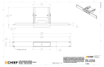
Figure A-1 M-IV System—Dimensions ............................................................. A-2
Service Manual
List of Tables
Table P-1 List of Acronyms for M-IV ................................................................ -xx
Table 1-1 M-IV Certifiable Components........................................................... 1-8
Table 3-1 Remote Console Operator Microprocessor Board DIP Switch (S1).... 3-1
Table 3-2 Host Push-buttons ............................................................................ 3-2
Table 3-3 Calibration Mode DIP Switch (S6) .................................................... 3-2
Table 3-4 Rotary Switch (S4) Settings ............................................................... 3-3
Table 3-5 Default DIP Switch (S7) Settings ....................................................... 3-4
Table 3-6 Host Peripheral Ports........................................................................ 3-5
Table 3-7 Setup Mode Default Worksheet...................................................... 3-10
Table 3-8 Additional Setup Mode Default Worksheet .................................... 3-11
Table 3-9 Exposure Technique Default Worksheet......................................... 3-12
Table 3-10 Compression Force ...................................................................... 3-13
Table 3-11 Exposure Mode Parameter Matrix................................................. 3-19
Table 3-11 Exposure Mode Parameter Matrix (Continued) ............................. 3-20
Table 3-12 X-Ray Tube Date Code Month Matrix .......................................... 3-21
Table 3-13 Tube Bias Voltage ........................................................................ 3-22
Table 3-14 Typical kV range vs. compressed thickness .................................. 3-25
Table 3-15 AEC Calibration Procedures ......................................................... 3-26
Table 3-16 Performance Test Worksheet—Large Focal Spot (Mo) .................. 3-29
Table 3-17 Performance Test Worksheet—Large Focal Spot (Rh) ................... 3-29
Table 3-18 Performance Test Worksheet—Small Focal Spot (Mo) .................. 3-31
Table 3-19 Performance Test Worksheet—Small Focal Spot (Rh) ................... 3-31
Table 4-1 Beam Quality Semi-Log (Half value Layer) ....................................... 4-4
Table 4-2 Reproducibility Worksheet............................................................... 4-6
Table 4-3 Linearity Worksheet ......................................................................... 4-7
Table 4-4 X-ray Field Adjustment Matrix—Large Focal Spot........................... 4-13
Table 4-5 X-ray Field Adjustment—Small Focal Spot ..................................... 4-15
Table 4-6 Error Codes .................................................................................... 4-24
Table 4-6 Error Codes (Continued) ................................................................. 4-25
Table 5-1 Operator Console Fuse Matrix.......................................................... 5-7
Table 5-2 Gantry A.C. Fuses ............................................................................ 5-8
Table 5-3 Gantry D.C. Fuse Matrix .................................................................. 5-8
Table 5-4 Circuit Board Jumper Settings......................................................... 5-10
Table 5-5 Operator Microprocessor Jumper Settings ...................................... 5-10
Table 6-1 Test Point Voltage Matrix ............................................................... 6-10
Table 7-1 High Voltage Inverter Board Test Point Voltages ............................ 7-14
Table 7-2 High Voltage Control Board Test Point Voltages............................. 7-14
Table 7-3 Tubehead Variables ....................................................................... 7-15
Table 7-4 Filament Control Board Test Point Voltages.................................... 7-15
Table 7-5 Generator Microprocessor Board Test Point Voltages ..................... 7-16
Table 7-6 Rotor Control Board Test Point Voltages......................................... 7-16
Table 7-7 Mains Power Board Test Point Voltages ......................................... 7-17
Table 7-8 Switch Test Points .......................................................................... 7-17
Service Manual
Table 7-9 C-arm Microprocessor Board Test Point Voltages ........................... 7-17
Table 7-10 Host Microprocessor Board Test Point Voltages ........................... 7-17
Table 7-11 Motor/Lamp Control Board Test Point Voltages ............................ 7-18
Table 7-12 VTA Motor Driver Board Test Point Voltages................................ 7-18
Table 7-13 Rotation Display Board Test Point Voltages.................................. 7-18
Table 7-14 ±15 V Power Supply Board Test Point Voltages............................ 7-19
Table 7-15 Power Distribution Board Test Point Voltages .............................. 7-19
Table 8-1 Tubehead Controller Board Cables................................................... 8-3
Table 8-2 Filament Protection Board Cables .................................................... 8-6
Table 8-3 Filament Protection Board Test Point Voltages ............................... 8-17
Table 8-4 Tubehead Microprocessor Test Point Voltages ............................... 8-17
Table 8-5 Tubehead Motor Driver Board Test Point Voltages ......................... 8-18
Table 8-6 Compression/AEC Position Display Test Point Voltages.................. 8-18
Table 8-7 Image Receptor Microprocessor Test Point Voltages....................... 8-19
Table 8-8 Bucky Interface Board Test Point Voltages...................................... 8-19
Table 8-9 Accessory Sensor Combinations..................................................... 8-23
Table 8-10 Image Receptor Sensor Combinations .......................................... 8-23
Table 9-1 Remote Console Replacement Parts ................................................. 9-1
Table 9-2 C-Arm Replacement Parts. ............................................................... 9-2
Table 9-3 Gantry Replacement Parts ................................................................ 9-3
Table 9-4 Miscellaneous Tools/Items ............................................................... 9-4
Table A-1 kV/mA Range................................................................................... A-6
Service Manual
Preface
1.0
Using the Service Manual
The first four chapters of this service manual are designed to provide a service representative with a sequence
for setting up and calibrating the M-IV. The remaining chapters detail the maintenance procedures. General
description of the contents of each chapter is as follows:
Chapter 1: General Information
Contains general system descriptions, x-ray, electrical and mechanical safety precautions, and compliance
information.
Chapter 2: System Installation
Contains information for unpacking, positioning, and installing the unit. Attaching the interconnections,
mounting the accessories, connecting to power, and the power up sequence are covered.
Chapter 3: System Setup
Contains information on system setup (switch settings and connections), functional checks, setting system
defaults, calibrating the exposure control system, and final set up checks.
Chapter 4: Performance/Compliance Checks and Adjustment Procedures
Contains the procedures that verify system compliance, including performance checks for the x-ray tube, the
automatic exposure control system, and the x-ray field.
Chapter 5: Covers, Panels, Fuses and Jumpers
Contains information detailing the removal of the unit’s covers and panels, the locations and ratings of the
fuses used on the system, and the jumper settings for each of the circuit boards.
Chapter 6: Operator Console Maintenance
Contains the information necessary to repair, and adjust the various assemblies and subsections of the Operator Console.
Chapter 7: Gantry Maintenance
This section provides the information necessary to repair, and adjust the various assemblies and subsections
on the Gantry, including the x-ray generation system and the C-arm movement system.
Chapter 8: C-arm Assembly Maintenance
This section provides the information necessary to repair, and adjust the various assemblies and subsections
of the M-IV C-arm, including the beam limiting assembly, the compression assembly, and the image receptor
support assembly.
Chapter 9: Parts List
Contains tabular listings of the replacement parts for the M-IV Mammography System.
Appendix A: Specifications
Contains system specifications, including performance specifications, x-ray tube and exposure specifications,
compression specifications and beam limiting specifications.
Preface
xix
Service Manual
1.1
Warnings, Cautions and Notes
Definitions of Warnings, Cautions and Notes used throughout this manual are as follows:
WARNING!
Warnings point out procedures that you must follow precisely to avoid injury to yourself or others.
CAUTION!
Cautions point out procedures that you must follow precisely to avoid damage to equipment, loss of
data, or corruption of files in software applications.
CAUTION!
ESD Cautions identify potential damage to electronic components caused by static electricity.
Always wear a grounded electrostatic discharge strap when handling static sensitive components
identified by this caution.
Note…Notes indicate important information that must be followed to ensure the proper operation
of the system.
2.0
Acronym List
The following table provides a list of the common Acronyms used throughout the M-IV Service Manual.
Table P-1: List of Acronyms for M-IV
Acronym
xx
Definition
21 CFR
FDA Code of Federal Regulations, Title 21
ACR MAP
American College of Radiology Mammography Accreditation Program
ACR/CDC
American College of Radiology/Center for Disease Control
AEC
Automatic Exposure Control
B.E.M.
Breast equivalent material
CPT
Common Procedural Terminology
DSM
Digital Spot Mammography
DMM
Digital Multimeter
EMC
Electro-magnetic Compatibility
EMI
Electro-magnetic Interference
EMO Switch
Emergency Off Switch
ESD
Electro-static Discharge
Preface
Service Manual
Table P-1: List of Acronyms for M-IV
Acronym
Preface
Definition
F.A.S.T.
Fully Automatic Self-Adjusting Tilt Paddle
H.V.
High Voltage
HTC
High Transmission Cellular Grid
HVL
Beam Quality Half-Value Layer
IR
Image Receptor
IRSD
Image Receptor Support Device
LVPS
Low Voltage Power Supply
Mag
Magnification mode
Mo
Molybdenum
MQSA
Mammographic Quality Standards Act
MPU
Microprocessor Unit
N
Newtons
OD
Optical Density
Rh or Rho
Rhodium
RIS
Radiology Information System
SID
Source to Image Distance
SL or STL
StereoLoc II
VAC
Volts, Alternating Current
VDC
Volts, Direct Current
VTA
Vertical Travel Assembly
xxi
Service Manual
xxii
Preface
Service Manual
Chapter 1: General Information
1.0 Intended Use
The M-IV Mammography System is intended to produce radiographic images of the breast. Its specific
intended use is for screening and diagnostic mammography.
2.0
Introduction
The M-IV Mammography System combines LORAD Clean Power Mammography technology with a microprocessor controlled unit to make a complete diagnostic imaging system. The full-featured machine provides
manual or automatic x-ray control and accommodates a full range of options, including stereo tactic localization and digital imaging capabilities.
3.0
Unit Description
The M-IV is equipped with a bi-angular, dual focal spot x-ray tube, and features four menu-driven exposure
modes:
•
•
•
•
Manual - all exposure factors entered by user
Auto-Time - system determines exposure duration
Auto-kV - system determines exposure kV and duration
Auto-Filter - system determines all exposure factors
The unit accommodates all LORAD manufactured attachments, such as cassette holders, Bucky devices,
Compression Paddles, Localization Paddles, and the Magnification Table. The unit also adapts for use with
the LORAD StereoLoc II Localization and Biopsy System, and the LORAD DSM Digital Spot Mammography
System.
Note …LORAD StereoLoc II and LORAD DSM are not available for use with the M-IV Mobile.
The unit’s modular design separates the operator interface (Operator Console) and the patient support devices
(Gantry). This permits configuration of the M-IV to differing space allotments including installation as a
mobile unit (M-IV Mobile).
The M-IV incorporates multiple microprocessors that control the user interface, mechanical operations (C-arm
and collimator movement), the x-ray generation system, and the automatic exposure control system.
The control system contains built-in diagnostic routines that monitor operation before, during, and after an xray exposure. If these diagnostic routines detect a malfunction, further operation is prevented until the
detected fault is cleared. All fault messages are displayed on the Operator Console Flat Panel Display.
Chapter 1: General Information
1-1
Service Manual
3.1
Required Tools and Equipment
The following is a list of the tools and equipment
necessary to perform the maintenance procedures
detailed in this manual.
•
•
•
•
•
•
•
•
•
•
•
•
•
•
•
•
•
•
•
•
•
•
•
•
•
•
•
•
Standard Hand Tools
Oscilloscope
Digital Multimeter (DMM)
Hex (Allen) Wrench Set - standard
Light Detector Model 268P (or equivalent)
Light Meter - UDT Instruments, Model 351
(or equivalent)
Radiation Meter with probe (calibrated in
the Mammographic ranges)
Aluminum Filter Pack - Ultra-high purity
type 1145 (99.99% pure)
3/8” Drive Socket Set
P.M.M.A. Acrylic Attenuators (or B.E.M.) - 1
cm thick, min. of 10 x 12.5 cm
P.M.M.A. Acrylic Attenuators (or B.E.M.) - 2
cm thick, min. of 10 x 12.5 cm
P.M.M.A. Acrylic Attenuators (or B.E.M.) - 4
cm thick, min. of 10 x 12.5 cm
High Voltage Divider with a ratio of
10,000:1 or 100,000:1
High Voltage Adapter Cable (LORAD P/N 2425-3015)
mAs Meter
Light Field Alignment Bars (9-060-0173)
Light/X-ray Field Template (9-060-0140)
Field Service Belt Adjustment Tool (9-0610107)
Loctite, 242 Blue (2-580-0542)
Masking Tape
Laptop Computer (P.C.) with serial port
Mammography Phantom—ACR MAP
PLCC EPROM Remover
Serial Cable with 2 x 5 header on one end
Lead Shield/Blocker - Approximately 4 x 4
cm
Feeler Gauges - 0.015 and 0.020
Compression Scale/Force Gauge
Aluminum Aperture for Light Meter - 1 mm
diameter
Note…B.E.M. refers to breast equivalent
material, such as BR-12, 50/50 Breast
Tissue equivalent material, or P.M.M.A.
Acrylic.
Chapter 1: General Information
1-2
Service Manual
4.0
Safety
This portion of the manual details electrical, mechanical, and radiation safety, as well as precautions concerning static electricity and magnetic media storage. The equipment complies with IEC 601 (General, Collateral
and applicable Particular Standards), UL 2601 and CSA 22.2601.
4.1
Electrical Safety
The system is classified as CLASS I, TYPE B permanently connected equipment as per IEC 601-1 and
Class II Medical Devices per 21 CFR 892.1710.
There are no special provisions to protect the system
from flammable anesthetics or ingress of liquids.
4.2
Static Electricity and Magnetic
Field Safety
Always be aware of the effects static electricity has
on electronic components. Take precautions for the
safe handling and storage of electronic media.
Three Emergency OFF (EMO) switches are provided.
Two switches are located on the Gantry (one on
each side) and the third switch is located on the
operator console. Each of these switches disables
power to the entire system.
CAUTION!
Electronic components within the unit are
extremely sensitive to static electricity.
ALWAYS use a grounding electrostatic strap
when handling these sensitive components.
WARNING!
CAUTION!
Only qualified electronic technicians who
are certified and experienced in the maintenance and repair of high voltage x-ray
equipment should attempt to service this
equipment.
The floppy diskettes store data magnetically. DO NOT store or place any magnetic
media near or on devices which produce
magnetic fields or stored data may be lost.
4.3
WARNING!
LETHAL voltages are present within the
interior of the unit. Use extreme caution to
avoid contacting, directly or indirectly
(through tools), any connector pins, terminals, or test points. Remove all jewelry
before working on the unit, and avoid
wearing loose fitting clothing.
WARNING!
Mechanical Safety
•
•
•
The C-arm rotation motor stops upon loss of
power and braking is ensured.
The Automatic Compression Release Mode
is disabled when a Localization Paddle is
installed.
All C-arm functions (vertical drive, rotation,
compression up/down, compression
release, light field, etc.) are simultaneously
operable. Vertical drive and rotation are disabled during the presence of at least 13 lb
of compression force.
Never perform service alone. Only service
this equipment in the company of someone
who is capable of rendering aid should an
accident occur.
1-3
Chapter 1: General Information
Service Manual
4.4
Radiation Safety
The radiation safety of the unit complies with all
requirements of 21 CFR, Part 1020, and complies
with IEC 601.
The operator control panel contains two x-ray exposure buttons which must be pressed simultaneously
for the entire duration of the exposure and released
before initiating another exposure. An audible tone
will sound for the entire time x-rays are produced.
The exposure duration is controlled by the following
normal conditions:
•
•
•
•
The X-ray exposure switches must be held
continuously
By the microprocessor pre-set back-up-time
By an independent “safety” hardware backup-timer
By detection of a generator fault.
The control electronics prevent the unit from initiating an X-ray exposure unless:
•
•
•
•
The cassette is installed with Bucky use
The room door interlock is closed
The X-ray exposure footswitch interlock is
closed (NYC requirement.)
Two X-ray switches must be activated simultaneously.
The radiation shield provides a minimum of 0.5 mm
of lead equivalent attenuation at 35 kV.
Chapter 1: General Information
1-4
Service Manual
5.0
Unit Layout
The M-IV Mammography Unit consists of three major assemblies:
•
•
•
5.1
the Operator Console
the Gantry
the C-arm
The Operator Console
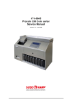
Legend for Figure 1-1
The Operator Console controls x-ray exposures
through the operator interface (Flat Panel Display
screen and keyboard on the Console). Data and
technique inputs are made via the keyboard while
the screen displays all exposure options and selections for the selected exposure mode (Manual, AutoTime, Auto-kV, or Auto-Filter). Data fields on the
screen list patient information (name, identification
number, gender, etc.), exam data (view, CPT code),
and technologist identification data. Status lines also
inform the user as to the condition of the accessories
(printer, AutoFilm ID, compression, image receptor),
in addition to the current date and time. The display
screen provides illumination for the keyboard and is
manually adjustable, forward and back.
1.
2.
3.
4.
5.
6.
7.
8.
9.
Display Screen
Emergency OFF Switch (left side of console)
Data Entry / Exposure Control Keyboard
AutoFilm ID
Cassette Storage (Both Sides)
Radiation Shield
Bar Code Reader (optional)
Floppy Disk Drive
Input Power/Data Cable Connector Panel
(rear of console)
10. Keyboard Illuminator
The Operator Console houses the following components:
6
•
•
•
•
•
•
•
•
•
•
•
Keyboard (for data and technique input)
X-ray Exposure Buttons
Console Display (operator interface)
AutoFilm ID
Low Voltage Power Supply
Operator Interface Microprocessor
System Peripheral (floppy disk drive)
ON and OFF Buttons
Remote Compression Release Button
Emergency OFF Switch
Keyboard Illuminator
Refer to Figure 1-1 to identify the Operator Console
components.
1
10
2
7
3
4
8
5
9
Figure 1-1: M-IV Operator Console—Components
1-5
Chapter 1: General Information
Service Manual
5.2
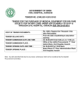
The Gantry and C-Arm
Legend for Figure 1-2
The Gantry is the main support for the C-arm and
tubehead assembly. It is permanently connected to
the input power source, and supplies power to all
unit subsystems through an isolation transformer.
1.
2.
3.
4.
5.
The following components or subsystems are found
in the Gantry:
•
•
•
•
•
•
6.
7.
8.
9.
10.
11.
12.
13.
14.
15.
16.
Exposure Control Electronics
High Voltage Generator
C-arm Rotation Drive
C-arm Vertical Drive
Power Distribution (Input Power Circuit
Breaker)
Vertical Travel Assembly
The M-IV C-arm, which suspends from the pivot
tube on the Gantry, is made up of the following
components or subsystems:
•
•
•
•
•
•
•
•
X-ray Tube
Beam Limiting Device
Compression Device
C-arm Controls
IRSD
Accessory Detect Systems
Automatic Exposure Control System
Bucky Device Control
Refer to Figure 1-2 to identify the Gantry and C-arm
components.
C-arm Angle Display
Tubehead
Tubehead Controls
Face Shield
Compression Displays and AEC Position
Display
Compression Device
Emergency OFF Switch (2)
IRSD
Dual Function Footswitch
Patient Handle
C-arm Controls
C-arm Pivot Tube
Circuit Breaker (rear of gantry)
Footswitch Receptacles (rear of gantry)
C-arm Rotation Control (rear of IRSD)
AEC Detection Position Handle (bottom of
IRSD)
1
2
3
7
10
4
5
11
6
12
8
15
16
13
14
COMPRES
SION
C-ARM
C-ARM
9
COMPRESSION
C-ARM
Figure 1-2: M-IV Gantry and C-arm—Components
Chapter 1: General Information
1-6
Service Manual
6.0
Compliance Data
The following section details the M-IV compliance requirements and the manufacturer’s responsibilities.
6.1
Responsibility Statement
LORAD is responsible for the effects of reliability
and performance of this equipment with the following provisions:
•
•
•
The electrical installation of the room complies with the appropriate requirements.
The equipment is used in accordance with
instructions for use.
To ensure safe operation, assembly operations, extensions, readjustments, modifications, or repairs must be performed by
authorized persons only.
6.2
Compliance Statement
The manufacturer of this device complied with the
following requirements applicable at the time of
manufacture:
•
•
•
•
The system is designed, tested, and classified to
comply with the following requirements:
•
•
•
•
•
•
•
•
•
•
•
Chapter 1: General Information
ISO 9001
ISO 13485
EN 46001
FDA Quality System Regulation (QSR), 21
CFR 820
IEC 601-1
IEC 601-2-7
IEC 601-2-32
IEC 601-1-2
IEC 601-2-28
IEC 601-2-45
EMC Directive
Medical Device Directive
UL 2601
CSA 22.2 No. 601.1
21 CFR Subchapter J
1-7
Service Manual
6.3
Certifiable Components
These components are identified using individual serial numbers (refer to Table 1-1)
Table 1-1: M-IV Certifiable Components
ITEM
MANUFACTURER
MODEL #
LABEL #
LOCATION
X-ray Tube
Toshiba
E7290AX
4
Tubehead
X-ray Tube
Varian
M113R/B115
4
Tubehead
Bucky (18 x 24 cm) - Linear Grid
LORAD
4-000-0242
2
Accessory
Bucky (24 x 30 cm) - Linear Grid
LORAD
4-000-0244
2
Accessory
Bucky (18 x 24 cm) - HTC Grid
LORAD
4-000-0241
2
Accessory
Bucky (24 x 30 cm) - HTC Grid
LORAD
4-000-0243
2
Accessory
Magnification Table
LORAD
4-000-0246
2
Accessory
High Voltage Generator
LORAD
4-000-0014
2
Gantry
Beam Limiting Device
LORAD
4-000-0029
2
Gantry
X-ray Control
LORAD
4-000-0002
2
Console
Image Receptor Support Device
LORAD
4-000-0140
2
C-arm
Image Receptor Support Device
LORAD
4-000-0141
2
C-arm
IMPORTANT! When replacing a certified component that is concealed by a surface
(i.e., cover, panel, etc.), the component’s duplicate label on the exterior of the
unit MUST BE replaced at the time of service.
IMPORTANT! When replacing a surface (i.e., cover, panel, etc.) that has a certified
component duplicate label(s), a label(s) that represents the certified component
label(s) MUST BE placed on the new surface at the time of service.
6.4
Compliance and Identification Label Locations
The unit conforms to all applicable FDA regulations. Labels addressing the certifiable components are fixed to
the unit at several points. Refer to Figure 1-3.
Obtain each device’s serial number from the main identification label and write it down on the inside cover of
both the Operator’s and Service manuals. The Main Frame serial number is used to track units for warranty
and service purposes, and will be requested should it become necessary to contact LORAD regarding the
device.
Note…LORAD Bucky’s 18 x 24 cm and 24 x 30 cm are certified components which are not subject
to 21 CFR1020.30(d) and therefore do not have to be reported on form FDA 2579 (Ref BRH:
Doc MA3499).
1-8
Chapter 1: General Information
Service Manual
Figure 1-3: Label Locations
Chapter 1: General Information
1-9
Service Manual
1-10
Chapter 1: General Information
Service Manual
Chapter 2: System Installation
1.0
Unpacking The Unit
This section contains procedures for unpacking, setting up, positioning, and installing the M-IV Mammography System. Procedures for measuring the input power receptacle voltage, and for tapping the unit’s isolation
transformer are also included.
1.1
Receiving Instructions
CAUTION!
The unit is shipped in three main crates which contain the following:
•
•
•
the Gantry
the Operator Console
the Radiation Shield
Before opening the crates, perform the following:
•
•
•
Inspect each crate and box for external
damage
Note any observable damage on the shipping manifest
Notify LORAD of any incident
If shipping damage is of a concealed nature, contact
the carrier as soon as such damage is found, and
request an inspection for shipping damage. Normally, any claims for shipping damage must be completed within 15 days of receiving the shipment.
After the external inspection, perform the following:
•
•
•
Avoid damaging the Radiation Shield by
impact or scratching. DO NOT store the
radiation shield flat or damage may occur.
Open all crates and boxes
Check contents against packing list / sales
order
Report ALL discrepancies to LORAD
If it is necessary to repack any items for future installation, use the original packaging materials.
CAUTION!
DO NOT attempt to lift or move the Gantry by the C-arm, or by either hinged door
on the left and right side of the Gantry
frame, or damage may occur.
Chapter 2: System Installation
1.2
Un-crating—Gantry
The Gantry is crated and shipped in the prone position. After removal from the shipping crate, it will
be necessary to upright the Gantry before it can be
mounted into position.
1. Cut the straps that secure the cardboard
shipping carton to the shock-mounted
wooden pallet.
2. Lift the carton from the wooden pallet.
3. Carefully remove all shipping materials (i.e.,
foam padding, tie-downs, straps, shipping
wrap, etc.) that protect the Gantry during
shipment.
4. Lift all accessory boxes from the pallet.
5. Carefully push the entire Gantry assembly
forward, in the direction of the base plate
“dolly”, until the “dolly” frame clears the
pallet (approximately 1 foot). (See Figure 21: Un-crating the Unit.) Use two people
(MINIMUM) to lift the Gantry upright onto
the attached shipping “dolly”.
6. Carefully roll the Gantry to the installation
site.
Note…It is the responsibility of the dealer to
return the Gantry dolly to LORAD via the
supplied shipping documents. Refer to
LORAD Field Service Technical Bulletin
(No. 94-0093) for policy details.
2-1
Service Manual
1.3
Un-crating—Operator Console
The Operator Console is crated and shipped upright,
with the console display not installed and without
the radiation shield attached. After removal from the
shipping crate, the Operator Console may be carried
to its final mounting location.
1. Cut the straps that secure the cardboard
shipping carton to the shock-mounted
wooden pallet.
2. Lift the carton from the wooden pallet.
3. Carefully remove all shipping materials (i.e.,
foam padding, tie-downs, straps, shipping
wrap, etc.) from the Console.
4. Lift all accessory boxes from the pallet,
including the console display.
5. Carefully lift the Operator Console off the
pallet and place it gently on the floor.
1.4
Unpacking—Accessories
The console display screen and all accessories are
packed in separate boxes and containers which are
stored in one of the two main shipping containers
(Gantry or Console). The accessory containers are
specially designed to minimize shipping damage
and to facilitate equipment storage. Note, however,
that the radiation shield is shipped in its own box.
1. Check each item for damage.
2. If it is necessary to repack any items for
future installation, use the original packaging materials.
3. Open the radiation shield container and
carefully remove the glass shield.
4. Check the shield for nicks, cuts, scratches or
other damage.
Figure 2-1: Un-crating the Unit
5. Place all accessories in a storage area or
compartment near the installation site.
Note….The storage area should provide convenient access to each accessory, but should
not interfere with C-arm or patient movement.
2-2
Chapter 2: System Installation
Service Manual
2.0
Unit Installation
Note that the installation site (exam room) must be properly prepared by qualified personnel prior to installing
the unit. Verify that the following are complete prior to transporting the unit to the installation site:
•
•
•
Floor modifications (anchor bolts for Gantry and Console)
Pre-installed Wire-runs and Conduits
Voltage source facilitating a hard wire configuration
Position the Gantry and the Operator Console in the appropriate room. Pay particular attention to the following:
•
•
•
Clearances for C-arm rotation and rear Gantry access
Positioning of Console and radiation shield relative to x-ray source
Space for patient movement
Avoid obstructions in the room that may hinder access to the Operator Console or the patient. Provide convenient storage for patient records, film, cassette holders, and other accessories.
2.1
Installation—Gantry
The Gantry mounts to the floor onto pre-installed,
threaded floor anchors. Four floor anchors are
required to secure the Gantry to the floor. (See Figure 2-2: Installation—Gantry.) It is the responsibility
of the health-care facility to ensure that the Gantry
mounting points (floor anchors) meet the federal,
state, and/or local building codes for floor mounting
and load requirements, and all OSHA requirements
for safety.
5. Secure the Gantry to the floor using the recommended anchor bolts and washers.
1. Move the Gantry into position near the predrilled floor anchor holes.
2. Remove the bolts that secure the Gantry to
the shipping “dolly”, then carefully remove
the “dolly” from beneath the Gantry baseplate.
WARNING!
It will require two people to remove the
unit safely from the shipping dolly.
Figure 2-2: Installation—Gantry
3. Carefully move the Gantry so that the baseplate mounting holes align over the
threaded floor anchors.
CAUTION!
NEVER maneuver the Gantry by lifting,
pulling, or pushing on the C-arm or the
tubehead assemblies.
4. Level the Gantry by adjusting the threaded
Inserts in each of the baseplate mounting
holes.
Chapter 2: System Installation
2-3
Service Manual
2.2
Installation—Operator Console
The Console mounts to the floor onto four preinstalled floor anchors (threaded). It is the responsibility of the health-care facility to ensure that the
Console mounting points (floor anchors) meet the
federal, state, and/or local building codes for floor
mounting and load requirements, and all OSHA
requirements for safety.
1. Remove the front panel from the Operator
Console to access the mounting holes (refer
to Chapter 5: Covers, Panels, Fuses and
Jumpers, Section 2.1 for remove and replace
procedures for the Operator Console Covers).
2. Move the Operator Console near the preinstalled floor anchors. Note that it may
require two people to move the console into
position.
3. Carefully position the Console over the floor
anchors so that the mounting holes align
over the threaded floor anchors.
Mounting Holes
(Left Side)
Figure 2-3: Installation—Operator Console
4. Secure the Console to the floor using the
required anchor bolts and washers. (See Figure 2-3: Installation—Operator Console.)
5. Install the console display as per Section
2.2.1 below.
6. Replace the Operator Console front panel
as per Chapter 5: Covers, Panels, Fuses and
Jumpers, Section 2.1.
2-4
Chapter 2: System Installation
Service Manual
2.2.1
Installation—Console Display
3
The M-IV Console Display mounts to a bracket
beneath the control panel which must be removed
to access the mounting hardware (refer to Chapter 5,
Section 2.1 for remove and replace procedures for
the Operator Console Covers).
2
1. Remove the Operator Console control panel
as per Chapter 5, Section 2.1.
2. Remove the hardware that fastens the console display mount (Item 1, Figure 2-4) to
the console frame (Item 2, Figure 2-4). Lift
the mount out of the console.
1
3. Install the console display (Item 3, Figure 24) onto the mount, then attach the ground
wire provided.
4. Route the console display cables through
the slot in the console top shelf.
5. Connect the Console Display ribbon cable
to TJ28 on the Operator Interface Microprocessor Board (Item 4, Figure 2-4).
6. Connect the backlight connector to TJ27 on
the Operator Interface Microprocessor
Board.
7. Connect the keyboard LED cable to P4 (part
of the sub-panel cable harness in the front
component compartment {Item 5, Figure 24}).
5
8. Align the holes in the display and mount
with the holes in the console frame. Install
and tighten the mounting hardware.
9. Replace the Operator Console control panel
as per Chapter 5, Section 2.1.
4
Figure 2-4: Installation—Console Display
Chapter 2: System Installation
2-5
Service Manual
2.3
Installation—Footswitches
The system permits attachment of two dual-function
footswitches that plug into receptacles inside the
Gantry. Use the following procedure to install the
footswitches.
WARNING
To avoid accidental footswitch activation,
keep both footswitches clear of the patient
and C-arm setup area.
J2
CONSOLE
POWER
J21
HI VOLT
ENABLE DSM
J4
LEFT
FOOTSW
J0
SERIAL PORT
DIGITIZER
1. Remove the lower rear panel from the Gantry by removing the six cover screws.
2. Connect the footswitches to the left and
right footswitch receptacles (J3 and J4) by
aligning the key to the key hole and pushing
the connectors straight in. (See Figure 2-5:
Footswitch Connections.)
Figure 2-5: Footswitch Connections
Note…Either footswitch can be connected to
either footswitch receptacle.
3. Replace the lower rear panel to the gantry
using six cover screws.
4. To disconnect the footswitch, repeat steps 1
through 3 but instead of pushing the connectors in (Step 2), disconnect by pulling
the connectors straight out.
2-6
Chapter 2: System Installation
Service Manual
2.4
Installation—Radiation Shield
The radiation shield and the shield support are
shipped in separate containers and must be fastened
to the Console. Set the cable cover aside for mounting after the cable connections are made to the
remote console. The two halves of the shield support are shipped already attached. Separate the two
halves by lifting the rear shield support slightly, and
then pulling it away from the front shield support.
Follow the instructions below to install the radiation
shield to the M-IV Operator Console.
Note …The M-IV Mobile unit does not come
with an operator shield. Shielding will be
provided and installed by the M-IV Mobile
installer at time of system installation.
1. Position the front shield support so that the
mounting holes align with the threaded
holes in the rear of the operator console.
2. Secure the front shield support with the four
bolts supplied.
3. Lift the radiation shield and place it on the
support shelf (attached to the front shield
support) with the LORAD logo facing the
patient.
4. Align the holes in the shield with the
threaded holes in the front support.
5. Position the protective plates (2) over the
shield mounting holes.
6. Secure the plates and the shield to the front
shield support using the four bolts supplied.
(See Figure 2-6: Installation—Radiation
Shield.)
7. Position the hooks on the rear shield support so that they align with the slots in the
front shield support.
8. Insert the hooks into the slots, then slide the
rear support down to secure in place.
Figure 2-6: Installation—Radiation Shield
9. Mount the front and rear fascia strips onto
the shield support as shown.
Note…The fascia strips are self-adhesive and
are used to cover the gap between the
shield and the shield support.
Chapter 2: System Installation
2-7
Service Manual
2.5
Installation—Bar Code Reader
This procedure details installing the optional Bar
Code Reader Wand and the Utility Shelf. Note that
this procedure is only valid for units that are shipped
Bar Code Reader “ready”. Refer to Figure 2-7
throughout the following.
5. Position the Utility Shelf so that the three (3)
screws align with the mounting holes in the
side of the Control Console. Tighten each
screw to secure the shelf and mounting
plate.
6. Replace the previously removed covers.
1. Make sure system power is OFF. Remove
the Control Console to access the top shelf
components. Remove the Console front
cover. Refer to Chapter 5: Covers, Panels,
Fuses and Jumpers for cover removal procedures.
2. Slip the “D”-sub connector of the Reader
Wand through the cutout in the right side of
the Control Console. Route the connector
around the back side of the AutoFilm ID
Assembly.
3. Slip the Reader Wand connector through
the access hole in the rear of the top shelf,
then route it downward toward the Operator Microprocessor Board. Attach the connector to TJ24 on the Operator
Microprocessor.
Figure 2-7: Installing the Bar Code Reader
4. Secure the Reader Wand Cord to the existing wiring harness using several cable ties.
2-8
Chapter 2: System Installation
Service Manual
3.0
M-IV Interconnections
The following procedures detail making the connections between the Gantry and the Operator Console and
how to connect the unit to power. Refer to Figure 2-8 throughout the following.
3.1
Interconnections—Gantry to
Console
1. At the rear of the remote console, connect
one end of the power cable (Item 1, Figure
2-8) to the “Power In” receptacle (Item 2,
Figure 2-8) on the console connector panel.
Legend for Figure 2-8
1. Power Cable
2. Power In receptacle
3. J2 Console Power receptacle
4. Data Cable
2. At the rear of the Gantry, remove the lower
rear gantry cover. Route the free end of the
power cable by the pre-installed conduits /
wire-runs to the Gantry. Fasten the power
cable connector to the “J2 Console Power”
receptacle (Item 3, Figure 2-8) on the Gantry connector panel.
5. Host to Micro Comm receptacle
3. Connect one end of the data cable (Item 4,
Figure 2-8) to the “Host to Micro Comm”
receptacle (Item 5, Figure 2-8) on the console connector panel.
10. Printer Parallel Port
4. Route the free end of the data cable by the
pre-installed conduits / wire-runs to the
Gantry. Fasten the data cable connector to
the “J1 Console Data” receptacle (Item 6,
Figure 2-8) on the Gantry connector panel.
13. Input Power Terminal Block
6. J1 Console Data receptacle
7. Data and Power Cable Ground Wires (Qty
4)
8. Ground Stud
9. Ground Stud
11. DSM Port
12. Isolation Transformer
14. Input Power Cord
15. Ground Wire
5. Fasten the data and power cable ground
wires (4 wires, Item 7, Figure 2-8) and the
Gantry to Console ground wire to the
appropriate ground studs (Items 8 and 9,
Figure 2-8).
6. For systems with the optional Label Printer,
connect the printer’s data cable connector
to the “Printer” parallel port (Item 10, Figure
2-8) on the Console connector panel. Connect the printer power cable to local power.
7. For systems with optional DSM, connect the
DSM data cable connector to the “DSM”
port (Item 11, Figure 2-8) on the console
connector panel. Connect the DSM power
cable to local power.
8. Install the cable cover (set aside during radiation shied installation procedures) on the
base of the Operator Console.
Chapter 2: System Installation
2-9
Service Manual
Backside - Gantry
6
4
3
J3
RIGHT
FOOTSW
J2
CONSOLE
POWER
J1
CONSOLE
DATA
J4
LEFT
FOOTSW
1
240V~
230V~
220V~
208V~
N
200V~
12
POWER
ON
X-RAY
ON
7
9
13
CIRCUIT
BREAKER
WHITE (P/O 14)
BLACK (P/O 14)
GREEN (P/O 14)
*
14
15
Backside - Console
4
DSM
(Optional)
1
LABEL
PRINTER
(Optional)
11
POWER IN
HOST TO
MICRO COMM
EXT. XRAY &
COMPRESSION
RELEASE
AUI
DSM
THIN NET
10 BASE T
GND
COM "B"
COM "C"
MODEM
PRINTER
11
2
5
7
8
*Must be installed on bottom of Ground Connector to meet safety requirements.
Figure 2-8: Unit Interconnections
2-10
Chapter 2: System Installation
Service Manual
240V~
230V~
220V~
208V~
240V~
230V~
220V~
208V~
200V~
N
240V~
230V~
220V~
208V~
200V~
200V~
208V~
220V~
230V~
240V~
208V~
220V~
230V~
240V~
Note…The above requirements are met if the
unit is operated on a line with no greater
than 3% voltage drop under maximum
operating load (Large Focal Spot @ 32 kV).
Exceeding this requirement necessitates
corrective action by the site.
230VAC
6. Verify that the line impedance does not
exceed 0.16 ohms (200 V line), or 0.2 ohms
for all other input voltages (208 V, 220 V,
230 V, or 240 V).
240VAC
5. Verify the isolation transformer taps are
wired to match the previously measured
source voltage, if not, configure the isolation transformer input wiring and tap as
shown in Figure 2-9.
N
4. Remove the Gantry’s lower rear panel to
access the input power terminal block.
200V~
3. Make sure the unit is OFF and that the input
power cord is detached from the mains.
N
Note…The mammography unit’s isolation
transformer is configured at the factory to
match the voltage specified at the time the
unit was ordered.
208VAC
After determining the input voltage range, verify that
unit’s isolation transformer tap (Item 12, Figure 2-8)
is correctly set, or re-configure the transformer taps
as required by performing the following:
220VAC
2. Inquire as to any history of voltage fluctuations of voltage-related problems that have
occurred in other equipment at the site.
N
1. Measure the voltage at the mains disconnect.
N
The M-IV isolation transformer must be configured
to match the power source at the site. This portion
of the manual details the steps to properly configure
and connect the mammography unit to a voltage
source. Before connecting the unit to a mains disconnect, perform the following:
200V~
Connecting to Power
200VAC
3.2
Figure 2-9: Input Power Configuration
Chapter 2: System Installation
2-11
Service Manual
Perform the following to attach the system to a
source of power.
PROTECTIVE
EARTH CONDUCTOR
1. Connect the input power cord (Item 14, Figure 2-8) to the input power terminal block
(Item 13, Figure 2-8) on the rear of the Gantry. Refer to Figure 2-10.
2. Permanently wire the opposite end of the
input power cord to a disconnect panel.
3. Replace the lower rear Gantry cover.
CAUTION!
The connection of the protective earth terminal is critical to the safety of the operator and the patient. ALWAYS ensure that
this connection is made prior to replacing
the rear panel. Under no circumstances
should this equipment be operated with the
protective earth connector not in place.
L
N
3-310-0638
Figure 2-10: Connecting to Source
4.0
System Power Up
For normal operation, always perform the following checks prior to applying power to the M-IV:
•
•
•
Check that the primary (source) power circuit breaker is ON.
Check that the M-IV circuit breaker, on the back of the Gantry, is ON.
Verify that ALL Emergency OFF Switches (two on the Gantry, one on the Console) are in the RESET
position.
When complete, follow the start-up sequence below to power up the system.
1. On the Operator Console, press the ON button to apply power.
2. The system performs a series of checks of the internal subsystems. During this time, the remote microprocessors activate, and report to the Host microprocessor.
During boot up, the current software versions will be displayed on the bottom of the screen (will stay on
screen for approximately 10 seconds. To freeze view, press shift + view at same time, repeat to un-freeze
view.)
Failure of a subsystem to report causes an error condition. To hold the start-up sequence so that the error message remains on the screen, press the SHIFT and VIEW keys. To resume, press the SHIFT and VIEW keys
again.
3. If, during the diagnostic checks, the system detects a fault or error condition, a message appears in
the Message Area.
4. After the self-diagnostic checks, the display screen shows the Run Mode, and the start-up sequence is
complete.
Note …After turning on the system, a tone will sound, and the Operator Console display will illuminate. These associated indicating devices indicate that system power is applied.
2-12
Chapter 2: System Installation
Service Manual
Chapter 3: System Setup
1.0
Switches and Connections
The Remote Console Operator Interface Microprocessor Board contains one DIP Switch (S1). Refer to Chapter 6: Operator Console Maintenance, Figure 6-1 for board location within the Remote Console.
The Host Microprocessor Board contains a Rotary Selection switch (S4), four push-button switches (S1, S2,
S3, and S5), a Calibration Mode DIP Switch (S6), a Default DIP Switch (S7), and an LED display. Refer to
Chapter 7: Gantry Maintenance, Figure 7-1 for board location within the Gantry. The tables that follow detail
M-IV switch and jumper configurations. Refer to Figure 3-1 for switch identification and location on the Host
Microprocessor Board.
1.
2.
3.
4.
Rotary Button (S4)
LED Display Pad
Save Button (S1)
Select Button (S2)
5.
6.
7.
8.
Decrease Button (S3)
Increase Button (S5)
Calibration Mode DIP Switch (S6)
Default DIP Switch (S7)
2
3
4
5
6
7
8
1
Figure 3-1: Host Microprocessor Switches
1.1
1.1.1
Remote Console Switch Settings
Operator Microprocessor Board DIP Switches
Table 3-1 identifies the Remote Console Operator Microprocessor Board DIP switch (S1) functions:
Table 3-1: Remote Console Operator Microprocessor Board DIP Switch (S1)
SWITCH
1
2
3
4
5
6
7
8
ON FUNCTION
OFF FUNCTION
Reverse Video
Normal Video
LCD Display
EL Display
DD/MM/YYYY Date format
MM/DD/YYYY Date format
Not Used
Test Screen
ID & Name Required For “Ready”
No ID & Name Required for “Ready”
Floppy Disk Drive Installed
No Floppy Disk Drive Installed
Check Floppy upon Run Screen Access Skip Floppy check upon Run Screen Access
Not Used
Load Defaults on Power Up <Shift> + <Clear>
Chapter 3: System Setup
3-1
Service Manual
1.2
1.2.1
Host Microprocessor Board Switch Settings
Host Push-buttons (S1, S2, S3, S5)
Use the four push-buttons, S1, S2, S3, S5 (Items 3 through 6, Figure 3-1) below the LCD Display (Item 2, Figure 3-1) to switch among the variables for the selected calibration, to increase or decrease the displayed variables, and to save the changed information (see Table 3-2).
Table 3-2: Host Push-buttons
SWITCH
S1
S2
S3
S5
1.2.2
FUNCTION
Save
Select
Decrease
Increase
Calibration Mode DIP Switch (S6) Settings
Prior to calibrating any system parameter, it will be necessary to first set the appropriate switches on the Calibration Mode Dip Switch, S6 (Item 7, Figure 3-1) as shown below:
Table 3-3: Calibration Mode DIP Switch (S6)
SWITCH
1
2
3
4
5
6
7
8
STATUS
see below
see below
ON
OFF
ON
OFF*
OFF
ON
OFF*
ON
OFF*
ON
OFF*
S6-1/S6-2 SWITCH SETTING
OFF/OFF
OFF/ON
ON/OFF
ON/ON
FUNCTION
Peripheral Monitor (KJ26) Select
Peripheral Monitor (KJ26) Select
Load TOSHIBA defaults
Load VARIAN defaults
Calibration Mode
Run Mode
NOT USED
5 second STANDBY after x-ray
30 second STANDBY after x-ray
Host Alarm Enabled
Host Alarm Disabled
Alternate S4 function 1 **
Alternate S4 function 2 **
PERIPHERAL (Monitored at KJ26)
Tubehead
Generator
Motor
Image Receptor
*Normal Operating Position
**Refer to Table 3-4, Rotary Switch (S4) Settings
3-2
Chapter 3: System Setup
Service Manual
1.2.3
Rotary Switch (S4) Settings
The Rotary Selection switch, S4 (Item 1, Figure 3-1) is a 16 position switch numbered 0 through 9, and A
through F. Each switch position selects a calibration parameter (see Table 3-4). The LCD display (Item 2, Figure 3-1) will show the selected calibration parameter.
Table 3-4: Rotary Switch (S4) Settings
S4
POSITION
0
1
2
3
4
5
6
7
8
9
A
B
C
D
E
F
Chapter 3: System Setup
S6, 8
POSITION
ON
OFF
ON
OFF
ON
OFF
ON
OFF
ON
OFF
ON
OFF
ON
OFF
ON
OFF
ON
OFF
ON
OFF
ON
OFF
ON
OFF
ON
OFF
ON
OFF
ON
OFF
ON
OFF
FUNCTION / CALIBRATION
Exposure Counter
kV & Mode Display
Tube Type Select (Varian 0, Varian 1, Toshiba)
mAs (manual); mAs Window (auto modes)
HTC Thickness Threshold
Filament Preheat Calibration
Not Used
Density, Filter, Spot Size Display
HTC AKV Filament Calibration - 2nd Sample Exposure
Tube Grid Bias Calibration
Rotation & Vertical Speed Control & Force Load Cell Select
Calibration - Compression Height & Force, C-arm Angle
Auto-Filter kV Threshold and Offset
Compression Force Limits Calibration
Compression Release Distance
Compression Force & Release Mode Display
Not Used
Small Focal Spot Collimator Calibration
Software Version Display
M3-Style Bucky Calibration
Not Used
Host Status - Error Codes
Image Receptor Detector Voltages
I.R. Accessory & Paddle Accessory Display
Not Used
Mirror Position Calibration
Not Used
Filter Position Calibration
AEC Detector Gain Cal. & HTC Reduced mA Cal. Factor
AEC Calibration (Gain, Offset, Mean)
Not Used
Collimator Position Calibration (aperture, blade, position)
3-3
Service Manual
1.2.4
Default DIP Switch (S7) Settings
Various states, foreign communities, and individual sites have instituted the 2 mGy (200 mrad) maximum
average glandular dose requirement. The M-IV meets these requirements by providing switch enabled
options. Prior to releasing the unit for use, the 200 mrad operating requirements must be set via the Default
DIP Switch, S7 (Item 8, Figure 3-1) as shown in Table 3-5.
Note…The 200 mrad window is most effective when the screen-film speed is 170 or less. It is generally not necessary to use the 200 mrad window when the screen-film speed is greater than
170. Please consult your Medical Physicist regarding screen-film combinations and the 200
mrad window for specific recommendations.
Note…System restart is required for switch setting changes to take effect.
Table 3-5: Default DIP Switch (S7) Settings
SWITCH
1
2
3
4
5
6
7
8
STATUS
ON
*OFF
--------see below
see below
ON
OFF
SWITCH SETTING
S7-6
S7-7
ON
OFF
OFF
ON
OFF
OFF
FUNCTION
Power Aid (.5 sec delay)
Normal
NOT USED
NOT USED
NOT USED
NOT USED
Auto-kV Window Options
Auto-kV Window Options
DSM HV Enable (does not include boost)
DSM HV Enable (includes boost)
Auto-kV Window Options
**Auto Windows only enabled
***Manual Windows only enabled
****Manual Windows and Auto Windows enabled
*Normal Operating Position
**For sites which must meet the 200 mrad maximum average glandular dose requirement (due to either regulations or site preference) and who do not have the option of selecting manual timing window (125, 165, and
200 mAs Large Spot, and 38, 50, and 60 mAs Small Spot).
***For sites not required to meet the 200 mrad maximum average glandular dose requirement and who
choose to only have the option of selecting the manual timing window (125, 165, and 200 mAs Large Spot,
and 38, 50, and 60 mAs Small Spot).
****For sites not required to meet the 200 mrad maximum average glandular dose but which choose to provide the option of auto window or manual timing window selection (125, 165, and 200 mAs Large Spot, and
38, 50, and 60 mAs Small Spot).
3-4
Chapter 3: System Setup
Service Manual
1.2.5
Peripheral Monitor Ports
The M-IV permits the user to connect a computer, via serial port, to the Host Microprocessor. This permits the
user to monitor various subsystem serial communication transfers. Use Table 3-4, “Rotary Switch (S4) Settings,” as a guide when connecting the computer’s serial port to the Host Microprocessor.
Note …The computer used to monitor the serial communication transfers must have terminal emulation (i.e., VTERM, ANSI, VT100, etc.). Set the computer’s serial port as follows:
Baud
9600
Data Bits
8
Parity
NONE
Stop Bits
1
Flow Control
XON / XOFF
Table 3-6: Host Peripheral Ports
SERIAL
CONNECTOR
KJ17
KJ16
KJ13
KJ14
KJ15
KJ26
KJ26
KJ26
KJ26
Chapter 3: System Setup
SWITCH
SETTING
N/A
N/A
N/A
N/A
S6 (4-ON, 8-OFF)
S6 (1-OFF, 2-OFF)
S6 (1-ON, 2-OFF)
S6 (1-OFF, 2-ON)
S6 (1-ON, 2-ON)
PERIPHERAL
Console X-ray (x-ray)
Console (kV, mAs, etc.)
NOT USED
NOT USED
CAL Data Download
Tubehead Motors
Generator
Motor Controls (C-arm up, down, rotation)
Image Receptor (AEC, accessory detection)
3-5
Service Manual
2.0
Functional Checks—Mechanical
These functional checks ensure that the M-IV electromechanical systems are working properly. Refer to Figure
3-2, C-arm Controls, for location of C-arm and Tubehead controls.
2.1
Functional Checks—Compression System
The following steps check the function of the Compression Device drive motor and brake controls, and
the compression force and thickness indicators. To
complete this check, install a compression accessory, then place 4 cm of B.E.M. on the IRSD.
1. Press and hold a COMPRESSION DOWN
button (Item 9, Figure 3-2) and verify the
following:
• Compression Device moves downward
• Compression Thickness Display
decreases
• Collimator lamp illuminates for 30 seconds
• Compression Force display increase
upon compression of B.E.M.
• Compression Device stops upon releasing key
• Compression clutch brake engages
2. Press and hold a COMPRESSION UP button
(Item 8, Figure 3-2) and verify the following:
•
•
•
•
Compression Device moves upward
Compression Thickness Display
increases
Compression Force display decreases
Compression Device stops upon releasing key
Note …Repeat steps 1 and 2 using the
attached Footswitches.
2.2
Functional Checks—C-arm
Movement System
The following steps check for proper function of the
C-arm movement motors and brakes, and the operation of the C-arm rotation indicators.
1. Press and hold a C-arm UP button (Item 5,
Figure 3-2) and verify the following:
• C-arm moves upward
• C-arm stops automatically upon reaching travel limit
2. Press and hold a C-arm DOWN button
(Item 6, Figure 3-2) and verify the following:
•
•
Note …Repeat steps 1 and 2 using the
attached Footswitches.
3. Press and hold a counterclockwise C-arm
ROTATION button (Item 3, Figure 3-2) and
verify the following:
•
•
•
•
•
•
•
•
3-6
Compression clutch brake disengages
Compression Device moves upward
Compression Thickness Display
increases
Compression Force display decreases
Compression Device stops automatically
C-arm rotates counterclockwise (as
viewed from the front)
Rotation speed gradually increases
C-arm stops automatically upon reaching -150°
4. Press and hold a clockwise C-arm ROTATION button (Item 2, Figure 3-2) and verify
the following:
•
3. Press and release a COMPRESSION
RELEASE button (Item 7, Figure 3-2) and
verify the following:
C-arm move downward
C-arm stops automatically upon reaching travel limit
•
•
•
C-arm rotates clockwise (as viewed
from the front)
Rotation speed gradually increases
C-arm slows, then pauses momentarily
at 0° before continuing
C-arm stops automatically upon reaching +195°
Chapter 3: System Setup
Service Manual
2.3
Functional Checks—Collimator
Lamp Button
2.4
Functional Checks—Collimator
Override Switch
The following check verifies proper function of the
Collimator Lamp, the Collimator Lamp buttons, and
the Collimator Lamp logic circuitry.
The following check verifies proper function of the
Collimator override button (Item 1, Figure 3-2).
1. Press a Collimator Lamp button (Item 4,
Figure 3-2) and verify the following:
• Collimator Lamp illuminates
• Collimator Lamp automatically turns off
after approximately 30 seconds
2. Press the COLLIMATOR OVERRIDE button
and verify the following:
1. Press the Collimator Lamp button.
•
4-blade collimator device moves to
another field size
TUBEHEAD CONTROLS
3
1
4
2
1. Collimator Override
2. C-arm Rotation (CW)
3. C-arm Rotation (CCW)
4. Light Field
C-ARM CONTROLS
5
6
7
8
9
5. C-arm Up
6. C-arm Down
7. Compression Release
8. Compression Up
9. Compression Down
Figure 3-2: C-arm Controls
Chapter 3: System Setup
3-7
Service Manual
3.0
Setting System Defaults
The user can select system default settings for many system functions by entering the Setup Mode. The
Changes made in the Setup Mode will define how the system is set each time power is turned on. This section of the manual describes how to set system functions and exposure parameters.
To enter the Setup Mode from the Run Mode, press the “Run/Setup” key. The M-IV Run Mode and Setup
screens are shown in Figure 3-3. The locations of the Console keys are shown in Figure 3-4.
ANYTOWN HOSPITAL
ID :
123-45-6789
Date : 01/07/1996
Name :
Doe, Jane M
Time : 2:43 p.m.
Birth Date :
09/24/1950
Sex :
F
Comment :
Yearly Screening
Tech ID :
123
CPT Code :
12345
Screening
Exam View :
LCC
1
Printer : OFF
Auto ID : Tube - black on white
Comp. Release : MANUAL
Receptor : 18x24 HTC Grid
Collimator : AUTOMATIC
View Reminder : OFF
Compression : DUAL
Enter the Patient Identification. An alpha-numeric patient ID MUST be entered
before continuing. Press the < ENTER > or < DOWN ARROW > key to save the entry and
proceed to the next field.
MANUAL
Mo
25
3
mode
filter
kV
mAs
READY
Large
Kodak
spot
film
density
Institution Name
Pre Compression Force : 50%
Printer : OFF
Full Compression Force : 80%
Auto ID : Tube - black on white
Compression Release : MANUAL
Cassette Sense : ON
Collimator : AUTOMATIC
Retain patient data for : 5 days
Default Exposure Mode : MANUAL
Setup Options : Additional Setup
Default Magnification Mode : MANUAL
View Reminder : OFF
mAs Table : 1
Set Pre Compression Force limit using the <CHANGE> key to view and select
the available limits, from 10% to 100% of the range of 15 to 30 lbs or 66.75 to 133.5 N.
Press the <ENTER> or <DOWN ARROW> key to proceed to the next field. Perss
the <SETUP/RUN> key to retun to the Run Mode.
MANUAL
Mo
25
3
mode
filter
kV
mAs
density
SETUP
Large
Kodak
spot
film
Institution Name
Compression Force Units: NEWTONS
Date :
06/25/1998 Thursday
RIS:
NOT Attached
Time :
2 : 43 p.m.
Film 1:
Kodak
Institution :
Institution Name
Film 2:
Agfa
Address :
Institution Address
Film 3:
Min - R E
Tech ID field cleared with Clear Key: YES
Flash time 1:
500
Flash time 2:
300
Flash Time 3:
175
DST season
Auto ID Contrast: 8
Auto ID Offset: 2
Daylight Savings Time Enabled: YES
Use the <CHANGE> keyto view the options. Select Compression Force Units of
either LBS or NEWTONS. Press the <ENTER> or <DOWN ARROW> key to proceed
to the next field. Press the <SETUP/RUN> key to return to the Setup Mode.
ADDITIONAL SETUP
Figure 3-3: The M-IV Screens
3-8
Chapter 3: System Setup
Service Manual
7
3
2
CPT
Code
View
~
`
Q
Stereo
#
3
@
2
!
1
W
$
4
E
%
5
R
^
6
T
&
7
Y
*
8
U
(
9
I
)
0
_
{
[
O
1
Caps
Lock
C-Arm
pos
A
S
D
F
G
H
J
K
:
;
L
Z
X
C
V
B
N
M
<
,
>
.
clear
L
CC
R
CC
R
L
ML
R
ML
L
L
LM
R
LM
AUX
L
MLO
R
MLO
}
]
"
'
8
|
\
+
=
?
/
1
Ctrl
4
Alt
Alt
Ctrl
5
reset
6
WARNING:
This X-ray unit may be dangerous to patient and operator unless safe exposure factors and operating instructions are observed. For use only by qualified operators.
Figure 3-4: Operator Console Keyboard
Figure 3-4 Legend.
1. X-ray Exposure Switch (2)
2. Compression Release Switch
3. Power ON and OFF Switches
4. Function Keypad
5. Alphanumeric Keypad
6. View Keypad
7. Exposure Technique Keypad
8. StereoLoc II Option Keys (not present on units without LORAD StereoLoc II option).
Chapter 3: System Setup
3-9
Service Manual
3.1
Making Selections / Entering Data
Select data fields by moving the on-screen highlight bar to the data field requiring change. The M-IV permits
several methods of selecting, or highlighting the data fields. Use the ARROW keys, on the Function Keypad,
to move the highlight bar up, down, left or right on the screen. The highlight bar also advances to the next
data field by pressing the ENTER key, or by pressing TAB. Note, however, that some entries are not complete
(recorded) until the ENTER key is pressed.
Note …There are some data fields in the RUN MODE that require an entry before the highlight can
be moved from that field.
Once a data field is selected (highlighted), the required data is either manually entered using the alphanumeric keys (i.e., ID, NAME, etc.), or selected from the available choices using the CHANGE key (i.e., COMPRESSION data field). Also, the CPT CODE key and the VIEW key change the selection for their
corresponding data fields (CPT CODE and EXAM VIEW). Exposure techniques are selected using the corresponding Exposure Technique select keys.
3.2
The Default Worksheet
Use the Default Worksheets (Tables 3-7, 3-8, and 3-9) to record the system defaults and the exposure techniques typically used by the customer. Inquire as to the users preferences prior to making changes in the
Setup Mode. This worksheet also provides an area for recording label information (i.e., Institution name and
Film Type, etc.).
Table 3-7: Setup Mode Default Worksheet
Data Field
Available Choices
Pre Compression Force
10% - 100% (15lbs - 30lbs)
Full Compression Force
10% - 100% (20lbs - 40lbs)
Compression Release
Manual, Automatic
Collimator
Manual, Automatic
Default Exposure Mode
Manual, Auto-Time, Auto kV, Auto Filter
Default Magnification Mode
Manual, Auto-Time, Auto kV
View Reminder
On, Off
mAs Table (manual & mag manual
1 (coarse)
modes)
2 (fine)
Printer
ON or OFF
Auto ID
Tube Side (black on white); Emulsion Side (black on white);
Tube Side (white on black); Emulsion Side (white on black);
Cassette Sense
ON or OFF
User Preference
OFF
3-10
Retain Patient Data for
1 Day, 2 Days, 3 Days, 4 Days, 5 Days
Variable Speed Compression
1% Steps in range of 00% to 90%
Density Step
6%, 8%, 10% and 12.5%
Chapter 3: System Setup
Service Manual
Table 3-8: Additional Setup Mode Default Worksheet
Data Field
Available Choices
Compression Force Units
NEWTONS or LBS (pounds)
RIS
ATTACHED or NOT ATTACHED
Film 1
1st Film Label
Film 2
2nd Film Label
Film 3
3rd Film Label
Flash Time 1
Flash Time for Film 1 (1 to 9999)
Flash Time 2
Flash Time for Film 2 (1 to 9999)
Flash Time 3
Flash Time for Film 3 (1 to 9999)
Date
MM/DD/YYYY (USA Format)
User Preference
DD/MM/YYYY (International Format)
Time
HH:MM:AM/PM (12-Hour Format)
HH:MM (24-Hour Format)
Institution
Up to 32 Characters*
Address
Up to 32 Characters
Tech ID field cleared w/Clear Key
YES or NO
Auto ID Contrast
Contrast Adjustment of Film Label (1 to 19)
Auto ID Offset
Film Label Placement Adjust (0 to 7)
Daylight Savings Time
YES or NO
*Last character denotes Unit Number.
Chapter 3: System Setup
3-11
Service Manual
Table 3-9: Exposure Technique Default Worksheet
Technique
Manual
Auto-Time
Auto-kV
❏ Molybdenum (Mo)
❏ Molybdenum (Mo)
❏ Molybdenum (Mo)
❏ Rhodium
❏ Rhodium
❏ Rhodium
kV
❏ 20 - 35 kV- (Mo)
❏ 28 - 39 kV- (Rh)
❏ 20 - 35 kV- (Mo)
❏ 28 - 39 kV- (Rh)
❏ 25 - 26 kV (Mo) *
❏ 28 kV (Rh)
mAs
❏ Table 1 (3mAs-500mAs,
Not Selectable
Not Selectable
Filter
Auto Filter
Not Selectable
(default is Mo)
❏ 25 - 26 kV *
Not Selectable
23 steps)
❏ Table 2 (3mAs-500mAs,
59 steps)
Density
Spot
Film
Not Selectable
❏ Large
❏ Small
❏ Film Label 1
❏ Film Label 1
❏ Film Label 1
❏ Film Label 2
❏ Film Label 2
❏ Film Label 2
❏ Film Label 3
❏ Film Label 3
Not Selectable
❏ Film Label 3
LARGE
❏ 125 mAs ❏ 165 mAs
❏ 200 mAs ❏ Auto
SMALL
❏ 38 mAs ❏ 50 mAs
❏ 60 mAs ❏ Auto
❏ Film Label 3
LARGE
❏ 200 mAs ❏ Auto
Mag Manual
Filter
❏ Molybdenum (Mo)
❏ Rhodium
❏ 20 - 35 kV- (Mo)
❏ 28 - 39 kV- (Rh)
❏ Table 1 (3 mAs-125 mAs,
17 steps)
❏ Table 2 (3 mAs-150 mAs,
41 steps)
Not Selectable
❏ Small
Density
Spot
❏ -5 to 0 to +5
❏ Large
❏ Film Label 1
Technique
mAs
❏ -5 to 0 to +5
❏ Large
❏ Small
❏ Film Label 2
Auto-kV Window Not Selectable
kV
❏ -5 to 0 to +5
❏ Large
❏ Small
❏ Film Label 1
❏ Film Label 2
❏ Film Label 3
Auto-kV Window Not Selectable
Film
Mag Auto-Time
Mag Auto-kV
❏ Molybdenum (Mo)
❏ Rhodium
❏ 20 - 35 kV- (Mo)
❏ 28 - 39 kV- (Rh)
Not Selectable
❏ Molybdenum (Mo)
❏ Rhodium
❏ 25 - 26 kV (Mo) *
❏ 28 kV (Rh)
Not Selectable
❏ -5 to 0 to +5
❏ Small
❏ -5 to 0 to +5
❏ Small
❏ Film Label 1
❏ Film Label 2
❏ Film Label 3
Not Selectable
❏ Film Label 1
❏ Film Label 2
❏ Film Label 3
SMALL
❏ 38 mAs ❏ 50 mAs
❏ 60 mAs ❏ Auto
* In these instances, and when the system is operating with an
HTC Bucky, the kV is 25 kV only.
3-12
Chapter 3: System Setup
Service Manual
3.3
Setting Defaults—Setup Mode Screen
Use the following as a guide when setting system defaults to the user preferences previously recorded in
(Tables 3-7, 3-8, and 3-9).
3.3.1
Default Setting—Pre-Compression Force
This data field permits selection of the motorized pre-compression force to the values in the chart below. The
force setting selected here will also be the pre-compression force setting for the Dual Compression Force
mode. The approximate Pre-Compression Forces available are listed below:
3.3.2
Default Setting—Full-Compression Force
This data field permits selection of the motorized full-range compression force to the values in the chart
below. The force setting selected here will also be the full range compression force setting for the Dual Compression Force mode. The approximate Full Compression Forces available are listed in Table 3-10:
Table 3-10: Compression Force
% OF FORCE
RANGE
10
20
30
40
50
60
70
80
90
100
3.3.3
PRE-COMPRESSION
FORCE
(LBS)
15
17
18.5
20
22
23.5
25
26.5
28
30
FULL COMPRESSION
FORCE
FORCE
FORCE
(N)
(LBS)
(N)
66.8
20
89
75.7
22
97.9
82.3
24.5
109
89
26.5
117.9
97.9
28.5
126.8
104.5
30.5
135.7
111.3
33
146.9
117.9
35
155.8
124.6
37.5
166.9
133.5
40
178
Default Settings—Compression
Release Mode
The compression release function operates in one of
two user selectable modes. The setting made here
dictates which release mode the unit will be in when
system power is first applied. The compression
release modes are MANUAL and AUTOMATIC.
The Compression Release Distance is factory-set at
10 cm. However, this distance can be reset to 5 cm,
7.5 cm, or 12.5 cm.
Chapter 3: System Setup
3-13
Service Manual
3.3.4
Default Setting—Collimator Mode
The collimator device within the M-IV tubehead
operates in one of two modes, MANUAL or AUTOMATIC.
When the Collimator Mode is set to AUTOMATIC,
detection circuitry senses the size of the installed
image receptor and Compression Paddle, then automatically adjusts the field size appropriately for
application. When in automatic mode, field size
can be reduced by pressing collimator override button, rear blade only will move.
When the Collimator Mode is set to MANUAL,
detection circuitry only senses the size of the
installed image receptor, and automatically limits
the field size appropriately. All subsequent field size
adjustments for the application are made using the
Collimator Override Switch on the tubehead.
In either Collimator Mode, the maximum field size is
always limited to the size of the installed image
receptor.
Using standard screening paddles, regardless of
mode selected, only the rear blade moves when collimator override switch is pressed. With any other
available paddle, when in manual mode, the user
can select any of the available field sizes.
3.3.5
Default Setting—Exposure Mode
The unit incorporates three automatic exposure
modes, and one manual exposure mode. This
default setting should be set to the exposure mode
most often used, however, all three exposure modes
are always available in the Run Mode to accommodate various applications. The available exposure
modes for this data field are:
•
•
•
•
3.3.6
MANUAL
AUTO-TIME
AUTO-KV
AUTO-FILTER
3.3.7
Default Setting—View Reminder
The machine may be set so that exposures are not
possible unless an exam view is set in the Run
Mode. Typically, the view reminder is turned on for
clinical examinations. However, the user may opt to
switch it off to perform verification exposures (using
a phantom), or a service technician may turn it off
while calibrating the unit.
The only options for the View Reminder are ON or
OFF.
3.3.8
Default Setting—Timing Windows /
mAs Table
Manual exposures require that the user set a fixed
mAs for exposure timing. Two mAs modes available
(for exact mAs step values for both modes, refer to
Table 3-9) are:
•
•
Table 1 (coarse selection)
Table 2 (fine selection)
For M-IV mammography systems, the selection of xray tube kV and filter combination in Auto-kV and
Auto-Filter modes is determined by a pre-selected
mAs window.
When the exposure mode is set to Auto-kV or AutoFilter, this data line reads “Auto-kV Window” and
the system determines the exposure factors necessary to make films at the optimum optical density,
with ideal contrast. To do this, the user must set a
timing “window” that determines when to terminate
the exposure. In Auto-kV mode three manual (125,
165, and 200 mAs) and one automatic (200 mrad)
timing window can be selected. In Auto-Filter mode,
there is only one manually selectable window (200
mAs) available along with the automatic (200 mrad)
window. The Auto-kV and Auto-Filter operation
principles are to select a kV or kV/filter combination
so that the final exposure in mAs will not exceed the
pre-selected mAs window value.
Default Setting—Magnification Mode
This data field permits the user to select which one
of the available exposure modes is automatically
selected each time the Magnification Table is
installed. The choices for this data field are:
•
•
•
3-14
MANUAL
AUTO-TIME
AUTO-KV
Chapter 3: System Setup
Service Manual
3.3.8.1
Manual Timing Windows
The Auto-kV manual timing window selections vary
depending on the whether Large or Small Spot is
selected. The Large Spot manual timing window
choices are 125, 165 and 200 mAs, the Small Spot
timing window choices are 38, 50 and 60 mAs.
When one of the manual timing windows is set (for
Auto-kV or Auto-Filter Modes), the system terminates an exposure using the following criteria:
Priority #1: The first priority of the system is to
ensure optimum optical density on the developed
film. If necessary (to meet the optical density
requirement), the system increments the kV to its
maximum, and surpasses the set timing “window”.
Priority #2: When the system determines that the
optical density requirement can be met, it attempts
to maximize contrast by terminating the exposure as
near the set timing “window” as possible (less than
or equal to, should not exceed). This, however, must
be achieved while still maintaining the optical density requirements.
Priority #3: The third priority of the system is to
reduce patient dose. This is done by maintaining the
starting kV level, or by incrementing the kV to a
level less than the maximum. Reduction of patient
dose, however, must not compromise the optical
density and/or the contrast requirements.
3.3.8.2
Auto Timing Window
The auto timing window (based on breast thickness)
should be selected by those users who are required
to meet the 2 mGy (200 mrad) maximum average
glandular dose requirement.
The auto timing window is calculated by the M-IV
during the exposure. When the Auto timing window
is selected the final kV or kV/filter combination is
determined as follows:
If breast thickness (T) is < 4.5 cm,
mAs window = 60;
maximum kV = 28;
Else (if T > 4.5 cm),
mAs window = 165;
minimum kV = 28;
maximum kV = 30 for Auto-kV;
maximum kV = 32 for Auto-Filter
Chapter 3: System Setup
In practice, the kV selected for exposing the standard breast phantom will be between 27 and 28 kV
depending on the desired film density. The corresponding average glandular dose will be less than 2
mGy (200 mrad).
3.3.9
Default Setting—Printer
To print hard copy labels of patient information and
exposure factors, the optional printer must be
installed, and the Printer data field (in the Setup
Mode) must be set ON.
The user selectable choices for the Printer data field
are ON or OFF.
3.3.10
Default Setting—Auto ID
The system is equipped with the AutoFilm ID which
places a photographic label of exposure techniques
and identification data on the film. The AutoFilm ID
requires the use of DIN-style cassettes with the builtin sliding window. The user selectable choices for
the Auto ID data field are:
•
•
•
•
•
3.3.11
Tube Side - black on white
Tube Side - white on black
Emulsion Side - black on white
Emulsion Side - white on black
OFF
Default Setting—Cassette Sense
The Cassette Sense Interlock works with the M-IV
style Bucky Device or the Magnification Table only.
This data field permits the user to choose the Cassette Sense Interlock status as ON or OFF.
When the interlock is ON, the M-IV prevents an
exposure when a cassette is not inserted into the
Bucky device, or when the cassette has not been
ejected and then replaced after an exposure. When
the interlock is OFF, exposures are not inhibited.
3.3.12
Default Setting—Retain Patient Data
This data field permits the user to choose the length
of time the M-IV will store pre-scheduled information on the dynamic RAM located on the Remote
Console Microprocessor Board. The choices for this
data field are 1, 2, 3, 4, or 5 Days.
3-15
Service Manual
3.3.13
Default Setting—Variable Speed
Compression
The Variable Speed Compression Feature establishes
the rate at which the compression device moves
down and can be adjusted in 10% steps, displayed
in the range of 00% to 90%. Set compression speed
default as follows:
3.4
Default Settings - Additional
Setup Mode Screen
The Additional Setup Mode is a second setup screen
which permits setting the interface, entering system
labels, and changing the time and date. To access
the Additional Setup mode screen, perform the following:
1. Open M-IV Gantry right door.
1. Highlight the Setup Options data field.
2. On the Host board, set S6 switch 4 (Item 7,
Figure 3-1) to ON to enable calibration.
2. Press the Change key until Additional Setup
appears in the data field. Press the Enter
key to switch screens.
3. Rotate S4 (Item 1, Figure 3-1) to position 5
and set S6 switch 8 to ON.
4. Press S2 (Item 4, Figure 3-1) twice to display
the compression speed calibration on the
LED display pad (Item 2, Figure 3-1).
5. Verify that the displayed speed can be
adjusted in 10% steps using S3 to increase
and S5 to decrease (Items 5 and 6, Figure 31).
6. Set the compression speed default to 80%
using S3 and S5 as necessary.
7. Press S1 (Item 3, Figure 3-1) to save compression speed default.
8. Set S6 switch 4 to OFF to disable calibration.
3.3.14
Default Setting—Density Step
Front panel density steps (6%, 8%, 10% and 12.5%)
can be selected. The default selection is 10%. Set
the density step default as follows:
1. Open M-IV Gantry right door.
2. On the Host board, set S6 switch 4 (Item 7,
Figure 3-1) to ON to enable calibration.
3. Rotate S4 (Item 1, Figure 3-1) to position 3
and set S6 switch 8 to ON to display the
density step on the LED display pad (Item 2,
Figure 3-1).
4. Set density step to desired percent using S3
to increase and S5 to decrease (Items 5 and
6, Figure 3-1).
5. Set S6 switch 4 to OFF to disable calibration.
3-16
3.4.1
Default Setting—Compression Force
Units
Use this data field to set the method with which the
system displays the compression force units of measure. The two choices are NEWTONS or LBS
(Pounds).
3.4.2
Default Setting—RIS
This data field sets the system for use with the Hospital or Clinic Radiographic Information System (RIS).
The options for this data field are ATTACHED or
NOT ATTACHED.
3.4.3
Setting—Film 1
Use this data field to type in the name of the first
screen-film combination to appear as a choice in the
Film Type data field in the Run Mode. To enter a
film type, follow the steps below. Note that film
type entry is the same for all three film type data
fields.
1. Highlight the Film 1 data field.
2. Film fields must be backspaced to clear old
screen-film information. Type the name of
the screen-film combination, then press
Enter.
Note…The 200 mrad window is most effective when the screen-film speed is 170
or less. It is generally not necessary to
use the 200 mrad window when the
screen-film speed is greater than 170.
Please consult your Medical Physicist
regarding screen-film combinations
and the 200 mrad window for specific
recommendations.
Chapter 3: System Setup
Service Manual
3.4.4
Setting—Film 2
Use this data field to type in the name of the second
screen-film combination to appear as a choice in the
Film Type data field in the Run Mode. Film fields
must be backspaced to clear old screen-film information.
3.4.5
Setting—Flash Time 1
Use this data field to type in the length of time that
the AutoFilm ID flashes for film type #1. The value
entered here represents time in milliseconds. This
data field holds up to four digits and must be in the
range of 1 to 9999 (500 is the default). To enter a
flash time, perform the following:
1. Highlight the Flash Time 1 data field.
2. Flash Time fields must be backspaced to
clear old screen-film information. Type the
desired value (1 to 9999) for film type #1,
then press Enter to record the value.
3.4.7
Setting—Flash Time 2
Setting—Date
Use this field to change the date display which
appears in the Run Mode. The date format depends
on the DIP Switch setting on the Microprocessor
Board:
•
Setting—Film 3
Use this data field to type in the name of the third
screen-film combination to appear as a choice in the
Film Type data field in the Run Mode. Film fields
must be backspaced to clear old screen-film information.
3.4.6
3.4.9
•
DIP S1 switch 3 = OFF: MM/DD/YYYY
(USA format)
DIP S1 switch 3 = ON: DD/MM/YYYY
(International format)
1. Highlight the Date data field, then use the
Backspace key to delete the displayed date.
2. Type in the new date in the selected format
(shown above).
3. Press Enter to complete the change.
Note …The day of the week will show to
the right of the Date data field.
3.4.10
Setting—Time
Use this data field to change the time display which
appears in the Run Mode. The format of the time
display is selectable:
•
•
HH:MM:AM/PM (12-hour format)
HH:MM (24-hour format)
Use this data field to type in the length of time that
the AutoFilm ID flashes for film type #2. The entry
procedure is the same for all three Flash Times.
Flash Time fields must be backspaced to clear old
screen-film information.
1. Highlight the Time data field, then press
Change to select the desired format.
3.4.8
3. Press Enter to complete the change.
Setting—Flash Time 3
Use this data field to type in the length of time that
the AutoFilm ID flashes for film type #3. The entry
procedure is the same for all three Flash Times.
Flash Time fields must be backspaced to clear old
screen-film information.
Chapter 3: System Setup
2. Use the backspace key to delete the displayed time, then type in the new time in
the proper format (shown above).
Note…The label “DST season” appears
next to the Time data field during the
daylight savings time season.
3-17
Service Manual
3.4.11
Setting—Institution Data Field
The Institution’s name displays in the space at the
top of each Mode Screen, and is part of the AutoFilm
ID label. The Institution data field permits entry of
up to 32 characters to identify the name of the host
institution. Use the Institution data field to enter or
change the name of the institution, clinic, or hospital. Institution Data field must be backspaced to
clear old screen-film information.
3.4.12
Setting—Address Data Field
The Address data field permits entry of up to 32
characters to identify the address of the host institution. This data is also part of the AutoFilm ID label.
Use the Address data field to enter or change the
address of the institution, clinic, or hospital.
Address Data field must be backspaced to clear old
screen-film information.
3.4.13
Setting—Tech ID Cleared with Clear
Key
This data field permits the user to set the Clear Key
so that is also removes the data from the Tech ID
field when it is pressed. The choices for this data
field are Yes or No.
3-18
3.4.14
Setting—Auto ID Contrast
Use this data field to change the contrast of the
AutoFilm ID data when it is flashed onto the film.
Lower values decrease contrast, while higher values
increase contrast:
1. Highlight the data field.
2. Enter the desired value (between 1 and 19),
then press Enter to record the change.
3.4.15
Setting—Auto ID Offset
Use this data field to adjust the distance from the
edge of the film that the AutoFilm ID flashes the
label. Higher values move the label farther from the
edge, while lower values move it closer to the edge.
1. Highlight the data field.
2. Enter the desired value (between 0 and 7),
then press Enter to record the change.
3.4.16
Setting—Daylight Savings Time
Use this data field to permit the system to automatically adjust the time display for the daylight savings
time season. The only choices for this field are YES
or NO.
Chapter 3: System Setup
Service Manual
3.4.17
Default Settings - Exposure Techniques
Use the area along the bottom of the screen to define the exposure parameters that will appear as defaults in
the Run Mode’s Exposure Technique Window. A unique set of parameters may be chosen for each exposure
mode. Table 3-11 details the exposure parameters available for each exposure mode:
Table 3-11: Exposure Mode Parameter Matrix
MODE
MANUAL
TECHNIQUE
Filter
kV
mAs Table
AUTO TIME
AUTO KV
AUTO FILTER
Density
Spot
Film
Filter
kV
mAs Table
Density
Spot
Film
Filter
kV
mAs
Density
Spot
Film
Auto-kV Window
Filter
kV
mAs Table
Density
Spot
Film
Auto-kV Window
PARAMETER
Molybdenum (Mo) or Rhodium (Rh)
20kV - 35kV (Mo)
28kV - 39kV (Rh)
1 (3mAs - 500mAs, 23 steps)
2 (3mAs - 500mAs, 59 steps)
not selectable
Large or Small
1 of 3 film/screen combinations calibrated
Molybdenum (Mo) or Rhodium (Rh)
20kV - 35kV (Mo)
28kV - 39kV (Rh)
not selectable
-5 to 0 to +5
Large or Small
1 of 3 film/screen combinations calibrated
Molybdenum (Mo) or Rhodium (Rh)
25kV - 26kV (Mo)* or 28kV (Rh)
not selectable
-5 to 0 to +5
Large or Small
1 of 3 film/screen combinations calibrated
125mAs, 165mAs, 200mAs, Auto (Large)
38mAs, 50mAs, 60mAs, Auto (Small)
not selectable (Mo is the starting default)
25kV - 26kV *
not selectable
-5 to 0 to +5
Large
1 of 3 film/screen combinations calibrated
200mAs, Auto
*In these instances, and when the system is operating with an HTC Bucky, the
default kV is 25 kV only.
Chapter 3: System Setup
3-19
Service Manual
Table 3-11: Exposure Mode Parameter Matrix (Continued)
MODE
MAG
MANUAL
TECHNIQUE
PARAMETER
Filter
kV
Molybdenum (Mo) or Rhodium (Rh)
20kV - 35kV (Mo)
28kV - 39kV (Rh)
1 (3mAs - 125mAs, 17 steps)
2 (3mAs - 150mAs, 41 steps)
not selectable
Small
1 of 3 film/screen combinations calibrated
mAs Table
Density
Spot
Film
MAG
AUTO TIME
MAG
AUTO KV
Filter
kV
mAs Table
Density
Spot
Film
Molybdenum (Mo) or Rhodium (Rh)
20kV - 35kV (Mo)
28kV - 39kV (Rh)
not selectable
-5 to 0 to +5
Small
1 of 3 film/screen combinations calibrated
Filter
kV
mAs Table
Density
Spot
Film
Auto-kV Window
Molybdenum (Mo) or Rhodium (Rh)
25kV - 26kV (Mo)* or 28kV (Rh)
not selectable
-5 to 0 to +5
Small
1 of 3 film/screen combinations calibrated
38mAs, 50mAs, 60mAs, Auto
*In these instances, and when the system is operating with an HTC Bucky, the
default kV is 25 kV only.
3-20
Chapter 3: System Setup
Service Manual
4.0
Exposure System Calibration
Use the following section to setup, check, and calibrate the M-IV exposure generating system.
4.1
Line Regulation Check
1. Turn the system OFF. Place a true RMS AC
voltmeter on L and N at the rear panel of the
Gantry. Turn the system ON, then record the
line voltage below:
VNL =
Table 3-12: X-Ray Tube Date Code Month Matrix
CODE MONTH CODE MONTH CODE MONTH
N
JANUARY
R
MAY
V
SEPTEMBER
O FEBRUARY
S
JUNE
W
OCTOBER
P
MARCH
T
JULY
X
NOVEMBER
Q
APRIL
U AUGUST
Y
DECEMBER
2. Select 32 kV, 200 mAs, then make an exposure. Record the line voltage below:
4. Press (S1) to save the selection (the saved
selection is displayed in capital letters). Set
the Host for normal operation (S6 switch 4 =
OFF).
VL =
3. Calculate the line regulation (using the formula below). Verify that this value does not
exceed 10%.
%REG = ([VNL -VL] / VNL) x 100% <10%
4.2
Setting—X-ray Tube Type
This procedure sets the Host for the type of x-ray
tube installed. Perform this procedure as a preoperational check, or after replacing the x-ray tube.
1. Set the M-IV to the calibration mode (S6
switch 4 = ON). Set the Host Microprocessor for the X-ray Tube Selection mode (S4 to
position 1; S6 switch 8 = ON).
4.3
Tube Bias Adjustment
This procedure sets the Tube Bias to the manufacturer’s specification. The tube bias is set at the factory, or at the site after replacing the x-ray tube. BE
SURE to select the proper x-ray tube (as determined
by the previous procedure) BEFORE making the
Tube Bias Adjustment.
1. Set the Host Microprocessor for the calibration mode (S6 switch 4 = ON).
2. Ensure the proper tube is selected (S4 to
position 1; S6 switch 8 = ON) as per the
previous procedure.
2. Determine the type of x-ray tube installed
on the M-IV (refer to x-ray tube’s documentation). On the Host, press Select (S2) until
the installed x-ray tube type appears (Varian
0, Varian 1, or Toshiba). The Varian tubes
are identified by their labels on the cathode
end of the tube housing.
3. Set the Host Microprocessor for the Tube
Bias adjustment (S4 to position 4; S6 switch
8 = OFF).
3. Select “Varian 0” for Varian M113 and
M113R x-ray tubes, refer to tube serial number and Table 3-12 if necessary. Select
“Varian 1” for M113-1 and M113-1A Varian
x-ray tubes.
5. Select the Large focal spot, then increase
(S5) or decrease (S3) the displayed value
according to the chart below.
Note …The last two digits of the tube serial
number is the date code. The “alpha”
digit indicates the month (see Table 311), the “numeric” digit indicate the
year (i.e., -R7 = May 1997).
7. When the appropriate Tube Bias is set, press
Save (S1), then set the system to normal
operation (S6 switch 4 = OFF).
Chapter 3: System Setup
4. Obtain the Tube Bias value (voltage for
Varian; resistance for Toshiba) from the
manufacturers documentation for both focal
spots.
6. Select the Small focal spot, then increase
(S5) or decrease (S3) the displayed value
according to the chart below.
3-21
Service Manual
Table 3-13: Tube Bias Voltage
VARIAN
TOSHIBA
TOSHIBA
BOTH SPOTS SMALL SPOT LARGE SPOT
1 = 5V
0
100
2 = 5V
500
200
3 = 5V
1000
300
4 = 5V
1500
400
5 = 5V
2000
500
6 = 6V
2500
600
7 = 7V
3000
700
8 = 8V
3500
800
9 = 9V
4000
900
10 = 10V
--1000
4.4
Tube Current (mA) Adjustment
The unit selects and regulates x-ray tube current as a
function of kV. Check the x-ray tube current by measuring the voltage at TP4 (mA Sense) and TP17
(DGND) on the High Voltage Control board (Item 5,
Figure 7-1). (The High Voltage Control board test
points are identified in Chapter 7, Table 7-2.)
WARNING!
Observe all safety precautions while making an X-ray exposure.
1. Turn the unit OFF, then open the left and
right side Gantry doors. On the Host Microprocessor, set the unit for the Calibration
mode (S6 switch 4 = ON). Check that the
Host is set appropriately for the installed xray tube (S4 to position 1; S6 switch 8 =
ON).
2. Connect a voltmeter across R74 on the Filament Control board (primary filament current) (Item 7, Figure 7-1). (The Filament
Control board test points are identified in
Chapter 7, Table 7-4.) Connect Channel 1 of
a storage oscilloscope to TP4 on the High
Voltage Control board. Connect the probe
ground to TP17 on the High Voltage Control
board.
3-22
3. Locate the two position “banana” jack (Item
1, Figure 3-6) on the High Voltage Multiplier Board (for board location, refer to
Chapter 7, Figure 7-1). Remove the jumper
bar and plug in an mAs meter.
CAUTION!
NEVER operate the system without either
the jumper or the mA meter installed into
the mA/mAs meter “banana” jack.
4. Apply power to the unit, and perform the
power up sequence. Record the voltage
reading on the meter connected across R74.
Multiply the voltage reading by 10 and verify that the product is 2.45 to 2.55 (indicating the standby current). Disconnect the
meter across R74 on the Filament Board.
5. Check Filament over-current and over-voltage levels as per Chapter 7, Section 4.3.
6. Set the mAs Mode to MODE 2 (59 mAs levels). Set the unit for a Manual mode exposure at 25 kV, Large focal spot, 100 mAs,
then make an exposure. Verify that the mAs
reading on the meter is between 96 and 104
mAs (±.5 mAs). If not, adjust R20 on High
Voltage Control board for 100 mAs, as
required.
7. Set the oscilloscope to acquire and store a
single sweep as follows:
Trigger:
Channel 1
Vertical:
DC Volts 0.2/division
(small focus)
DC Volts 0.5/division
(large focus)
Horizontal:
20 milliseconds, Single
Sweep
8. Set the unit for Manual mode exposure at
20 kV, 3 mAs. Press x-ray switches and
examine the acquired waveform.
9. Examine the waveform 10 ms (0.01 sec.)
from the leading edge of the waveform for
under- or over-shoot. A reference waveform
is shown in Figure 3-5. If undershoot or
overshoot exists, set the Host Microprocessor for Filament Calibration (S4 to position
2, S6 switch 8 OFF). Press S5 to increase (for
undershoot) or press S3 to decrease (for
overshoot) the displayed value. Objective is
to ensure the waveform is flat from 10 ms
and greater.
Chapter 3: System Setup
Service Manual
10. Make another exposure and check the
waveform again for under- or overshoot.
Repeat the adjustments and exposures until
the waveform is stable.
11. Advance to the next kV station (21) then
repeat the exposures and adjustments as per
Step 9. Continue advancing through the kV
stations for the large focal spot until all kV
stations have been adjusted.
12. Repeat Steps 9 through 11 for small focal
spot.
13. For units that do not have an HTC Bucky, go
to Step 14. For units equipped with HTC
Bucky, install HTC Bucky and repeat Steps 9
through 11 for large focal spot. In manual
mode, reduce mAs below 40 mAs. Host will
display “HTC FIL”.
14. When complete, turn the unit OFF, then set
the Host Microprocessor for normal operation (S6 switch 4 = OFF). Remove all test
equipment and Bucky, then close all covers
and panels.
Reference Waveform Patterns
VALUE TOO HIGH
VALUE TOO LOW
ADJUSTMENT CORRECT
UNDERSHOOT
NO GOOD
.01
Sec
.04
Sec
.1
Sec
.01
Sec
OVERSHOOT
NO GOOD
.04
Sec
.1
Sec
.01
Sec
.04
Sec
.1
Sec
Figure 3-5: Waveforms Patterns
Chapter 3: System Setup
3-23
Service Manual
4.5
Tube Voltage Potential (kV)
Adjustment
Checking the Tube Voltage requires using an invasive high voltage divider, a digital voltmeter, and an
adapter cable to connect the divider to the test
receptacle on the unit’s High Voltage Generator.
WARNING!
This test generates extremely high, LETHAL
voltages. Use all possible precautions to
avoid accident or injury.
WARNING!
Observe all safety precautions while making an X-ray exposure.
1. Make sure power is OFF. Open the left and
right side Gantry doors. Allow sufficient
time for the high voltage capacitor to discharge.
6. If the voltage reading is more than 2% of the
kV setting, adjust R18 on the High Voltage
Control Board (clockwise to increase; counterclockwise to decrease).
Note…It may be necessary to adjust R18 so
that the voltage reading for the 30 kV
exposure is within 1% of the kV setting
to ensure that the remaining kV levels
fall within the 2% tolerance. Re-check
the mA output if R18 is adjusted.
7. Repeat the exposure and adjustment as necessary to achieve the required voltage reading.
8. Select intermediate kV settings, and confirm
that the meter readings are within 2% of
their kV settings.
1. mAs Bananna Jack
2. High Voltage Test Well
Note …A red LED (D14) on the Inverter
board indicates the charge condition of
the capacitor; while the LED is glowing, the capacitor is charged to over
100 volts. Allow the LED to stop glowing, then wait five additional minutes
before continuing.
2. Connect a DC voltmeter to the low voltage
terminals of a 10,000:1 or 1,000:1 Voltage
Divider. Position the meter where it can be
read from behind the radiation shield.
3. Connect the ground terminal of the Voltage
Divider to chassis ground on the Gantry.
Connect the free end of the High Voltage
Adapter cable to the high voltage receptacle
well on the High Voltage Multiplier (item 2,
Figure 3-6). Push the adapter cable into the
receptacle well until it is firmly seated.
2
1
Figure 3-6: Test Well and Banana Jack - High Voltage Inverter
4. Turn the system ON. Set the system for a 30
kV, 160 mAs, Manual mode exposure.
While monitoring the meter from behind
the protective radiation shield, take an
exposure.
5. Confirm that the meter reading falls into
these ranges:
2.94 - 3.06 volts (using a 10,000:1 divider)
29.4 - 30.6 volts (using a 1,000:1 divider)
3-24
Chapter 3: System Setup
Service Manual
5.0
Automatic Exposure Control Calibration
These procedures detail the steps necessary to calibrate the M-IV Automatic Exposure Control (AEC) System.
Calibration of the AEC is performed at the factory to assure that the system is capable of proper calibration
and performance in the field. At installation, the AEC must be adjusted to obtain films of the proper mean
optical density (typically 1.3 OD {optical density} to 1.6 OD depending on the radiologist’s preference) using
the site’s processing equipment.
Note …This procedure MUST be performed for each film type used with the unit.
AEC system performance is specified at the kV stations which are normally used clinically. Table 3-14, “Typical kV range vs. compressed thickness,” presents a guideline for typical clinical values for breast composition
and thickness.
Table 3-14: Typical kV range vs. compressed thickness
THICKNESS
2 cm
4 cm
6 cm
FATTY
23-24kV
25-26kV
26-27kV
50/50
24-25kV
26-27kV
27-28kV
DENSE
25-26kV
27-28kV
29-30kV
Note …2 cm thickness imaging is not appropriate above 26 kV, while 6 cm thickness imaging is not
appropriate below 26 kV.
ALWAYS perform this calibration and setup procedure in the sequence presented to ensure accurate calibration.
Section 4.0, the Exposure System Calibration Procedures, must be performed prior to starting AEC Calibration.
Table 3-15, “AEC Calibration Procedures,” provides a Flow Chart of the order in which the AEC Calibration
procedures must be performed on systems with Linear Grids only, both Linear and HTC Grids, and with HTC
Grids only.
Chapter 3: System Setup
3-25
Service Manual
Table 3-15: AEC Calibration Procedures
Linear Grids Only
Linear and HTC Grids
HTC Grids Only
Section 5.1, AEC Detector
Gain Calibration
Section 5.1, AEC Detector Gain
Calibration
Section 5.1, AEC Detector Gain
Calibration
Section 5.2, AEC Calibration
Section 5.2, AEC Calibration
Section 5.3, Preparation for
Compression Thickness Threshold Adjustment
Section 5.3, Preparation for
Compression Thickness Threshold Adjustment
Section 5.4, Reduced Large
Spot mA Calibration
Section 5.4, Reduced Large
Spot mA Calibration
Section 5.2, AEC Calibration
Section 5.5, Compression
Thickness Threshold Adjustment
Section 5.5, Compression
Thickness Threshold Adjustment
Section 5.6, HTC Filament Off
Time (Auto-kV Calibration)
Section 5.6, HTC Filament Off
Time (Auto-kV Calibration)
Section 5.7, Reduced mA Optical Density Offset Calibration
Section 5.7, Reduced mA Optical Density Offset Calibration
3-26
Chapter 3: System Setup
Service Manual
5.1
AEC Detector Gain Calibration
5.2
AEC Calibration
1. Remove the IRSD cover as per Chapter 5,
Section 2.5, Steps 1 through 6.
5.2.1
2. Install the IRSD on the C-arm (cover
removed).
For systems with Linear Grids only, perform this procedure as written. For systems with the HTC Grid
only, Section 5.3, Preparation for Compression
Thickness Threshold Adjustment and Section 5.4,
Reduced Large Spot mA Calibration must be performed prior to AEC calibration. For systems incorporating both Linear and HTC Grid, perform this
procedure using the Linear Bucky.
3. Install an M-IV Bucky (Linear or HTC) on
the IRSD. Install a loaded cassette. Center
2 cm of B.E.M. on the surface of the Bucky
so that it covers the AEC detectors and
extends beyond the chest wall edge.
4. Set the unit for a Manual mode exposure at
30 kV, 50 mAs.
5. Connect an oscilloscope to TP7 (AOUT) on
the Image Receptor Microprocessor Board.
Connect the scope ground to TP22 (AGND).
6. Make an exposure and verify that the scope
reading is between 9.0 VDC and 9.5 VDC
If it is not, the AEC Detector Gain will need
to be adjusted to obtain a voltage reading as
close to, but not exceeding, 9.5 VDC If
adjustment is required, proceed to the next
step. If no adjustment is required, proceed
to the next section.
Note …Refer to Section 1.0 of this Chapter
for further information on switch settings.
7. Set the Host Microprocessor for AEC Detector Gain Calibration (S4 = E; S6 switch 4 =
ON; S6 switch 8 = ON). Press S2 until the
display reads: “DetGN=##”. Press S5 to
change the value.
8. If the initial voltage reading is more than 9.5
VDC, reduce the GAIN value by 1, then
retake the measurement. Continue the
adjustment and measurement until the voltage reading falls below 9.5 VDC DO NOT
reduce the GAIN value any further than the
value that first achieves a voltage below 9.5
VDC
9. If the initial voltage reading is already less
than 9.5 VDC, first increase the GAIN value
by increments of 1 until you obtain a voltage reading above 9.5 VDC, then incrementally reduce the GAIN value as stated in step
6.
10. Remove IRSD from C-arm and replace the
cover by reversing the procedures in Chapter 5, Section 2.5.
Chapter 3: System Setup
Initial Calibration - Mean Optical
Density and Thickness Tracking
Note …To ensure proper AEC tracking,
exposures used to adjust the OFFSET
must be taken between 200 mAs and
350 mAs. Exposures used to adjust the
GAIN must be taken between 20 mAs
and 35 mAs. By remaining within the
specific mAs range settings given for
both GAIN and OFFSET, adjustments
made to one will minimally affect the
other.
Note …Always take sample exposures, then
adjust the amount of attenuation to
achieve the proper mAs before making
GAIN or OFFSET adjustments.
Note…All kV stations used clinically must
be calibrated as per this procedure.
Note…To accurately perform AEC Calibration, you will need an 18 x 24 cm cassette and a 24 x 30 cm cassette that are
matched for OD within 0.05 OD.
1. Open the right side Gantry door to access
the Host Microprocessor. Set the Host
Microprocessor to the Calibration Mode (S6
switch 4 = ON), then set the system for AEC
Calibration (S4 to position E, S6 switch 8 =
OFF).
2. Install the 18 x 24 cm Bucky and insert a
loaded cassette. For Linear/HTC combination systems, install the 18 x 24 cm Linear
Bucky and insert a loaded cassette.
3-27
Service Manual
Note…The 200 mrad window is most effective when the screen-film speed is 170
or less. It is generally not necessary to
use the 200 mrad window when the
screen-film speed is greater than 170.
Please consult your Medical Physicist
regarding screen-film combinations
and the 200 mrad window for specific
recommendations.
3. Set the unit for an Auto-Time exposure at 24
kV, Large focal spot, MO filter. Select one of
the three available screen-film types to calibrate. Enter the setup screen and enter the
name (Kodak, Fuji, etc.).
Note …Use the same cassette for all calibration steps.
Note…All AEC Calibrations should be done
in the Auto-Time Mode.
4. Place 2 cm of BR12 or 50/50 Breast Equivalent Material (B.E.M.), or P.M.M.A. acrylic
(also known as phantom material) on the
Bucky, centered transversely, extending
approximately 1 cm over the chest wall
edge.
Note …Phantom material thickness
requirements may vary depending on
kV station being calibrated.
5. Place the AEC detector in the position closest to the chest wall. Take an exposure,
develop the film, then measure the optical
density (OD).
Note …Always measure the Optical Density with the lower edge of the film
flush with the front edge of the Densitometer and centered side-to-side
(approximately 5.0 cm into film plane).
6. Using initial exposure as starting point,
adjust the Optical Density to the value
requested by the customer. Press S2 until
the GAIN value appears on the display.
Decrease (S3) the value if the density is too
light, or increase (S5) the value if the density
is too dark, then press S1 to save the new
value.
7. Make another exposure, develop the film,
then measure the Optical Density. Repeat
the GAIN adjustments and exposures as
necessary to obtain the ±0.12 OD from the
mean OD requirement. Always save the values after making a change. Record the value
on the Performance Test Worksheet,
Table 3-16.
8. Replace the 2 cm phantom material with
the 5 cm phantom material. Using the same
techniques, make an exposure, develop the
film, then measure the Optical Density.
9. Press S2 until the OFFSET value appears on
the display. Modify the value to increase or
decrease the Optical Density (S3 and S5).
Increasing the OFFSET decreases the Optical Density; decreasing the OFFSET
increases the Optical Density.
10. Make an exposure, develop the film, then
measure the Optical Density. Repeat the
OFFSET adjustments and exposures as necessary to obtain the ±0.12 OD from the
mean OD requirement. Record the value on
the Performance Test Worksheet, Table 316.
11. Replace the 5 cm phantom material with
the 4 cm phantom material, make an exposure, develop the film, then measure the
Optical Density. Make sure that the Optical
Density reading is within ±0.12 OD of that
at 5 cm. Record the value on the Performance Test Worksheet, Table 3-16.
12. Repeat the entire procedure for each kV station (25 kV to 32 kV) being calibrated.
3-28
Chapter 3: System Setup
Service Manual
Table 3-16: Performance Test Worksheet—Large Focal Spot (Mo)
kV
24
25
26
27
28
29
30
31
32
***
Gain Cal
mAs
O.D.
cm
Gain
*
*
*
*
*
*
cm
4
4
4
4
5
5
5
5
5
Cal Check
mAs
O.D.
cm
Offset Cal
mAs
O.D.
*
*
*
*
Offset
These values may exceed the timing capabilities of the system due to different screen-film speeds.
5.2.2
Input AEC Values - 20 kV - 23 kV and 33 kV - 39 kV (Large Focus)
1. Input the values for MASTER DENSITY, GAIN, and OFFSET used at 24 kV for each corresponding
value for 20 kV - 23 kV.
2. Input the values for MASTER DENSITY, GAIN, and OFFSET used at 32 kV for each corresponding
value 33 kV and above.
5.2.3
AEC Calibration - Large Focal Spot (Rh Filter)
Note…The following procedure will require phantom material thicknesses greater than 6 cm.
1. Repeat Section 5.2.1 using Rhodium (Rh) filter at 28 kV - 32 kV. Record the values on the Performance Test Worksheet, Table 3-17.
2. Use appropriate phantom material thicknesses (3 cm to 7 cm typical, starting at 28 kV) to make GAIN
adjustments in the 20 to 35 mAs range.
3. Use appropriate phantom material thicknesses to make OFFSET adjustments in the 200 mAs to 350
mAs range.
Table 3-17: Performance Test Worksheet—Large Focal Spot (Rh)
kV
28
29
30
31
32
***
cm
Gain Cal
mAs
O.D.
*
*
*
*
*
Gain
cm
3
3
4
4
4
Cal Check
mAs
O.D.
cm
Offset Cal
mAs
O.D.
*
*
*
*
Offset
These values may need to be increased to meet the timing capabilities of the system.
Chapter 3: System Setup
3-29
Service Manual
5.2.4
Small Focal Spot - Mean Optical
Density and Thickness Tracking
Note …Use the same cassette for all calibration steps.
1. Set the unit for an exposure Auto-Time
exposure at 25 kV, Small focal spot, Mo filter.
2. Remove the Bucky device and install the
Magnification Table. Place 2 cm of BR-12,
50/50 B.E.M. or P.M.M.A. acrylic on the
Magnification Table, centered laterally, and
extending over the chest wall edge approximately 1 cm, using the 10 cm or 15 cm mag
paddle.
Note …Phantom material thickness
requirements may vary depending on
kV station being calibrated.
3. Place the AEC detector in the position closest to the chest wall. Take an exposure,
develop the film, then measure the optical
density (OD).
Note …Always measure the Optical Density with the lower edge of the film
flush with the front edge of the Densitometer and centered side-to-side
(approximately 5.0 cm into film plane).
4. Using initial shot as starting point, adjust the
Optical Density to the value requested by
the customer. Press S2 until the GAIN value
appears on the display. Decrease (S3) the
value if the density is too light, or increase
(S5) the value if the density is too dark, then
press S1 to save the new value.
5. Make another exposure, develop the film,
then measure the Optical Density. Repeat
the GAIN adjustments and exposures as
necessary to obtain the ±0.12 OD from the
mean OD requirement. Always save the values after making a change. Record the value
on the Performance Test Worksheet,
Table 3-18.
6. Replace the 2 cm phantom material with
the 4 cm phantom material. Using the same
techniques, make an exposure, develop the
film, then measure the Optical Density.
7. Press S2 until the OFFSET value appears on
the display. Modify the value to increase or
decrease the Optical Density (S3 and S5).
Increasing the OFFSET decreases the Optical Density; decreasing the OFFSET
increases the Optical Density.
8. Make an exposure, develop the film, then
measure the Optical Density. Repeat the
OFFSET adjustments and exposures as necessary to obtain the ±0.12 OD from the
mean OD requirement. Record the value on
the Performance Test Worksheet, Table 318.
9. Replace the 4 cm phantom material with
the 3 cm phantom material, make an exposure, develop the film, then measure the
Optical Density. Make sure that the Optical
Density reading is within ±0.12 OD of that
at 4 cm. Record the value on the Performance Test Worksheet, Table 3-18.
10. Repeat the entire procedure for each kV station (25 kV to 30 kV) being calibrated.
3-30
Chapter 3: System Setup
Service Manual
Table 3-18: Performance Test Worksheet—Small Focal Spot (Mo)
2cm
kV
25
26
27
28
29
30
31
mAs
3cm
O.D.
mAs
4cm
O.D.
mAs
***
O.D.
***
***
***
***
***
***For these kV values, 3 cm or greater may be required.
5.2.5
5.2.6
Input AEC Values - 20 kV - 24 kV and
33 kV - 35 kV (Small Focus)
1. Input the values for MASTER DENSITY,
GAIN, and OFFSET used at 25 kV for each
corresponding value for 20 kV - 24 kV.
AEC Calibration - Small Spot (RH Filter)
Note …While there are currently no
requirements for (Rh) using Small Focal
Spot, some physicists may require calibration be done on any user selectable
kV-Filter combination, therefore, (Rh)
Small Focal Spot calibration may be
required.
2. Input the values for MASTER DENSITY,
GAIN, and OFFSET used at 32 kV for each
corresponding value for 33 kV and above.
3. When complete, return all switches to their
defaults and return unit to normal operations (Run Mode).
1. Repeat Section 5.2.4 using Rhodium (Rh)
filter at 28 kV - 32 kV. (Ensure S4 is set to E;
S6 switch 4 = ON; and S6 switch 8 = ON.)
2. Enter the values from the Small Focal Spot
Performance chart as the starting values for
Rhodium filter calibration.
3. Record the values on the Performance Test
Worksheet, Table 3-19.
4. When complete, return all switches to their
defaults and return unit to normal operations (Run Mode).
Table 3-19: Performance Test Worksheet—Small Focal Spot (Rh)
2cm
kV
28
29
30
31
32
mAs
***
***
***
***
***
3cm
O.D.
mAs
4cm
O.D.
mAs
O.D.
***For these kV values, 3 cm or greater may be required.
Chapter 3: System Setup
3-31
Service Manual
5.3
Preparation for Compression
Thickness Threshold Adjustment
1. Verify the Optical Density Offset Factor is
set at “HaecF85”, if not, adjust to 85.
2. Turn S4 to position 2 on the Host Board and
set S6 switch 8 to ON. Using S3 or S5,
change the displayed value to 4 cm.
5.3.1
Reduced mA OD Offset Factor Initial
Adjustment
1. Adjust the rotary switch on the Host Board
to position E.
2. Press S2 until the Host display reads
“HaecF###.
3. Using switch S3 on the Host, adjust the display to read “HaecF85”.
4. Turn S6 switch 8 OFF.
5.4
Reduced Large Spot mA Calibration
1. Return to Section 5.3 step 8 and program
your calculated threshold.
2. Install the HTC Bucky Device on the IRSD.
3. Set the unit for a Manual mode exposure at
25 kV, 12 mAs. Return Host to Fil Cal (Host
Display should read HTC=xxxx).
4. Connect Channel 1 of a storage oscilloscope to TP4 (mA sense) on the High Voltage Control Board. Connect the probe
ground to TP17 (GND) on the High Voltage
Control Board.
5.5
Compression Thickness Threshold Adjustment
1. Place 3 cm of B.E.M. or P.M.M.A. acrylic on
the Bucky, centered laterally and extending
1 cm over the chest wall edge. Use motorized compression to lower the compression
paddle onto the phantom material.
2. Insert a loaded cassette into the Bucky, then
make a 25 kV Auto-Time exposure. Record
the mAs value (as point “A”) on the semi log
worksheet (Chapter 4, Table 4-1, “Beam
Quality Semi-Log (Half value Layer),”).
3. Release compression and place 5 cm of
phantom material on the Bucky. Reapply
compression, then make a second exposure. Record this mAs value (as point “B”)
on the semi log worksheet.
4. Draw a line between points “A” and “B” on
the semi log. Follow the left side of the
graph and locate the 80 mAs point. Draw a
straight line and intercept the line between
the 2 points.
5. Draw a vertical line from that point to the
bottom of the graph and note the compression thickness value indicated. This is the
compression thickness threshold value.
6. Turn S4 to position 2 on the Host board.
Place S8 to ON. Using S3 (decrease) or S5
(increase), change the displayed value to the
value calculated on the graph.
5. Using the same sequence as the Tube Current Adjustment (mA), check each kV station for under- or overshoot.
6. If adjustment is necessary, set the Host
Microprocessor for Filament Calibration (S4
at position 2). Press S5 to increase (for
undershoot) or press S3 to decrease (for
overshoot) the displayed value.
7. Continue making exposures and adjustments as needed until the waveform at each
kV station is stable and at the correct amplitude.
3-32
Chapter 3: System Setup
Service Manual
5.6
HTC Filament Off Time (Auto-kV
Calibration)
The Auto-kV Mode makes either one or two sample
exposures, depending on if the kV changes or
remains the same. The system enters a standby condition (filament at load, no x-rays) after the first sample, which permits the HTC grid to return to the
‘home” position. During the standby condition, the
filament must turn “off” (load removed) momentarily
to prevent over- or undershoot during the second
sample. This procedure adjusts the filament “off”
time to provide a stable second sample.
5.6.1
Adjustment—Off Time (100 mA)
1. Install the HTC Bucky Device on the IRSD,
then raise the Compression Device completely.
2. Set the unit for an Auto-kV exposure, with a
25 kV start. Completely block the AEC
detector with lead.
3. Connect a storage oscilloscope to TP4 (mA
sense) on the High Voltage Control Board,
then connect the probe ground to TP24
(AGND).
5.6.2
Adjustment—Off Time (reduced mA)
1. With the HTC Bucky Device on the IRSD,
lower the compression device completely.
2. Set the unit for an Auto-kV exposure, with a
25 kV start. Completely block the AEC
detector with lead.
3. Connect a storage oscilloscope to TP4 (mA
Sense) on the High Voltage Control Board,
then connect the probe ground to TP24
(AGND).
4. Make an exposure and check the second
sample waveform for under- or overshoot. If
adjustment is required, set the Host Microprocessor for the reduced mA “off time”
adjustment (S4 at position 4, S6 switch 8 =
ON). Press S2 until the display reads
“HfilLo”.
5. Decrease the value if the waveform indicates undershoot; increase the value if the
waveform indicates overshoot.
6. Continue making exposures and adjustments until the second sample waveform is
stable.
4. Make an exposure and check the second
sample waveform for under- or overshoot. If
adjustment is required, set the Host Microprocessor for the 100 mA “off time” adjustment (S4 at position 4, S6 switch 8 = ON).
Press S2 until the display reads “HfilHi”.
5. Decrease the value if the waveform indicates undershoot; increase the value if the
waveform indicates overshoot.
6. Continue making adjustments and exposures until the second sample waveform is
stable.
Chapter 3: System Setup
3-33
Service Manual
5.7
Reduced mA Optical Density
Offset Calibration
Note…This procedure is only necessary if
you have HTC grid Buckys.
1. Install the HTC Bucky device on the M-IV
image receptor support. Place a loaded
cassette into the Bucky device.
2. Set the unit for an Auto-Time exposure at 25
kV Place 3 cm of B.E.M. on the Bucky and
center it over the exposure detectors. Raise
the compression device above the compression height threshold setting.
3. Make an exposure, remove the cassette,
then develop the film. Measure the optical
density of the film and record.
6.0
4. Place the same cassette in the HTC Bucky
with 3 cm of B.E.M. and lower the compression device on to the phantom (paddle must
be below the threshold). Release an exposure and develop the film.
5. The Reduced mA exposure must be within
0.12 OD of the 100 mA exposure. If it is
not, set the Host Microprocessor for HTC
REDUCED mA CAL (S4 at position E, S6
switch 8 = ON). Press S2 until the Host display reads: “HaecF###”.
6. If the OD is too light, increase (S3) the
value, then repeat the exposure and optical
density measurement.
7. If the OD is too dark, decrease (S5) the
value, then repeat the exposure and optical
density measurement.
8. Continue this process until the reduced mA
OD measurement matches the 100 mA OD
measurement within 0.12 OD
Download—Calibration Values
The following method permits the user to download the calibration data to text file or a floppy disk (via Windows terminal mode), which can then be saved to a computer.
1. Use a serial cable to link the laptop computer to the Host Microprocessor Board (KJ15). Enter Windows terminal mode on the computer. Insert a floppy diskette into the computer’s floppy disk
drive.
2. On the Host Microprocessor, set the system for the calibration mode (S6 switch 4 = ON). Set the system for calibration range 2 (S6 switch 8 = OFF). Select position 0 on the Host Rotary Switch (S4).
3. On the Host Microprocessor, press S1 seven times (once for each page of the calibration printout).
When the transfer is complete, select “Stop” from the menu.
The file / printout will contain the calibration values for:
•
•
•
•
•
•
3-34
Filament Preheat
Angle
Compression Force and Compression Height
Magnification Compression Height
Mirror, Filter, and Aperture Blade Positions
Film 1, 2, and 3 AEC Values (Mo and Rh)
Chapter 3: System Setup
Service Manual
7.0
Final Set Up Checks
Perform these checks as necessary to calibrate the AutoFilm ID, or to reset the x-ray tube exposure counter.
7.1
AutoFilm ID Setup
11. Check that all the information on the
“flashed” label is correct. An example is
shown in Figure 3-7.
This procedure checks that the AutoFilm ID is working properly, and that the information on the film
label is legible.
1. Set the unit for a MANUAL mode exposure
at 25 kV, 20 mAs. For this exposure, use
Film #1 and the Molybdenum (Mo) filter.
2. In the ID Data Field, type “1” for each character in the field. In the Patient Name Data
Field, type “A” for each character in the
field.
3. Type in the Birth Date 01-01-50, then set
the Sex data field to “F”. Enter the 123 as
the Tech ID. Enter 12345 as the CPT Code,
then select L MLO as the exam view.
4. In the “Comments” data field, type the following: Routine Screening.
MCCORMICK, LINDA
7.2
9. Check the character definition of the
“flashed” label. If adjustment is necessary,
adjust the Flash Duration (increase value to
increase character brightness, decrease
value to decrease character brightness).
10. Check the placement of the flashed label
relative to the edge of the film. If adjustment is required, access the Additional
Setup screen and change the value in the
Auto ID Offset data field, then repeat the
test.
Chapter 3: System Setup
F
2 + 5 2¡
35#
6.0cm
L MLO
123
Exposure Counter Reset
This procedure details resetting the exposure
counter. Perform these steps only after replacing the
x-ray tube.
1. On the Host Microprocessor board, set the
system to display the exposure counter (S4 0; S6 switch 8 ON).
2. Reset the exposure counter by pressing the
Host switches S2 and S5 (below the LED
Display) together.
3. When complete, return all switches to their
normal operating positions.
6. Rotate the C-arm to -50°, then move the
AEC detector to position #4.
8. Check the contrast of the “flashed” label. If
adjustment is necessary, access the Additional Setup screen and change the value in
the Auto ID Contrast data field., then repeat
the test.
62
Figure 3-7: Example - AutoFilm ID Label
5. Place a loaded Bucky device on the IRSD.
Install a Compression Paddle, then place
4cm of B.E.M. on the Bucky. Apply compression until the force readout indicates 20
lbs, and the thickness readout indicates
4cm.
7. Make the exposure, remove the cassette,
insert the cassette into the AutoFilm ID, then
remove the cassette and develop the film.
03/18/1997
012-34-5678
12/12/1934
INSTITUTION NAME
ANYTOWN,ANYSTATE,U.S.A.
D:No Mo 3
AKV 28kV 226mAs
PAIN LT VOQ
7.3
C-arm Rotation Speed Check
The C-arm Rotation and Vertical Speed Control are
both factory-set at 90% of their maximum possible
levels. If the need arises to change them, the procedure to do so is as follows:
1. Set the Host Microprocessor to the calibration mode (S6 switch 4 = ON).
2. Set the Rotary Switch for the Rotation and
Vertical Speed Controls mode (S4 to position 5; S6 switch 8 = ON).
3. On the Host Microprocessor, press Select
(S2) until the desired category displays, i.e.,
Rotation or Vertical Speed, then press S3 to
decrease the speed or S5 to increase the
speed.
4. Set the Host Microprocessor for normal
operation (S6 switch 4 = OFF).
5. Turn the M-IV OFF, wait a few seconds, then
switch the unit back ON to have the desired
change take effect.
3-35
Service Manual
7.4
Setting—Compression Release
Distance
The Compression Release Distance is factory-set at
10 cm. If the need arises to change it, the service
engineer has additional options for either 5 cm, 7.5
cm, or 12.5 cm. settings. The procedure to change
the recommended setting is as follows:
1. Set the Host Microprocessor to the calibration mode (S6 switch 4 = ON).
2. Set the Rotary Switch for the Compression
Release Distance mode (S4 to position 7; S6
switch 8 = ON).
3. On the Host Microprocessor, press Select
(S2) until the desired setting appears (5 cm,
7.5 cm, 10 cm, or 12.5 cm).
4. Set the Host Microprocessor for normal
operation (S6 switch 4 = OFF).
5. Turn the M-IV OFF, wait a few seconds, then
switch the unit back ON to have the desired
change take effect.
7.5
Setting—Auto-Filter kV Threshold and Offset
The Auto-Filter kV Threshold and the Auto-Filter kV
Offset selection for the Rhodium filter are factory-set
at 30 kV and zero kV respectively. The Auto-Filter kV
Threshold setting is the kV value that results in producing images with essentially the same image contrast regardless of the beam filter used (Mo or Rh).
At this kV, the patient dose may be reduced by use of
the Rh filter without a reduction of image quality.
This Auto-Filter kV Threshold value is dependent on
several factors including compressed thickness,
breast composition, screen-film speed, and the x-ray
spectra. The nominal setting is 30 kV. However, it
may be set at 29 through 32 kV at installation.
In addition to the kV Threshold selection, the
change-over kV may be altered downward by 1 kV
(1 kV Offset selection). This selection results in Rh
filter imaging at 1 kV less than if the image was
taken with the Mo filter. This results in improved
image contrast. However, the patient dose reduction
is not as much as it would be with no kV Offset.
If the need arises to change these values, the procedure to do so is as follows:
1. Set the Host Microprocessor to the calibration mode (S6 switch 4 = ON).
2. Set the Rotary Switch for the Auto-Filter kV
Threshold and Offset selection (S4 to position 6 and S6 switch 8 = ON).
3. On the Host Microprocessor, press Select
(S2) until the desired setting appears, i.e.,
Auto-Filter kV Threshold or Auto-Filter Offset, then press S3 to decrease the value or
S5 to increase the value.
4. Set the Host Microprocessor for normal
operation (S6 switch 4 = OFF).
3-36
Chapter 3: System Setup
Service Manual
Chapter 4: Performance/Compliance Checks and
Adjustment Procedures
1.0
Introduction
This section of the manual details the compliance checks, and their adjustment procedures. These checks
include the X-ray System performance checks, the X-ray and Light Field Compliance checks, System Performance checks, and X-ray Shield checks. This section also provides the M-IV error codes and messages that
appear on the Run Mode Screen.
After servicing the X-ray System, the following checks must be completed:
•
•
•
•
•
Half Value Layer Check
Reproducibility and Linearity (Manual Mode) Check
Reproducibility (Auto-Time Mode) Check
Reproducibility (Auto-kV Mode) Check
Reproducibility (Auto-Filter Mode) Check
After servicing the components in the Tubehead, the following X-ray and Light Field checks and adjustments
must be completed to ensure compliance:
•
•
•
•
X-ray Beam Alignment Check and Adjustment
Light Field Illuminance Check and Adjustment
Light Field Alignment Check and Adjustment
Light Field Edge Contrast Check
The following are standard System Performance Checks:
•
•
•
•
Bucky Device (Linear) Performance Check
Bucky Device (HTC Grid) Performance Check
Maximum mAs in Auto-Time Mode
System Level Functional Check
The following checks verify that the M-IV shielding meets requirements. Perform these checks as required
after servicing the Tubehead or the IRSD.
•
•
IRSD Leakage Check
X-ray Tubehead Leakage Check
Chapter 4: Performance/Compliance Checks and Adjustment Procedures
4-1
Service Manual
2.0
X-ray System Performance
The following checks verify the quality of the x-ray beam, the reproducibility of the x-ray generation system,
and the consistency of the automatic exposure control system.
2.1
Half Value Layer Check
This compliance check verifies the quality of the xray beam. This ensures that the half-value layer
(HVL) meets the requirements set forth by the FDA,
21 CFR, and the recommendations by the ACR/
CDC. This check requires the use of the following
equipment:
•
•
NEW
S/LB
TON
S
CM
Dosimeter
Type 1145 aluminum filter pack (>99.99%
pure)
Aluminum
Filter (99% pure)
WARNING!
Observe all safety precautions while making an X-ray exposure.
Compression Tray
(Up-Side Down)
4c m
1. Mount the 18 cm x 24 cm Compression
Paddle, upside-down, onto the Compression
Device. Raise the Compression Device until
the paddle is approximately 1 cm below the
tubehead port. See Figure 4-1.
2. Place a radiation probe approximately 5 cm
above the IRSD. Position it so that it is centered laterally and 4 cm from the chest wall
edge of the support device. Be sure that the
probe is completely within the x-ray field.
3. Turn the system ON. Press the LIGHT
FIELD button to illuminate the x-ray field.
Reposition the probe so that the radiation
detector is centered in the beam and 4 cm
from the chest wall edge. Align the surface
of the probe perpendicular to the beam
axis. Adjust the collimator to the smallest
field size that can fit the radiation probe.
4. Select Manual mode and the Large focal
spot. Set the unit for an exposure at 30 kV,
100 mAs, molybdenum (Mo) filter. Make an
exposure (without an aluminum sheet in the
x-ray field) and record the milliroentgen
reading on the semi log (Table 4-1).
4cm
5c
m
Figure 4-1: Half Value Layer Setup
5. Add 0.2 mm of aluminum between the xray tube and the radiation probe by placing
the aluminum sheet in the Compression
Paddle. Use the light field lamp to verify
that the aluminum sheet completely blocks
the x-ray beam path to the radiation probe.
Make another exposure and record the milliroentgen reading on the semilog.
6. Repeat step #5 with additional 0.1 mm
sheets of aluminum between the x-ray tube
port and the radiation probe. Record the
milliroentgen reading on the semi log after
each exposure until the reading is less than
one-half the original step #4 exposure reading (without aluminum).
7. Draw a line on the semilog through the
plotted mR readings. It may be necessary,
in cases where the plotted readings are not
linear, to draw the line to achieve a “best fit”
path.
4-2
Chapter 4: Performance/Compliance Checks and Adjustment
Service Manual
8. Determine the exact half value of the step
#4 mR reading and record this on the semilog. Draw a horizontal line, starting from
this plot, across the semilog until it intersects with the line plotted in step #7.
9. Draw a vertical line through the intersection
to the bottom of the semi log. This is the
half-value layer. Verify that the half-value
layer is equal to, or greater than 0.33 mm
AL, and less than 0.42 mm Al.
10. Select the Rhodium (Rh) filter, then repeat
steps #4 through #9 to obtain the half value
layer for the Rhodium filter. Verify that the
half-value layer is equal to, or greater than
0.33 mm Al, and less than 0.49 mm Al.
Chapter 4: Performance/Compliance Checks and Adjustment Procedures
4-3
Service Manual
Table 4-1: Beam Quality Semi-Log (Half value Layer)
10
9
8
7
6
5
4
3
2
1
9
8
7
6
5
4
3
2
mR↑ 1
AL→ 0
4-4
0.1
0.2
0.3
0.4
0.5
0.6
Chapter 4: Performance/Compliance Checks and Adjustment
Service Manual
2.2
Reproducibility and Linearity
(Manual Mode) Check
The following test verifies that the x-ray system,
including the controls and x-ray tube, is operating
within the reproducibility and linear requirements of
21 CFR. Failure to meet these performance standards indicates the need to check the calibration of
the H.V. Generator or the x-ray tube.
WARNING!
Observe all safety precautions while making an X-ray exposure.
1. Connect a 10 cm radiation probe to a
dosimeter, then set the meter to read milliroentgens. Position the meter so that it can
be read from behind the radiation shield.
See Figure 4-2.
2. Turn the unit ON, select Manual collimation, and then illuminate the light field.
Limit the field to the approximate size of the
probe, then center the probe’s detector in
the x-ray field. Align the surface of the
probe so that it is perpendicular to the beam
axis.
6. Compute and record the average milliroentgen reading on the Reproducibility Worksheet. Subtract each actual reading from
the average, and square each difference.
Add the squares and divide the sum by 9.
Then take the square root of the result.
7. Divide the number calculated in Step 6 by
the average milliroentgen reading to obtain
the coefficient of variation. The coefficient
of variation must be less than 0.05.
8. Leave the configuration on the IRSD the
same. Change the exposure data to 25 kV
and 20 mAs. Make an exposure and record
the milliroentgen reading on the Linearity
Worksheet (Table 4-3).
NEW
5. Continue to randomly change the technique
data for kV and mAs, and return them to 25
kV and 60 mAs. Make exposures in this
manner until 10 individual exposure are
made. Record each milliroentgen reading
on the Reproducibility Worksheet.
S
4cm
3. Set the unit for a Manual mode exposure at
25 kV, 60 mAs, Large focal spot. Select the
molybdenum filter (Mo), and make an exposure. Record the milliroentgen reading on
the Reproducibility Worksheet (Table 4-2).
4. Change the exposure techniques for both
kV and mAs, then return them to 25 kV and
60 mAs. Again, make an exposure and
record the milliroentgen reading on the
Reproducibility Worksheet.
S/LB
TON
CM
5c
m
Figure 4-2: Setup—Reproducibility and Linearity
Check
9. Repeat Step 8, changing the mAs to 60,
100, 150, 200, 250, 300, 400, and 500 for
each exposure. Record milliroentgen readings at each setting on the Linearity Worksheet.
Chapter 4: Performance/Compliance Checks and Adjustment Procedures
4-5
4-6
DIVIDE
'STEP E' VALUE
BY 9.
F: DIVIDE
'STEP C'
VALUES
SQUARED
D: SQUARE
C: SUBTRACT
SUBTRACT EACH
'STEP A' VALUE
FROM THE
AVERAGE
TAKE
SQUARE ROOT
OF 'STEP F'
VALUE.
25kV
60mAs
25kV
60mAs
6
25kV
60mAs
5
25kV
60mAs
25kV
60mAs
25kV
60mAs
10
25kV
60mAs
9
25kV
60mAs
ADD
'STEP D'
VALUES.
E: ADD
AVERAGE
OF 'STEP A'
READINGS
(mR)
B: MEAN
s
C = --x
C = coefficient of variation
s = standard deviation
x = mean value
- - Calculate the COEFFICIENT OF VARIATION using the formula:
- - Determine the STANDARD DEVIATION
- - Determine the MEAN VALUE
NOTE:
To use a statistical calculator in place of this worksheet, perform the following
to determine the coefficient of variation:
8
7
This worksheet may be copied by the service technician in order to accurately document test values.
NOTE:
THE COEFFICIENT OF VARIATION
MUST BE LESS THAN 0.05 mR.
COEFFICIENT
OF VARIATION
4
3
DIVIDE
'STEP G' VALUE
BY
'STEP B' VALUE
H: DIVIDE
TECHNIQUE
SETTING
G: SQ ROOT
25kV
60mAs
25kV
60mAs
EXPOSURES
RECORDED
READING (mR)
2
1
A: TEST EXPOSURES 1-10
TABLE 4-2: REPRODUCIBILITY TEST WORKSHEET
Service Manual
Table 4-2: Reproducibility Worksheet
Chapter 4: Performance/Compliance Checks and Adjustment
kV SETTING
mAs SETTING
PERFORM
STEPS A - E
USING SMALL
FOCAL SPOT
EXPOSURE
TEST 2
25kV
20mAs
EXPOSURES
PERFORM
STEPS A - E
USING LARGE
FOCAL SPOT
EXPOSURE
Chapter 4: Performance/Compliance Checks and Adjustment Procedures
FOR EACH EXPOSURE,
DIVIDE THE 'STEP C' VALUE
BY ITS 'STEP D' VALUE.
(C divided by D)
E: DIVIDE
FOR EACH 'STEP B'
SUCCESSIVE PAIRS
CALCULATE THE SUM.
(1 plus 2, 2 plus 3, etc.)
D: ADD
25kV
60mAs
2
25kV
100 mAs
3
25kV
150mAs
4
25kV
200mAs
5
25kV
250mAs
6
25kV
300mAs
7
This worksheet may be copied by the service technician in order to accurately document test values.
FOR EACH 'STEP B'
SUCCESSIVE PAIRS
CALCULATE THE DIFFERENCE.
(1 minus 2, 2 minus 3, etc.)
C: SUBTRACT
FOR EACH 'STEP A'
EXPOSURE, DIVIDE
THE mR VALUE
BY ITS mAs VALUE
B: DIVIDE
RECORDED
READING (mR)
1
A: TEST EXPOSURES 1-9
TEST 1
TABLE 4-3: LINEARITY TEST WORKSHEET
25kV
500mAs
9
NOTE:
IF ANY 'STEP E' VALUE EXCEEDS 0.10
THE TEST IS CONSIDERED FAILED
25kV
400mAs
8
Service Manual
Table 4-3: Linearity Worksheet
4-7
Service Manual
10. Divide each milliroentgen reading by its
corresponding mAs value and record on the
Linearity worksheet.
11. For each pair of successive tests (20 mAs
and 60 mAs, then 60 mAs and 100 mAs,
and so on), calculate the difference between
each corresponding Step 10 result and
record on the Linearity worksheet.
12. For each pair of successive tests (20 mAs
and 60 mAs, then 60 mAs and 100 mAs,
and so on), calculate the sum of each Step
10 result and record on the Linearity Worksheet.
13. Divide each Step 11 difference value by
each Step 12 sum value. If the result for any
pair exceeds 0.10, the test is considered
failed.
14. Repeat steps 8 through 13 using the Small
focal spot. If the unit fails any part of the
above test, first recheck all calculations,
then repeat the tests.
2.3
Reproducibility (Auto-Time
Mode) Check
The following test verifies that the Automatic Exposure Control system is reproducible in the Auto-Time
exposure mode. Failure to meet this performance
test indicates the need to check the calibration of the
Automatic Exposure Control System.
WARNING!
Observe all safety precautions while making an X-ray exposure.
1. Mount a cassette holder (with an empty cassette) onto the IRSD. Place a 4 cm acrylic
phantom on the cassette. Position a radiation probe (10 square cm) on top of the
phantom. Align the probe position with the
AEC sensor at front center on the IRSD. Use
the light field and collimate the x-ray field
to the approximate size of the probe.
2. Set the unit for an exposure with the following factors: 25 kV, Large focal spot, Molybdenum filter. Select Auto-Time exposure
mode, then make 10 exposures. Record milliroentgen reading for each exposure.
3. Calculate the average milliroentgen reading.
Subtract each actual reading from the average. Square each difference. Add the
squares and divide their sum by 9. Take the
square root of the result.
4. Divide the number obtained in Step 3 by
the average milliroentgen reading. The quotient, called the coefficient of variation,
must be less than 0.05.
Note …To calculate the coefficient of variation, use the Reproducibility Worksheet (Table 4-2) which sequences the
steps to manually calculate the quotient. The worksheet also provides the
formula for calculating the quotient
using a statistical calculator. Note that
the mAs value is not set for this check.
4-8
Chapter 4: Performance/Compliance Checks and Adjustment
Service Manual
2.4
Reproducibility (Auto-kV Mode)
Check
2.5
Reproducibility (Auto-Filter
Mode) Check
The following test verifies that the automatic exposure control system is reproducible in the Auto-kV
exposure mode. Failure to meet this performance
test indicates the need to check the calibration of the
Automatic Exposure Control System.
The following test verifies that the automatic exposure control system is reproducible in the Auto-Filter
exposure mode. Failure to meet this performance
test indicates the need to check the calibration of the
Automatic Exposure Control System.
WARNING!
WARNING!
Observe all safety precautions while making an X-ray exposure.
Observe all safety precautions while making an X-ray exposure.
1. Mount a cassette holder (with an empty cassette) onto the IRSD. Place a 6 cm acrylic
phantom on the cassette. Position a radiation probe (10 square cm) on top of the
phantom. Align the probe position with the
AEC sensor at front center on the IRSD. Use
the light field and collimate the x-ray field
to the approximate size of the probe.
2. Set the unit for an Auto-kV exposure using
the Large focal spot and the Molybdenum
filter. Make 10 exposures and record the
milliroentgen readings for each exposure.
2. Set the unit for an Auto-Filter exposure
using the Large focal spot. Make 10 exposures and record the milliroentgen readings
for each exposure.
3. Calculate the average milliroentgen reading.
Subtract each actual reading from the average. Square each difference. Add the
squares and divide their sum by 9. Take the
square root of the result.
3. Calculate the average milliroentgen reading.
Subtract each actual reading from the average. Square each difference. Add the
squares and divide their sum by 9. Take the
square root of the result.
4. Divide the number obtained in Step 3 by
the average milliroentgen reading. The quotient, called the coefficient of variation,
must be less than 0.05.
4. Divide the number obtained in Step 3 by
the average milliroentgen reading. The quotient, called the coefficient of variation,
must be less than 0.05.
Note …To calculate the coefficient of variation, use the Reproducibility Worksheet (Table 4-2) which sequences the
steps to calculate the quotient. Table 42 also provides a formula to calculate
the quotient using a statistical calculator. Note that the kV and mAs values
are not set for this check.
Chapter 4: Performance/Compliance Checks and Adjustment Procedures
4-9
Service Manual
3.0
X-ray and Light Field Compliance
The following checks and adjustments are used to ensure that the alignment of the x-ray field and light field
are within the specifications set forth by the FDA, 21 CFR, and the recommendations by the ACR/CDC.
3.1
X-ray Beam Alignment Check
and Adjustment
24 x 30
COMPRESSION
PADDLE
The following paragraphs describe how to adjust the
collimator blades to the appropriate field sizes for
both the large and small focal spots. Two reference
tables are provided for these adjustments (Table 4-4
for large focal spot adjustments, and Table 4-5 for
small focal spot adjustments).
2. Install the 24 x 30 cm Compression Paddle
onto the Compression Device. Lower the
Compression Device until the paddle just
touches the surface of the cassette on the
Bucky.
3. Secure a marker (i.e., coin, solder, etc.) at
the front, inside edge of the Compression
Paddle to accurately mark the chest wall
edge of the IRSD.
4. Set the Host Microprocessor for operation in
the Calibration mode (S6, position 4 ON).
Select the Collimator Position adjustment
mode (S4, position F).
4-10
3cm
X-ray Field Adjustment - Large Focal
Spot
1. Place a loaded 24 x 30 cm Bucky onto the
IRSD. Place a loaded 24 x 30 cm cassette
on top of the Bucky. Orient the cassette so
that it is centered on the Bucky device, then
rotate it 90 degrees. Slide the cassette forward so that it overlaps the chest wall edge
by approximately 3 cm (see Figure 4-3).
S
MARKER
Observe all safety precautions while making an X-ray exposure.
The automatic beam limiting device provides five xray field sizes, all of which are available when using
the large focal spot. The five x-ray field sizes are
determined by the size of the various Compression
Paddles used for large focal spot exposures (i.e., 18 x
24 cm, 24 x 30 cm). The procedure that follows
describes how to adjust the x-ray field to the appropriate sizes for the large focal spot. Refer to Table 44.
S/LB
TON
IDE
TUBE S
WARNING!
3.1.1
NEW
CM
A
(+)
24 x 30
BUCKY
24 x 30
CASSETTE
(+)
(–)
B
(–)
(–)
D
(+)
(–)
(+)
C
EDGES A,B & C
+ 0mm
- 6.5 mm
(+ 3mm nominal)
CHEST WALL EDGE D
- 0mm
+13mm
(+5mm nominal)
Figure 4-3: X-ray Field Size—24 x 30 cm
5. Set the unit for a Manual mode, Large focal
spot exposure at 25 kV, 50 mAs. Make the
exposure, remove both cassettes, then
develop the films.
6. Check the 24 x 30 cm film on each of the
non-chest wall edges for white space. The xray field, at each of these edges, MUST NOT
exceed the film edge (+0 mm), but must be
within 1% of SID (-6.5 mm) from each edge.
Chapter 4: Performance/Compliance Checks and Adjustment
Service Manual
7. If any adjustments are necessary, first note
the distances required to correct each edge,
then press S2 <Select> until the desired collimator blade value displays (i.e., 0 rr ####
= 24 x 30 x-ray field, Large focus, rear
blade). See Table 4-4 for all collimator
blade settings.
8. Press S5 <increase> or S3 <decrease> on
the Host to change the value for the
selected collimator blade. Note that 10
increments on the display equals approximately 1 mm movement at the film plane
for the adjusted blade.
9. Perform the adjustment for each edge
requiring change, then repeat the verification exposure. Check both films to ensure
that each edge falls within specifications.
Repeat the adjustments and verification
films as necessary for the 24 x 30 cm field
format.
Note …The front collimator blade value
will remain the same for all subsequent
large focus x-ray field formats. Therefore, enter the 24 x 30 cm front collimator blade value for the remaining
large focal spot field sizes.
NEW
11. Install the 18 x 24 cm Compression Paddle
onto the Compression Device. Lower the
Compression Device until the paddle just
touches the surface of the cassette on the
Bucky.
12. Secure a marker (i.e., coin, solder, etc.) at
the front, inside edge of the Compression
Paddle to accurately mark the chest wall
edge of the IRSD.
13. Set the unit for a Manual mode, Large focal
spot exposure at 25 kV, 50 mAs, then make
the exposure. Remove both cassettes and
develop the films.
S
S/LB
IDE
TUBE S
MARKER
3cm
A
(+)
18 x 24
CASSETTE
18 x 24
BUCKY
(+)
(–)
B
(–)
(–)
D
(–)
(+)
10. Remove the 24 x 30 cm Bucky device, and
replace it with a loaded 18 x 24 cm Bucky
device. Place a loaded 18 x 24 cm cassette
on top of the Bucky. Orient the cassette so
that it is centered on the Bucky device, then
rotate it 90. Slide the cassette forward so
that it overlaps the chest wall edge by
approximately 3 cm (Figure 4-4).
TON
CM
18 x 24
COMPRESSION
PADDLE
(+)
C
EDGES A,B & C
CHEST WALL EDGE D
+ 0mm
- 6.5 mm
(+ 3mm nominal)
- 0mm
+13mm
(+5mm nominal)
Figure 4-4: X-ray Field Size—18 x 24 cm
14. Check the 18 x 24 cm film (from the Bucky)
on each of the non-chest wall edges for
white space. The x-ray field, at each of these
edges, MUST NOT exceed the film edge (+0
mm), but must be within 1% of SID from
each edge (-6.5 mm).
15. Check the second 18 x 24 cm film for
proper chest wall edge overlap. The x-ray
field, at the edge with the marker, MUST
minimally reach the chest wall edge (-0
mm), but MUST NOT exceed the coin
marker by more than +13 mm (+5 mm
nominal).
Chapter 4: Performance/Compliance Checks and Adjustment Procedures
4-11
Service Manual
25. Press S5 <increase> or S3 <decrease> on
the Host to change the value for the displayed collimator blade. Note that 10 increments on the display equals approximately
1 mm movement at the film plane for the
adjusted blade.
16. If any adjustments are necessary, first note
the distances required to correct each edge,
then press S2 <Select> until the desired collimator blade value displays (i.e., 1 rr ####
= 18 x 24 x-ray field, Large focus, rear
blade). See Table 4-4 for all collimator
blade settings.
26. Perform this for each edge requiring change,
then repeat the exposure. Repeat the adjustments and verification films as necessary for
the 15 cm field format.
17. Press S5 <increase> or S3 <decrease> on
the Host to change the value for the displayed collimator blade. Note that 10 increments on the display equals approximately
1 mm movement at the film plane for the
adjusted blade.
27. Perform steps 18 through 26 for the 10 cm
x-ray field size, then again for the 7.5 cm xray field size. ALWAYS use the large focal
spot for all exposures. BE SURE to enter the
exact value for the front collimator blade for
all field sizes.
18. Perform this for each edge requiring change,
then repeat the exposure. Check both films
to ensure that each edge falls within the
specification stated. Repeat the adjustments
and verification films as necessary for the
18 x 24 cm field format.
18 x 24
CASSETTE
19. Remove the 18 x 24 cm Bucky. Position a
loaded 24 x 30 cm cassette on the IRSD,
and center it laterally. Pull the cassette forward so that its front edge overlaps the chest
wall edge of the IRSD by approximately 3
cm. See Figure 4-5.
3cm
E
B
ID
S
E
CHEST
WALL
EDGE
24. If any adjustments are necessary, first note
the distances required to correct each edge,
then press S2 <Select> until the desired collimator blade value displays (i.e., 2 rr ####
= 15 cm x-ray field, large focus, rear blade).
See Table 4-4 for all collimator blade settings.
4-12
EDGE
MARKERS
(4)
24 x 30
BUCKY
IMAGE
RECEPTOR
SUPPORT
COMPRESSION
PADDLE
15cm, 10cm, 7.5cm
A
22. Check the film on each of the non-chest
wall edges for white space. The x-ray field,
at each of these edges, MUST BE within 1%
of SID from each edge (±6.5 mm).
23. Check the film for proper chest wall edge
overlap. The x-ray field MUST minimally
reach the chest wall edge (-0 mm), but
MUST NOT exceed the marker by more
than 13 mm (+5 mm nominal).
S
U
21. Set the unit for a Manual mode, Large focal
spot exposure at 25 kV, 50 mAs, then make
the exposure. Remove the cassette and
develop the film.
S/LB
TON
T
20. Install the 15 cm format Compression Paddle, then lower the Compression Device so
that the Paddle just touches the cassette.
Place markers (i.e., coins, solder, etc.) at
each inside edge of the Compression Paddle
and secure them in place.
NEW
CM
(+)
(+)
(–)
B
(–)
(–)
D
(+)
(–)
(+)
C
EDGES A,B & C
+ 6.5 mm
- 6.5 mm
CHEST WALL EDGE D
- 0mm
+13mm
(+5mm nominal)
Figure 4-5: X-ray Field Size—15 cm, 10 cm, and
7.5 cm Formats
Chapter 4: Performance/Compliance Checks and Adjustment
Service Manual
Table 4-4: X-ray Field Adjustment Matrix—Large Focal Spot
HOST DISPLAY
0 rr ####
0 lt ####
0 rt ####
0 ft ####
1 rr ####
1 lt ####
1 rt ####
1 ft ####
2 rr ####
2 lt ####
2 rt ####
2 ft ####
3 rr ####
3 lt ####
3 rt ####
3 ft ####
4 rr ####
4 lt ####
4 rt ####
4 ft ####
SELECTED FIELD SIZE
24 x 30 cm - Field
24 x 30 cm - Field
24 x 30 cm - Field
24 x 30 cm - Field
18 x 24 cm - Field
18 x 24 cm - Field
18 x 24 cm - Field
18 x 24 cm - Field
15 x 15 cm - Field
15 x 15 cm - Field
15 x 15 cm - Field
15 x 15 cm - Field
10 x 10 cm - Field
10 x 10 cm - Field
10 x 10 cm - Field
10 x 10 cm - Field
6 x 7.5 cm - Field
6 x 7.5 cm - Field
6 x 7.5 cm - Field
6 x 7.5 cm - Field
FOCAL SPOT
Large Spot
Large Spot
Large Spot
Large Spot
Large Spot
Large Spot
Large Spot
Large Spot
Large Spot
Large Spot
Large Spot
Large Spot
Large Spot
Large Spot
Large Spot
Large Spot
Large Spot
Large Spot
Large Spot
Large Spot
BLADE ADJUSTMENT
FINAL VALUE
Rear Blade (x-ray field)
Left Blade (x-ray field)
Right Blade (x-ray field)
Front Blade (x-ray field)
Rear Blade (x-ray field)
Left Blade (x-ray field)
Right Blade (x-ray field)
Front Blade (x-ray field)
Rear Blade (x-ray field)
Left Blade (x-ray field)
Right Blade (x-ray field)
Front Blade (x-ray field)
Rear Blade (x-ray field)
Left Blade (x-ray field)
Right Blade (x-ray field)
Front Blade (x-ray field)
Rear Blade (x-ray field)
Left Blade (x-ray field)
Right Blade (x-ray field)
Front Blade (x-ray field)
Note …To access Host Display 6 and 7, make sure the 18 x 24 cm Bucky is installed, and Small
Focal Spot is selected.
Chapter 4: Performance/Compliance Checks and Adjustment Procedures
4-13
Service Manual
3.1.2
Light Field Adjustment - Small Focal
Spot
The system requires that the light field for each collimation size be adjusted separately for the Small
focal spot, before adjusting the small focus x-ray
fields. Refer to Table 4-5. The X-ray to Light Field
Template (3-405-8005) is required to perform this
procedure.
3.1.3
X-ray Field Adjustment - Small Focal
Spot
Perform these steps only after adjusting the collimator blades for the small focal spot light field formats.
Refer to Table 4-5. The X-ray to Light Field Template
(3-405-8005) and intensifying screen material are
required to perform this procedure.
1. Press the Light Field button and observe illuminated area on the X-ray to Light Field
Template (9-060-0140).
1. Install the X-ray to Light Field Alignment
Template (9-060-0140). Insure correct alignment on the C-arm assembly before proceeding.
2. If any adjustments are necessary press S2
<Select> (on the Host Microprocessor
Board) until the desired collimator blade
value displays (i.e., 7 rr #### = 18 x 24 cm
light field, small focus, rear blade). See
Table 4-5 for all collimator blade settings.
2. Collimator blade positions for the small Xray field are 11, 12, 13, 14, and 15 on the
Host Display. Referencing the Intensifying
Screen Template Fixture, adjust collimator
sizes for the small focal spot as listed below
and labeled small on your template.
3. Press S5 <increase> or S3 <decrease> on
the Host to change the value for the displayed collimator blade under adjustment.
Note that 10 increments on the display
equals approximately 1 mm movement at
the film plane for the adjusted blade.
Ap. Code
X
15
X
12
X
13
X
14
X
11
FS/SIZE
Ap. Code
Small 6 x 7.5
0
Small 18 x 24
1
Small 15 x 15
2
Small 10 x 10
3
Small 18 x 24
4
FS/SIZE
Large 24 x 30
Large 18 x 24
Large 15 x 15
Large 10 x 10
Large 6 x 7.5
3. The X-ray field must be adjusted to fall
within the 5 mm guidelines portrayed on
the template for the X-ray size being calibrated.
4. After completing the calibration, remove the
template and install a Bucky assembly with
the appropriate image receptor (cassette)
installed.
5. Set the system for Manual 22 kV, 16 mAs
exposures.
6. Expose and develop X-ray films for each
required spot size and collimator opening.
Measure the films in accordance with the Xray field size.
7. Record the actual values in Table 4-5.
4-14
Chapter 4: Performance/Compliance Checks and Adjustment
Service Manual
Table 4-5: X-ray Field Adjustment—Small Focal Spot
HOST DISPLAY
6 rr ####
6 lt ####
6 rt ####
6 ft ####
7 rr ####
7 lt ####
7 rt ####
7 ft ####
8 rr ####
8 lt ####
8 rt ####
8 ft ####
9 rr ####
9 lt ####
9 rt ####
9 ft ####
10 rr ####
10 lt ####
10 rt ####
10 ft ####
11 rr ####
11 lt ####
11 rt ####
11 ft ####
12 rr ####
12 lt ####
12 rt ####
12 ft ####
13 rr ####
13 lt ####
13 rt ####
13 ft ####
14 rr ####
14 lt ####
14 rt ####
14 ft ####
15 rr ####
15 lt ####
15 rt ####
15 ft ####
SELECTED FIELD SIZE
18 x 24 cm - Field
18 x 24 cm - Field
18 x 24 cm - Field
18 x 24 cm - Field
18 x 24 cm - Field
18 x 24 cm - Field
18 x 24 cm - Field
18 x 24 cm - Field
15 x 15 cm - Field
15 x 15 cm - Field
15 x 15 cm - Field
15 x 15 cm - Field
10 x 10 cm - Field
10 x 10 cm - Field
10 x 10 cm - Field
10 x 10 cm - Field
6 x 7.5 cm - Field
6 x 7.5 cm - Field
6 x 7.5 cm - Field
6 x 7.5 cm - Field
18 x 24 cm - Field
18 x 24 cm - Field
18 x 24 cm - Field
18 x 24 cm - Field
18 x 24 cm - Field
18 x 24 cm - Field
18 x 24 cm - Field
18 x 24 cm - Field
15 x 15 cm - Field
15 x 15 cm - Field
15 x 15 cm - Field
15 x 15 cm - Field
6 x 10 cm - Field
6 x 10 cm - Field
6 x 10 cm - Field
6 x 10 cm - Field
6 x 7.5 cm - Field
6 x 7.5 cm - Field
6 x 7.5 cm - Field
6 x 7.5 cm - Field
FOCAL SPOT
Small Spot
Small Spot
Small Spot
Small Spot
Small Spot
Small Spot
Small Spot
Small Spot
Small Spot
Small Spot
Small Spot
Small Spot
Small Spot
Small Spot
Small Spot
Small Spot
Small Spot
Small Spot
Small Spot
Small Spot
Small Spot
Small Spot
Small Spot
Small Spot
Small Spot
Small Spot
Small Spot
Small Spot
Small Spot
Small Spot
Small Spot
Small Spot
Small Spot
Small Spot
Small Spot
Small Spot
Small Spot
Small Spot
Small Spot
Small Spot
BLADE ADJUSTMENT
Rear Blade (light field)
Left Blade (light field)
Right Blade (light field)
Front Blade (light field)
Rear Blade (light field)
Left Blade (light field)
Right Blade (light field)
Front Blade (light field)
Rear Blade (light field)
Left Blade (light field)
Right Blade (light field)
Front Blade (light field)
Rear Blade (light field)
Left Blade (light field)
Right Blade (light field)
Front Blade (light field)
Rear Blade (light field)
Left Blade (light field)
Right Blade (light field)
Front Blade (light field)
Rear Blade (x-ray field)
Left Blade (x-ray field)
Right Blade (x-ray field)
Front Blade (x-ray field)
Rear Blade (x-ray field)
Left Blade (x-ray field)
Right Blade (x-ray field)
Front Blade (x-ray field)
Rear Blade (x-ray field)
Left Blade (x-ray field)
Right Blade (x-ray field)
Front Blade (x-ray field)
Rear Blade (x-ray field)
Left Blade (x-ray field)
Right Blade (x-ray field)
Front Blade (x-ray field)
Rear Blade (x-ray field)
Left Blade (x-ray field)
Right Blade (x-ray field)
Front Blade (x-ray field)
Chapter 4: Performance/Compliance Checks and Adjustment Procedures
FINAL VALUE
4-15
Service Manual
3.2
Light Field Illuminance Check
and Adjustment
Intensity and consistency of the Light Field is
checked by performing the following procedure.
1. Place a light meter probe at position “A”
(Figure 4-6) on the IRSD with its sensor facing up.
2. Take a background light reading, with the
light field lamp OFF, and record the results.
Take a light reading with the light field lamp
ON and record the results.
3. Convert both readings to lux values (use the
conversion table on the meter or in the
meter manual). Subtract the background
lux value from the light field lux value and
record the difference.
4. Repeat this illuminance test for the remaining positions (“B”, “C”, and “D” in Figure 46).
6. If necessary, loosen the two screws that
secure the lamp socket to the lamp cradle
(Figure 4-7). Increase the light field illuminance by adjusting the lamp position within
the cradle. Rotate the lamp and socket
together (clockwise or counterclockwise) so
that the lamp filament is parallel with the
plane of the mirror. Tighten the screws,
replace the tubehead cover, then repeat the
test.
7. Verify that the length to width ratio of the
light field is not altered.
Note …The lamp socket mounting screws
are metric.
8. If the check still fails, replace the lamp and
repeat the entire check. When complete,
perform the light field alignment.
C
D
A
B
Figure 4-7: Adjustment—Light Field Illuminance
Figure 4-6: Probe Locations—Light Field Illuminance
5. The difference between the background
reading and the illuminated reading (in any
quadrant) must be 160 lux or greater.
4-16
Chapter 4: Performance/Compliance Checks and Adjustment
Service Manual
3.3
Light Field Alignment Check and
Adjustment
The X-ray to Light Field Template (3-405-8005) and
intensifying screen material are required to perform
this procedure.
C
B
WARNING!
A
Observe all safety precautions while making an X-ray exposure.
1. Remove Bucky device from IRSD and the
compression paddle from the C-arm.
2. Position X-ray to Light Field Template (3405-8005) on the breast tray (template will
self align when positioned correctly as outlined). Position intensifying screen material
under template such that the entire artwork
appears on the screen.
A . . . . FIELD LEFT / RIGHT BORDER ADJUST
B . . . . OVERALL FIELD SIZE INCREASE / DECREASE
C . . . . FIELD FRONT / BACK BORDER ADJUST
Figure 4-8: Adjustment—Light Field Lamp
3. Adjust the left and right, front and rear borders of the light field by loosening the two
screws holding the rear panel to the lamp
cradle (A). Move the rear panel left (to move
the field to the right), or right (to move the
field to the left). Refer to Figure 4-8.
4. Adjust the front/back borders of the light
field by loosening the two screws holding
the lamp socket to the cradle (C). Move the
socket up (to move the field forward), or
down (to move the field rearward). To
achieve front to back, it may necessary to
rotate lamp socket.
5. To adjust the overall field size, loosen the
screws holding the right panel to the lamp
cradle (B). Move the right panel forward (to
increase field size), or rearward (to decrease
field size).
6. After any adjustment, tighten any loose
hardware, then press the light field button.
Repeat the adjustments (steps 6, 7, and 8) as
necessary to align the light field to the 18 x
24 cm grid.
Chapter 4: Performance/Compliance Checks and Adjustment Procedures
4-17
Service Manual
3.4
Light Field Edge Contrast Check
D
A
B
Light Detector Model 268P
Light meter (UDT Instruments, Model 351)
Aluminum Aperture, 1 mm diameter (or
equivalent)
1. Place the probe of a light detector on the
IRSD and center it. Place the aluminum
aperture directly on the probe. Position it so
that the aperture is centered on the probe’s
sensor. Turn the room lights OFF and
record the ambient light reading as IA.
C
This check ensures the contrast of the lighted x-ray
field complies to the performance standard set forth
by FDA 21 CFR Subchapter J. Always perform this
test with the ambient light reduced (darken the
room). The following equipment is required for this
test:
•
•
•
2. Place the light detector in area “A” on the
IRSD (see Figure 4-9). Orient the center of
the probe 3 mm from the edge of the
defined light field toward the center of the
field (I1). Collimate the light probe so that
only a 1 square centimeter area (near the
center) is visible.
3. Press the light field button and record the
inside lux value (I1). Move the probe 3 mm
from the edge of the defined light field away
from the center of the field. Reposition the
aluminum filter, press the light field switch,
then record the outside lux reading (I2).
4. Subtract both edge readings from the ambient reading and record each of the differences:
(IA - I1 = D1 and IA - I2 = D2).
3mm
3mm
3mm
3mm
1mm dia.
APERTURE
DETECTOR
Figure 4-9: Check—Light Field Edge Contrast
S
5. Divide the inside difference by the outside
difference and record the ratio: (D1 / D2 =
R).
6. Repeat the procedure for the remaining light
field edges. Place the light meter probe at
positions B, C, and D for these checks. A
contrast ratio less than 4 at any edge is
cause for rejection.
4-18
Chapter 4: Performance/Compliance Checks and Adjustment
Service Manual
4.0
System Performance
The following checks verify performance of the Bucky device motor drive circuitry, and the automatic exposure termination circuitry.
4.1
M-IV Bucky Device (Linear) Performance Check
Perform this performance check after servicing the
M-IV style Linear Bucky device, or before utilization
of a new Linear Bucky device. This procedure
requires the user to make exposures to check for grid
lines on the developed film. Grid lines are typically
visible under the following conditions: 1) Long
exposures (grid moving too fast) or 2) Short exposures (grid moving too slow).
Mount the 18 x 24 cm Bucky device on the IRSD.
Be sure the Bucky’s electrical connection is made.
This procedure requires exposing and developing
films. It will be necessary to place attenuation
between the tubehead and the Bucky for these tests.
WARNING!
Observe all safety precautions while making X-ray exposure.
Note …Use the same Bucky device, cassette, and film type for all exposures.
1. Rotate the C-arm to 0°. Set the unit for an
Auto-Time, 25 kV exposure, Large spot,
Normal density. Select the Film Type being
used.
2. Place a loaded cassette in the Bucky device,
then place 2 cm of B.E.M. (or P.M.M.A.
acrylic) on the Bucky Device. Hold the
attenuation in place with the Compression
Device.
5. Place 5 cm of B.E.M. (or P.M.M.A. acrylic)
on the Bucky and hold it in place with the
paddle. Reload the same cassette with the
same film type, then load it into the same
Bucky.
6. Make an exposure using the technique factors from step #1. Verify a high mAs reading is obtained (nominally between 250 and
350 mAs, dependent on film speed). If the
mAs reading is above or below the specified
range, add attenuation to increase mAs, or
remove attenuation to decrease mAs.
7. Reload the Bucky (using the same cassette
and film type), and repeat the exposure.
Verify that the mAs falls within the specified
range. If it does, remove the cassette and
develop the film. Verify the absence of grid
lines in the developed film.
8. Repeat steps #1 through #7 with the C-arm
rotated to -90° (grid travel in the direction of
gravitational pull). Verify the absence of grid
lines on the developed film for all exposures. Repeat the entire procedure for the
24 x 30 cm Bucky Device.
9. Repeat steps #1 through #7 with the C-arm
rotated to +90° (grid travel against the direction of gravitational pull). Verify the absence
of grid lines on the developed film for all
exposures. Repeat the entire procedure for
the 24 x 30 cm Bucky Device.
10. If grid lines are present on any exposure,
replace with a new Linear Bucky device and
repeat this procedure.
3. Verify a low mAs reading is obtained (nominally between 12 and 20 mAs, dependent
on film speed). If the mAs reading is above
or below the specified range, add attenuation to increase mAs, or remove attenuation
to decrease mAs.
4. Reload the Bucky (using the same cassette
and film type), and repeat the exposure.
Verify that the mAs falls within the specified
range. If it does, remove the cassette and
develop the film. Verify the absence of grid
lines in the developed film.
Chapter 4: Performance/Compliance Checks and Adjustment Procedures
4-19
Service Manual
4.2
M-IV Bucky Device (HTC Grid)
Performance Check
Perform this performance check after servicing the
M-IV style HTC Bucky device, or before utilization
of a new HTC Bucky device. This procedure requires
the user to make exposures to check for grid patterns
on the developed film, and error codes.
Note …Grid patterns are typically visible
under the following conditions: 1)
Exposures in Left or Right MLO 2)
Short exposures or incorrect threshold
calibration.
Mount the 18 x 24 cm Bucky device on the IRSD.
Ensure the Bucky’s electrical connection is made.
This procedure requires exposing and developing
films. It will be necessary to place attenuation
between the tubehead and the Bucky for these tests.
WARNING!
Observe all safety precautions while making X-ray exposure.
Note …Use the same Bucky device, cassette, and film type for all exposures.
1. With the C-arm at 0°, set the unit for an
Auto-Time, 25 kV exposure, Large spot,
Normal density. Select the Film Type being
used.
2. Place a loaded cassette in the Bucky device,
then place 2 cm of B.E.M. (or P.M.M.A
acrylic) on the Bucky Device. Hold the
attenuation in place with the compression
device.
4. Reload the Bucky (using the same cassette
and film type), and repeat the exposure.
Verify that the mAs falls within the specified
range. If it does, remove the cassette and
develop the film. Verify the absence of grid
patterns in the developed film.
5. Place 5 cm of B.E.M. (or P.M.M.A. acrylic)
on the Bucky and hold it in place with the
paddle. Reload the same cassette with the
same film type, then load it into the same
Bucky.
6. Make an exposure using the technique factors from step #1. Verify a high mAs reading is obtained (nominally between 250 and
350 mAs, dependent on film speed). If the
mAs reading is above or below the specified
range, add attenuation to increase mAs, or
remove attenuation to decrease mAs.
7. Reload the Bucky (using the same cassette
and film type), and repeat the exposure.
Verify that the mAs falls within the specified
range. If it does, remove the cassette and
develop the film. Verify the absence of grid
patterns in the developed film.
8. Repeat steps #1 through #7 with the C-arm
rotated to -90° (grid travel in the direction of
gravitational pull). Verify the absence of grid
lines on the developed film for all exposures. Repeat the entire procedure for the
24 x 30 cm Bucky Device.
9. Repeat steps #1 through #7 with the C-arm
rotated to +90° (grid travel against the direction of gravitational pull). Verify the absence
of grid patterns on the developed film for all
exposures. Repeat the entire procedure for
the 24 x 30 cm Bucky Device.
10. If grid patterns are present on any exposure,
replace with a new HTC Bucky device and
repeat this procedure.
3. Verify a low mAs reading is obtained (nominally between 12 and 20 mAs, dependent
on film speed). If the mAs reading is above
or below the specified range, add attenuation to increase mAs, or remove attenuation
to decrease mAs.
4-20
Chapter 4: Performance/Compliance Checks and Adjustment
Service Manual
4.3
Maximum mAs in Auto-Time
Mode Performance Check
This check verifies that the system automatically terminates exposures whenever the automatic exposure control circuitry senses that optimum film
density cannot be obtained within the 5 second
maximum exposure time. To comply, the system
must terminate Auto-Time exposures below 5 mAs.
WARNING!
Observe all safety precautions while making an X-ray exposure.
1. Place a lead blocker on the IRSD so that it
blocks the AEC sensors within the IRSD.
2. Set the unit for an Auto-Time exposure at 22
kV, Large focal spot. Set the Density compensation to +5, and select the film type
being used.
3. Make an exposure and verify that the postexposure mAs value is less than 5 mAs and
the message “Calculated Exposure Time
Exceeds Maximum” appears.
4. Verify that the unit displays a caution that
informs the user that the calculated exposure has exceeded the maximum. Try to
make another exposure before resetting the
unit and verify that x-ray generation is prevented.
4.5
Optical Density (Users Preference) Verification
This procedure verifies that the system falls within
the users preference for optical density.
1. Install the jumper into the banana jack on
the High Voltage Multiplier. Remove any
meter, scope, or probe from the machine
that was used in any procedures prior to
beginning this verification.
2. Install the HTC Bucky device, with a loaded
cassette, on the IRSD. For units that do not
have the HTC Bucky device option, install
the linear Bucky device.
3. Place the ACR Phantom on the IRSD, centered laterally, and positioned 1 cm back
from the chest wall edge.
4. Move the AEC Detectors so that they are
directly under the ACR Phantom.
5. Set the unit for an exposure using the
default exposure mode. Make an exposure.
6. Remove the cassette and develop the film.
7. Check the film’s optical density and verify
that it is at the mean optical density as
required by the site.
8. If the optical density of the film is not within
the limits stated in step 7, perform the AEC
Calibration procedures as per Chapter 3,
Section 5.0.
5. Clear the message by selecting RESET.
Repeat the test at 34 kV, and verify that the
same caution appears in the message area.
4.4
System Level Functional Check
This check verifies system functionality.
1. Apply power to the system. Verify the display works, and power is applied to Gantry.
Check console display for error messages.
2. Set unit for a short exposure (25 kV, 3 mAs,
Manual Mode, Large Focal Spot). Take
exposure.
3. If no problems found with exposure, return
unit to service.
Chapter 4: Performance/Compliance Checks and Adjustment Procedures
4-21
Service Manual
5.0
X-ray Shielding Compliance
Lead shielding in the x-ray tube housing, and in the lower tubehead enclosure, minimizes leakage radiation.
The IRSD and the space behind the AEC sensor also incorporate lead shielding. The following procedures
check the shielding performance of the IRSD and the tubehead.
5.1
IRSD Leakage Check
This check is performed at the factory and is not
required at installation. However, it will be necessary to perform this check after repairing or replacing the IRSD.
G
WARNING!
C
D
H
E
Observe all safety precautions while making an X-ray exposure.
A
B
2. Mount an 18 x 24 cm Bucky to the IRSD.
Place a 1/16 inch thick (1.6 mm) sheet of
lead with a 5 inch (12.7 cm) diameter hole
in it on the IRSD. Slide this lead sheet to
position the hole at the position marked “A”
(Figure 4-10). Collimate the x-ray field to
the 18 x 24 cm field size.
F
1. Connect a radiation scatter probe (100
square cm) to the readout/logic module of a
radiation rate meter. Set the meter’s operating mode to read in mR/hr. Place the readout/logic module so that it can be viewed
from behind the radiation shield.
5c
m
Figure 4-10: Check—IRSD Shielding
3. Position the probe beneath the IRSD relative
to the center of the hole in the lead sheet.
Raise or lower the support stand until the
probe is exactly 5 centimeters below the
bottom of the tray structure. Face the
probe’s detector surface toward the x-ray
source.
4. Apply power to the unit. Set the system for a
Manual mode exposure at 39 kV, 220 mAs,
using the Large focal spot.
5. Make an exposure and record the mR reading. If the reading exceeds 0.05 mR, corrective action is indicated.
6. Repeat steps 2 through 5 for positions “B”,
“C”, and “D” in Figure 4-10.
7. Mount a 24 x 30 cm Bucky on the IRSD.
Repeat steps 2 through 6 for positions “E”,
“F”, “G” and “H” in Figure 4-10. Replace
any image receptor holder if there are any
readings above 0.05 mR. Ensure x-ray field
size is 24 x 30 cm.
4-22
Chapter 4: Performance/Compliance Checks and Adjustment
Service Manual
5.2
X-ray Tubehead Leakage
Check
A
This check is performed at the factory and is not
required at installation. However, it will be necessary to perform this check after repair or replacement of the tubehead housing or the lower tubehead
cover.
WARNING!
Observe all safety precautions while making an X-ray exposure.
H
D
F
B
E
G
1. Block the tubehead window with approximately 4 x 4 cm lead shield/blocker.
2. Connect a radiation scatter probe (100
square cm) to the readout/logic module of a
radiation rate meter. Set the meter’s operating mode to read in milliroentgens per hour
(mR/Hour). Place the readout/logic module
so that it can be viewed from behind the
radiation shield
C
Figure 4-11: Check—Tubehead Shielding
3. Use fixtures to hold the probe in position
with relation to the tubehead as shown in
Figure 4-11. Position the probe at location
“A”. Make sure the distance between the
probe and the focal spot (source) is exactly
1 meter (39 3/8 inches).
4. Apply power to the unit. Set the system for a
Manual mode exposure at 39 kV, 220 mAs,
using the Large focal spot. Make an exposure and record the mR reading.
5. Make exposures, using the same technique
factors, for positions “B” through “H” (Figure 4-11). Record each mR reading. For
position “H”, rotate the C-arm to position
the probe directly behind the tubehead. Be
sure the distance between the probe and the
focal spot remains exactly one meter for
each measurement position.
Note …Any reading above 45.0 mR is
unacceptable.
Chapter 4: Performance/Compliance Checks and Adjustment Procedures
4-23
Service Manual
6.0
Error Code Displays
The M-IV control console displays error codes using a two digit, base ten numeric system. Table 4-6 describes
each of the M-IV error codes and messages that appear on the Run Mode screen.
Table 4-6: Error Codes
MESSAGE
Premature Release of Exposure
Switch
Exposure Terminated by back
up timer
Calculated exposure time
exceed back up time
X-ray switches not released
after exposure
X-ray switches on at power up
Calculated exposure time is
lessthan available exposure
time
System Error 20
System Error 21
System Error 22
System Error 23
System Error 24
System Error 25
System Error 26
System Error 27
System Error 28
System Error 29
System Error 30
4-24
DESCRIPTION
Exposure switch released early.
ORIGIN
Operator
Exposure time required exceeded software back up time.
(500 mAs back up timer)
Auto Time, Auto kV, and Auto-Filter modes
Generator Microprocessor
Image Receptor Microprocessor
X-ray switches not released during post exposure routine.
Host Microprocessor
Ensure switches are not stuck.
X-ray switches are closed during unit power up. Release and Host Microprocessor
ensure switches are not stuck.
HTC only: minimum time for grid operation is 400 ms
Host Microprocessor
Rotor Error: Check tube for overheat; rotor fault, or open
thermal switch
Check +525 VDC of rotor control board.
Check Fuse F21 on DC fuse panel.
Check rotor control board EPROM.
Start from Host withou x-ray switch fault
Tube Arc Fault. kV arc detected. (Fault diode D19, kV
control board)
Tube Overcurrent, mA level more than 12.5%; higher than
set mA level (Fault diode D15, kV control board)
Tube Overvoltage, kV level more than 12.5% higher than set
kV level (Fault diode D14, kV control board)
High Voltage Inverter overcurrent fault (Fault diode D18, kV
control Board)
High Voltage Interlock Fault
Filament overcurrent fault. Filament current levels exceeded
12.5% of the set level. (Fault diode, D2, filament control
board.)
Filament overvoltage fault. Filament voltage levels exceeded
12.5% of the set level. (Fault diode, D3, filament control
board.)
Filament grid error. Grid voltage error detected. (Fault diode
D1, filament control board.)
Error in Data from Host. Error may indicate software lockup
with the host.
Rotor Control
Host Microprocessor
High Voltage Control
High Voltage Control
High Voltage Control
High Voltage Inverter
High Voltage Inverter
mA Control
mA Control
mA Control
Image Receptor Microprocessor
Chapter 4: Performance/Compliance Checks and Adjustment
Service Manual
Table 4-6: Error Codes (Continued)
MESSAGE
System Error 31
DESCRIPTION
Hardware backup timer. If auto mode, check IR
microprocessor. If in manual mode, check generator
microprocessor.
System Error 32
Software Timeout. Timer greater than 5 seconds.
System Error 33
Image receptor exposure error. Generator did not receive
"Exposure Enable" signal from IR board within 300 ms of
"Rotor Okay" signal from motor control board.
System Error 34
Focal spot relay fault.
System Error 35
Tube current is below 10% of expected value. Check tube
current level, calibration, filaments and protective diodes
across the filaments.
System Error 43
Measure mAs error. Error indicates problem with mAs.
Bucky Error 50
Fault detected from the Bucky (non HTC grid)
Bucky Error 51
Bucky Fault. HTC Bucky not communicating with IR
microprocessor (serial interface)
Rotation Switch Error 60
CCW rotation switch closed. Check tubehead switches.
Rotation Switch Error 61
CW rotation switch closed. Check tubehead switches.
Lamp Switch Error 62
Lamp switch closed. Check tubehead switches.
Compression Switch Error 63
Compression "Up" switch closed. Check C-Arm and foot
switches.
Compression Switch Error 64
Compression "Down" switch closed. Check C-Arm and foot
switches.
Compression Switch Error 65
Compression "Release" switch closed. Check C-Arm and foot
switches.
C-Arm Vertical Switch Error 66 C-Arm Vertical "Up" switch closed. Check C-Arm and foot
switches.
C-Arm Vertical Switch Error 67 C-Arm Vertical "Down" switch closed. Check C-Arm and
foot switches.
SL II Motion Error 68
StereoLoc II out of alignment.
Motion Error 69
C-Arm drive motor communication fault. Vertical, rotation,
and compression drive motors.
Tubehead Error 70
Motorized collimator error. Check collimator blade drives.
Tubehead Error 71
Motorized mirror error. Check mirror drive.
Tubehead Error 72
Motorized filter error. Check filter drive.
Chapter 4: Performance/Compliance Checks and Adjustment Procedures
ORIGIN
Generator Microprocessor
Generator Microprocessor
Generator Microprocessor
mA Control
mA Control
High Voltage Control
Image Receptor Control
Bucky/IR Control
CCW Rotation
CW Rotation
Collimator Lamp
Compression Up
Compression Down
Compression Release
C-Arm Up
C-Arm Down
StereoLoc II Stage
C-Arm Drive Motors
Tubehead Microprocessor
Tubehead Microprocessor
Tubehead Microprocessor
4-25
Service Manual
4-26
Chapter 4: Performance/Compliance Checks and Adjustment
Service Manual
Chapter 5: Covers, Panels, Fuses and Jumpers
1.0
Parts Identification
Figures 5-1 and 5-2 show the locations of the covers and panels on the Gantry and the Operator Console.
Legend for Figure 5-1
Legend for Figure 5-2
1. Gantry Door - Left Side
1. Radiation Shield
2. Gantry Door - Right Side
2. Operator Control Panel
3. Front Cover - Left Side
3. Front Cabinet Panel
4. Front Cover - Right Side
5. VTA (Vertical Travel Assembly) Frame
1
6. Upper Rear Panel
7. Lower Rear Panel
8. Upper Tubehead Cover
2
9. Lower Tubehead Cover
10. Upper Compression Device Cover
11. Lower Compression Device cover
8
FRONT VIEW
3
5
9
10
11
6
C-ARM
Figure 5-2: Operator Console Covers
7
1
3
5
4
2
REAR VIEW
Figure 5-1: Gantry Covers
Chapter 5: Covers, Panels, Fuses and Jumpers
5-1
Service Manual
2.0
Remove and Replace—Covers
The following paragraphs detail the cover removal procedures for the Operator Console, the Gantry, and the
C-arm. Note that instructions for removing the Radiation Shield covers are detailed in Section 2.
2.1
Operator Console Covers
WARNING!
Always remove power before performing
any removal or replacement procedure.
Access to the serviceable components and assemblies of the Operator Console are through these covers:
•
•
Operator Control Panel (Item 1, Figure 5-3)
Front Cabinet Panel (Item 2, Figure 5-3)
7. Lift the Control Panel far enough to gain
access to the console cables.
8. Disconnect connector JP1 from the Control
Panel.
9. Disconnect the Sub Panel Cable Harness
Assembly connector located behind and
below the LCD Display (Item 5, Figure 5-3).
1
5
Remove the Front Cabinet Panel
1. Remove the decorative hole covers from the
bottom corners of the front panel to access
the mounting hardware (Item 3, Figure 5-3).
Use care not to damage the covers during
removal.
4
2. Disengage the one-quarter turn fasteners
that secure the front panel to the console
frame.
2
3. Pull the bottom of the panel away from the
frame so that the top edge clears the locating pins.
4. Remove ground lead attached to panel.
CAUTION!
Be aware of the damage static electricity
can inflict on electronic components.
Always wear a grounded electrostatic discharge strap when handling static sensitive
components.
5. Lift the front panel off the Console frame to
access the following components:
•
•
•
•
Operator Microprocessor Board
Low Voltage Power Supply
Operator Console Fuses
Floppy Disk Drive
Remove the Operator Control Panel
5
Figure 5-3: Operator Console Covers—Removal
10. Lift the Control Panel off the console. This
provides access to the following components:
•
•
•
•
Keyboard
Switch Boards
AutoFilm ID
Floppy Disk Drive
11. Reverse procedures to replace the Operator
Control Panel and the Front Cabinet Panel.
6. Remove the two screws (Item 4, Figure 5-3)
that fasten the Control Panel to the Console
frame.
5-2
Chapter 5: Covers, Panels, Fuses and Jumpers
Service Manual
2.2
Gantry Covers
3. Pull the cover off the locating pins, then lift
it off the frame.
WARNING!
Always remove power before performing
any removal or replacement procedure.
Access to the serviceable components and assemblies of the Gantry are through these covers:
•
•
•
•
•
Left and Right Side Doors (hinged)
(Items 1 and 2, Figure 5-1)
Left and Right Front Covers (Items 3 and
4, Figure 5-1)
VTA Frame (Item 5, Figure 5-1)
Upper Rear Panel (Item 6, Figure 5-1)
Lower Rear Panel (Item 7, Figure 5-1)
Refer to Figure 5-4 throughout the following:
Left and Right Side Gantry Doors (hinged)
1. To open Left or Right Gantry doors, access
the top restraining hardware and release
locking mechanism.
4. Repeat Steps 2 and 3 for the Right Front
Gantry Cover.
VTA Frame
5. At top of M-IV Unit, locate two bolts securing top of the VTA frame to Gantry. Remove
bolts, spacers and washers.
6. Locate two bolts securing bottom of the VTA
frame to the Gantry base. Remove bolts
and washers.
7. Pull VTA frame forward on pivot tube to
enable access to VTA components. It may
be necessary to rotate VTA frame to a horizontal position in order to facilitate access.
Upper Rear Access Panel
8. Remove the mounting hardware that fastens
the Upper Rear access panel to the Gantry
cover.
9. Lift the upper rear access panel off the unit.
Lower Rear Access Panel
Left and Right Front Covers
2. Remove the hardware that fastens the Left
Front Gantry cover to the VTA (vertical
travel assembly) frame.
FRONT and SIDE GANTRY COVERS
10. Remove the mounting hardware that fastens
the Lower Rear access panel to the Gantry
cover.
11. Lift the lower rear access panel off the unit.
REAR GANTRY COVERS
Figure 5-4: Gantry Covers—Removal
Chapter 5: Covers, Panels, Fuses and Jumpers
5-3
Service Manual
2.3
Compression Device Covers
Access to the serviceable components and assemblies of the C-arm are through these covers:
•
•
Upper Compression Device Cover
Lower Compression Device Cover
CAUTION
Note…The top and bottom Compression
Device covers are fastened to the compression bellows. Use care not to damage the
bellows when removing these covers.
1. Remove the mounting hardware that fastens
the Compression Device covers (top and
bottom) to the Compression Device. (See
Figure 5-5.)
2. Carefully lift the covers off the compression
Device to access the following components:
•
•
•
•
•
Compression Clutch
Compression Clutch brake
Compression Drive
Compression Brake
Compression Paddle Detection Board
Figure 5-5: Compression Device Covers—Removal
3. Disconnect the wiring between the covers
and the Compression device, includes 1
ground wire for each cover.
4. Reverse procedures to replace the Compression Device Covers.
5-4
Chapter 5: Covers, Panels, Fuses and Jumpers
Service Manual
2.4
Tubehead Covers
.
Access to the serviceable components and assemblies of the Tubehead are through these covers (refer
to Figure 5-6 throughout the following):
• Upper Tubehead Enclosure
• Lower Tubehead Enclosure
1. Remove the face shield.
2. Remove the decorative logo covers from
either side of the tubehead by pulling them
out of their locating holes.
3. Remove the hardware that fastens the lower
tubehead cover to the tubehead frame (two
rear screws under the decorative logo covers, two front screws in face shield mount).
4. Slide the lower cover down and forward
approximately 2 cm, then angle it downward to release.
Figure 5-6: Tubehead Covers—Removal
5. Pull the lower cover off the tubehead to
access the following components:
•
•
•
•
•
•
Collimator Assembly
Light Field / Mirror Assembly
Dual Filter Assembly
Tubehead Motor Control Board
Tubehead Microprocessor Board
Tubehead Switch Boards
6. Remove the hardware that fastens the upper
tubehead cover to the rear tubehead frame
(located under the decorative logo covers.)
7. Remove the hardware that fastens the upper
cover to the front mounting bracket (vertical
screws under cover).
8. Lift the upper cover off the tubehead to
access the following components:
•
•
•
X-ray Tube
Tubehead Cooling Fan
Filament Protection Board
9. Reverse procedures to replace the Tubehead
Covers
Chapter 5: Covers, Panels, Fuses and Jumpers
5-5
Service Manual
2.5
Image Receptor Support Device
(IRSD) Covers
1. Remove the hardware that fastens the IRSD
to the C-arm frame (refer to Figure 5-7).
Note…StereoLoc II models, in place of the
fastening hardware shown in Figure 57, will have two latches located on the
rear of the C-Arm sub frame (1 on each
side). These latches must be opened
prior to removing the IRSD.
2. Pull the IRSD forward to remove it from the
C-arm.
COVER
SUPPORT
BLOCKS
3. Remove the IRSD cover to access the following components:
•
•
•
IR Microprocessor and Accessory
Detect Board
AEC Detector Board
Bucky Interface Board
4. Set the IRSD down on a secure surface and
remove the two screws located on the sides
of the IRSD which attach the cover.
Figure 5-7: IRSD and IRSD Cover—Removal
5. Disconnect the wiring harness from the Carm Rotation Switch, and remove the two
screws which attach the switch assembly to
the IRSD and the IRSD cover. Store the
switch assembly safely.
6. Grasp the IRSD firmly while pushing the
cover down and forward, taking care to
clear the cover support brackets located in
the front of the IRSD.
7. Reverse procedures to replace the IRSD.
5-6
Chapter 5: Covers, Panels, Fuses and Jumpers
Service Manual
3.0
Fuses
This sections provides information regarding system fuses, their locations, and their ratings.
3.1
Fuses—Operator Console
Figure 5-8 shows the fuses in the Operator Console. These fuses are attached to the components panel which
is accessed by removing the front cover of the Operator Console. Table 5-1 provides each fuse rating and circuit.
Table 5-1: Operator Console Fuse Matrix
FUSE
F1
F2
F3
F2
RATING
4 Amp, 250 V
2 Amp FB
0.5 Amp, 250 V
0.5 Amp, 250 V
CIRCUIT
Operator Microprocessor
Operator Microprocessor
Operator Microprocessor
Operator Microprocessor
F1
F2
F3
F4
Figure 5-8: Console Fuses
3.2
AC Fuses—Gantry
Figure 5-9 shows the AC fuses on the Fuse Board. The Fuse Board is attached to the Gantry frame and is
accessed by opening the right side Gantry door. Table 5-2 provides each fuse rating and circuit.
3.3
DC Fuses—Gantry
Figure 5-10 shows the D.C. rail fuses. These fuses are attached to a fuse panel which is accessed by opening
the left side Gantry door. Table 5-3 provides each fuse rating and circuit.
Chapter 5: Covers, Panels, Fuses and Jumpers
5-7
Service Manual
Table 5-2: Gantry A.C. Fuses
FUSE
F1
F2
F3
F4
F5
F6
F7
F8
F9
F10
F11
F12
F13
F14
F15
F16
F17
F18
F19
F20
RATING
10 Amp SB, 250 V
10 Amp SB, 250 V
2 Amp SB, 250 V
2 Amp SB, 250 V
10 Amp SB, 250 V
10 Amp SB, 250 V
10 Amp SB, 250 V
10 Amp SB, 250 V
10 Amp SB, 250 V
10 Amp SB, 250 V
5 Amp SB, 250 V
5 Amp SB, 250 V
5 Amp SB, 250 V
4 Amp SB, 250 V
5 Amp SB, 250 V
5 Amp SB, 250 V
15 Amp SB, 600 V
15 Amp SB, 600 V
30 Amp SB, 600 V
30 Amp SB, 600 V
CIRCUIT
+90 VDC
+90 VDC
120 VAC (Console LVPS)
120 VAC (Console LVPS)
24 VAC (Motor Control)
24 VAC (Motor Control)
+28 VDC
+28 VDC
Filament
Filament
AEC/Bucky
AEC/Bucky
+15 VDC
+15 VDC
+10 VDC
+10 VDC
+525 VDC
+525 VDC
+325 VDC
+325 VDC
Table 5-3: Gantry D.C. Fuse Matrix
FUSE
F21
F22
F23
F24
F25
5-8
RATING
8 Amp, 600 V
25 Amp, 600 V
8 Amp SB, 250 V
5 Amp SB, 250 V
8 Amp, 250 V
CIRCUIT
Rotor Rail
Power Supply
Rotor Rail
Motor Driver
Filament
Chapter 5: Covers, Panels, Fuses and Jumpers
Service Manual
F10
10 Amp SB
F8
10 Amp SB
F12
5 Amp SB
F16
5 Amp SB
F9
10 Amp SB
F7
10 Amp SB
F11
5 Amp SB
F15
5 Amp SB
F21
8 Amp
F23
8 Amp SB
F4
2 Amp SB
F2
F6
10 Amp SB 10 Amp SB
F14
4 Amp SB
F3
2 Amp SB
F5
10 Amp SB
F1
10 Amp SB
F13
4 Amp SB
F22
25 Amp
F24
5 Amp SB
F25
8 Amp SB
Figure 5-10: Gantry D.C. Fuses
F17
15 Amp FB
F18
15 Amp FB
F19
30 Amp FB
F20
30 Amp FB
Figure 5-9: Gantry A.C. Fuses
Chapter 5: Covers, Panels, Fuses and Jumpers
5-9
Service Manual
4.0
Jumpers
Table 5-4 and 5-5 provide information regarding circuit board jumper settings.
Table 5-4: Circuit Board Jumper Settings
CIRCUIT BOARD
Host Microprocessor Board
Motor/Lamp Control Board
Motor/Lamp Control Board
Motor/Lamp Control Board
Motor/Lamp Control Board
Motor/Lamp Control Board
Motor/Lamp Control Board
Motor/Lamp Control Board
Motor/Lamp Control Board
Motor/Lamp Control Board
Motor/Lamp Control Board
Image Receptor Microprocessor Board
Image Receptor Microprocessor Board
VTA Motor Driver Board
VTA Motor Driver Board
VTA Motor Driver Board
VTA Motor Driver Board
VTA Motor Driver Board
High Voltage Control Board
JUMPER #
J1
JCJ-32
J1
J2
J3
J4
J5
J6
J7
J8
J9
JP1
JP2
WJ8
WJ9
WJ10
WJ11
WJ15
JP-1 (4)
JUMPER POSITION
pins 1 and 2
pins 2 and 3
pins 1 and 2
open
open
open
pins 1 and 2
pins 1 and 2
pins 1 and 2
pins 1 and 2
pins 1 and 2
open
pins 1 and 2
pins 1 and 2
pins 1 and 2
pins 1 and 2
pins 1 and 2
pins 1 and 2
pins 1 and 2 (all)
Table 5-5: Operator Microprocessor Jumper Settings
JUMPER
JP6
JP7
FUNCTION
Not Used
AutoFilm ID Tones
JP8
RIS Serial Protocol
JP9
X-ray Tones
SETTING
N/A
1 and 2 = Hi
3 and 4 = Med
5 and 6 = Lo
1 and 2 = 422
2 and 3 = 232
1 and 2 = Hi
3 and 4 = Med
5 and 6 = Lo
Note…Jumper pins are numbered left-to-right for horizontal orientation, or top-to-bottom for vertical orientation.
5-10
Chapter 5: Covers, Panels, Fuses and Jumpers
Service Manual
Chapter 6: Operator Console Maintenance
1.0
Parts Identification
Figure 6-1 shows the locations of the Operator Console components.
Legend for Figure 6-1
11
1. Keyboard
2. X-ray and ON/OFF Board
7
1
8
3. AutoFilm ID Assembly
4. Operator Interface Microprocessor
5. Low Voltage Power Supply
2
9
3
6. Fuses
7. Console Display
8. X-ray and Compression Release Board
9. Bar Code Reader Assembly (optional)
10. Floppy Disk Drive
11. Keyboard Illuminator
4
10
5
6
Figure 6-1: Operator Console Components
Chapter 6: Operator Console Maintenance
6-1
Service Manual
2.0
Remove and Replace Procedures
Before performing any remove and replace procedure, ensure that all electrical safety precautions are met.
Power down the unit, switch OFF the input power circuit breaker, then disengage the voltage source. Perform
the applicable lock-out or tag-out procedure at the source junction box before removing any covers. Refer to
Section 5 for cover removal procedures.
CAUTION!
Be aware of the damage static electricity
can inflict on electronic components.
Always wear a grounded electrostatic discharge strap when handling static sensitive
components.
2.1
Console Keyboard
This procedure describes removing the keyboard
from the Operator Console control panel.
6. Apply power to the system. Check the Control Panel Keypads functionality (Alphanumeric, Mammographic View, Function, and
Exposure Technique Select) by pressing
each key and verifying the key performs as
described in Chapter 3 of the Operators
Manual.
KEYBOARD
CHASSIS
1. Remove the Operator Console Control
Panel from the Console as per Chapter 5,
Section 5.2.1 Steps 6 through 10. Turn the
Control Panel over to access the Keyboard.
Refer to Figure 6-2.
2. Disconnect the Keyboard cable from the
Operator Microprocessor (TJ29). Note that
it will be necessary to remove the front cabinet panel to access the Operator Microprocessor.
3. For units with the optional Bar Code Reader,
disconnect the Keyboard cable from the Bar
Code Reader Module (keyboard jack). The
module is in the Console top shelf structure
behind the AutoFilm ID assembly.
Figure 6-2: Console Keyboard—Removal
4. Remove the ground wire from the Keyboard
mount chassis. Remove all mounting hardware, then lift the mounting chassis and
keyboard off of the Control Panel.
5. Reverse this procedure to install the
replacement keyboard.
Note…BE SURE to reconnect the ground
wire before replacing the Control
Panel.
6-2
Chapter 6: Operator Console Maintenance
Service Manual
2.2
X-ray and Compression Release
Switch Board (Right Side)
The system incorporates two x-ray switch boards;
one on the left side of the control panel and one on
the right side. The x-ray switch board on the right
side also contains the Compression Release switch.
X-RAY &
COMPRESSION
RELEASE SWITCH
BOARD
1. Remove the Operator Console Control
Panel as per Chapter 5, Section 5.2.1. Turn
the Control Panel over to access the switch
board. Refer to Figure 6-3.
2. Remove the cables from connectors UJ1
(compression release) and UJ2 (X-ray).
3. Remove the hardware that mounts the
switch board to the standoffs.
4. Gently pull the switch board straight off the
control panel. Use care not to damage the
switch leads when removing.
Figure 6-3: X-ray and Compression Release Switch
Board—Removal
5. Pull the two switches out from the Control
Panel, then install the replacement switches.
6. Carefully place the switch board onto the
standoffs. Be sure that the switch leads
align with the receptacles in the switch
sockets, then press down gently to make the
connection.
7. Secure the board with the mounting hardware, then replace the control panel.
8. Apply power and check each switch function. Set the unit for a short exposure (25 kV,
3 mAs, Manual Mode, Large Focal Spot),
press both X-ray switches and verify proper
switch operation.
9. Press the Compression Release Switch and
verify the Compression Clutch Brake disengages and the Compression Device moves
up.
Chapter 6: Operator Console Maintenance
6-3
Service Manual
2.3
X-ray and ON/OFF Switch Board
(Left Side)
The system incorporates two x-ray switch boards;
one on the left side of the control panel and one on
the right side. The x-ray switch board on the left side
also contains the power ON and OFF buttons.
1. Remove the Operator Console Control
Panel from the Console as per Chapter 5,
Section 5.2.1 Steps 6 through 10. Turn the
Control Panel over to access the board.
Refer to Figure 6-4
X-RAY & ON/OFF
SWITCH BOARD
2. Remove the cables from connectors VJ1 (Xray) and VJ2 (ON/OFF).
3. Remove the hardware that mounts the
board to the standoffs.
4. Gently pull the board straight off the Control Panel. Use care not to damage the
leads when removing.
Figure 6-4: X-ray and ON/OFF Switch Board—
Removal
5. Pull the three buttons out from the Control
Panel, then install the replacement buttons.
6. Carefully place the board onto the standoffs.
BE SURE that the button leads align with the
receptacles in the sockets, then press down
gently to make the connection.
7. Secure the board with the mounting hardware, then replace the Control Panel.
8. Check each button function. Press the ON
button and verify that the system powers up.
9. Set the unit for a short exposure (25 kV, 3
mAs, Manual Mode, Large Focal Spot),
press both X-ray switches and verify proper
operation.
10. Press the OFF button and verify that the system shuts down.
6-4
Chapter 6: Operator Console Maintenance
Service Manual
2.4
Console Display
The M-IV Console Display mounts to a bracket
beneath the control panel which must be removed
to access the mounting hardware. For those units
with the keyboard LED (Item 11, Figure 6-1)
installed, in event of LED failure, the Console Display must be replaced to correct the problem.
1. Remove the Operator Console Control
Panel and Front Cabinet Panel as per Chapter 5, Section 5.2.1.
2. Disconnect the Console Display ribbon
cable from TJ28 on the Operator Interface
Microprocessor (Item 4, Figure 6-1) in the
front component compartment.
9. Connect the Keyboard LED cable to P4 (part
of the sub-panel cable harness in the front
component compartment).
10. Align the holes in the Display and mount
with the holes in the console frame. Install
and tighten the mounting hardware.
11. Apply power to the system and verify that
the Display works. Check that the Display
presentation is crisp and bright, and that the
text and graphics are clear, legible, and not
blurred.
12. Replace all covers and panels before releasing the unit to the user.
CONSOLE DISPLAY
3. Disconnect the backlight connector from
TJ27 on the Operator Interface Microprocessor (Item 4, Figure 6-1) in the front component compartment.
4. Disconnect the Keyboard LED (Item 11, Figure 6-1) cable from P4 (part of the sub-panel
cable harness in the front component compartment).
FRAME
5. Remove the hardware that fastens the Display mount to the console frame (see Figure
6-5). Lift the Display and mount out of the
console.
6. Carefully pull the cable(s) up and out of the
console. Disconnect the ground wire from
the mount.
7. Remove the hardware that fastens the Display to the mount. Install the replacement
Display onto the mount, then attach the
ground wire.
DISPLAY MOUNT
Figure 6-5: Console Display—Removal
8. Route the Console Display cable(s) through
the slot in the console top shelf. Connect
the Console Display ribbon cable to TJ28 on
the Operator Interface Microprocessor, then
connect the backlight connector to TJ27 on
the Operator Interface Microprocessor.
Chapter 6: Operator Console Maintenance
6-5
Service Manual
2.5
Legend for Figure 6-6
AutoFilm ID Assembly
1. Hardware (secures AutoFilm ID to console
top shelf)
The AutoFilm ID assembly (Item 2, Figure 6-6)
mounts to the base of the Operator Console top
shelf. The mounting hardware is accessed by removing the Control Panel.
2. AutoFilm ID
3. Hardware (mounts plastic bezel to AutoFilm
ID)
1. 1.Remove the Operator Console Control
Panel and Front Cabinet Panel as per Chapter 5, Section 5.2.1.
4. Plastic Bezel
5. Console Front Slot
2. Remove the Console Display as per Section
6.2.4.
6. Cassette Slot
7. Insulated Ground Strap
3. Remove the hardware (Item 1, Figure 6-6)
that secures the AutoFilm ID Cassette Guide
Assembly (Item 8, Figure 6-6) to the Console
top shelf.
8. AutoFilm ID Cassette Guide Assembly
9. AutoFilm ID Base Assembly
4. Remove the hardware (Item 3, Figure 6-6)
that mounts the plastic bezel (Item 4, Figure
6-6) to the AutoFilm ID Base assembly (Item
9, Figure 6-6). At this time, the two insulated grounding straps (Item 7, Figure 6-6)
between the Cassette Guide Assembly and
the Base Assembly will be removed.
1
1
5. Remove the plastic bezel from the front slot
(Item 5, Figure 6-6) in the Console. It may
be necessary to work the bezel back-andforth while pulling the bezel from the Console.
2
3
7
6. Disconnect the AutoFilm ID cables from the
connectors on the Operator Microprocessor
(TJ8, TJ10). Lift the entire AutoFilm ID
assembly from the Console.
7. Reverse this procedure to install the
replacement AutoFilm ID assembly.
Note…Before you tighten the mounting
hardware, be sure to align the AutoFilm ID assembly with the plastic bezel
to form a direct path for cassette insertion.
4
5
8
6
Figure 6-6: AutoFilm ID Assembly—Removal
8. Apply power to the system. Set the unit for a
short Manual mode exposure (25 kV, 3 mAs,
Manual Mode, Large Focal Spot).
9. Install a loaded Bucky in the cassette slot
(Item 6, Figure 6-6) and make the exposure.
Remove the cassette, then insert it into the
AutoFilm ID to flash the data onto the film.
10. Develop the film and check the “flashed”
data for accuracy. If necessary, adjust AutoFilm ID Contrast, the AutoFilm ID Offset,
and the flash duration for each film type.
6-6
Chapter 6: Operator Console Maintenance
Service Manual
2.6
Floppy Disk Drive
The floppy disk drive mounts to a bracket assembly
on the inside rear bulkhead of the Operator Console.
The mounting hardware is accessed by removing the
Control Panel.
Legend for Figure 6-7
1. Ribbon Data Cable
2. Power Cable Connector
3. Hardware (secures floppy disk drive and
drive mount to console frame)
1. Remove the Operator Console Control
Panel from the Console as per Chapter 5,
Section 5.2.1 Steps 6 through 10.
4. Hardware (secures floppy disk drive to drive
mount)
2. Check the orientation of the ribbon cable,
then remove the ribbon cable (Item 1, Figure 6-7) and the power cable from the connector (Item 2, Figure 6-7) on the rear of the
floppy disk drive (Item 7, Figure 6-7).
6. Drive Slot
5. Drive Mount
7. Floppy Disk Drive
3
5
4
3. Remove the hardware (Item 3, Figure 6-7)
that secures the floppy disk drive and drive
mount (Item 5, Figure 6-7) to the Console
frame.
4. Pull the floppy disk drive assembly inward
until the drive faceplate clears the Console
frame, then lift the assembly out of the Console.
2
5. Remove the hardware (Item 4, Figure 6-7)
that secures the floppy disk drive to the
mount.
6. Secure the replacement floppy disk drive
onto the mount, then slide the disk drive
into the drive slot (Item 6, Figure 6-7) in the
Console.
7. Adjust the floppy disk drive position so that
the faceplate is flush with the Console
frame, then tighten the mounting hardware.
6
7
1
Figure 6-7: Floppy Disk Drive—Removal
8. Replace the ribbon data cable and the
power cable.
9. Replace the Operator Console Control
Panel by reversing the procedures in Section
5.2.1 Steps 6 through 10.
10. Apply power and verify that the floppy disk
drive indicator lamp illuminates for approximately 3 seconds during the boot-up process, indicating drive recognition.
Chapter 6: Operator Console Maintenance
6-7
Service Manual
2.7
Operator Interface Microprocessor Board
The Operator Microprocessor Board mounts to
standoffs in the front component compartment of the
Operator Console. Access the circuit board by
removing the front cabinet panel.
CAUTION!
The Operator Interface Microprocessor
contains data storage components that are
sensitive to electromagnetic fields. NEVER
place items with a magnetic charge, or
items that produce an electromagnetic
field, on or near the Operator Interface
Microprocessor.
6. Verify that the display works. Check that
the display presentation is crisp and bright,
and that the text and graphics are clear, legible, and not blurred.
7. Set unit for a short exposure (25 kV, 3 mAs,
Manual Mode, Large Focal Spot), press both
X-ray switches and verify proper switch
operation.
8. Remove the cassette from the Bucky and
then insert it in the AutoFilm ID to flash the
data onto the film. Develop the film and
verify the “flashed” data for accuracy.
1. Remove the Front Cabinet Panel from the
Console as per Chapter 5, Section 5.2.1
Steps 1 through 5.
2. Remove all cables and cords from their
respective connectors on the microprocessor board. Note all cable and cord locations.
3. Remove the hardware that secures the
Operator Interface Microprocessor to the
console frame (standoffs). Lift the board out
of the console. Refer to Figure 6-8.
4. Install the replacement Operator Interface
Microprocessor by reversing this procedure.
Figure 6-8: Operator Microprocessor Board—
Removal
5. Apply power to the system. Verify that the
floppy disk drive indicator lamp illuminates
for approximately three seconds during the
boot-up process, indicating drive recognition. Check the Control Panel Keypads functionality (Alphanumeric, Mammographic
View, Function, and Exposure Technique
Select) by pressing each key and verifying
the key performs as described in the Operators Manual.
6-8
Chapter 6: Operator Console Maintenance
Service Manual
2.8
Low Voltage Power Supply
The Low Voltage Power Supply mounts to the Console chassis in the front component compartment.
Refer to Figure 6-9. Access the power supply by
removing the front cabinet panel.
1. Remove the Front Cabinet Panel from the
Console as per Chapter 5, Section 5.2.1
Steps 1 through 5.
2. Remove the input power wires from the terminal block (TB1). The terminal block (TB1)
configuration is as follows:
Pin 1 : Ground
Pin 2 : Neutral
Pin 3 : Line
3. Remove the large connector and the 5 volt
input wires from the terminal block (TB2).
4. Remove the hardware that secures the Low
Voltage Power Supply to the Console frame.
Note that one of the mounting screws
secures an earth ground wire.
LOW VOLTAGE
POWER SUPPLY
Figure 6-9: Low Voltage Power Supply—Removal
5. Reverse these steps to install the replacement Low Voltage Power Supply. BE SURE
to fasten the earth ground wire with one of
the mounting screws during installation.
6. Connect a DMM to the Operator Interface
Board at TP21 (GND) and TP4 (+). Adjust
V1 on the Low Voltage Power Supply
(located in the upper left corner of the
power supply) for +5.15 VDC.
7. Perform the System Level Functional Check
as per Chapter 4, Section 4.5.3.
Chapter 6: Operator Console Maintenance
6-9
Service Manual
3.0
Test Points
Use the following test point table as a guide for troubleshooting the circuit board in the M-IV Operator Console.
3.1
Operator Interface Microprocessor
Table 6-1 shows the test points and their voltages/signals on the Operator Interface Microprocessor. When
taking measurements, connect the voltmeter ground appropriately according to the table below.
Table 6-1: Test Point Voltage Matrix
TEST POINT
TP1
TP2
TP3
TP4
TP5
TP6
TP7
TP8
TP9
TP10
TP11
TP12
TP13
TP14
TP15
TP16
TP17
TP18
TP19
TP20
TP21
TP22
TP23
TEST POINT
6-10
VOLTAGE/SIGNAL
R/W#
VEE
BUTTON
VCC
+12V
GND
BACKLIGHT
CASSETTE
EL DRIVE
GND
KYBD
BAR TXD
BAR RXD
RXD0
RXD1
TXD1
TXD0
COMP REL
XRAY SW
GND
GND
GND
LCD VEE
VOLTAGE/SIGNAL
GROUND
TP6
TP6
TP6
TP6
TP6
N/A
TP6
TP6
TP6
N/A
TP6
TP6
TP6
TP6
TP6
TP6
TP6
TP6
TP6
N/A
N/A
N/A
TP6
GROUND
Chapter 6: Operator Console Maintenance
Service Manual
Chapter 7: Gantry Maintenance
1.0
Parts Identification
Figures 7-1 and 7-2 show the locations of the serviceable Gantry components. Figure 7-1 shows the locations
of the gantry circuit boards. Figure 7-2 shows the locations of the gantry mechanical assemblies.
Legend for Figure 7-1
1. Rotation Display Board (2)
2. High Voltage Transformer (Part of High Voltage Generator Assy)
1
3. High Voltage Multiplier Board (Part of High
Voltage Generator Assy)
1
2
3
10
4. High Voltage Inverter Board (Part of High
Voltage Generator Assy)
4
5. High Voltage Control Board (Part of High
Voltage Generator Assy)
6. Generator Microprocessor Board
19
14
11
5
7. Filament Control Board
8. Rotor Control Board
6
9. Mains Power Board
12
10. C-arm Microprocessor Board
7
11. Host Microprocessor Board
12. Motor/Lamp Control Board
13. Fuse Panel (2)
14. VTA Motor Driver Board
18
8
15. Power Distribution Board
16. Isolation Transformer
17. Power Supply Interconnect Board
18. ±15 V Power Supply Board (StereoLoc II
only)
19. Pivot Tube
13
9
17
15
13
16
FRONT VIEW
(Doors Open)
Figure 7-1: Gantry Circuit Boards
Chapter 7: Gantry Maintenance
7-1
Service Manual
Legend for Figure 7-2
GANTRY - REAR VIEW
1. C-arm Rotation Drive Motor and Gearbox
Assembly
2. C-arm Vertical Drive Motor and Gearbox
Assembly
4
1
3
3. C-arm Rotation Potentiometer
4. C-arm UP/DOWN Limit Switches
5. C-arm Rotation Limit Switch
2
6. Lead Screw
6
GANTRY - FRONT VIEW (Doors Open)
5
Figure 7-2: Gantry Mechanical Components
7-2
Chapter 7: Gantry Maintenance
Service Manual
2.0
Gantry Door Components—Remove and Replace
Before performing any remove and replace procedure, ensure that all electrical safety precautions are met.
Power down the unit, set the input power circuit breaker to OFF, then disengage the voltage source. Perform
the applicable lock-out or tag-out procedure at the source junction box before removing any covers.
2.1
H.V. Generator Assembly
Always remove power before performing any
removal or replacement procedure. The High Voltage Generator Assembly panel consists of four circuit boards:
•
•
•
•
the High Voltage Transformer
the High Voltage Multiplier
the High Voltage Inverter
the High Voltage Control
WARNING!
LED D14 must be OFF and five minutes
must have elapsed since removing power to
the equipment before continuing.
LEFT
GANTRY
DOOR
Note…In order to retain Compliance, the
High Voltage Generator Assembly must
be removed as a single unit.
WARNING!
To reduce the risk of hazardous electrical
shock, DO NOT attempt service until LED
D14 is unlit and at least 5 minutes have
elapsed after turning off the equipment.
1. Access the High Voltage Generator Assembly panel by opening the left side Gantry
door as per Chapter 5, Section 2.2 Step 1.
2. Disconnect high voltage cable from high
voltage test well near the top. Refer to Figure 7-3.
3. Remove ground wire #1.
4. Loosen the two upper screws holding the
assembly to the gantry.
5. Cut all cable ties that secure the wiring harness.
6. Remove the bottom screw on the safety
shield and loosen the top one enabling you
to move the shield out of the way.
Chapter 7: Gantry Maintenance
Figure 7-3: Removal—High Voltage Generator
Assembly
7-3
Service Manual
7. Disconnect PJ1.
8. Unscrew the EMO switch assembly and
move wires out of the way.
9. Remove the middle and bottom screws
holding the assembly to the gantry.
10. Disconnect the connectors NJ1, NJ4 and
NJ5 from the HV control board.
11. With one hand on the multiplier board and
one hand under the HV control board
frame, lift up the assembly taking care to
clear the bottom studs, removing the assembly from the gantry.
12. Once it is clear, slide it down to clear the
upper studs removing the entire assembly.
13. Reverse procedures to replace the H.V.
Generator Assembly.
14. Perform the following procedures before
returning unit to service:
•
•
•
•
•
•
•
•
Chapter 3, Section 4.1, Line Regulation
Check
Chapter 3, Section 4.4, Tube Current
(mA) Adjustment
Chapter 3, Section 4.5, Tube Voltage
Potential (kV) Adjustment
Chapter 3, Section 5.0, Automatic
Exposure Control Calibration (all)
Chapter 4, Section 2.0, X-ray System
Performance (all)
Chapter 4, Section 4.2, M-IV Bucky
Device (HTC Grid) Performance Check
Chapter 4, Section 4.3, Maximum mAs
in Auto-Time Mode Performance Check
Chapter 7, Section 5.1, H. V. Control
Board Over-Current / Over-Voltage
Adjustment
2.2
Generator Microprocessor
Board
Always remove power before performing any
removal or replacement procedure. Access the Generator Microprocessor Board by opening the left side
Gantry door.
CAUTION!
Be aware of the damage static electricity
can inflict on electronic components.
Always wear a grounded electrostatic discharge strap when handling static sensitive
components.
1. Disconnect the harness connectors from
AGJ2, AGJ7, and AGJ8 on the board.
2. Disconnect the 40 pin ribbon cable from
AGJ3 on the board.
3. Disconnect the 20 pin ribbon cable from
AGJ1 on the board.
4. Disconnect the RJ45 jack from AGJ5 on the
board.
5. Disconnect 40 pin ribbon cable from AGJ4.
6. Lift the Generator MPU Board off of the
mounting standoffs.
7. Reverse procedures to replace the Generator Microprocessor Board.
8. Perform the following procedures before
returning unit to service:
•
•
•
•
•
•
7-4
Chapter 3, Section 4.4, Tube Current
(mA) Adjustment
Chapter 3, Section 4.5, Tube Voltage
Potential (kV) Adjustment
Chapter 3, Section 5.0, Automatic
Exposure Control Calibration (all)
Chapter 4, Section 2.0, X-ray System
Performance (all)
Chapter 4, Section 4.1, M-IV Bucky
Device (Linear) Performance Check (if
applicable)
Chapter 4, Section 4.2, M-IV Bucky
Device (HTC Grid) Performance Check
(if applicable)
Chapter 7: Gantry Maintenance
Service Manual
2.3
Filament Control Board
Always remove power before performing any
removal or replacement procedure. Access the Filament Control Board by opening the left side Gantry
door.
2.4
Rotor Control Board
WARNING!
To reduce the risk of hazardous electrical
shock, DO NOT attempt service until 5
minutes have elapsed after turning off the
equipment.
CAUTION!
Be aware of the damage static electricity
can inflict on electronic components.
Always wear a grounded electrostatic discharge strap when handling static sensitive
components.
1. Disconnect the harness connectors from
AHJ1, AHJ2 and AHJ3 on the board.
2. Disconnect the 40 pin ribbon cable from
AHJ4 on the board.
3. Lift the Filament Control Board off of the
mounting standoffs.
CAUTION!
Be aware of the damage static electricity
can inflict on electronic components.
Always wear a grounded electrostatic discharge strap when handling static sensitive
components.
Always remove power before performing any
removal or replacement procedure. Access the Rotor
Control Board by opening the left side Gantry door.
4. Reverse procedures to replace the Filament
Control Board.
1. Disconnect the harness connectors from
MJ1, MJ2, and MJ3 on the board.
5. Perform the following procedures before
returning unit to service:
2. Disconnect the 20 pin ribbon cable from
MJ4 on the board.
•
•
•
•
•
•
•
Chapter 3, Section 4.3, Tube Bias
Adjustment
Chapter 3, Section 4.4, Tube Current
(mA) Adjustment
Chapter 3, Section 5.0, Automatic
Exposure Control Calibration (all)
Chapter 4, Section 2.0, X-ray System
Performance (all)
Chapter 4, Section 4.1, M-IV Bucky
Device (Linear) Performance Check (if
applicable)
Chapter 4, Section 4.2, M-IV Bucky
Device (HTC Grid) Performance Check
(if applicable)
Chapter 7, Section 5.2, Filament Control Board Over-Current / Over-Voltage
Adjustment
Chapter 7: Gantry Maintenance
3. Disconnect E1 and E2 quick disconnects.
4. Lift the Rotor Control Board off of the
mounting standoffs.
5. Reverse procedures to replace the Rotor
Control Board.
6. Perform the following procedures before
returning unit to service:
•
Chapter 4, Section 4.4, System Level
Functional Check
7-5
Service Manual
2.5
Mains Power Board
Always remove power before performing any
removal or replacement procedure.
WARNING!
Circuit breaker must be OFF before proceeding.
CAUTION!
Be aware of the damage static electricity
can inflict on electronic components.
Always wear a grounded electrostatic discharge strap when handling static sensitive
components.
Access the Mains Power Board by opening the left
side Gantry door.
1. Disconnect the harness connectors from
ABJ8 and ABJ6 at the top of the board.
2. Disconnect the harness connectors from
ABJ1, ABJ2, ABJ5, and ABJ7 at the left side
of the board.
2.6
C-arm Microprocessor Board
Always remove power before performing any
removal or replacement procedure. Access the Carm Microprocessor Board by opening the right side
Gantry door.
CAUTION!
Be aware of the damage static electricity
can inflict on electronic components.
Always wear a grounded electrostatic discharge strap when handling static sensitive
components.
1. Disconnect the harness connectors from
AEJ3 and AEJ4 on the board.
2. Disconnect the RJ45 jack from AEJ5 on the
board.
3. Lift the C-arm Microprocessor Board off of
the mounting standoffs.
4. Reverse procedures to replace the C-arm
Microprocessor Board.
5. Chapter 8, Section 6.5, Setting—Force Load
Cell
3. Disconnect the harness connectors from
ABJ3, ABJ4 and ABJ10 at the right side of
the board.
4. Lift the Mains Power Board off of the mounting standoffs.
5. Reverse procedures to replace the Mains
Power Board.
6. Perform the following procedures before
returning unit to service:
•
•
•
7-6
Turn power ON. Check for abnormal
odors or any other indication of an
electrical malfunction.
Chapter 3, Section 2.0, Functional
Checks—Mechanical
Chapter 4, Section 4.4, System Level
Functional Check
Chapter 7: Gantry Maintenance
Service Manual
2.7
Host Microprocessor Board
Always remove power before performing any
removal or replacement procedure. Access the Host
Microprocessor Board by opening the right side
Gantry door.
2.8
Motor/Lamp Control Board
Always remove power before performing any
removal or replacement procedure. Access the
Motor / Lamp Control Board by opening the right
side Gantry door.
CAUTION!
CAUTION!
Be aware of the damage static electricity
can inflict on electronic components.
Always wear a grounded electrostatic discharge strap when handling static sensitive
components.
Be aware of the damage static electricity
can inflict on electronic components.
Always wear a grounded electrostatic discharge strap when handling static sensitive
components.
1. Disconnect the harness connectors from
KJ1, KJ2, KJ3, KJ7, KJ8, KJ9, and KJ12 on the
board.
1. Disconnect the harness connectors from
CJ7, CJ8, CJ10, CJ11, CJ14, CJ15, CJ16,
CJ17, CJ20, CJ21, CJ22, CJ23, CJ24, CJ25,
CJ26, CJ27 and CJ29 on the board.
2. Disconnect the RJ45 jacks from KJ18, KJ19,
KJ20, KJ21, KJ22, KJ23, KJ24, and KJ25 on
the board.
3. Lift the Host Microprocessor Board off of
the mounting standoffs.
4. Reverse procedures to replace the Host
Microprocessor Board.
5. Perform the following procedures before
returning unit to service:
•
•
•
•
•
•
•
•
•
Chapter 3, Section 4.0, Exposure System Calibration (all)
Chapter 3, Section 5.0, Automatic
Exposure Control Calibration (all)
Chapter 3, Section 7.0, Final Set Up
Checks
Chapter 4, Section 2.0, X-ray System
Performance (all)
Chapter 4, Section 3.0, X-ray and Light
Field Compliance (all)
Chapter 4, Section 4.0, System Performance (all)
Chapter 4, Section 5.0, X-ray Shielding
Compliance (all)
Chapter 7, Section 5.0, Tests, Adjustments, and Calibrations (all)
Chapter 8, Section 6.0, Tests, Adjustments, and Calibrations (all)
Chapter 7: Gantry Maintenance
2. For units with StereoLoc II, disconnect CJ12.
3. Disconnect the RJ45 jacks from CJ1, CJ2,
CJ3, and CJ5 on the board.
4. Lift the Motor / Lamp Control Board off of
the mounting standoffs.
5. Reverse procedures to replace the Motor/
Lamp Control Board.
6. Perform the following procedures before
returning unit to service:
•
•
•
•
Chapter 3, Section 2.0, Functional
Checks—Mechanical (all)
Chapter 3, Section 7.3, C-arm Rotation
Speed Check
Chapter 7, Section 5.4, C-Arm Switch
Interlocks—Verification
Chapter 4, Section 4.4, System Level
Functional Check
7-7
Service Manual
2.9
Rotation Display Boards
Always remove power before performing any
removal or replacement procedure. There are two
Rotation Display Boards.
CAUTION!
Be aware of the damage static electricity
can inflict on electronic components.
Always wear a grounded electrostatic discharge strap when handling static sensitive
components.
2.9.1
Right Rotation Display Board
The right rotation display board is accessed by opening the right side Gantry door. Remove and replace
the board as follows:
1. Disconnect the harness from the rear of the
board.
2.9.2
Left Rotation Display Board
The High Voltage Generator Assembly must be
removed to access the left rotation display board.
The high voltage generator assembly is accessed by
opening the left side Gantry door. Remove and
replace the left rotation display board as follows:
1. Remove the High Voltage Generator Assembly as per Section 2.1 of this chapter.
2. Disconnect the harness from the rear of the
board.
3. Remove the mounting hardware (4 hex nuts)
that secure the board to the chassis, then lift
the Rotation Display Board out of the Gantry door.
4. Reverse procedures to replace the Rotation
Display Boards.
5. Perform the following procedures before
returning unit to service:
•
Chapter 4, Section 4.4, System Level
Functional Check
2. Disconnect the RJ45 jack from the rear of
the board.
3. Remove the mounting hardware (4 hex nuts)
that secure the board to the chassis, then lift
the Rotation Display Board out of the Gantry door.
4. Reverse procedures to replace the Rotation
Display Boards.
5. Perform the following procedures before
returning unit to service:
•
7-8
Chapter 4, Section 4.4, System Level
Functional Check
Chapter 7: Gantry Maintenance
Service Manual
3.0
Gantry Frame Components—Remove and Replace
Before performing any remove and replace procedure, ensure that all electrical safety precautions are met.
Power down the unit, switch OFF the input power circuit breaker, then disengage the voltage source. Perform
the applicable lock-out/tag-out procedure at the source junction box before removing any covers.
WARNING!
Be aware of the damage static electricity can inflict on electronic components. Always wear a
grounded electrostatic discharge strap when handling static sensitive components.
3.1
VTA Motor Driver Board
6. Perform the following procedures before
returning unit to service:
•
WARNING!
To reduce the risk of hazardous electrical
shock, DO NOT attempt service until 5
minutes have elapsed after turning off the
equipment.
•
•
3.1.2
CAUTION!
Be aware of the damage static electricity
can inflict on electronic components.
Always wear a grounded electrostatic discharge strap when handling static sensitive
components.
The procedures for removing and replacing the VTA
Motor Driver Board in an M-IV configured unit are
described in Section 3.1.1. The procedures for
removing and replacing the VTA Motor Driver Board
in a StereoLoc II configured M-IV unit are described
in Section 3.1.2.
3.1.1
M-IV Configuration VTA Motor Driver
Board
Always remove power before performing any
removal or replacement procedure.
StereoLoc II Configuration VTA Motor
Driver Board
Always remove power before performing any
removal or replacement procedure.
1. Open the left and right front Gantry Covers
as per Chapter 5, Section 2.2, Steps 2
through 4.
2. Disconnect harness connectors WJ1, WJ3,
WJ5, WJ6, WJ7, WJ12, WJ13, WJ14 and
WJ16 from the VTA Motor Driver Board.
3. Locate 3 locking standoffs at top of board,
release standoff locks and remove top of
board from standoffs.
4. Lift board slightly up and away from VTA
and remove board through right side of
Gantry frame.
5. Reverse the above procedures to install new
VTA Motor Driver Board.
6. Perform the following procedures before
returning unit to service:
1. Remove the VTA frame as per Chapter 5,
Section 2.2, Steps 1 through 7.
•
2. Disconnect harness connectors WJ1, WJ3,
WJ5, WJ6, WJ7, WJ12, WJ13, WJ14 and
WJ16 from the VTA Motor Driver Board.
•
3. Remove 7 screws and associated hardware
securing board to the VTA.
Section 2.1, Functional Checks—Compression System
Section 2.2, Functional Checks—C-arm
Movement System
Section 5.4.1, Switch Interlock (Power
Up) Check
•
Section 2.1, Functional Checks—Compression System
Section 2.2, Functional Checks—C-arm
Movement System
Section 5.4.1, Switch Interlock (Power
Up) Check
4. Remove board.
5. Reverse the above procedures to install new
VTA Motor Driver Board.
Chapter 7: Gantry Maintenance
7-9
Service Manual
3.2
C-arm Rotation Drive Motor and
Gearbox Assembly
1. Remove the upper rear Gantry panel as per
Chapter 5, Section 2.2 Steps 8 and 9.
2. Position C-arm so the C-arm Rotation Drive
Motor and Gearbox Assembly (Item 1, Figure 7-2) is accessible through the Gantry
upper rear access hole.
3
3. Turn power OFF.
4
4. From rear of unit, disconnect the motor
power cable from the wiring harness. Cut
all cable ties securing the harness to the
motor and gearbox assembly.
5. On the drive coupling (Item 1, Figure 7-4),
loosen the upper coupling screw (Item 2,
Figure 7-4).
6. Remove the four bolts (Item 3, Figure 7-4)
that mount the motor and gearbox assembly
to the VTA.
1
2
Figure 7-4: C-arm Rotation Drive Motor and Gearbox Assembly—Removal
7. Lift assembly shaft (Item 4, Figure 7-4) out of
drive coupling and remove motor and gear
assembly through Gantry upper rear access
hole.
8. Reverse this procedure to reinstall the Carm Rotation Drive Motor and Gearbox
Assembly.
9. Turn power ON. Verify the C-arm Rotation
Drive Motor and Gearbox Assembly is
working properly before releasing the unit
to the user (refer to Chapter 3, Section 2.2
Steps 3 and 4).
7-10
Chapter 7: Gantry Maintenance
Service Manual
3.3
C-arm Vertical Drive Motor and
Gearbox Assembly
1. Remove the Gantry left front cover as per
Chapter 5, Section 2.2, Steps 1 through 3.
11. Verify that the C-arm Vertical Drive is working properly before releasing the unit to the
user (refer to Chapter 3, Section 2.2 Steps 1
and 2).
2. Remove the upper rear Gantry panel as per
Chapter 5, Section 2.2 Steps 8 and 9.
3. Position C-arm so the C-arm Vertical Drive
Motor and Gearbox Assembly (Item 1, Figure 7-2) is accessible through the Gantry
upper rear access hole.
4. Turn power OFF.
5. From rear of unit, disconnect the motor
power cable from the wiring harness. Cut
all cable ties securing the harness to the
motor and gearbox assembly.
6. From front left side of unit, at bottom of Carm drive pulley coupler (Item 1, Figure 75), remove 2 hex head bolts.
7. Insert lever (or pry bar) between the C-arm
drive pulley coupler and the C-arm drive
pulley (Item 2, Figure 7-5). Using lever,
push down on the coupler until the
machine lock is broken and the coupler and
drive pulley can be removed from the
assembly shaft (Item 3, Figure 7-5).
8. Remove coupler, drive pulley and key (Item
4, Figure 7-5), take care not to drop key.
Note pulley position and key-way orientation. As pulley is removed, belt may fall to
bottom of unit (around lead screw {Item 6,
Figure 7-2}). Set coupler, drive pulley, and
key aside.
5
4
3
2
1
Figure 7-5: C-arm Vertical Drive Motor—Removal
9. From rear of unit, remove the four bolts
(Item 5, Figure 7-5) that mount the motor
and gearbox assembly to the Vertical Travel
Assembly (VTA).
10. Reverse this procedure to reinstall the Carm Rotation Drive Motor and Gearbox
Assembly. Ensure the following:
•
•
•
Belt is positioned around the C-arm
drive pulley and the lead screw nut pulley prior to tightening the 2 C-arm drive
pulley hex head bolts.
Pulley is positioned and key way is
aligned with drive shaft as noted in Step
7 above.
Key is installed.
Chapter 7: Gantry Maintenance
7-11
Service Manual
3.4
C-arm Rotation Potentiometer
1. Access the C-arm Rotation Potentiometer by
removing the upper rear Gantry cover as per
Chapter 5, Section 2.2, Steps 5 and 6.
2. Raise C-arm so the C-arm Rotation Potentiometer (Item 2, Figure 7-6) is positioned as
shown in Upper Rear Access Hole (Item 1,
Figure 7-6) at the rear of the unit.
GANTRY - REAR VIEW
1
2
3. Remove cable ties securing wires to mounting bracket.
4. Note position of wires on potentiometer
(Pins 1, 2 and 3 on Figure 7-6), de-solder
wires.
C-ARM ROTATION POTENTIOMETER - REMOVAL
5. Remove 2 screws securing rotation potentiometer mounting bracket (Item E, Figure 76) to Vertical Travel Assembly (VTA).
Remove bracket with potentiometer
attached.
E
6. Note the alignment of potentiometer to
mounting bracket.
7. Loosen the screw (A) on the end of the
potentiometer shaft (B). Remove the
sprocket assembly (C) (refer to Figure 7-6).
8. Remove the hex nut (D) that secures the
potentiometer to the mounting bracket.
Slide the potentiometer out of the bracket.
9. Reverse steps 3 through 8 to install the
replacement sensor.
A
Pin 2
Pin 1
Pin 3
B
D
C
Figure 7-6: C-arm Rotation Potentiometer—
Removal
10. Perform the Section 5.3, Rotation Angle Calibration procedures.
7-12
Chapter 7: Gantry Maintenance
Service Manual
3.5
Gantry Components Preventive
Maintenance
The following sections provide preventive maintenance procedures for the following Gantry components:
•
•
3.5.1
C-arm Rotation Gear Assembly (part of Item
1, Figure 7-2)
VTA Assembly Lead Screw (Item 6, Figure 72)
C-arm Rotation Gear Assembly
Inspection and Lubrication
The recommended periodicity for this procedure is
annually or as required (any time the upper rear
cover is off the unit for service, the rotation gear
assembly should be inspected).
1. Turn power OFF.
2. Remove the Gantry Upper Rear Access
Panel as per Chapter 5, Section 2.2, Steps 8
and 9.
3. Locate and inspect the gear assembly for
loose hardware.
4. Check harnesses for proper dress and clearances.
5. Clean and lightly lubricate C-arm rotation
gear assembly (if required) using approximately 1 tablespoon of synthetic type lubricant (LORAD PN 2-580-0207). Apply
lubricant with brush ensuring gear teeth and
worm gear are evenly coated.
3.5.2
VTA Lead Screw Inspection and Lubrication
The recommended periodicity for this procedure is
annually or as required (any time the left front cover
is off the unit for service, the VTA lead screw should
be inspected).
1. Turn power OFF.
2. Remove the Gantry Left Front Cover as per
Chapter 5, Section 2.2, Steps 1 through 4
(do not remove right front cover).
3. Locate and inspect the VTA lead screw for
loose hardware.
4. Check harnesses for proper dress and clearances.
5. Clean and lightly lubricate the VTA lead
screw (if required) using approximately 2
tablespoons of synthetic type lubricant
(LORAD PN 2-580-0207). Evenly coat all
metal surfaces.
6. Turn power ON.
7. Raise C-arm to top of vertical travel. Lower
C-arm to bottom of vertical travel. Remove
any excess lubrication.
8. Replace Gantry Left Front Cover.
6. Turn power ON.
7. Rotate C-arm through full operational travel.
Remove any excess lubrication.
8. Replace Upper Rear Access Panel.
Chapter 7: Gantry Maintenance
7-13
Service Manual
4.0
Test Points
Use the following test point tables as a guide for troubleshooting the circuit boards in the M-IV Gantry.
CAUTION!
Be aware of the damage static electricity can inflict on electronic components. Always wear a
grounded electrostatic discharge strap when handling static sensitive components.
4.1
High Voltage Inverter Board and High Voltage Multiplier Board
Table 7-1 shows the test points and their voltages or signals on the High Voltage Inverter Board. Some of these
test points refer to voltages or signals on the High Voltage Multiplier Board, which is not accessible. When
taking measurements, connect the voltmeter ground appropriately according to the table below.
Table 7-1: High Voltage Inverter Board Test Point Voltages
TEST POINT
TP1
TP2
TP3
TP4
TP5
TP6
TP7
TP8
TP9
TP10
TP11
TP12
4.2
VOLTAGE/SIGNAL
LIS. CLAMP
15V RETURN
BRIDGE
PRIMARY A
INV DRV D
CLAMP V
320V RETURN
INV DRV C
INV DRV B
OVER 1
INV DRV A
PRIMARY B
GROUND
TP7
--TP7
TP7
TP7
TP2
--TP7
TP7
TP2
TP7
TP7
High Voltage Control Board
Table 7-2 shows the test points and their voltages or signals on the High Voltage Control Board. When taking
measurements, connect the voltmeter ground appropriately according to the table below.
Table 7-2: High Voltage Control Board Test Point Voltages
TEST POINT
TP1
TP3
TP5
TP7
TP9
TP11
TP13
TP15
TP17
TP19
TP21
TP23
TP26
TP28
TP30
VOLTAGE/SIGNAL
O.V. 0
KV SEN
INV 1
KV ERR
LG SET*
TUBE 1
SHUT DN
+20V
DGND
R +15V
+10V
+15V
mA fb
VREF
BACKUP
GROUND
TP24
TP24
TP24
TP24
TP24
TP24
TP24
TP24
N/A
TP24
TP17
TP24
TP24
TP24
TP17
TEST POINT
TP2
TP4
TP6
TP8
TP10
TP12
TP14
TP16
TP18
TP20
TP22
TP24
TP27
TP29
VOLTAGE/SIGNAL
INV O.C. SET*
MA SEN
Vfb
SM SET*
B DRV
A DRV
-20V
CLAMP
KV PROG
+5V
-15V
AGND
HV FAULT INLK
+12.5V
GROUND
TP24
TP24
TP24
TP24
TP24
TP24
TP24
TP24
TP24
TP17
TP24
--TP17
TP24
*See Table 7-3
7-14
Chapter 7: Gantry Maintenance
Service Manual
4.3
Filament Control Board
Tables 7-3 and 7-4 show the test points and their voltages or signals on the Filament Control Board. Use TP7
as ground when making Filament Board measurements, and TP24 when making H.V. Control Board measurements. Refer to Table 7-3 when test point voltages depend upon the type of tube present.
Table 7-3: Tubehead Variables
FILAMENT
CTRL. BD.
FUNCTION
OVER- SMALL FIL OVER- LARGE FIL OVERCURRENT
CURRENT
CURRENT
TEST POINT
TP17
TP16
ADJUST
R45
R44
TOSHIBA
4.3 VDC
4.3 VDC
VARIAN M-113 (O)
6.0 VDC
6.0 VDC
VARIAN M-113-1 (A)
6.0 VDC
6.0 VDC
VARIAN M-113-1A (A)
4.8 VDC
4.8 VDC
VARIAN M-113-R (O)
4.8 VDC
4.8 VDC
H.V. CTRL BD.
FUNCTION
TEST POINT
ADJUST
SMALL O/C
TP8 (+)
R33
LARGE O/C
TP9 (+)
R32
INVERTER
TP2 (+)
R3
OVER VOLTAGE
TP1 (+)
R6
FILAMENT
OV
TP8
R20
10.0 VDC
12.5 VDC
12.5 VDC
11.0 VDC
11.0 VDC
VOLTAGE
1.8 VDC
6.0 VDC
8.5 VDC
11.0 VDC
*The Varian tubes are identified by their labels on the cathode end of the tube housing. Varian types 0 and 1 are labeled M113; Varian type -1A is labeled M1131A.
Table 7-4: Filament Control Board Test Point Voltages
TEST POINT
TP1
TP3
TP5
TP7
TP9
TP11
TP13
TP15
TP17
TP19
TP21
TP23
TP25
TP27
TP29
TP31
TP33
VOLTAGE/SIGNAL
FIL PROGRAM
DGND
+20V
AGND
ERR OUT
GRID PRGM
+15V
O.V. FAULT
SM O.C. SET*
PGND
FB
+25V
FIL 1
GRID U.V.
FIL V
FIL 1 MON
V REF (5.1)
GROUND
TP7
--TP7
--TP7
TP7
TP7
TP7
TP7
--TP7
TP19
TP7
TP7
TP7
TP7
TP7
TEST POINT
TP2
TP4
TP6
TP8
TP10
TP12
TP14
TP16
TP18
TP20
TP22
TP24
TP26
TP28
TP30
TP32
TP33
VOLTAGE/SIGNAL
+10V
+5V
-20V
O.V. SET*
INV 1
GRID FB
O.C. FAULT
LG O.C. SET*
GRID MONITOR
-15V
GATE DRV
FIL 1 MON
FIL 1 ADJ
GRID O.V.
RAMP
12.5
GRID V
GROUND
TP3
TP3
TP7
TP7
TP7
TP7
TP7
TP7
TP7
TP7
TP7
TP7
TP7
TP7
TP7
TP7
TP7
*See Table 7-3
Chapter 7: Gantry Maintenance
7-15
Service Manual
4.4
Generator Microprocessor Board
Table 7-5 shows the test points and their voltages or signals on the Generator Microprocessor Board. When
taking measurements, connect the voltmeter ground appropriately according to the table below.
Table 7-5: Generator Microprocessor Board Test Point Voltages
TEST POINT
TP1
TP3
AGJ2-1
4.5
VOLTAGE/SIGNAL
DGND
+5V
10V
GROUND
--TP1
TP1
Rotor Control Board
Table 7-6 shows the test points and their voltages or signals on the Rotor Control Board. When taking measurements, connect the voltmeter ground appropriately according to the table below.
Table 7-6: Rotor Control Board Test Point Voltages
TEST POINT
TP1
TP3
TP5
TP7
TP9
TP11
TP13
TP15
TP17
TP19
TP21
TP23
TP25
TP27
7-16
VOLTAGE/SIGNAL
GATE DRV C
500 VDC
+90V
+500V RTN
GATE DRV D
INV DRV B
INV DRV C
-15V
RPM
RAMP
DGND
INV O.C. ADJ
PHASE
FREQ SENSE
GROUND
TP7
TP7
TP6
N/A
TP7
TP12/21
TP12/21
TP12/21
TP12/21
TP12/21
N/A
TP12/21
TP24
TP12/21
TEST POINT
TP2
TP4
TP6
TP8
TP10
TP12
TP14
TP16
TP18
TP20
TP22
TP24
TP26
TP28
VOLTAGE/SIGNAL
GATE DRV A
GATE DRV B
+90V RTN
BRAKE XSR
INV DRV A
DGND
INV DRV D
RAIL SENSE
ISO +15 DR
+5V
+15V
COM
MAIN
FILTERED FREQ
GROUND
TP7
TP7
N/A
TP12/21
TP12/21
N/A
TP12/21
TP12/21
TP12/21
TP12/21
TP12/21
N/A
TP24
TP12/21
Chapter 7: Gantry Maintenance
Service Manual
4.6
Mains Power Board
Tables 7-7 and 7-8 show the test points and their voltages or signals, or the resistance on the Mains Power
Board. When taking measurements, connect the voltmeter ground appropriately according to the table below.
Table 7-7: Mains Power Board Test Point Voltages
TEST POINT
TP1
TP2
TP6
TP8
VOLTAGE/SIGNAL
+24V
+24V
LINE VOLTAGE
PULSE
GROUND
TP8
TP8
TP8
TP8
Table 7-8: Switch Test Points
TEST POINT
TP3
TP4
TP5
RESISTANCE
Less than 5Ω
Less than 5Ω
Less than 5Ω
GROUND
TP8
TP8
TP8
Note …Measure resistance with circuit breaker (CB1) OFF.
4.7
C-arm Microprocessor Board
Table 7-9 shows the test points and their voltages or signals on the C-arm Microprocessor Board. When taking
measurements, connect the voltmeter ground appropriately according to the table below.
Table 7-9: C-arm Microprocessor Board Test Point Voltages
TEST POINT
TP1
TP3
TP5
TP7
TP9
4.8
VOLTAGE/SIGNAL
VCC
CLK
MISO
CAD1
CAD3
GROUND
TP2
TP2
TP2
TP2
TP2
TEST POINT
TP2
TP4
TP6
TP8
TP10
VOLTAGE/SIGNAL
DGND
SEL
MOSI
CAD2
CAD4
GROUND
--TP2
TP2
TP2
TP2
Host Microprocessor Board
Table 7-10 shows the test points and their voltages or signals, or the resistance on the Host Microprocessor
Board. When taking measurements, connect the voltmeter ground appropriately according to the table below.
Table 7-10: Host Microprocessor Board Test Point Voltages
TEST POINT
TP1
TP3
TP6
TP8
KJ1,3
KJ10,2
U9,3
U11,3
U37,3
VOLTAGE/SIGNAL
R/W
PB RST
TXD0
TXD1
+20 VDC
+8 RTN
+5 VDC
+5 VDC
+5 VDC
Chapter 7: Gantry Maintenance
GROUND
KJ10-2
KJ10-2
KJ10-2
KJ10-2
KJ10-4
--KJ10-2
KJ10-4
KJ10-2
TEST POINT
TP2
TP5
TP7
KJ1,1
KJ1,5
KJ10,4
U10,3
U12,3
VOLTAGE/SIGNAL
X-RAY BUTTON
RXD0
RXD1
+8 VDC
-20 VDC
+20 RTN
+5 VDC
+5 VDC
GROUND
KJ10-2
KJ10-2
KJ10-2
KJ10-2
KJ10-4
--KJ10-2
KJ10-2
7-17
Service Manual
4.9
Motor / Lamp Control Board
Table 7-11 shows the test points and their voltages or signals, or the resistance on the Motor /Lamp Control
Board. When taking measurements, connect the voltmeter ground appropriately according to the table below.
Table 7-11: Motor/Lamp Control Board Test Point Voltages
TEST POINT
TP10
TP12
TP14
TP16
TP18
TP20
TP22
TP24
TP26
TP34
TP36
TP40
TP42
TP44
TP48
TP50
TP52
TP58
CJ26-1
CJ26-5
4.10
VOLTAGE/SIGNAL
HIPO 1
HIPO 2
DATA
SEL 1
SEL 3
TOWER DOWN
COMPRESSION RELEASE
COMP UP
ROTATE RIGHT
LOWER TWR LIMIT SW
DGND
COL LAMP
C-ARM ANGLE POT
COMP FORCE
+5V LOGIC
+12V
COMP MOTOR +
CMP SW
+10V
-20V
GROUND
TP36
TP36
TP36
TP36
TP36
TP36
TP36
TP36
TP36
TP36
N/A
TP36
TP36
TP36
TP36
TP36
TP36
TP36
TP36
TP36
TEST POINT
TP11
TP13
TP15
TP17
TP19
TP21
TP23
TP25
TP27
TP35
TP39
TP41
TP43
TP47
TP49
TP51
TP57
TP60
CJ26-3
VOLTAGE/SIGNAL
HOPI 1
HOPI 2
CLOCK
SEL 2
SEL 4
TOWER UP
COMPRESSION
COLLIMATOR LAMP
ROTATE LEFT
TOP TWR LIMIT SW
STEREOLOC POT
COL LAMP RTN
COMP HEIGHT
COMP MOTOR
+5V DISPLAY
-12V
CMP SW #
STR ADJ
+20V
GROUND
TP36
TP36
TP36
TP36
TP36
TP36
TP36
TP36
TP36
TP36
TP36
TP36
TP36
TP36
TP36
TP36
TP36
TP36
TP36
TP36
VTA Motor Driver Board
Table 7-12 shows the test points and their voltages or signals, or the resistance on the VTA Motor Driver
Board. When taking measurements, connect the voltmeter ground appropriately according to the table below.
Table 7-12: VTA Motor Driver Board Test Point Voltages
TEST POINT
WJ7-1
WJ7-3
WJ6-1
WJ12-1
4.11
VOLTAGE/SIGNAL
+10 VDC
+20 VDC
+90 VDC
120 VAC
GROUND
WJ7-2
WJ7-4
WJ6-3
WJ12-3
Rotation Display Board
Table 7-13 shows the test points and their voltages or signals, or the resistance on the Rotation Display Board.
When taking measurements, connect the voltmeter ground appropriately according to the table below.
Table 7-13: Rotation Display Board Test Point Voltages
TEST POINT
TP1
U2-8
7-18
VOLTAGE/SIGNAL
+5V VCC
DGND
GROUND
U2-8
---
Chapter 7: Gantry Maintenance
Service Manual
4.12
±15 V Power Supply Board
Table 7-14 shows the test points and their voltages or signals, or the resistance on the +/-15 V Power Supply
Board. When taking measurements, connect the voltmeter ground appropriately according to the table below.
Table 7-14: ±15 V Power Supply Board Test Point Voltages
TEST POINT
TP1
TP3
TP5
4.13
VOLTAGE/SIGNAL
-15V
+15V
ROTATE C-ARM
GROUND
TP2/TP6
TP2/TP6
TP2/TP6
TEST POINT
TP2
TP4
TP6
VOLTAGE/SIGNAL
DGND
ROTATE C-ARM
DGND
GROUND
--TP2/TP6
---
Power Distribution Board
Table 7-15 shows the test points and their voltages or signals, or the resistance on the Power Distribution
Board. When taking measurements, connect the voltmeter ground appropriately according to the table below.
Table 7-15: Power Distribution Board Test Point Voltages
TEST POINT
TP1
TP3
TP5
TP7
TP9
TP11
VOLTAGE/SIGNAL
+525V
+28V
+16V/40V
32VAC
-20V
DGND
Chapter 7: Gantry Maintenance
GROUND
TP11
TP11
TP11
TP11
TP11
---
TEST POINT
TP2
TP4
TP6
TP8
TP10
TP12
VOLTAGE/SIGNAL
+22V
+22V
+12 VAC
+20V
+10V
GROUND
TP11
TP11
TP11
TP11
TP11
7-19
Service Manual
5.0
Tests, Adjustments, and Calibrations
This section covers voltage tests, mechanical adjustments, and calibrations for the components in the M-IV
Gantry.
5.1
H. V. Control Board Over-Current
/ Over-Voltage Adjustment
The following outlines maintenance procedures,
checks, and adjustments for the High Voltage Control Board.
5.2
Filament Control Board OverCurrent / Over-Voltage Adjustment
The following outlines maintenance procedures,
checks, and adjustments for the Filament Control
Board.
CAUTION!
Be aware of the damage static electricity
can inflict on electronic components.
Always wear a grounded electrostatic discharge strap when handling static sensitive
components.
1. Turn power ON. On the High Voltage Control Board, connect a voltmeter to TP8 (+)
and TP24 (-).
2. Check that the Small spot over-current reading matches the value in Table 7-3. Make
the proper potentiometer adjustment as
required.
3. Connect a voltmeter to TP9 (+) and TP24 (-).
Check that the Large spot over-current reading matches the value in Table 7-3. Make
the proper potentiometer adjustment as
required.
4. Connect a voltmeter to TP2 (+) and TP24 (-).
Check that the inverter over-current reading
matches the value in Table 7-3. Make the
proper potentiometer adjustment as
required.
5. Connect a voltmeter to TP1 (+) and TP24 (-).
Check that the tube over-voltage reading
matches the value in Table 7-3. Make the
proper potentiometer adjustment as
required.
7-20
CAUTION!
Be aware of the damage static electricity
can inflict on electronic components.
Always wear a grounded electrostatic discharge strap when handling static sensitive
components.
1. Turn power ON. On the Filament Control
Board, connect a voltmeter to TP17 (+) and
TP7 (-).
2. Check that the small filament over-current
reading matches the value for the appropriate tube (Table 7-3). Make the proper potentiometer adjustment as required.
3. Connect a voltmeter to TP16 (+) and TP7 (-).
Check that the large filament over-current
reading matches the value for the appropriate tube (Table 7-3). Make the proper potentiometer adjustment as required.
4. Connect a voltmeter to TP8 (+) and TP7 (-).
Check that the filament over-voltage reading
matches the value for the appropriate tube
(Table 7-3). Make the proper potentiometer
adjustment as required.
Chapter 7: Gantry Maintenance
Service Manual
5.3
Rotation Angle Calibration
The following procedures require the use of a Digital
Protractor.
Set the Rotation Display Potentiometer
1. Zero the Digital Protractor on the base of
the M-IV.
2. Holding the protractor against the side of
the C-arm, rotate the C-arm until the protractor display reads +22.5° +0.1°.
16. Monitor the angle display and continue
clockwise, the Rotation Limit Switch should
engage and shut the unit off before the
angle display reads +183° (198°-15°). If it
does not, adjust the rotation limit switch as
follows:
•
•
3. Set power to the M-IV to OFF.
4. Remove CJ16 from the Motor/Lamp Control
Board (refer to Figure 7-1 for board location).
5. Adjust the rotation display potentiometer to
its center position (measure 2.5 kΩ from the
wiper to one side of the potentiometer).
6. Set backlash tension as follows:
•
Advance backlash gear by (2) teeth.
7. Slide Angle Pot bracket to mesh the backlash and main gears (insure the gears are
meshed to full depth of teeth)
8. Back off less than half a tooth of the pot gear
to make clearance between the gears.
9. Tighten angle pot bracket screws.
10. Reconnect CJ16 on the Motor/Lamp Control
Board.
11. Set power to the M-IV to ON.
Verify Rotation Limit Switches
12. Holding the protractor against the side of
the C-arm, rotate the C-arm to +15° +0.1°.
Note…Refer to Chapter 3, Section 1.0,
Switches and Connections throughout
the following steps.
13. Set the Host Microprocessor Board DIP
switch S4 to position 5 and S6 switch 4 to
ON (refer to Figure 7-1 for board location).
14. Press S2 on the Host Microprocessor Board
until “ang####” is displayed on LED Display Pad. Press S1 to zero the rotation angle
display and save the C-arm position to
memory.
15. Rotate the C-arm clockwise until the angle
display reads +180° (195°-15°).
Chapter 7: Gantry Maintenance
•
Rotate C-arm to +182° (197°-15°).
Manually adjust the rotation limit
switch until the Detent arm on the side
of the switch is positioned within the
detent slot on the side of the pivot tube
(it may be necessary to loosen the two
screws on the face of the limit switch
and/or the top and bottom adjustment
screws on the limit switch mounting
plate in order to adjust the switch).
The M-IV will shut off when the detent
arm is positioned within the detent slot
on the pivot tube.
17. Manually close the rotation limit switch to
return power to the M-IV.
18. Holding the protractor against the side of
the C-arm, rotate the C-arm until the protractor display reads 0°.
19. Press S1 on the Host Microprocessor Board
to zero the rotation angle display and save
the C-arm position to memory.
20. Rotate the C-arm to -90°, and cycle through
the collimator sizes to verify no binding
occurs. Repeat at +90°.
21. Rotate the C-arm to +180° and verify the
angle indication is correct.
22. Verify the C-arm can be moved through a
minimum travel of -150° (+1°) to +195°
(+1°, -0°).
23. Return C-arm to the 0° position.
Verify Rotation Memory
WARNING!
Observe all safety procedures while making
an X-ray exposure.
24. Remove the HV cable from the High Voltage Multiplier test well.
25. Rotate the C-arm to +63° and release a large
focal spot / 20 kV / 3 mAs exposure.
26. Rotate the C-arm to -63° and verify the software-initiated detent pause.
7-21
Service Manual
5.4
C-Arm Switch Interlocks—Verification
The following procedures verify that the switch sensing circuits of the Motor / Lamp Control Board are
functioning. The first test checks that the system
senses a stuck switch upon initial power up, the second test checks that C-arm motion is prevented if a
movement switch is held during an exposure.
5.4.1
Switch Interlock (Power Up) Check
1. Turn the unit OFF.
2. Have an assistant hold the COMPRESSION
UP button on the M-IV C-arm.
3. With the switch held, apply power and
enter the Run Mode. Verify that the system
displays a “Motion Error 63.”
4. Release the switch and clear the error (press
reset).
5. Repeat steps 1 through 4 for the following
C-arm switches and verify the proper
motion error.
•
•
•
•
•
7-22
Compression Down (Motion Error 64)
C-arm Up (Motion Error 66)
C-arm Down (Motion Error 67)
C-arm Rotation—(Motion Error 61)
C-arm Rotation—CCW (Motion Error
60)
5.4.2
Switch Interlock (Exposure) Check
1. Set the system for a Manual Mode exposure
at 22 kV, 160 mAs. Move the footswitch so
that it can be depressed from behind the
Operator Console.
2. Press and hold both X-ray Buttons to initiate
an exposure. During the exposure, step on
the C-arm Up footswitch. Verify that C-arm
up movement is prevented during the exposure.
3. Continue to hold the footswitch button
down until the exposure stops. Verify that
the Run screen message shows “Motion
Error 66”, and that C-arm up movement is
still prevented.
4. Release the footswitch, then press any of the
C-arm motion switches (up, down, rotation,
etc.). Verify that movement is still prevented.
5. Press the RESET button and verify that the
error message is cleared, and that all C-arm
motion buttons are active.
6. Repeat this check using the C-arm Down
footswitch.
Chapter 7: Gantry Maintenance
Service Manual
Chapter 8: C-arm Assembly Maintenance
1.0
Parts Identification
The following paragraphs detail the components within the M-IV C-arm Assembly as shown in Figure 8-1
Tubehead Components, Figure 8-2 Beam Limiting Assembly, and Figure 8-3 C-arm Components.
Legend for Figure 8-1
1. X-ray Tube
2. Tubehead Switch Board (2)
3. Filament Protection Board
4. Tubehead Cooling Fan
5. Beam Limiting Assembly
6. Tubehead Motor Driver Board
7. Tubehead Microprocessor Board
4
3
2
6
1
7
5
Figure 8-1: Tubehead Components
Chapter 8: C-arm Assembly Maintenance
8-1
Service Manual
Legend for Figure 8-2
Legend for Figure 8-3
1. Collimator Blades (4)
2. Collimator Drive Motors (4)
1. Compression / AEC Position Display Boards
(2)
3. Collimator Lamp Assembly
2. Compression Accessory Detect Board
4. Mirror Assembly
3. Compression Clutch and Clutch Brake
Assembly
5. Lamp / Mirror Drive Motor
4. Manual Compression Handwheels
6. Dual Filter Motor
5. Compression Thickness Potentiometer
7. Filter Drive Motor
6. Compression Drive Brake
8. Beam Limiting Assembly Chassis
7. Compression Drive Motor
9. Fan Assembly
8. Compression Drive Chain
9. IRSD
8
7
6
8
7
6
1
3
9
5
3
FILTER/MIRROR ASSEMBLY
(upper tier)
4
5
4
1
2
1
4
1
2
1
2
2
2
COLLIMATOR ASSEMBLY
(lower tier)
Figure 8-2: Beam Limiting Assembly
9
Figure 8-3: C-arm Components
8-2
Chapter 8: C-arm Assembly Maintenance
Service Manual
2.0
Remove and Replace—Tubehead Components
Before performing any remove and replace procedure, ensure that all electrical safety precautions are met.
Power down the unit, set the circuit breaker to OFF, then disengage the voltage source. Perform the applicable
lock-out or tag-out procedure at the source junction box before removing any covers.
CAUTION!
Be aware of the damage static electricity can inflict on electronic components. Always wear a
grounded electrostatic discharge strap when handling static sensitive components.
2.1
Beam Limiting Assembly
The Beam Limiting Assembly mounts below the xray tube inside the tubehead enclosure. The Beam
Limiting Assembly is a 2-tier mechanism; an upper
tier containing the dual filter changer and the mirror/
lamp assembly, and a lower tier containing the 4blade automatic beam collimator. The lower tier
must be removed before the upper tier. The procedure below explains how to remove the Beam Limiting Assembly.
1. Turn the unit OFF, then remove the top and
bottom tubehead covers.
2. Disconnect the Lamp Cooling Fan power
cable from the Filament Protection Board.
3. Disconnect the cables listed in Table 8-1
from the Tubehead Controller Board:
4. Remove the hardware that secures the lower
tier (collimator blades) to the Beam Limiting
Assembly chassis. Carefully remove the collimator assembly and set it aside. Use care
not to damage the lead lining on the collimator blades.
5. Remove the hardware that secures the
upper tier (mirror and filter assemblies) to
the Beam Limiting Assembly chassis. Carefully remove the mirror and filter assembly
and set it aside.
Note …It is possible to install cables DJ1,
DJ2, DJ3, and DJ4 incorrectly. To avoid
this, note the cable position and orientation before disconnecting.
Table 8-1: Tubehead Controller Board Cables
CONNECTOR
DJ1
DJ2
DJ3
DJ4
DJ5
DJ6
DJ7
DJ8
DJ9
DJ10
DJ11
DJ12
CABLE DESCRIPTION
Left Collimator Blade Position Detect
Left Collimator Blade Motor
Front Collimator Blade Position Detect
Front Collimator Blade Motor
Filter Assembly Motor
Filter Assembly Position Detect
Mirror / Lamp Assembly Position Detect
Mirror / Lamp Assembly Motor
Rear Collimator Blade Position Detect
Rear Collimator Blade Assembly Position Detect
Right Assembly Position Detect
Right Assembly Position Detect
Chapter 8: C-arm Assembly Maintenance
8-3
Service Manual
CAUTION!
DO NOT touch either filter on the dual filter assembly. Filter contact with bare skin,
or other materials, can cause artifacts in a
developed film.
6. Remove the hardware that secures the Beam
Limiting Assembly chassis to the tubehead
frame to remove the chassis.
Chassis
Upper Tier
7. Reverse these steps to install the replacement Beam Limiting Assembly. Ensure the
Lamp Harness Cable is securely routed
through the cable clamp as shown in Figure
8-4.
8. Perform the procedures below before
releasing the unit to the user (refer to Chapter 4):
•
•
•
•
•
•
8-4
Section 3.1, X-ray Beam Alignment
Check and Adjustment
Section 3.2, Light Field Illuminance
Check and Adjustment
Section 3.3, Light Field Alignment
Check and Adjustment
Section 3.4, Light Field Edge Contrast
Check
Section 4-9, Check—Light Field Edge
Contrast
Section 5.2, X-ray Tubehead Leakage
Check
Lower Tier
Figure 8-4: Beam Limiting Assembly—Removal
Chapter 8: C-arm Assembly Maintenance
Service Manual
2.2
X-ray Tube
The x-ray tube mounts to the tubehead frame. Note
that the Beam Limiting Assembly must be removed
to access the x-ray tube mounting hardware.
9. Perform the following Checks and Adjustments before releasing unit to the user (refer
to Chapter 4):
•
•
1. Turn the unit OFF, then remove the top and
bottom tubehead covers. Remove the Beam
Limiting Assembly to access the x-ray tube
mounting hardware.
•
2. Disconnect the high voltage cable and the
filament cable from the rear of the x-ray
tube.
•
3. Loosen the band clamp, near the rear end of
the x-ray tube, so that it can be slipped over
the rear edge of the x-ray tube.
4. Remove the x-ray tube mounting hardware
from beneath the tubehead frame.
5. Slide the x-ray tube out of the tubehead
frame from the front.
6. Reverse this procedure to install the
replacement x-ray tube.
7. Verify that DIP Switch (S6) is set properly for
the make and model x-ray tube (refer to
Chapter 3, Section 4.2, Setting—X-ray Tube
Type).
8. Perform the following Exposure System
Adjustments / Calibrations, and AEC Calibration before releasing unit to the user
(refer to Chapter 3):
•
•
•
•
•
•
•
•
Section 2.1, Half Value Layer Check
Section 2.2, Reproducibility and Linearity (Manual Mode) Check
Section 3.1, X-ray Beam Alignment
Check and Adjustment
Section 3.2, Light Field Illuminance
Check and Adjustment
Section 3.3, Light Field Alignment
Check and Adjustment
Section 3.4, Light Field Edge Contrast
Check
Section 4-9, Check—Light Field Edge
Contrast
Section 5.2, X-ray Tubehead Leakage
Check
10. Perform the following Compliance Requirements before releasing the unit to the user.
•
•
Affix new compliance label
Complete FDA 2579C form (tube
exchange).
Loosen Clamp
X-ray
Tube
Section 4.3, Tube Bias Adjustment
Section 4.4, Tube Current (mA) Adjustment
Section 4.5, Tube Voltage Potential (kV)
Adjustment
Section 5.0, Automatic Exposure Control Calibration (all applicable sections)
NOTE:
Toshiba Tube mounting hardware is METRIC (M6).
Varian Tube mounting hardware is SAE (1/4-20).
Figure 8-5: X-ray Tube—Removal
Chapter 8: C-arm Assembly Maintenance
8-5
Service Manual
2.3
Tubehead Cooling Fan
The tubehead cooling fan mounts to the tubehead
frame, on the bulkhead directly behind the x-ray
tube.
1. Remove the tubehead top cover. Locate the
tubehead cooling fan on the rear of the
tubehead frame.
2. Disconnect the fan power cable.
3. Remove all cable ties from the power cable,
then remove the hardware that secures the
cooling fan mounting bracket to the tubehead frame. Lift the fan and bracket assembly out of the unit.
4. If necessary, remove the hardware that
secures the mounting bracket to the cooling
fan.
5. Reverse these steps to install the replacement cooling fan.
6. Perform the X-ray Tubehead Leakage Check
before releasing the unit to the user (refer to
Chapter 4, Section 5.2).
CAUTION!
Be aware of the damage static electricity
can inflict on electronic components.
Always wear a grounded electrostatic discharge strap when handling static sensitive
components.
1. Remove the tubehead top cover. Locate the
Filament Protection Board near the left rear
side of the tubehead frame.
2. Remove all cables from their board connectors. Use Table 8-2 to determine jumper
locations during reinstallation:
Table 8-2: Filament Protection Board Cables
CONNECTOR
CABLE DESCRIPTION
XJ1
from Filament Board
XJ2
to X-ray Tube
XJ3
from C-arm Interlock Interface board
XJ4
to Fan
XJ5
to Tube Temp
XJ6
to Lamp / Lamp Fan
3. Remove the mounting hardware that
secures the Filament Protection Board to the
tubehead frame. Lift the board off of the
standoffs.
4. Reverse these steps to install the replacement Filament Protection Board.
5. Perform the X-ray Tubehead Leakage Check
(refer to Chapter 4, Section 5.2).
6. Perform the Tube Current (mA) Adjustment
before releasing the unit to the user (refer to
Chapter 3, Section 4.4)
Figure 8-6: Tubehead Cooling Fan—Removal
2.4
Filament Protection Board
The Filament Protection Board mounts to the left
rear side tubehead frame, directly behind the x-ray
tube.
Figure 8-7: Filament Protection Board—Removal
8-6
Chapter 8: C-arm Assembly Maintenance
Service Manual
2.5
Tubehead Switch Boards
There are two Tubehead Switch Boards; one on
either side of the tubehead. The Switch Boards
mount onto brackets which are then mounted on the
side of the tubehead frame.
1. Remove the top and bottom tubehead covers.
2. Locate the Switch Board (one on each side
of the tubehead frame) that requires
replacement.
3. Remove all cables from their board connectors. Note each cable location for replacement.
Figure 8-8: Tubehead Switch Board—Removal
4. Remove the hardware that secures the
Switch Board mounting bracket to the tubehead frame.
5. Lift the Switch Board and mounting bracket
off the tubehead frame as an assembly.
6. Reverse these steps to install the replacement Switch Board.
7. Verify all switch functions before releasing
the unit to the user (refer to Chapter 3, Section 2.2, Functional Checks—C-arm Movement System, Steps 3 and 4, Section 2.3,
Functional Checks—Collimator Lamp Button, and Section 2.4, Functional Checks—
Collimator Override Switch).
Chapter 8: C-arm Assembly Maintenance
8-7
Service Manual
2.6
Tubehead Microprocessor and
Tubehead Motor Driver Board
The Tubehead Motor Driver Board mounts to the
bottom of the tubehead frame, directly behind the
beam limiting assembly. The Tubehead Microprocessor mounts to standoffs on the Tubehead Motor
Driver Board.
CAUTION!
Be aware of the damage static electricity
can inflict on electronic components.
Always wear a grounded electrostatic discharge strap when handling static sensitive
components.
1. Remove the top and bottom tubehead covers. Locate the Tubehead Microprocessor
Board, which is mounted to the Tubehead
Motor Driver Board, beneath the tubehead
frame (to the rear of the beam limiting
assembly).
6. Reverse these steps to install the replacement Tubehead Microprocessor and the
Tubehead Motor Driver Board.
7. Perform the following Checks and Adjustments before releasing the unit to the user
(refer to Chapter 4):
•
•
•
•
•
•
•
Section 3.2, Light Field Illuminance
Check and Adjustment
Section 3.3, Light Field Alignment
Check and Adjustment)
Section 3.4, Light Field Edge Contrast
Check
Section 4-9, Check—Light Field Edge
Contrast
Section 2.1, Half Value Layer Check
Section 2.2, Reproducibility and Linearity (Manual Mode) Check
Section 5.2, X-ray Tubehead Leakage
Check
2. Remove the hardware that secures the Tubehead Microprocessor to the standoffs
(attached to the Tubehead Motor Driver
Board).
3. Carefully pull the connector (on the Tubehead Microprocessor) from its mating socket
(on the Tubehead Motor Driver Board).
1
4. Disconnect all cables from their connectors
on the Tubehead Motor Driver Board. Note
each location for replacement.
5. Remove the hardware that secures the Tubehead Motor Driver Board to the tubehead
frame. Carefully remove the board from the
tubehead.
2
Figure 8-9: Tubehead Processor and Motor Control
Boards—Removal
8-8
Chapter 8: C-arm Assembly Maintenance
Service Manual
3.0
Remove and Replace—Compression Components
Before performing any remove and replace procedure, ensure that all electrical safety precautions are met.
Power down the unit, set the circuit breaker to OFF, then disengage the voltage source. Perform the applicable
lock-out/tag-out procedure at the source junction box before removing any covers.
3.1
Compression Thickness Potentiometer
The Compression Thickness Potentiometer is a 5,000
ohm, 10-turn potentiometer that mounts to the left
side bulkhead of the Compression Device frame.
1. Turn power OFF, then remove the top and
bottom Compression Device covers (as per
Chapter 5, Section 2.3, Compression
Device Covers). Use care not to damage the
Compression Device bellows.
5. Loosen the clamp screw (A) on the end of
the potentiometer (B) shaft. Remove the
clamp and the sprocket (C) together (refer to
Figure 8-11).
6. Remove the hex nut (D) that secures the
potentiometer to the mounting bracket (E).
Slide the potentiometer off the bracket.
A
C D
2. Remove the lower bellows assembly as per
Section 3.2, Upper and Lower Bellows
Assemblies, Steps 1, 2 and 4.
3. Loosen two allen screws securing the Compression Timing Belt to the Bearing Block
Assembly (refer to Figure 8-10). Remove
timing belt from the bottom clamp.
Pin 3
Pin 2
Pin 1
B
E
Figure 8-11: Compression Thickness Potentiometer—Removal
Compression
Timing Belt
Bottom Clamp
Bearing Block
Assembly
Figure 8-10: Compression Timing Belt—Removal
4. Gently thread timing belt up and out of the
pulleys. Check timing belt, if damaged,
order new belt (PN 3-230-4002) and
replace as per Section 3.7, Timing Belt.
7. De-solder the three wires connections
(white, red, and black) from the posts on the
potentiometer. Note the color wire for each
post.
8. Reverse steps 3 through 7 to install the
replacement potentiometer.
9. Perform the Section 6.4, Compression
Thickness Potentiometer Mechanical
Adjustment procedures.
10. Replace the lower bellows assembly.
11. Replace the compression device assembly
upper and lower covers.
12. Perform the Section 6.1, Compression Force
Calibration procedures.
13. Perform the Section 6.2, Compression
Thickness Potentiometer Calibration procedures.
Chapter 8: C-arm Assembly Maintenance
8-9
Service Manual
3.2
Upper and Lower Bellows
Assemblies
1. Remove IRSD as per Chapter 5, Section 2.5,
Image Receptor Support Device (IRSD) Covers, Steps 1 and 2.
2. Unscrew and remove two bellows rods.
Refer to Figure 8-12.
Note …To access the bellows screws (for
both upper and lower) pull cover and
bellows away from C-Arm easily,
ensure bellows clears sub frame.
3. Remove three screws securing upper bellows assembly to C-Arm sub frame. Carefully remove assembly.
4. Remove three screws securing lower bellows assembly to bearing block assembly.
Carefully remove assembly.
5. Reverse procedures to replace the bellows
assemblies.
3.3
Compression/AEC Position Display Board
The Compression/AEC Position Display Boards (left
and right, see Figure 8-13) provide readouts for compression thickness, compression force, and the position of the AEC Sensor Board. These display boards
mount to the inside of the top Compression Device
cover.
CAUTION!
Be aware of the damage static electricity
can inflict on electronic components.
Always wear a grounded electrostatic discharge strap when handling static sensitive
components.
1. Turn power OFF, then remove the top Compression Device cover as per Chapter 5, Figure 2.3. Use care not to damage the
Compression Device bellows.
2. Disconnect the cable connectors from the
Compression / AEC Position Display Board
to be removed (left or right).
3. Remove the hardware that secures the Compression / AEC Position Display Board (left
or right) to be removed to the standoffs on
the top cover.
Bellows
Rods
4. Reverse these steps to install the replacement display board.
5. Perform the Section 6.1, Compression Force
Calibration procedures.
Figure 8-12: Removing the Bellows Rods
Figure 8-13: Compression /AEC Position Display
Board—Removal
8-10
Chapter 8: C-arm Assembly Maintenance
Service Manual
3.4
Compression Accessory Detect
Board
The Compression Accessory Detect Board (Figure 814) has four sensors that detect the type of Compression Paddle installed on the Compression Device.
This board mounts to the bottom Compression
Device frame, near the front.
1. Turn power OFF, then remove the top and
bottom Compression Device covers (as per
Chapter 5, Section 2.3, Compression
Device Covers). Use care not to damage the
Compression Device bellows.
2. Remove the harness connector from ADJ1
on the board.
3. Remove the hardware that secures the Compression Accessory Detect Board to the
Compression Device frame.
4. Reverse these steps to install the replacement detect board.
5. Perform the Compression Accessory Detect
Board Verification (Section 6.6) before
releasing the unit to the user.
Figure 8-14: Compression Accessory Detect
Board—Removal
Chapter 8: C-arm Assembly Maintenance
8-11
Service Manual
3.5
Compression Clutch and Clutch Brake Assembly
The Compression Device houses a clutch and clutch brake assembly for patient safety during compression
(Figure 8-15). The clutch brake prevents Compression Device backlash after motorized compression; the
clutch stops manual compression before the maximum compression force is exceeded.
Clutch Shaft
Clutch Brake
Brass Spacer
Armature
Clutch
Clutch Shaft
Figure 8-15: Compression Clutch and Clutch Brake—Removal
1. Turn power OFF, then remove the top and
bottom Compression Device covers. Use
care not to damage the Compression
Device bellows.
2. Loosen the set screws that secure the right
side compression knob to the clutch shaft.
Slide the knob off the shaft.
3. Loosen the screws that secure the locking
bar to the clutch shaft. Slide the clutch shaft
out of the Compression Device from the left
side.
4. Lift the clutch, the armature, and the brass
spacer from the Compression Device. If it is
only necessary to replace the clutch, skip
step #5 and #6.
5. Remove the screws that secure the clutch
brake to the left side Compression Device
frame. Remove the clutch brake harness
connector from the main harness.
6. Install the replacement clutch brake and
tighten the mounting screws. Connect the
clutch brake harness to the main wiring harness.
7. Slide the clutch shaft into the Compression
Device from the left side the shaft end protrudes through the opening in the clutch
brake. Slide the brass spacer (raised edge
first) over the shaft and into the brake.
8-12
8. Place the armature on the end of the
replacement clutch (machined side toward
the brake). Slide the clutch shaft through the
clutch, then out the opposite side of the
Compression Device. Install the previously
removed knob and tighten the set screws.
9. Adjust the clutch shaft by sliding it back and
forth until both knobs are equal distances
from the sides of the Compression Device.
10. Place a 0.015" feeler gauge (or shim stock)
between the armature and the clutch brake.
Spread the clutch mechanism so that the
clutch sprocket is pressed firmly against the
chain gears (at right), and that the armature
is pressed against the feeler gauge.
11. Tighten the locking bar mounting hardware,
then remove the feeler gauge. Check that
the gap between the armature and the
clutch is 0.010” (minimum) to 0.020” (maximum). Verify that there is no left-to-right
“play” in the clutch.
12. Replace the covers and verify compression
movement functions.
13. Perform the Compression Chain Tension
Adjustment (Section 6.3), the Compression
Thickness Sensor Adjustment (Section 6.2),
and the Compression Force Adjustment
(Section 6.1) before releasing the unit to the
user.
Chapter 8: C-arm Assembly Maintenance
Service Manual
3.6
Compression Motor and Motor
Brake
The Compression Motor drives the compression
chain through a series of gears to move the Compression Device up or down. The Compression
Motor Brake holds the chain in place to prevent
Compression Device backlash (Figure 8-16).
1. Turn power OFF, then remove the top and
bottom Compression Device covers.
Remove the three screws that secure the top
bellow to the C-arm frame, then carefully
remove the top bellow.
2. Remove the lower tubehead enclosure, then
remove the Tubehead Microprocessor and
the Tubehead Controller Board from the
tubehead frame.
3. Manually move the Compression Device to
center it on the C-arm. Disconnect the master link on the drive chain, then remove the
drive chain from around the Compression
Motor sprocket.
4. Disconnect the input power wires from the
rear of the compression motor. Note the
polarity for replacement purposes.
5. Remove the two screws that secure the
compression motor bracket to the C-arm
frame. Pull the compression motor and
brake out of the C-arm as an assembly.
6. Loosen the set screws that secure the motor
shaft to the motor sprocket. Pull the brake,
with the sprocket, off the motor shaft.
7. Remove the screws that fasten the compression motor to the mounting bracket. Mount
the replacement motor onto the bracket.
8. Reverse these procedure to install the
replacement compression drive motor and
brake assembly.
Figure 8-16: Compression Drive Assembly—
Removal
3.7
Timing Belt
Perform this procedure only if the compression timing belt has been damaged (Figure 8-17).
1. Loosen two screws securing the timing belt
in the upper clamp block. Remove belt and
discard.
2. Insert the new timing belt through the upper
clamp on the Tubehead Support Plate.
Apply Blue Loctite 242 and retighten
screws.
3. Perform the Compression Display Potentiometer Adjustment. Refer to Section 6.4.
9. Perform the procedures below before
releasing the unit to the user:
•
•
•
•
Chapter 7, Section 6.1, Compression
Force Calibration
Chapter 7, Section 6.2, Compression
Thickness Potentiometer Calibration
Chapter 7, Section 6.3, Compression
Chain Tension Adjustment
Chapter 4, Section 5.2, X-ray Tubehead
Leakage Check
1
Figure 8-17: Timing Belt—Removal
Chapter 8: C-arm Assembly Maintenance
8-13
Service Manual
4.0
Remove and Replace—IRSD Components
Before performing any remove and replace procedure, ensure that all electrical safety precautions are met.
Power down the unit, switch OFF the input power circuit breaker, then disengage the voltage source. Perform
the applicable lock-out/tag-out procedure at the source junction box before removing any covers.
4.1
Image Receptor Accessory
Detect Board
The Image Receptor Accessory Detect Board is
mounted to the rear frame IRSD (Figure 8-18).
Access this board by removing the IRSD bottom
cover.
CAUTION!
Be aware of the damage static electricity
can inflict on electronic components.
Always wear a grounded electrostatic discharge strap when handling static sensitive
components.
1. Turn power OFF, then remove the bottom
IRSD cover.
2. Locate the detect board on the right side of
the frame (as viewed from the rear), then
disconnect the wiring harness from AFJ1.
3. Remove the four mounting screws, then lift
the board out of the IRSD.
4. Reverse this procedure to install the
replacement Image Receptor Detect Board.
5. Perform the following procedures before
returning unit to service:
•
8-14
Chapter 8, Section 6.7, Image Receptor
Detect Board Verification
4.2
C-arm Rotation Switch Board
A C-arm Rotation Switch Board is mounted to the
rear frame of the IRSD. Access this board by removing the IRSD bottom cover.
CAUTION!
Be aware of the damage static electricity
can inflict on electronic components.
Always wear a grounded electrostatic discharge strap when handling static sensitive
components.
1. Turn power OFF, then remove the bottom
IRSD cover.
2. Locate the switch board near the center of
the frame (as viewed from the rear), then
disconnect the wiring harness from AAJ2.
3. Loosen the two screws that secure the
switch board bracket to the IRSD frame,
then pull the entire assembly out of the unit.
4. Remove the screws that fasten the switch
board to the bracket.
5. Reverse these steps to install the replacement C-arm Rotation Switch Board.
6. Perform the following procedures before
returning unit to service:
•
Chapter 3, Steps 3 and 4 of Section 2.2,
Functional Checks—C-arm Movement
System,
Chapter 8: C-arm Assembly Maintenance
Service Manual
4.3
Bucky Driver Board
The Bucky Driver Board is mounted to the rear frame
of the IRSD (Figure 8-18). Access this board by
removing the IRSD bottom cover.
4.4
Image Receptor Microprocessor
The Image Receptor Microprocessor is mounted
beneath the breast tray on the IRSD (Figure 8-19).
Access this board by removing the IRSD bottom
cover.
CAUTION!
Be aware of the damage static electricity
can inflict on electronic components.
Always wear a grounded electrostatic discharge strap when handling static sensitive
components.
1. Turn power OFF, then remove the bottom
IRSD cover.
2. Locate the driver board near the left side of
the frame (as viewed from the rear), then
disconnect the wiring harnesses from ARJ1,
ARJ2, and ARJ3.
3. Remove the hardware that secures the
Bucky Driver Board to the IRSD frame, then
lift the board out of the unit.
4. Reverse this procedure to install the
replacement Bucky Driver Board. Verify
operation of the Bucky Device.
5. Perform the following procedures before
returning unit to service:
•
Chapter 4, Section 5.1, IRSD Leakage
Check
Accessory Detect Board
CAUTION!
Be aware of the damage static electricity
can inflict on electronic components.
Always wear a grounded electrostatic discharge strap when handling static sensitive
components.
1. Turn power OFF, then remove the bottom
IRSD cover.
2. Locate the microprocessor board beneath
the breast tray (as viewed from below), then
disconnect the wiring harnesses from FJ1,
FJ2, FJ3, FJ4, FJ7, FJ8, and FJ11.
3. Remove the ribbon cable (from AEC Detector Assembly) from FJ5 on the Microprocessor.
4. Remove the mounting hardware that
secures the microprocessor to the standoffs
on the bottom of the breast tray, then
remove the board from the unit.
5. Reverse these steps to install the replacement Image Receptor Microprocessor
Board.
6. Perform the following procedures before
returning unit to service:
•
Chapter 4, Section 5.1, IRSD Leakage
Check
Bucky Driver
Board
Figure 8-18: IRSD Components (rear frame)—
Removal
Figure 8-19: IRSD Components (breast tray)—
Removal
Chapter 8: C-arm Assembly Maintenance
8-15
Service Manual
4.5
AEC Detect Board
The AEC Detect Board Assembly is mounted
beneath the breast tray on the IRSD (Figure 8-20).
Access this board by removing the IRSD bottom
cover.
CAUTION!
Be aware of the damage static electricity
can inflict on electronic components.
Always wear a grounded electrostatic discharge strap when handling static sensitive
components.
1. Turn power OFF. Remove the bottom IRSD
cover, and the front rail of the breast tray.
Figure 8-20: AEC Detect Board—Removal
2. Remove the ribbon cable from FJ5 on the
Microprocessor Board.
3. Slide the entire AEC Detect Assembly out
from the front of the IRSD.
4. Reverse these steps to install the replacement AEC Detect Board Assembly.
5. Perform the Image Receptor Leakage Test
(Chapter 4, Section 5.1, IRSD Leakage
Check).
6. Perform the following procedures before
returning unit to service:
•
•
•
8-16
Chapter 3, Section 5.0, Automatic
Exposure Control Calibration
Chapter 4, Section 2.3, Reproducibility
(Auto-Time Mode) Check
Chapter 4, Section 2.4, Reproducibility
(Auto-kV Mode) Check
Chapter 8: C-arm Assembly Maintenance
Service Manual
5.0
Test Points
Use the following test point tables as a guide for troubleshooting the circuit boards in the M-IV C-arm Assembly.
CAUTION!
Be aware of the damage static electricity can inflict on electronic components. Always wear a
grounded electrostatic discharge strap when handling static sensitive components.
5.1
Filament Protection Board
Table 8-3 shows the test points and their voltages/signals on the Filament Protect Board. When taking measurements, connect the voltmeter ground appropriately according to the table below.
Table 8-3: Filament Protection Board Test Point Voltages
TP#
TP1
TP3
TP5
5.2
Voltage/Signal
TSTPT GRID
TSPT GND
TSTPT LG
GND TP#
TP2
TP2
TP#
TP2
TP4
Voltage/Signal
TSPT MA
TSTPT SM
GND TP#
TP3
TP2
Tubehead Microprocessor
Table 8-4 shows the test points and their voltages/signals on the Tubehead Microprocessor. When taking measurements, connect the voltmeter ground appropriately according to the table below.
Table 8-4: Tubehead Microprocessor Test Point Voltages
TP#
TP1
TP3
TP5
TP7
TP40
TP42
Voltage/Signal
D2ACLK
FILTER
REAR
RIGHT
VCC
R/W
Chapter 8: C-arm Assembly Maintenance
GND TP#
TP41
TP41
TP41
TP41
TP41
TP41
TP#
TP2
TP4
TP6
TP8
TP41
Voltage/Signal
D2AIN
MIRROR
FRONT
LEFT
DGND
GND TP#
TP41
TP41
TP41
TP41
8-17
Service Manual
5.3
Tubehead Motor Driver Board
Table 8-5 shows the test points and their voltages/signals on the Tubehead Motor Driver Board. When taking
measurements, connect the voltmeter ground appropriately according to the table below.
Table 8-5: Tubehead Motor Driver Board Test Point Voltages
TP#
TP9
TP12
TP15
TP17
TP20
TP23
TP25
TP28
TP31
TP33
TP35
TP37
TP39
TP41
TP43
5.4
Voltage/Signal
LTA
LTM
RTA
FTM
FTB
RA
MM
MB
FLA
+8 V P8
-20 V N20
+20 V P20
MH
FTH
LTH
GND TP#
TP34
TP36
TP34
TP36
TP34
TP34
TP36
TP34
TP34
TP34
TP36
TP36
TP34
TP34
TP34
TP#
TP10
TP13
TP16
TP19
TP21
TP24
TP27
TP29
TP32
TP34
TP36
TP38
TP40
TP42
Voltage/Signal
LTB
RTM
RTB
FTA
RM
RB
MA
FLM
FLB
DGND
AGND
FLH
RH
RTH
GND TP#
TP34
TP36
TP34
TP34
TP36
TP34
TP34
TP36
TP34
TP34
TP34
TP34
Compression / AEC Position Display
Table 8-6 shows the test points and their voltages or signals on the Compression / AEC Position Display Board.
When taking measurements, connect the voltmeter ground appropriately according to the table below.
Table 8-6: Compression/AEC Position Display Test Point Voltages
TP#
TP3
TP5
U5-4
8-18
Voltage/Signal
FORCE
+12 V
DGND
GND TP#
U5-4
U5-4
TP#
TP4
TP6
TP16
Voltage/Signal
-12 V
+5 V
RTB
GND TP#
U5-4
U5-4
U5-4
Chapter 8: C-arm Assembly Maintenance
Service Manual
5.5
Image Receptor Microprocessor
Table 8-7 shows the test points and their voltages or signals on the Image Receptor Microprocessor. When
taking measurements, connect the voltmeter ground appropriately according to the table below.
Table 8-7: Image Receptor Microprocessor Test Point Voltages
TP#
TP1
TP3
TP5
TP7
TP9
TP11
TP13
TP15
TP17
TP19
TP21
TP23
TP24
TP27
TP29
5.6
Voltage/Signal
ACC
DET3
-DET1
AOUT
SAMPLE
DATA
AUTO
POS1
POS4
POS6
+8 V
DGDN
-20 V
POS STB
READY
GND TP#
TP23
TP23
TP23
TP22
TP23
TP23
TP23
TP23
TP23
TP23
TP23
TP22
TP23
TP23
TP#
TP2
TP4
TP6
TP8
TP10
TP12
TP14
TP16
TP18
TP20
TP22
TP24
TP26
TP28
Voltage/Signal
DET4
DET2
BUSY
CLK
CAL
R/W
EXP
POS3
POS5
POS7
AGDN
POS2
+20 V
SCK
GND TP#
TP23
TP23
TP23
TP23
TP23
TP23
TP23
TP23
TP23
TP23
TP23
TP22
TP23
Bucky Interface Board
Table 8-8 table shows the test points and their voltages or signals on the Bucky Interface Board. When taking
measurements, connect the voltmeter ground appropriately according to the table below.
Table 8-8: Bucky Interface Board Test Point Voltages
TP#
TP1
TP3
TP5
TP7
Voltage/Signal
AGND
DRV
END
MOSI
Chapter 8: C-arm Assembly Maintenance
GND TP#
TP1
TP1
TP1
TP#
TP2
TP4
TP6
Voltage/Signal
MISO
HOME
HV
GND TP#
TP1
TP1
TP1
8-19
Service Manual
6.0
Tests, Adjustments, and Calibrations
This section covers voltage tests, mechanical adjustments, and calibrations for the components in the M-IV Carm.
6.1
Compression Force Calibration
Perform this calibration procedure after servicing or
replacing the Compression Clutch Assembly or the
Compression Drive Assembly.
1. Apply power to the M-IV, then rotate the Carm to the 0 degree position.
2. Set the M-IV for the Calibration Mode (S6
switch 4 = ON). Set the Host for the Compression Height and Force Calibration (S4 =
5; S6 switch 8 = OFF). Toggle Switch (S2)
until the Host Board Display reads:
C20f####.
3. Install an 18 x 24 cm Bucky on the IRSD.
Place a force gauge in the approximate center and cover with a folded towel for
absorption.
4. Install the 18 x 24 cm Compression Paddle
onto the Compression Device. Manually
apply compression onto the towel and
gauge until the gauge display indicates 20
pounds of force.
6.2
Compression Thickness Potentiometer Calibration
Perform this calibration procedure after servicing or
replacing the Compression Thickness Potentiometer.
Note …The compression thickness MUST
BE calibrated for each of the compression paddle/image receptor combinations used with the machine (i.e., 18 x
24 cm Paddle with M-IV Bucky). If the
user wishes to use a compression paddle with a different image receptor,
that paddle/receptor combination
MUST BE calibrated by performing the
procedure that follows.
1. If not already done, apply power to the MIV system, then open the right side Gantry
door. Set the Host Microprocessor for Calibration Mode: S6 switch 4 = ON.
5. Press Switch (S1) on the Host Microprocessor to record the setting to memory. Toggle
Switch (S2) until the Host Board Display
reads: C40f####.
2. Select Motor Control calibration by placing
S6 switch 8 = OFF, and turning the rotary
switch (S4) to position #5. On the Host
Microprocessor, toggle switch (S2) until the
Host Display reads: Cht# ###.
6. Manually apply compression onto the towel
and gauge until the gauge display indicates
40 pounds of force. Press Switch (S1) on the
Host board to save the setting.
3. If not already done, install the 18 x 24 cm
Bucky device and 18 x 24 cm paddle onto
the compression Device.
7. Set the system back for normal operation.
Apply compression onto the force gauge
and compare the force gauge reading with
the Compression Force Display on the Compression Device. The readings should match
within ±4.5 pounds (20 N).
8. Release the gauge from compression, then
repeat step #7 with the C-arm rotated first
90, and then rotated 180.
4. Center 5 cm of B.E.M. on the IRSD, and orient it so that it is even with the chest wall
edge of the image receptor. Move the compression device down until the compression
force display indicates 30 pounds of force
(133.5 N).
5. On the Host Microprocessor, press (S1) to
calibrate the compression thickness for the
installed paddle/receptor combination.
6. Raise the compression device off of the
B.E.M., then lower it again until the force
reading indicates 30 lb (133.5 N). Verify
that the thickness reading indicates 5 cm.
7. Remove the Bucky device and install the
Magnification Table. Install a magnification
paddle on the compression device.
8-20
Chapter 8: C-arm Assembly Maintenance
Service Manual
8. Center 5 cm of B.E.M. on the Magnification
Table and orient it so that it is even with the
chest wall edge of the image receptor.
A
9. Move the compression device down until
the compression force display indicates 30
pounds of force (133.5 N). On the Host
Microprocessor, press (S1) to calibrate the
compression thickness for the installed paddle/receptor combination.
A
10. Raise the compression device off of the
B.E.M., then lower it again until the force
reading indicates 30 lb (133.5 N). Verify
that the thickness reading indicates 5 cm.
B
6.3
Compression Chain Tension
Adjustment
Perform this procedure after servicing or replacing
the Compression Motor/Brake assembly or the Compression Clutch/Brake assembly.
Figure 8-21: Compression Chain Tension Adjustment
1. Remove the lower Compression Device
cover. Use care not to damage the bellows.
2. Manually move the Compression Device
completely UP.
3. Loosen the hardware (A) that secures the
lower compression chain sprocket mount to
the C-arm frame (refer to Figure 8-21).
4. Adjust the sprocket tension screws (B)
appropriately so that the chain deflection
(near the center) is approximately 1/2 inch.
Adjust both tension screws evenly.
5. Tighten the sprocket mount hardware (A).
6. Manually move the Compression Device
completely down, then back up. Verify that
the travel is smooth, and that the chain does
not bind.
7. Use motorized compression to move the
Compression Device completely down,
then back up. Verify that the travel is
smooth, and that the chain does not bind.
8. When complete, replace the lower Compression Device cover.
Chapter 8: C-arm Assembly Maintenance
8-21
Service Manual
6.4
Compression Thickness Potentiometer Mechanical Adjustment
1. Ensure the timing belt is mounted on upper
clamp block. Refer to Figure 8-17.
2. Bring the compression device to the bottom
of its travel.
3. With clamp screw (Item A, Figure 8-11)
loosened, rotate the potentiometer in a
counterclockwise direction (when viewed
from the right side of the C-Arm assembly)
until it bottoms out, then make one full turn
of the pot in a clockwise direction.
4. Thread the timing belt through the pulleys,
ensuring the potentiometer does not move
and the timing belt does not twist.
5. While holding on to the bottom of the timing belt, raise the compression device to the
top of its travel.
6. Insert the timing belt through the lower
clamp on the bearing block assembly (refer
to Figure 8-10) and tighten the screws
enough to hold the belt in place.
7. Affix the Field Service Belt Adjustment Tool
(PN 9-061-0107) to the bottom of the timing
belt and loosen the screws securing the belt
in the bottom clamp (see Figure 8-10).
Tighten screws.
6.5
Setting—Force Load Cell
This procedure sets the Host Microprocessor for the
installed compression force load cell. This setting is
factory configured. Only change this setting after
replacing the assembly.
1. Remove the Compression Device cover to
expose the compression force load cell.
Remove the load cell from the compression
device.
2. Install the replacement load cell and note
the name of the manufacturer. Replace the
Compression Device cover.
3. Set the M-IV to the calibration mode (S6
switch 4 = ON). Set the Host Microprocessor for the Force Load Cell selection mode
(S4 = 5; S6 switch 8 = ON).
4. Press Select (S2) until the installed compression force load cell displays (i.e., REV or
LCC). Set S4 = 5; S6 switch 8 to OFF, then
return the Host to normal operation (S6
switch 4 = OFF).
5. Perform the Compression Force Calibration, and the Compression Thickness Calibration before releasing the unit to the user.
8. Install the 18 x 24 cm Bucky device and 18
x 24 cm paddle onto the compression
device.
9. Center 1 cm of B.E.M. or acrylic on the
IRSD. Move the compression device down
until the paddle is touching the B.E.M. (or
acrylic).
10. Rotate the potentiometer fully clockwise.
11. Attach an Ohmmeter between the red and
white wire connections on the potentiometer posts.
12. Rotate potentiometer shaft counterclockwise till Ohmmeter reads between 500 and
600 ohms.
13. Tighten clamp screw.
8-22
Chapter 8: C-arm Assembly Maintenance
Service Manual
6.6
Compression Accessory Detect Board Verification
A strip of tape, on the rear of each Compression Paddle, blocks the 4 optical sensors on the Compression
Accessory Detect Board. The strip is patterned using reflective and non-reflective material. Blocking an optical sensor with reflective material causes that sensor to generate a logic high signal; blocking it with nonreflective material keeps the sensor at a logic low.
The combination of these highs and lows generate the signals which are used to determine the attached compression accessory. Use Table 8-9 to verify the optical sensor combinations for each Compression Paddle.
Note that “H” signifies a logic high (reflective), while “L” signifies a logic low (non-reflective).
Table 8-9: Accessory Sensor Combinations
Paddle
18 x 24 cm
10 cm Spot (Mag)
10 cm Loc (perf.)
10 cm Loc (square)
7.5 cm Mag Spot
15 cm Mag Spot
15 cm Loc (perf.)
15 cm Loc (square)
24 x 30 cm
7.5 cm Contact Spot
15 cm Contact Spot
10 cm Contact Spot
6.7
ISO1
H
L
H
L
L
L
H
L
H
L
H
H
ISO2
L
H
H
L
L
H
H
L
L
H
H
L
ISO3
L
L
L
H
H
H
H
L
L
H
L
H
ISO4
L
L
L
L
H
L
L
H
H
H
H
L
Image Receptor Detect Board Verification
A strip of tape, on the rear of each image receptor, blocks the four optical sensors on the Image Receptor
Detect Board. The strip is patterned using reflective and non-reflective material. Blocking an optical sensor
with the reflective material causes that sensor to generate a logic high signal; blocking it with the non-reflective material causes the sensor to remain at a logic low.
The combination of these highs and lows generate the signals which are used to determine the installed image
receptor holder.
Use Table 8-10 to verify the optical sensor combinations for each image receptor. Note that “H” signifies a
logic high (reflective: 3.5 - 5.0 VDC), while “L” signifies a logic low (non-reflective: 0.5 - 1.5 VDC).
Table 8-10: Image Receptor Sensor Combinations
Paddle
18 x 24 cm Bucky
Magnification Table
24 x 30 cm Bucky
18 x 24 cm Cassette Holder
24 x 30 cm Cassette Holder
Chapter 8: C-arm Assembly Maintenance
ISO1
H
L
H
L
H
ISO2
L
H
H
L
L
ISO3
L
L
L
H
H
ISO4
L
L
L
L
L
8-23
Service Manual
8-24
Chapter 8: C-arm Assembly Maintenance
Service Manual
Chapter 9: Parts List
1.0
Introduction
This Chapter of the manual provides tabular listings of the replacement parts for the M-IV Mammography
System. Part numbers and descriptions are provided for component identification.
1.1
The Replacement Parts Lists
The replacement parts list is divided into two parts as follows:
•
•
Part Number : this is the order number for the part. The LORAD Service Department will require
this number when placing an order.
Description: identifies the part by name.
Table 9-1: Remote Console Replacement Parts
TABLE 9-1: REMOTE CONSOLE REPLACEMENT PARTS
PART NUMBER
DESCRIPTION
FIGURE
NUMBER
4-000-0214
Assy, AutoFilm ID
Figure 6-6
9-200-0337
Kit, FMIM4 Bar Code Reader
Figure 6-1
1-451-5023
DC Power Supply
Figure 6-1
4-000-0010
Assy, Floppy Drive
Figure 6-7
1-070-1013
Fuse 4A, 250V (F1)
Figure 6-1
1-070-1011
Fuse 2A, FB (F2)
Figure 6-1
1-070-1007
Fuse 0.5A, 250V (F3, F4)
Figure 6-1
9-400-0099
Kit, Mounting Shield and Display M4
Figure 2-6
9-400-0116
Kit, Sub-Assy Shield
Figure 2-6
4-000-0284
Assy, Display and Mount
Figure 6-5
1-092-0035
Keyboard, Operator Interface
Figure 3-4
1-003-0357
Assy, Operator Console Interface Microprocessor Bd
Figure 6-1
1-003-0272
Assy, X-Ray Switch (Left)
Figure 6-4
1-003-0278
Assy, X-Ray Switch (Right)
Figure 6-3
Chapter 9: Parts List
9-1
Service Manual
Table 9-2: C-Arm Replacement Parts.
TABLE 9-2: C-ARM REPLACEMENT PARTS
PART NUMBER
9-2
DESCRIPTION
FIGURE
NUMBER
3-530-0013
4-000-0040
1-080-0011
1-080-1008
1-003-0461
2-230-3006
4-000-0266
1-003-0465
1-003-0466
2-230-2006
2-230-2001
4-000-0120
2-155-0006
2-320-0034
1-195-3053
2-200-0016
2-200-0010
1-003-0289
Stud, Breast Tray (AEC Det Position Handle)
Assy, Collimator
Lamp, Collimator - 24 V, 150 W
Lamp Holder
Assy, Compression Accessory Detect PCB
Pulley, Timing Belt
Assy, Compression Cover, Upper
Assy, Compression/AEC Position Display Right
Assy, Compression/AEC Position Display Left
Chain, Roller #25
Master Link #25 Chain
Assy, Compression Cover, Lower
Slip Clutch, Compression Device
Gear Motor, 24 VDC
Pot WW 10T 5K Ohm
Fan, 24 VDC, 5.5 CFM (Collimator Assy)
Fan, 24VDC (Tubehead Cooling)
Assy, Filament Protection Board
Figure 8-19
Figure 8-2
Figure 8-2
Figure 8-2
Figure 8-14
Figure 8-17
Figure 5-5
Figure 8-13
Figure 8-13
Figure 8-10
Figure 8-10
Figure 5-5
Figure 8-15
Figure 8-3
Figure 8-3
Figure 8-2
Figure 8-1
Figure 8-1
4-000-0141
Image Receptor
Figure 8-3
4-000-0139
AEC Assembly, New
Figure 8-20
1-003-0348
Assy, AEC Detector Board
Figure 8-20
1-003-0302
Assy, Image Receptor Accessory Detect Board
Figure 8-18
1-003-0293
Assy, Image Receptor Microprocessor Board
Figure 8-19
4-000-0039
Assy, Mirror/Filter
Figure 8-2
3-441-0010
Rod, Bellows
Figure 8-12
2-230-4001
1-003-0474
1-003-0300
4-000-0292
4-000-0291
9-400-0113
9-400-0112
9-400-0212
Timing Belt (3/32 x 32 PIT
Assy, Tubehead Motor Driver Board
Assy, Tubehead Microprocessor Board
Assy, Tubehead Switch (Left)
Assy, Tubehead Switch (Right)
Kit, X-Ray Tube, Toshiba (E7290A)
Kit, X-Ray Tube, Varian (M113R)
Kit, X-Ray Tube, Varian (M113R Elite)
Figure 8-10
Figure 8-9
Figure 8-9
Figure 8-8
Figure 8-8
Figure 8-5
Figure 8-5
Figure 8-5
Chapter 9: Parts List
Service Manual
Table 9-3: Gantry Replacement Parts
TABLE 9-3: GANTRY REPLACEMENT PARTS
PART NUMBER
DESCRIPTION
FIGURE
NUMBER
1-003-0334
Assy, C-Arm Microprocessor Board
Figure 7-1
1-003-0333
Assy, Filament Control Board
Figure 7-1
3-000-5020
Assy, Footswitch
Figure 1-2
4-000-0233
Assy, Footswitch Connector
Figure 2-5
1-070-1119
Fuse 30A, 600V FB (F19, F20) Power Dist
Figure 5-9
1-070-1114
Fuse 15A, 600V FB (F17, F18) Power Dist
Figure 5-9
1-070-1332
Fuse, KLK-D25A, 600V (F22) Power Dist
Figure 5-10
1-070-1333
Fuse, Fast-Acting 8A, 600V (F21) Power Dist
Figure 5-10
1-070-1083
Fuse, SB, 8A, 250V (F23, F25) Power Dist
Figure 5-10
1-070-1080
Fuse, SB, 5A, 250V (F11, F12, F15, F16, F24) Power Dist
Figure 5-9, 5-10
1-070-1072
Fuse, SB, 2A, 250V (F3, F4)
Figure 5-9
1-070-1275
Fuse, SB, 10A 250V (F1, F2, F5, F6, F7, F8, F9, F10)
Figure 5-9
1-070-1079
Fuse, SB, 4A, 250V (F13, F14)
Figure 5-9
1-003-0335
Assy, Gen. Microprocessor Board
Figure 7-1
4-000-0014
Assy, High Voltage Generator M-IV
Figure 7-1
1-003-0266
Assy, Host Microprocessor Board
Figure 7-1
1-003-0354
Assy, Mains Power Board
Figure 7-1
1-070-5019
Fuse 1/32A SB, 250V (F1) Mains Power Board
Figure 7-1
1-070-1062
Fuse 1/2A SB, 250V (F2) Mains Power Board
Figure 7-1
1-003-0288
Assy, Motor/Lamp Control Board
Figure 7-1
4-000-0207
Assy, Power Distribution
Figure 7-1
1-003-0341
Assy, Power Distribution Board
Figure 7-1
1-003-0330
Assy, Power Supply Interconnect Board
Figure 7-1
1-003-0301
Assy, Rotation Display Board
Figure 7-1
1-003-0336
Assy, Rotor Control Board
Figure 7-1
1-003-0303
Assy, VTA Motor Driver Board
Figure 7-1
1-003-0347
Assy, ±15V Power Supply (StereoLoc II ready units only)
Figure 7-1
Chapter 9: Parts List
9-3
Service Manual
Table 9-4: Miscellaneous Tools/Items
TABLE 9-4: MISCELLANEOUS TOOLS/ITEMS
PART NUMBER
9-4
DESCRIPTION
9-061-0106
Tool, 1/4lb Belt Adjustment
2-580-0506
Adhesive LOCTITE 242, Blue
2-580-0203
Grease, Synthetic
9-200-0426
Kit, M4 Poweraid Upgrade (Mobile application only)
2-580-0207
Grease, Mobile XHP222SPCL
Chapter 9: Parts List
Service Manual
Appendix A: Specifications
1.0
M-IV Series System Specifications
The following section details the M-IV Series specifications, including performance specifications, x-ray tube
and exposure specifications, compression specifications and beam limiting specifications.
1.1
Electrical Input Specifications
1.2
Mains Voltage
Temperature Range
200, 208, 220, 230, or 240 VAC
10° C to 40° C (50° F to 104° F)
nominal (tap selectable at installation)
Relative Humidity Range
±10%, 50/60 Hz permanently wired.
30% to 75% non-condensing
Mains Impedance
ESD Susceptibility
Maximum line impedance not to exceed
0.20 ohms for 208, 220, 230, 240 VAC,
0.16 ohms for 200 VAC (IEC 601-2-7, Table
101).
3 kV for contact discharge to non-grounded
conductive accessible parts. 8 kV air discharge to all other accessible parts. (Test
Method: IEC 801-2; Test Levels IEC 601-1-2)
Maximum Power Consumption
EMI Susceptibility
6.5 kVA for 5 second duration
The system is immune to levels of EMI radiation per IEC 601-1-2.
Standby Current
EMI Generation Limits
2.0 A nominal over the entire mains voltage
and frequency range
The system complies with the requirements
of IEC 601-1-2
Maximum Line Current
Input Line
35 Amps for 5 seconds
Surge, fast transient/burst per IEC 601-1-2
Circuit Breaker Rating
25 A - time delay curve to allow for inrush
currents. 200% overload for 7 seconds.
Duty Cycle
Full load 5 seconds on, 30 seconds off
Operating Environment
1.3
Storage Environment
Temperature Range
-25° C to +60° C (-13° F to 140° F)
Humidity
Zero to 95% humidity—non-condensing
(not packaged for outdoor storage)
Appendix A: Specifications
A-1
Service Manual
1.4
Unit Measurements
Gantry with C-arm
Remote Console
46.5"
118 cm
Weight—800 lb (360.7 kg); Crated; 1050 lb
(473 kg), includes shield assembly.
74.5"
189.2 cm
Depth—50.25” (128 cm); Crated: 54” (137
cm)
75"
190.5 cm
Width—25.5” (64.2 cm); Crated: 40” (102
cm)
84"
213.4 cm
Height—75” (190.5 cm); Crated: 86” (218
cm)
Height—35.5” (90.2 cm) minimum to front;
42" (106.7 cm) maximum at rear
32.0"
81.3 cm
46.5” (118.0 cm) to top of display at maximum height
25.5"
64.2 cm
Width—21.0” (53.3 cm) at shield, including
EMO switch
17.0"
43.2 cm
—36.5” (92.7 cm) at shield with Bar Code
Reader installed
50.25"
128.0 cm
—32” (81.3 cm) including radiation shield
support (min.)
36.5"
92.7 cm
21.0"
53.3 cm
Depth—17” (43.2 cm) including radiation
shield
Weight—214 lb (96.3 kg); Crated; 260 lb
(117 kg), includes accessories
Radiation Shield
Height—74.5” (189.2 cm) max. height
installed
Width—32” (81.3 cm)
53"
134.7 cm
Figure A-1: M-IV System—Dimensions
Pb equivalent—0.5 mm Pb equivalent
(min.)
Appendix A: Specifications
A-2
Service Manual
1.5
Image Receptor Support Device
C-arm Specifications
The Image Receptor Support Device (IRSD)
is removable from the C-Arm. There is an
electrical interlock to prevent X-ray exposure when removed. The IRSD houses the 3cell AEC detector, movable to 7 positions.
Motorized Rotation
Variable speed (18° per second maximum).
Service selectable between 50% through
100% of full speed and displayed on the
host microprocessor as 40% through 90%
in increments of 5%. Motor Control provides soft start and dynamic braking.
The IRSD limits the x-ray transmission to no
more than 0.1 mR for the maximum technique exposure to comply with 21 CFR,
section 1020.31 and meets the 1 µGy per
exposure as defined by IEC 601-1-3, section
29.207.2.
C-arm Rotation
+195° +2°/-0° to 0° +0.5° to -150° +0°/-2°
with electrical detents at 0°, +90° and -90°.
Rotation angle is displayed on both sides of
Gantry.
Vertical Travel
25" to 55" (63.5 cm to 140 cm) from Bucky
surface to floor for C-arm positions at both
0° and 90°. Movement controls on both
sides of C-arm and on footswitch.
Alignment of Focal Spot, Compression Device,
and Image Receptor
The focal spot of the x-ray tube is located so
that the ray falling on the edge of the image
receptor closest to the chest wall is perpendicular to the image receptor. The system
allows the plane formed by the focal spot
and the chest wall of the device to be perpendicular to that ray, and motion of the
compression device provides parallel compression of the breast with respect to the
plane of the image receptor. The compression paddle is adjustable, chest wall to nipple, to provide for this alignment
requirement. (MQSA)
Source to Image Distance (SID)
65 cm from the nominal position of the
Large Focal Spot to the image receptor (film)
within the Bucky.
Magnification
1.8x for objects 22.5 mm above the magnification stand breast support surface (breast
support surface is at approximately 1.7x).
This provides a balance between resolution,
signal to noise, and scatter reduction. The
breast support surface material is made up
of carbon fiber. The magnification table is
constructed as a tower to provide rigidity.
A-3
1.6
Compression Specifications
Manual Compression Force
Limited to a maximum of 67.4 lb (300 N),
+0 lb /-20 lb (+0/-89 N) from 0° to ±90°
C-arm rotation. Not less than 38 lb (169 N)
for C-arm angle range greater than +150°
and an angle less than -150°.
Motorized Compression
Functions in three operating modes, user
selectable through software.
•
Pre-Compression Force
15.7 lb +0/-5 lb to 30 lb +5 (70 N +0/
-22.3 N to 133.5 N +22.3 N)
• Full-Range Compression Force
20 lb +5 to 40 lb +5 (84.9 N +22.3 N to
178 N +22.3 N)
• Dual Mode Compression
Provides Pre-Compression force upon
first activation of compression switch,
then if switch is activated within 2 seconds, the force is increased incrementally for each additional activation, up
to the user selected Full-compression
force.
Compression Controls
Up/Down controls on both sides of C-arm
and on 2-position footswitch (Motorized).
Handwheel on both sides of Compression
Device (Manual).
Appendix A: Specifications
Service Manual
Compression Release
Motorized Release mode controlled by
push-buttons on both sides of the C-arm
and on the Operator Control panel. User
selectable automatic release mode raises
Compression Device upon exposure termination available via Setup Mode data field.
All release functions, including automatic
compression release, are disabled if the
Localization paddle is installed.
Automatic Compression Release
Moves the compression device to a distance
of 5 cm, 7.5 cm, 10 cm, or 12.5 cm,
selected upon installation. For Mag., this
may be less.
Backdrive After Compression
Does not exceed 1.5 mm in either motorized or manual drive between -90°, 0° and
+90° positions, and no greater than 3 mm at
all other positions.
Compression Down Motion Variable Speed
Selectable between approximately 10%
through 100% of full speed and displayed
on host microprocessor as 0% through 90%
in increments of 10%.
Compression Force Display
LED Display on Compression Device shows
the compression force through the range of
10 lb to 67.4 labs. (44.5 N to 300 N).
Compression Force Display Accuracy
Display accuracy of +4.5 labs (+20 N).
Compression Thickness Display
Two LED Displays on Compression Device
measures between 0 and 15 cm above
image receptor. The displays compensate
for type of image receptor installed (i.e., no
receptor, cassette holder, Bucky and magnification device). Display is in 0.1 cm increments. The display is visible from both sides
of the patient.
Appendix A: Specifications
Compression Thickness Accuracy
±0.5 cm for thicknesses between 0.5 cm
and 15 cm
Compression Paddles
Compression paddles are transparent and
the full field paddles are marked with location of the AEC sensor positions. The paddles are composed of polycarbonate. The
sensor position marking is not detectable on
film when imaged with 1 cm of acrylic
attenuator at 20 kV to an optical density of
1.2 OD. Paddle attenuation is less than 15%
(reduction of mrad/mAs) at 25 kV. The paddles provide a parallel plane to the image
receptor under 25 lb of compression force.
The paddles are adjustable to provide the
focal spot, compression device and image
receptor alignment requirement.
The following paddles are available:
•
•
•
•
•
•
•
•
•
•
•
•
•
•
•
•
•
24 x 30 cm Compression paddle
18 x 24 cm Compression paddle
24 x 30 cm F.A.S.T. paddle
18 x 24 cm F.A.S.T. paddle
15 cm Contact paddle
10 cm Spot Contact paddle
15 cm Magnification paddle
10 cm Spot Magnification paddle
15 cm Perforated Local paddle
10 cm Perforated Local paddle
15 cm Rectangular Open paddle
10 cm Rectangular Local paddle
Frameless Spot paddle
15 cm Ultrasound paddle
Small Breast paddle
7.5 cm Spot Mag paddle
7.5 cm Spot paddle
A-4
Service Manual
1.7
X-ray Tube Specifications
1.8
X-ray Tube Housing Specifications
Focal Spot (NEMA / IEC)
Over Temperature Protection Sensor
Large Focal Spot (0.3 mm)
Small Focal Spot (0.1 mm)
Internally connected in series with the stator
common lead.
Tube Voltage
Maximum Temperature Tube Housing Surface
20 kV to 39 kV (maximum)
55° C
Tube Current (maximum)
Large Focal Spot = 100 mA minimum
between 25 and 32 kV
Maximum Temperature Tube Head Cover Surface
Small Focal Spot = 30 mA minimum
between 25 and 32 kV
Safety Class
41° C
Anode Rotation
IEC 601-2-8, Class 1, IEC 601-2-8
180 Hz (9600 RPM minimum)
1.9
Anode Angle
Bi-angular—Large focal spot at 16°, Small
focal spot at 10°. X-ray tube angle at 6° to
provide 22° (Large) and 16° (Small) anode
to film plane angle. Provides film coverage
of 24 x 30 cm for Large Focal Spot and 18 x
24 cm for Small Focal Spot (magnification).
X-ray Beam Filtration and Output
Specifications
Inherent Tube Filtration
0.0 mm Al equivalent
Added Filtration
2-position filter changer mechanism that
houses a 25 micron (0.025 mm) Molybdenum foil filter, and a 25 micron (0.025 mm)
Rhodium filter. (The filters are placed at a
22° angle which provides an effective 27.5
micron thickness.) Filter is user selectable in
all exposure modes except Auto-Filter
Mode, where it is selected automatically.
Anode Material
Molybdenum
X-ray Window
Beryllium—0.8 mm thickness (maximum)
Beam Quality for Mo/Mo and Mo/Rh Operation
HALF-VALUE LAYER
Must use type 1145 aluminum, 99.9% pure.
(All units are in millimeters of aluminum.)
Target-Filter Combination
Minimum HVL
Maximum HVL
Mo/Mo
kV/100 +0.03
kV/100 +0.12
kV/100 +0.03
kV/100 +0.19
with compression paddle in place
Mo/Rh
with compression paddle in place
Mo/Mo
kV/100
without compression paddle in place
A-5
Appendix A: Specifications
Service Manual
Light Field Illuminance
Radiation Output
160 lux (minimum)—meets 21 CFR
1020.31 requirements. Lamp is adjustable
to provide alignment of the light field to the
x-ray field.
Equal to or greater than 800 mR/second
(7.16 Gy/sec.) for at least 3 seconds (output
measured through the Compression Paddle,
4.5 cm above the breast support, 4.0 cm
from the chest wall edge, using exposure
techniques of Mo/Mo target/filter, large
focal spot, 28 kV). (MQSA)
1.10
X-ray field to light field misalignment for
both length and width is < 2% of the SID
(1.30 cm). Comply with IEC 601-1-3 and 21
CFR.
X-ray Collimation
System detects the attached image receptor
and automatically adjusts the field size to
limit the beam as required by 21 CFR. With
no accessory installed, the beam is limited
to the size of the image receptor support
device (18 x 24 cm).
1.11
Light Field-to-X-ray Field Congruency
1.12
High Voltage Generator Specifications
Output Rating
3.2 kilowatt maximum (isowatt), 100 mA at
32 kV
Light Field Specifications
Ripple
2% or less (typical), maximum 4%
Collimator Lamp
Topology
Illuminates for 30 seconds, ±5 seconds,
upon pressing a Light Field button on either
side of the x-ray tubehead and from the
operators console (key F6), or by pressing a
compression Down Function. Extinguishes
automatically upon exposure initiation.
Pulse width modulated High Frequency,
active servo controlled
Duty Cycle
5 seconds on, 30 seconds off
Table A-1: kV/mA Range
kV
Large
kV
Small
20
75 mA
20
20 mA
21
80 mA
21
22 mA
22
85 mA
22
24 mA
23
90 mA
23
26 mA
24
95 mA
24
28 mA
25-32
100 mA
25-32
30 mA
33
85 mA
33-34
28 mA
34-35
80 mA
35-37
26 mA
36-37
75 mA
38-39
24 mA
38-39
70 mA
Appendix A: Specifications
A-6
Service Manual
mAs Range
The M-IV employs an integrating mAs timer
for use as manual timing and as the backup
timer. An additional hardware safety timer is
employed.
Manual mAs Range:
TABLE 1 (default): 3 mAs through 500 mAs,
23 steps (3, 4, 5, 6.4, 8, 10, 12.5, 16, 20,
25, 32, 40, 50, 64, 80, 100, 125, 160, 200,
250, 320, 400, and 500).
TABLE 2 (user selected): 3 mAs through 500
mAs, 59 steps (3, 4, 5, 6, 7, 8, 9, 10, 12, 14,
16, 18, 20, 22, 24, 26, 28, 30, 32.5, 35,
37.5, 40, 42.5, 45, 47.5, 50, 55, 60, 65, 70,
75, 80, 85, 90, 95, 100, 110, 120, 130,
140, 150, 160, 170, 180, 190, 200, 220,
240, 260, 280, 300, 325, 350, 375, 400,
425, 450, 475, 500).
Mag Manual mAs Range:
TABLE 1: 3 mAs through 125 mAs, 17
steps (3, 4, 5, 6.4, 8, 10, 12.5, 16, 20, 25,
32, 40, 50, 64, 80, 100, and 125).
TABLE 2: 3 mAs through 150 mAs, 41 steps
(3, 4, 5, 6, 7, 8, 9, 10, 12, 14, 16, 18, 20,
22, 24, 26, 28, 30, 32.5, 35, 37.5, 40, 42.5,
45, 47.5, 50, 55, 60, 65, 70, 75, 80, 85, 90,
95, 100, 110, 120, 130, 140, and 150).
1.13
Accuracy, Reproducibility and
Linearity Specifications
Reproducibility
0.05 coefficient of variation for 10 consecutive exposures (21 CFR).
Linearity
0.10 for adjacent mAs selections per the following:
(X1 - X2) is less than or equal to 0.10 (X1 +
X2) where X1 and X2 are average mR/mAs
values for consecutive exposures (21 CFR).
kV Accuracy
Within 1 kV of the indicated kV level
mAs Accuracy
±5% or ±2mAs,whichever is greater, from
indicated, measured in the ground side of
the tube circuit.
Post mAs Accuracy
±5% or ±2mAs, whichever is greater, from
actual mAs
mA Accuracy
The actual value will not differ by more than
+5% for the indicated value.
1.14
Image Receptors
Standard Types
18 x 24 cm Full-pass Linear Bucky
24 x 30 cm Full-pass Linear Bucky
18 x 24 cm HTC Bucky
24 x 30 cm HTC Bucky
StereoLoc II
DSM
Magnification Table
Appendix A: Specifications
A-7
Service Manual
1.15
Automatic Exposure Control
(AEC) Specifications
AEC Detector
Solid-state, three square centimeter active
sensing area. The detector is centered laterally in the Image Receptor Support Device
and may be moved forward or rearward to
one of 7 detent locations. The detent position of the AEC sensor will be displayed on
the corresponding LED on the AEC Position
Indicator, and its position is indicated on the
AutoFilm ID marker. Detents are provided
in 1.7 cm increments.
AEC kV and Thickness Tracking
AEC compensates for kV between 20 kV
and 39 kV, as well as for breast thickness
tracking including different breast compositions.
Optical density is within 0.12 OD from the
mean optical density value at any point
within the clinically defined range of kVs
for breast thicknesses between 2 and 8 cm
of breast tissue equivalent material.
Exposure Termination
The AEC system determines if the exposure
will reach the Backup Time, and if so, will
then terminate the exposure within one of
the following limits:
1) 50 ms (100 ms in Auto-kV and Auto-Filter
modes)
2) 5 mAs (10 mAs in Auto-kV and Auto-Filter modes)
3) with an entrance exposure to the ACR
Accreditation Phantom of less than 50 mR
(100 mR in Auto-kV and Auto-Filter modes).
Indication is made to the operator. A manual reset is required to continue.
Density Range
There are 11 density adjustment steps, -5
through +5. These steps are adjustable
between 6%, 8%, 10% and 12.5% of
adjustment mAs values. Default setting is
10% and is set upon installation by service
engineer.
Auto-Time Exposure Mode
In this mode kV, filter, and density are all
selectable—system terminates exposure
automatically at the mAs value that will
yield the calibrated optical density. System
displays the Post-mAs value after exposure
termination and remains displayed until initiation of next molybdenum or rhodium filter selected.
The exposure mAs may be modified up to
±80% by incrementing the DENSITY function. If the system determines the exposure
will exceed the Backup time, exposure will
be limited within one of the following limits:
1) 50 milliseconds
2) 5 mAs
3) with an entrance exposure to the
ACR Accreditation Phantom of less
than 50 mR.
Indication is made to the operator. A manual reset is required to continue.
Auto-kV Exposure Mode
In this mode filter and density are selectable.
Linear Bucky Operation
When Auto-kV and the Molybdenum filter
are selected, the kV will default to 25 kV.
The starting kV may be incremented to 26
kV by the operator. If the Rhodium filter is
selected, the kV will default to 28 kV. Upon
exposure initiation, the AEC signal is sampled and the kV may be incremented
upward to a maximum of 30 kV if the
Molybdenum filter is selected, or 32 kV if
the Rhodium filter is selected. The exposure
will be terminated at a mAs value near one
of the three mAs windows, 125 mAs, 165
mAs, 200 mAs, or the automatic 200 mrad
window (selectable by operator). The final
kV and post-mAs will be displayed upon
termination of exposure.
Manual Exposure Mode
In this mode kV, mAs, and filter are all
selectable. When the kV is decreased to 20
kV, the mAs will be adjustable from 3 to 100
125 mAs for specimen radiography.
A-8
Appendix A: Specifications
Service Manual
HTC Bucky Operation
When Auto-kV and the Molybdenum filter
are selected, the kV will default to a value
determined by the Compression Height
Threshold setting. The kV will default to 24
kV for a compression height value less than
the threshold, or to 25 kV for compression
height values above the threshold. When
the Rhodium filter is selected, the kV will
default to 28 kV. The exposure will be terminated at a mAs value near one of the three
mAs windows, 125 mAs, 165 mAs, 200
mAs, or the automatic 200 mrad window
(selectable by operator). The final kV and
post-mAs will be displayed upon termination of exposure.
200 mrad Screen-Film Speed Requirements
The 200 mrad window is most effective
when the screen-film speed is 170 or less. It
is generally not necessary to use the 200
mrad window when the screen-film speed is
greater than 170. Please consult your Medical Physicist regarding screen-film combinations and the 200 mrad window for
specific recommendations.
Note…The sample pulse determines what
kV is selected.
Auto-Filter Exposure Mode
In this mode, density is selectable. Auto-Filter Exposure mode provides full automatic
operation of all technique factors. When
this mode is selected, the kV defaults to 25
kV. The exposure is initiated and sampled to
determine if the kV needs to be increased
upward to provide an exposure within the
200 mAs or the automatic 200 mrad window. When determined by the Auto-Filter
algorithm, the exposure will be momentarily interrupted and the Rhodium filter will
be moved into the beam in place of the
Molybdenum filter. After the kV or kV/filter
has been selected by the algorithm, the
Auto-Time function completes the exposure. The final kV, post-mAs, and filter will
be indicated upon termination of the exposure.
Note…Auto-Filter exposure mode is not
available for magnification studies.
Appendix A: Specifications
A-9
Service Manual
A-10
Appendix A: Specifications