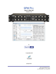
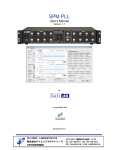
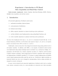
1
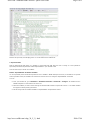
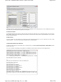
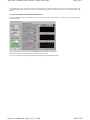
SOFT DB - SimulinkToSR Converter - Quick User Guide
Page 1 sur 5
Simulink to Signal Ranger
Converter
Quick User Guide
As its name indicates, the SimulinkToSR program links Matlab/Simulink files to the Signal Ranger DSP board. Doing so, DSP
programming is now possible for almost everyone.
First, the user needs Matlab/Real-Time Workshop to transform the Simulink model into C language.
Next, the generated files are sent through the SimulinkToSR Converter. It, then, generates a .out file that can be directly
implemented on the Signal Ranger board.
The required process time ranges from a few seconds to one minute depending on the system complexity.
After these steps have been completed, the SimulinkToSR interface allows you to communicate with the DSP board. It is then
possible to dynamically modify the parameters of your Simulink system and see its effect right away.
SimulinkToSR Converter Demonstration Video
Download the demo video that explains how to use the SimulinkToSR Converter software and shows the main functionalities.
Simulink Demo Video
Implementation Procedure
The following text describes the quick steps to implement a Simulink design on Signal Ranger DSP. However, the reading of the
user manual is recommended for better comprehension.
1.
2.
3.
4.
5.
6.
Configure your Simulink file
Design your system under Simulink
Predefine Simulink variables in MatLab workspace
Export variables
Build model with Real-Time Workshop
Convert and implement with SimulinkToSR interface
1. Configure Your Simulink File
To facilitate the setup of Simulink model, we provide you a simple example that is already configured to build a model with RealTime Workshop. We suggest you to begin your design from the example located in the "example" directory. It includes 4 files that
you can copy and rename as needed (except for grt_rtw_info_hook.m that have to keep the same name):
example.mdl: the pre-configured Simulink file
example_init.m: the file that initiates the sampling period (Ts) and other user variables
example_sim.m: the simulation file (optional)
grt_rtw_info_hook.m: Real-Time Workshop needs that file to generate the model in relation to the information specific to
the DSP. This file has to be present in the same directory as the Simulink file.
2. Design Your System Under Simulink
Use the Simulink help as needed if you are unfamiliar with the software.
Consult the list in Annexe B found in user manuel to know which blocks are supported by the current version of the SimulinkToSR
converter.
Note that input and output amplitudes in Simulink directly represent voltage amplitudes found on the board IOs.
Also, take note that the analogue dynamic ranges are normally of ±10 volts for the inputs and ±2 volts for the outputs. All values
over these ranges will saturate to their maximal value on the board.
http://www.softdb.com/a-dsp_30_2_3_1.html
2010-07-06
SOFT DB - SimulinkToSR Converter - Quick User Guide
Page 2 sur 5
When the Sample Time parameter is present in block parameters, assign its value to the same as the Fixed step size (Ts). When it
is mentioned beside the parameter, its value can alternatively be set to "-1" for inherited.
3. Predefine Simulink Variables in MatLab Workspace
Simulink parameters can be assigned a variable set in Matlab Workspace. To ease the process, use a M-file as an initiation file
before running the Simulink file. For now, you can look at example_init.m as an example.
http://www.softdb.com/a-dsp_30_2_3_1.html
2010-07-06
SOFT DB - SimulinkToSR Converter - Quick User Guide
Page 3 sur 5
Note that the previously used sampling period "Ts" is also defined in this initiation file.
4. Export Variables
With the Signal Ranger DSP board, it is possible to communicate with DSP while the code is running. It is then possible to
dynamically read and write parameters called "ExportedGlobal" in your Simulink model.
There are three ways to access user variables:
Declare "ExportedGlobal" Predefined Variables
You can dynamically access the Simulink parameters set to variables in Matlab workspace. However, the variables to be exported
must be specified. Indeed, all variables to be accessed in real-time have to be configured "ExportedGlobal" in Simulink.
To do so:
From your Simulink file, go to Simulation > Simulation Parameters > Advanced > Configure. All variables found in
MatLab workspace are enumerated in the Source list.
Select the variables you wish to access through the SimulinkToSR interface and press add to table>>. The added variables
then appear in Global (tunable) parameters.
Set the Storage class of all added variables to "ExportedGlobal" and press OK to confirm.
http://www.softdb.com/a-dsp_30_2_3_1.html
2010-07-06
SOFT DB - SimulinkToSR Converter - Quick User Guide
Page 4 sur 5
This works only if the variable is actually used somewhere as a parameter of your system. Moreover, some variables will be ignored
if Simulink does not allow a particular parameter to be dynamic.
Use Data Store Blocks
The Simulink blocks Data Store Memory, Data Store Read, and Data Store Write allow you to respectively declare, read, and write a
data variable. Simply set the RTW Storage Class parameter of the Data Store Memory block to "ExportedGlobal" to give dynamic
access through the interface.
Use Wire Probes
The use of a probe on a wire allows you to read (only) its value through the interface. To do so, right-click on the wire, select
"Signal Properties..." and set the RTW Storage Class parameter to "ExportedGlobal".
5. Build Model with Real-Time Workshop
To build the model with Real-Time Workshop from you Simulink file, go to Tools > Real-Time Workshop > Build Model (likewise
Ctrl+B or Build icon).
If no error is detected, the building process appears in the MatLab command window. Warnings are also displayed there.
http://www.softdb.com/a-dsp_30_2_3_1.html
2010-07-06
SOFT DB - SimulinkToSR Converter - Quick User Guide
Page 5 sur 5
A successful build of your Simulink system creates a new directory of name model_grt_rtw (model is your Simulink file name). The
files inside that directory will then be used by the SimulinkToSR Converter to implement the system onto a Signal Ranger DSP
board.
6. Convert and Implement with SimulinkToSR Interface
The SimulinkToSR Converter is responsible for converting the Real-Time model created in Simulink and for implementing the
system on the DSP.
Open the SimulinkToSR Converter, press the Convert button, and follow the instructions.
Within a few seconds, your Simulink Design should be ready to execute.
You can now interact with the Signal Ranger DSP board through the SimulinkToSR interface.
http://www.softdb.com/a-dsp_30_2_3_1.html
2010-07-06