1
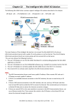
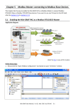
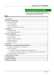
This manual only introduces the most basic application of MATLAB Solution Toolkit. For more detailed
information, please refer to I-8438/8838 User Manual.
Table of Contents
Introduction .......................................................................................................................................................... 2
System requirement.............................................................................................................................................. 2
Default IP setting .................................................................................................................................................. 2
OS & Firmware Version ...................................................................................................................................... 2
Chapter 1 Hardware connection ......................................................................................................................... 3
Chapter 2 Create a model using Simulink. ........................................................................................................ 4
Chapter 3 Build the program by RTW............................................................................................................... 7
Chapter 4 Program downloading & uploading ............................................................................................... 10
Addition Function for New Driver Version...................................................................................................... 13
8438/8838 Quick Start Manual, Version 1.0, 02/2004 -- 1
【 Introduction 】
MATLAB Solution Toolkit is a useful tool for you to construct your controller model. With it, you
can design your controller in MATLAB/Simulink, and convert it into an executable file easily and
quickly.
Note:
This manual is written based on MATLAB Solution Toolkit version 1.0.0.
【 System requirement 】
Hardware:
Module: ICPDAS I-8438/8838.
SRAM: 512KB
FLASH: 512KB
Software:
MATLAB 6.1 or 6.5
Simulink 4.1 or 5.0
Real-Time Workshop 4.1 or 5.0
Real-Time Workshop Embedded Coder 2.0 or 3.0
Stateflow and Stateflow Coder 4.1 or 5.0(opt.)
Notice:
Please make sure that MATLAB, Simulink, RTW and RTW Coder has been installed in your
system before you setup this toolkit. Otherwise it will not work properly.
【 Default IP setting 】
IP:
192.168.0.15
Gateway:
192.168.0.1
Mask:
255.255.0.0
If the default IP has a conflict with other devices in the network, users can change the IP setting of
the I-8438/8838 by the S-MMI buttons or from the GUI tool. You can refer to Appendix C. on
8438/8838 User Manual for detailed information.
【 OS & Firmware Version 】
OS:
MiniOS7 Ver. 2.00 build 001. (8E031103.img)
Firmware:
mat_load.exe Ver. 1.00
To update the OS or firmware on the I-8438/8838 embedded controller, please refer to Appendix
A. or B. on 8438/8838 User Manual respectively for detailed information.
8438/8838 Quick Start Manual, Version 1.0, 02/2004 -- 2
【 Chapter 1 Hardware connection 】
1.) Connect the network cable to the RJ-45 connector and a hub.
2.) Apply power (+Vs, GND) to I-8438/8838. The DC power can be the value from +10V to +30V.
3.) Check the 5 digits of the 7-segment LED. If the firmware is running, the IP address of the
I-8438/8838 will be displayed.
8438/8838 Quick Start Manual, Version 1.0, 02/2004 -- 3
【Chapter 2
Create a model using Simulink 】
1.) First start MATLAB and then click the Simulink icon
2.) Click
on the MATLAB toolbar.
on the Library Browser’s toolbar (Windows only). Simulink opens a new model
window, and then you can start to construct your own control model on the blank area of the
window.
3.) Copy a SYS_INIT, a DataToFile, an I-8024 and an I-8017H block from the System, AO and AI
library to the model window respectively.
4.) Double-click on the SYS_INIT block to open the dialog box. On the dialog box that appears,
8438/8838 Quick Start Manual, Version 1.0, 02/2004 -- 4
select the correct target hardware type from the field, Target Hardware Type. In this demo,
the target hardware is selected as I-8838.
5.) Double-click on the I-8024 block, and then the dialog box appears. To use channel 0 of I-8024
module, enter [0] in the field “Output Channel”. And select the slot as 2, Output Mode as
“Voltage Out”, Gain as 1 and Type of Value as “Floating”.
6.) Double-click on the block of I-8017H, enter [0] in the field “Channel”. And select the Voltage
range as “+/-1.25V”, Slot as 3 and Type of Value as “Floating”.
7.) Double click on the block of DataToFile, assign the Filename as “f001.mat”, and Decimation
as 1.
8438/8838 Quick Start Manual, Version 1.0, 02/2004 -- 5
8.) Copy a Sine Wave block to the model window from the Simulink\Sources library.
9.) Connect all the blocks as shown in the following figure.
8438/8838 Quick Start Manual, Version 1.0, 02/2004 -- 6
【 Chapter 3 Build the program by RTW 】
In this section, we will demonstrate you how to convert the control model created in the previous
section into an .exe by RTW.
1.) Open the Simulation Parameters dialog box by choosing Simulation parameters from the
Simulation menu.
2.) On the dialog box that displays, select Type as Fixed-step, Mode as Single Tasking
and Fixed step time as 0.002 in the field “Solver options”.
8438/8838 Quick Start Manual, Version 1.0, 02/2004 -- 7
3.) Then click the “Real-Time Workshop” tab and the panel changes. On the panel that
shows up, select Target configuration from the Category field. Then click the Browse
button to open the “System Target File Browser” window.
4.) On the System Target File Browser dialog, select the correct system target file from the
list and then click the OK button to close the dialog box. Here, we choose I_8xx8.tlc.
5.) And select the “ERT code generation options” (for MATLAB 6.1) or “ERT code
generation options (1)” (for MATLAB 6.5) in the Category field. Then check the
Terminate function required and Single output/update function options on the pane.
8438/8838 Quick Start Manual, Version 1.0, 02/2004 -- 8
6.) For MATLAB 6.5, you have to select “ERT code generation options (3)” from the
Category field. Then cancel the option Generate an example main program.
7.) When the above steps are done, save the model and click the Build button to start the
build process.
Note:
The name of the model cannot be over 4 characters. (This is due to the
limitation of Turbo C/C++ Compiler.)
8438/8838 Quick Start Manual, Version 1.0, 02/2004 -- 9
【 Chapter 4 Program downloading & uploading 】
Now we can download the .exe generated for testing. Please follow the steps:
1.) Enter gui8000 at the MATLAB prompt to start the GUI. Then specify the correct IP and Port
of the I-8438/8838 and press Connect. Note: The default listening port is 10000.
2.) After the connection is established, press Download to select the file and transfer it to the
I-8838 control system.
8438/8838 Quick Start Manual, Version 1.0, 02/2004 -- 10
3.) As soon as the download process is completed successfully, you can click Start to execute
the program.
4.) Then the pane changes like the following figure.
5.) After the time that you specified is up, press Upload button to collect the data for further
analysis. After the upload process is completed successfully, data will be saved as f001.mat,
which is the name you assigned in the DataToFile block.
8438/8838 Quick Start Manual, Version 1.0, 02/2004 -- 11
6.) Double-click on f001.mat and then enter plot(tcpdata(1, :), tcpdata(2, :)) at the MATLAB
prompt. The result would look like below:
Experiment Result
1.5
1
Amplitude (Volt)
0.5
0
-0.5
-1
-1.5
0
0.5
1
1.5
Time (second)
Note: To run this demo, what you need is that an I-8024 AO module and an I-8017H AI module
have been installed on slot 2 and 3 of the I-8838 respectively.
8438/8838 Quick Start Manual, Version 1.0, 02/2004 -- 12
Addition Function for New Driver Version
【New Function for Matlab Driver v1.1】
There are two new buttons -- “Auto” and “eAuto” provided in the GUI screen for RS-232 and
Ethernet interface separately. After users complete connection and download file to the matlab
controller, users can click “Auto” or “eAuto” button to execute the following continuous steps
automatically:
(1) “Run Program”
(2) “Upload when stop time is up”
(3) “Close GUI”
That will be more convenient for users to test the control algorithm during the development stage.
These two Auto button are showed as the following figure.
RS-232 Interface
Ethernet Interface
8438/8838 Quick Start Manual, Version 1.0, 02/2004 -- 13
The whole process for Auto button function is described as following ( Ethernet Interface
Example ):
After users complete the connection and download file to the matlab controller, users can click
Auto button in the GUI screen to execute the following steps:
(1) “Run Program”:
(2) “Upload when stop time is up”:
8438/8838 Quick Start Manual, Version 1.0, 02/2004 -- 14
(3) “Close GUI”:
8438/8838 Quick Start Manual, Version 1.0, 02/2004 -- 15