1
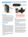
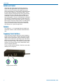
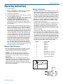
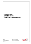
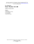
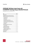
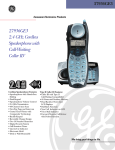
INSTRUCTION MANUAL
UCR100
UHF Multi-Frequency Compact Receiver
Fill in for your records:
Serial Number:
Purchase Date:
Rio Rancho, NM, USA
www.lectrosonics.com
UCR100
2
LECTROSONICS, INC.
Compact Receiver
Introduction
Thank you for selecting the Lectrosonics multi-frequency, UCR100 Receiver. The UCR100 is the result of
extensive engineering experience with the very latest
microprocessor advancements and technology.
The Lectrosonics 100 System Receiver and companion
transmitter are designed expressly for the most discriminating videographer and for other wireless applications
needing superior audio quality, flexible operation, and
outstanding durability. The compact size of the receiver
provides ease of integration with most any compact
video camera.
Table of Contents
Introduction..............................................................................................................................................................................................3
General Technical Description...............................................................................................................................................................4
Features.................................................................................................................................................................................................4
Dual Band Compandor..........................................................................................................................................................................4
UCR100 Block Diagram.....................................................................................................................................................................4
Pre-Emphasis/De-Emphasis..................................................................................................................................................................4
Controls & Functions..............................................................................................................................................................................5
Modulation LEDs....................................................................................................................................................................................5
Power ON/OFF Switch...........................................................................................................................................................................5
Power LED.............................................................................................................................................................................................5
RF LED..................................................................................................................................................................................................5
Audio Out Jack.......................................................................................................................................................................................5
Audio Level Control................................................................................................................................................................................6
Antenna..................................................................................................................................................................................................6
Frequency Select Switches....................................................................................................................................................................6
Operating Instructions............................................................................................................................................................................7
Indicator Quick Reference......................................................................................................................................................................7
Battery Instructions................................................................................................................................................................................7
Troubleshooting.......................................................................................................................................................................................8
Specifications and Features...................................................................................................................................................................9
Service and Repair................................................................................................................................................................................10
Returning Units for Repair...................................................................................................................................................................10
Rio Rancho, NM
3
UCR100
General Technical Description
Features
The multi-frequency UCR100 FM Receiver is designed
to operate with the Lectrosonics UM100 Transmitter and
features microprocessor control of 256 frequencies of
operation within each frequency block. Each block covers 25.5 MHz with 0.1 MHz frequency spacing. Any one
of ten different frequency blocks are factory available
from 537.6 MHz to 805.5 MHz (except 608 to 614 MHz).
The receiver’s unique microcontroller design provides
simple operation for audio level/limit LED monitoring, RF level LED monitoring, squelch, easy on-the-fly
frequency programming and low battery warning. The
UCR100 Receiver uses 20 kHz FM deviation for efficient use of the bandwidth and dual band companding
for clean quiet audio. The receiver operates on one 9
Volt alkaline battery for up to 8 hours and features a
blinking LED low battery indicator. The voltages are
internally regulated for stability. The receiver is housed
in a compact, rugged, lightweight aluminum enclosure.
The unit features a durable integral swing-aside battery
compartment door.
Dual Band Compandor
Traditionally, compandors have been a source of distortion in wireless microphone systems. The basic problem
with conventional systems is that the attack and decay
times are always a compromise. If the time constants
are fast, high frequency transients will not be distorted,
but this will cause low frequency distortion. If the time
constants are slower, low frequency audio distortion
will be low, but high frequency transients will then be
distorted.
The 100 system introduces the proven Lectrosonics approach to solving this basic problem, called “dual-band
companding.”
There are actually two separate compandors in the 100
system, one for high frequencies and one for low frequencies. A crossover network separates the frequency
bands at 1kHz with a 6dB per octave slope, followed
by separate high and low frequency compandors. The
attack and release times in the high frequency compandor are fast enough to keep high frequency transient distortion at a low level, and the low frequency
compandor uses slower time constants, reducing low
frequency distortion to well below that of a conventional
compandor.
Pre-Emphasis/De-Emphasis
The signal to noise ratio of the 100 system is extended
by utilizing pre-emphasis (HF boost) in the transmitter
and de-emphasis (HF roll off) in the receiver. Pre-emphasis and de-emphasis in an FM radio system usually
provides about a 10dB improvement in the signal to
noise ratio of the system, but the high frequency boost
in the transmitter must be removed in a purely complementary manner or else the frequency response of the
original audio signal will be altered.
The dual-band compandor in the 100 Series system
essentially provides a dynamic pre-emphasis/de-emphasis function with low distortion.
UCR100 Block Diagram
4
LECTROSONICS, INC.
Compact Receiver
Controls & Functions
Power LED
Power
ON/OFF
Switch
Antenna
Frequency Select Switches
(Under Door)
RF LED
Modulation LEDs
Audio LEVEL Control
Audio OUT Jack
Modulation LEDs
The two modulation LED’s indicate the modulation
(audio level) of the incoming signal and can be used for
proper adjustment of the transmitter’s mic or audio level.
The -20 LED glows when the transmitter modulation is
at a high enough level to produce a good audio signalto-noise ratio. It will normally flicker, or stay lit as you
speak into the microphone. The 0 dB lamp indicates
a “peak,” showing that the transmitter modulation is at
maximum. Constant lighting of the 0 dB LED indicates
that the audio gain in the transmitter may be set too
high. It is normal and desirable that you see an occasional flicker of the 0 dB lamp in typical use.
Power ON/OFF Switch
Turns the receiver on or off.
Power LED
The Power LED glows when the power switch is in the
ON position and the battery is good. The power LED
starts blinking when the battery is becoming exhausted
and needs replacement. If the LED does not light
up when the switch is turned on or during operation,
replace the battery. In normal operation a new alkaline
battery will operate the receiver approximately 5 hours
before the LED starts blinking and will continue operating for approximately another 3 hours before the LED
goes off. At that point the unit and the other LED’s
will continue operating for another hour or so but with
some degradation in performance. During the low battery blinking period the LED on time decreases as the
battery becomes depleated. See the chart in Battery
Instructions.
Battery Compartment
IMPORTANT! When the battery voltage drops
below 6 Volts, the power LED will remain off,
but the other 3 LEDs will light up and a rush of
audio noise and distortion will be heard as the
squelch opens. This condition is normal, and
is easily remedied by replacing the battery.
RF LED
Lights when the transmitter is turned on and the receiver has a strong RF signal. The RF LED will start
blinking when the RF carrier signal from the transmitter
becomes too weak to produce a clean audio signal.
The lamp will go out completely when the RF signal is
absent or extremely weak.
Audio Out Jack
The 3.5mm mini phone jack provides an audio output
that is controlled by the Audio LEVEL control on the
front panel. Generally, the Audio LEVEL control would
be set to provide the proper output level to match the
required level for your video camera or other equipment.
The 3.5mm mini jack will accommodate a mono plug
(tip & sleeve) or a stereo type jack (tip/ring & sleeve)
without harm to the unit. When using a pair of stereo
headphones the audio will be mono but will drive both
earphones in the correct (binaural) phase.
The output at this mini connector jack is designed to
also drive a standard impedance earphone, typically 30
Ohms (most common) and usually provides adequate
volume for setup and testing. The sound from a low
impedance ear phone (ie. 8 Ohms) will not be very loud
and may be distorted at higher listening levels.
The battery level is precision monitored by the internal
microprocessor which also drives the Power LED for
accurate battery condition.
Rio Rancho, NM
5
UCR100
Audio Level Control
Attenuates the audio output level of the receiver to
match the input requirements of the equipment with
which it is used. The 3.5mm Mini output jack on the
front panel provides an audio output at adjustable levels
for low or high impedance, unbalanced inputs. At the
extreme counter-clockwise position of the control knob,
the output level of the Mini jack will be -50dBV at full
modulation. In the fully clockwise position, the output
level will be 0dBV (1 Vrms) at full modulation. intermediate settings are sometimes necessary due to the variations in different input compressors and ALC (automatic
level control) circuits on various VCR’s and audio inputs.
The markings around the control knob are provided
simply as “memory markers;” they are not calibrated
with reference to a specific output level.
Antenna
The antenna is a 1/4 wavelength 50 ohm flexible nonremovable antenna made of durable sheathed bronze
wire.
Frequency Select Switches
These two rotary switches adjust the center frequency
of the carrier. The 1.6M is a coarse adjustment and the
100K is the fine adjustment. Each transmitter is factory
aligned at the center of its operating range. The default
position of the frequency select switches is in the center
of the transmitter’s range. The receiver and transmitter
switches must be set to the same number/letter combination for proper operation.
To gain access to these switches, slide the access door
sideways with a fingernail.
E
D
C
B
A
F 0 1
9 8 7
1.6M
2
6
3
4
5
E
D
C
B
A
F 0 1
9 8 7
2
6
3
4
5
100K
Frequency Select Switches
6
LECTROSONICS, INC.
Compact Receiver
Operating Instructions
1. Install the battery.
2. Set the “FREQUENCY” switches on the side panel
to match the switches on the Transmitter.
3. Connect the audio cable.
4. Set the front panel switch to ON. Check to see that
the red POWER LED lights up.
5. THIS IS PERHAPS THE MOST IMPORTANT STEP
IN THE SET UP PROCEDURE. Adjust the
transmitter “gain”. See your transmitter manual
(Operating Instructions section) for specific directions on the proper gain adjustment of your particular transmitter.
6. Adjust the output control according to the type of input on your equipment. The input levels on different
VCR’s and PA equipment vary, which may require
that you set the output LEVEL control in an intermediate position. Try different settings and listen to the
results. If the output of the receiver is too high, you
may hear distortion or a loss of the natural dynamics of the audio signal. If the output is too low, you
may hear steady noise (hiss) along with the audio.
The UCR100 output was designed to drive camera
line level inputs but can operate into camera MIC
inputs if the receiver output is reduced to prevent
Automatic Limiting Control “pumping” in the camera. The output signal level ranges from -50 dBV
with the output control fully counter clockwise to 0
dBV with the output control fully clockwise when the
transmitter signal is at full modulation.
Battery Instructions
The battery should be a 9 Volt alkaline or lithium, available almost everywhere. An alkaline battery will provide
up to 8 hours of operation and a lithium battery will
provide up to 20 hours of operation. Carbon zinc batteries, even if marked “heavy duty” will only provide about
2 hours of operation. Rechargeable batteries will only
operate the receiver for an hour or less. Make sure your
batteries are marked “alkaline” or “lithium.” Short
battery life is almost always caused by weak batteries
or batteries of the wrong type.
A steady “ON” LED corresponds to a fresh battery. The
LED will blink to indicate a low battery condition and
the need for a fresh battery. Continued use will further deplete the battery eventually causing the LED to
automatically turn itself off and remain off until a fresh
battery is installed.
To replace the battery, open the bottom battery door
cover with your thumb, rotate the door until it is perpendicular with the case and allow the battery to fall out of
the compartment into your hand. Observe the large and
small holes in the battery contact pad before inserting
a new battery. Insert the contact end of the battery first,
making sure the contacts are aligned with the holes in
the contact pad, and then swing the door closed. You
will feel it snap into place when it is fully closed.
Hours
Power LED
1
Solid On
2
Solid On
3
Solid On
RF - This LED lights up when the transmitter is turned
on. This indicates that the receiver is getting an adequate RF signal (carrier) from the transmitter.
4
Solid On
5
Solid On
POWER - This LED lights up when the receiver is
switched on. It indicates proper battery voltage when
the receiver is using a battery. See chart in Battery
Instructions.
6
Blinks 90% on, 10% off
7
Blinks 50% on, 50% off
8
Blinks 10% on, 90% off
9
Off (Replace battery)
Indicator Quick Reference
MODULATION - The “-20” LED lights up when an
audio signal is present at an adequate level to produce
a good signal to noise ratio. The “0dB” LED lights up
when the audio level is high and the signal is being
compressed in the transmitter. An extremely high audio
level may cause distortion.
1
2
Rio Rancho, NM
7
UCR100
Troubleshooting
Before going through the following chart, be sure that you have a good battery in the receiver.
The POWER LED should glow brightly.
SYMPTOM
POSSIBLE CAUSE
NO POWER LED 1)
2)
3)
4)
NO RF LED 1)
2)
3)
4)
5)
Receiver switch in “OFF” position
Dead or weak battery
Battery missing
Battery installed backwards
Transmitter not turned on
Transmitter battery dead
No microphone on the transmitter
Receiver antenna positioned incorrectly
Transmitter and Receiver on different frequencies
(FREQUENCY switches do not match transmitter switches)
RF LED ON BUT NO SOUND AND NO MODULATION LEDs
1) Transmitter audio level set to low
2) Transmitter microphone not connected
3) Microphone switch in “OFF” position
4) Check transmitter modulation LEDs for possible transmitter problem
MODULATION LED’s ON BUT NO SOUND 1) Receiver LEVEL control turned down
2) Audio cable disconnected
3) Recorder or sound system off or not properly adjusted
DISTORTED SOUND
1) Transmitter Audio Level set too high
(check mod lamps on Transmitter)
2) Weak battery
SHORT RANGE
1) Transmitter or receiver antenna not clear of obstructions
HISS AND NOISE -- AUDIBLE DROPOUTS
1)
2)
3)
4)
Transmitter gain (audio level) far too low.
Receiver antenna obstructed or damaged.
Transmitter antenna obstructed or damaged.
Operating range too great.
HISS AND NOISE – PUMPING
1) Camera or recorder has automatic level control. Use line level input
on camera or recorder. If there is only a mic input, reduce the receiver
output to near minimum.
8
LECTROSONICS, INC.
Compact Receiver
Specifications and Features
Available frequencies:
Number of frequencies per block: Channel spacing: Frequency control: Sensitivity: Signal/Noise ratio: Squelch quieting: AM rejection: Modulation acceptance: Spurious rejection: Third order intercept: Frequency response: Distortion:
Audio output: Antenna: Front panel controls: LED Indicators: Battery Life: Power consumption: Weight: Size: 537.6 to 608 MHz, 614 to 691.1 MHz
(Blocks 21 through 26)
Each unit operates on a single block.
256 in 100 kHz steps
100 kHz
Crystal Controlled Phase Locked Loop
1 uv (20 dB SINAD)
105 dB (system)
90 dB
50 dB, 10 uv to 100 mv
+/-20 kHz
Greater than 70 dB
0 dBm
50 Hz to 18 kHz, (±2 db)
1% max at 50% modulation (system)
0 dBv (1 Vrms) UNBALANCED into 600 ohms
1/4 wave vertical (fixed)
Single knob controls Audio Output Level
Power (red), RF (green), Level (green),
Limit (red)
Single 9V Alkaline Battery for approximately
8 hours operation.
60 ma.
7.3 oz with battery
3.6 x 2.4 x 0.8 inches (housing only, belt clip and
knob extend beyond the housing.)
Specifications subject to change without notice.
Rio Rancho, NM
9
UCR100
Service and Repair
If your system malfunctions, you should attempt to correct or isolate the trouble before concluding that the equipment
needs repair. Make sure you have followed the setup procedure and operating instructions. Check the interconnecting cables and then go through the Troubleshooting section in this manual.
We strongly recommend that you do not try to repair the equipment yourself and do not have the local repair shop
attempt anything other than the simplest repair. If the repair is more complicated than a broken wire or loose connection, send the unit to the factory for repair and service. Don’t attempt to adjust any controls inside the units. Once
set at the factory, the various controls and trimmers do not drift with age or vibration and never require readjustment.
There are no adjustments inside that will make a malfunctioning unit start working.
Lectrosonics’ Service Department is equipped and staffed to quickly repair your equipment. In warranty repairs are
made at no charge in accordance with the terms of the warranty. Out-of-warranty repairs are charged at a modest flat
rate plus parts and shipping. Since it takes almost as much time and effort to determine what is wrong as it does to
make the repair, there is a charge for an exact quotation. We will be happy to quote approximate charges by phone for
out-of-warranty repairs.
Returning Units for Repair
For timely service, please follow the steps below:
A. DO NOT return equipment to the factory for repair without first contacting us by email or by phone. We need
to know the nature of the problem, the model number and the serial number of the equipment. We also need a
phone number where you can be reached 8 A.M. to 4 P.M. (U.S. Mountain Standard Time).
B. After receiving your request, we will issue you a return authorization number (R.A.). This number will help speed
your repair through our receiving and repair departments. The return authorization number must be clearly shown
on the outside of the shipping container.
C. Pack the equipment carefully and ship to us, shipping costs prepaid. If necessary, we can provide you with the
proper packing materials. UPS is usually the best way to ship the units. Heavy units should be “double-boxed” for
safe transport.
D. We also strongly recommend that you insure the equipment, since we cannot be responsible for loss of or damage to equipment that you ship. Of course, we insure the equipment when we ship it back to you.
Lectrosonics USA:
Mailing address:
Shipping address:
Lectrosonics, Inc.
Lectrosonics, Inc.
PO Box 15900
581 Laser Rd.
Rio Rancho, NM 87174
Rio Rancho, NM 87124
USAUSA
Telephone:
(505) 892-4501
(800) 821-1121 Toll-free
(505) 892-6243 Fax
Web:E-mail:
www.lectrosonics.com
[email protected]
Lectrosonics Canada:
Mailing Address:Telephone:E-mail:
49 Spadina Avenue,
(416) 596-2202
Sales: [email protected]
Suite 303A
(877) 753-2876 Toll-free
Service: [email protected]
Toronto, Ontario M5V 2J1
(877-7LECTRO)
(416) 596-6648 Fax
10
LECTROSONICS, INC.
Compact Receiver
Rio Rancho, NM
11
LIMITED ONE YEAR WARRANTY
The equipment is warranted for one year from date of purchase against defects in
materials or workmanship provided it was purchased from an authorized dealer. This
warranty does not cover equipment which has been abused or damaged by careless
handling or shipping. This warranty does not apply to used or demonstrator equipment.
Should any defect develop, Lectrosonics, Inc. will, at our option, repair or replace any
defective parts without charge for either parts or labor. If Lectrosonics, Inc. cannot
correct the defect in your equipment, it will be replaced at no charge with a similar new
item. Lectrosonics, Inc. will pay for the cost of returning your equipment to you.
This warranty applies only to items returned to Lectrosonics, Inc. or an authorized
dealer, shipping costs prepaid, within one year from the date of purchase.
This Limited Warranty is governed by the laws of the State of New Mexico. It states the
entire liablility of Lectrosonics Inc. and the entire remedy of the purchaser for any
breach of warranty as outlined above. NEITHER LECTROSONICS, INC. NOR
ANYONE INVOLVED IN THE PRODUCTION OR DELIVERY OF THE EQUIPMENT
SHALL BE LIABLE FOR ANY INDIRECT, SPECIAL, PUNITIVE, CONSEQUENTIAL,
OR INCIDENTAL DAMAGES ARISING OUT OF THE USE OR INABILITY TO USE
THIS EQUIPMENT EVEN IF LECTROSONICS, INC. HAS BEEN ADVISED OF THE
POSSIBILITY OF SUCH DAMAGES. IN NO EVENT SHALL THE LIABILITY OF
LECTROSONICS, INC. EXCEED THE PURCHASE PRICE OF ANY DEFECTIVE
EQUIPMENT.
This warranty gives you specific legal rights. You may have additional legal rights which
vary from state to state.
581 Laser Road NE • Rio Rancho, NM 87124 USA • www.lectrosonics.com
(505) 892-4501 • (800) 821-1121 • fax (505) 892-6243 • [email protected]
ucr100man.indd
5 April 2011