1
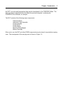
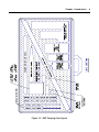
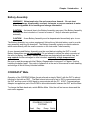
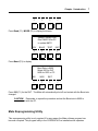
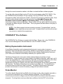
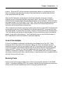
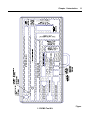
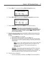
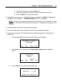
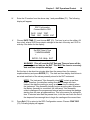
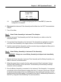
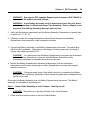
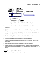
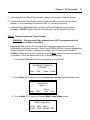
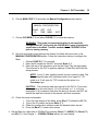
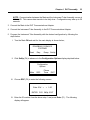
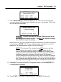
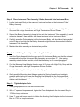
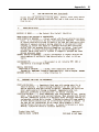
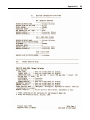
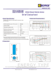
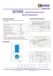
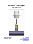
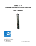
DCMS™ DOWNHOLE CORROSION MONITORING SYSTEM USER MANUAL Rohrback Cosasco Systems, Inc. 11841 East Smith Avenue Santa Fe Springs, CA 90670 Tel: +1 (562) 949-0123 Fax: +1 (562) 949-3065 Email: [email protected] Web: http://www.rohrbackcosasco.com P/N 724000-Manual Rev G ©1991 - 2006 Rohrback Cosasco Systems, Inc. All rights reserved. Corrosometer®, Corrdata®, Corrdata Plus® and DCMS are trademarks of Rohrback Cosasco Systems, Inc. No part of this manual may be reproduced or transmitted in any form or by any means, electronic or mechanical, including photocopying and recording, for any purpose, without the express written permission of Rohrback Cosasco Systems, Inc. ii Table of Contents Chapter 1 Introduction ............................................................................................................ 1 Downhole Corrosion Monitoring System (DCMS) .................................................................. 1 Downhole Tool (DHT) ............................................................................................................ 1 Instrument Body..................................................................................................................... 5 Instrument Tube Assembly .................................................................................................... 5 Probe Assembly ..................................................................................................................... 5 Probe Shield .......................................................................................................................... 5 Probe Adapter........................................................................................................................ 5 Mounting Head Adapter ......................................................................................................... 5 Battery Assembly ................................................................................................................... 6 CORRDATA® Mate ................................................................................................................ 6 Mate Reprogramming Utility................................................................................................... 7 CORRDATA® Plus Software .................................................................................................. 8 Battery Depassivation Instrument .......................................................................................... 8 Probe Monitor ........................................................................................................................ 8 Cross-Flow Adapter ............................................................................................................... 9 Running Tools ........................................................................................................................ 9 Chapter 2 Specification......................................................................................................... 13 Downhole Tool Specification ................................................................................................ 13 Battery Assembly Specification............................................................................................ 14 DHT Operating Duration: ..................................................................................................... 14 Chapter 3 DHT Operational Pretest...................................................................................... 15 Assembly Sequence ............................................................................................................ 15 Disassembly Sequence........................................................................................................ 22 Chapter 4 DHT Assembly...................................................................................................... 25 Recommended Tools ........................................................................................................... 25 Assembly Sequence ............................................................................................................ 26 Disassembly Sequence........................................................................................................ 39 Appendix A Lithium Thionyl Chloride Batteries: Handling, Storage, MSDS .................... 43 Emergency Procedures........................................................................................................ 43 Emergency Conditions ......................................................................................................... 43 Causes of Hazardous Conditions-........................................................................................ 43 Electrical and Physical ......................................................................................................... 43 Safe Storage ........................................................................................................................ 44 Safe Incoming Inspection..................................................................................................... 44 Safe Testing......................................................................................................................... 44 Safe Transportation.............................................................................................................. 45 Safe Disposal....................................................................................................................... 46 iii Figures and Drawings Figure Figure 1.1 Figure 1.2 Figure 1.3 Figure 4.1 Figure 4.2 Figure 4.3 Figure 4.4 Page Cross-Sectional View of Fully Assembled DHT ....................................................... 2 DHT Carrying Case Layout...................................................................................... 4 DCMS Tool Kit....................................................................................................... 11 DHT Assembly Drawing......................................................................................... 26 Mounting Head Adapter O-Ring and Back-Up Ring Placement............................. 27 Probe Adapter O-Ring and Back-Up Ring Placement ........................................... 28 Probe Assembly Attached to Probe Adapter ......................................................... 30 1 Chapter 1 Introduction Downhole Corrosion Monitoring System (DCMS) The RCS Downhole Corrosion Monitoring System (DCMS) is the only system which provides continuous corrosion history of downhole tubing. The DCMS is a specific adaptation of the CORRDATA system for the severe downhole environment and provides an accurate means of determining corrosion rates at various depths within a well bore. The corrosion data provided by the DCMS permits quantitative evaluation of inhibitors and treatment regimes for the most cost-effective results. The DCMS consists of the following major components: Downhole Tool (DHT) CORRDATA Mate CORRDATA® Plus Software DHT Communications Adapter Battery Depassivation Instrument Probe Monitor Instrument Cross-Flow Adapter (Customer Supplied) Downhole Tool (DHT) The Downhole Tool (DHT) is a tubular electronic instrument, as shown in Figure 1.1, that is designed to be run and retrieved by wire line operation into the production tubing of a well for an extended period of time. The DHT uses a CORROSOMETER Probe Element to determine the rate of metal loss within the well bore. The Probe Element is electrically isolated from the rest of the tool and the well bore to prevent galvanic corrosion from influencing measurement data. The Probe Element is made from the same or similar type material as the well bore being monitored. The DHT itself with 1.25" diameter provides a very small percentage restriction in the pipe. The Cross-Flow adapter and tubing lock from which the DHT is suspended provides the main flow restriction of approximately 50% area on the pipe. An RTD temperature sensor, internal to the DHT provides temperature data. The DHT electronically measures the Probe Assembly and temperature sensor at user programmable intervals, and stores each reading in nonvolatile memory. Upon retrieval of Chapter 1 Introduction Figure 1.1 Cross-Sectional View of Fully Assembled DHT 2 Chapter 1 Introduction 3 the DHT, corrosion and temperature data may be downloaded to the CORRDATA Mate. The data may then be transferred from the Mate to a personal computer, containing the CORRDATA Plus Software, for analysis. The DHT consists of the following major components: Instrument Body Instrument Tube Assembly Probe Assembly Probe Shield Probe Adapter Mounting Head Adapter Battery Assembly When not in use, the DHT and other DCMS components may be stored in a protective carrying case. The arrangement of the carrying case is shown in Figure 1.2. Chapter 1 Introduction Figure 1.2 DHT Carrying Case Layout 4 Chapter 1 Introduction 5 Instrument Body The Instrument Body is normally a 17-4 PH ferritic stainless steel tube designed to contain and protect the main components of the DHT from the hostile environment of the well. Instrument Tube Assembly The Instrument Tube Assembly is a stainless steel tube approximately 1.25"dia. x 18"L. It has a large probe connector at one end and a small battery connector at the other end. The Instrument Tube Assembly contains electronic circuitry which accurately measures the Probe Element and internal temperature sensor. Probe Assembly The Probe Assembly is a specially modified CORROSOMETER probe. The Probe Assembly contains an element made from the same or similar material as the well bore. A reference element of the same material is contained within the Probe Assembly to compensate for resistance changes due to temperature. Since the Probe Assembly is very delicate, care must be taken to avoid damage. WARNING! The tip of the Probe Assembly is extremely sharp. Handle with care to avoid injury or damage. Probe Shield The Probe Shield is used to protect the Probe Assembly from damage and debris in the well, and provide as smooth a flow as possible over the Probe Element surface. The Probe Shield slides over the Probe Assembly and is threaded onto the Probe Adapter. Probe Adapter The Probe Adapter is a fitting used to adapt the Probe Assembly to the Instrument Body. Mounting Head Adapter The Mounting Head Adapter is a fitting equipped with a 5/8" API sucker rod connection (Spec. 11B). The Mounting Head Adapter is used to attach the Cross-Flow Adapter to the Instrument Body. Chapter 1 Introduction 6 Battery Assembly WARNING! Violent explosion, fire and severe burn hazards . Do not short circuit, recharge, disassemble, overheat, incinerate, or expose contents to water. Refer to Appendix A for handling and storage information. CAUTION! An internal fuse in the Battery Assembly may open if the Battery Assembly terminals are short circuited or if current in excess of 1 Amp is otherwise produced externally. CAUTION! A new Battery Assembly must be depassivated immediately prior to use. The Battery Assembly is a custom engineered, lithium thionyl chloride battery used to provide easy assembly and long life downhole. The Battery Assembly contains a coaxial connector which mates directly with the small connector on the Instrument Tube Assembly. A new, depassivated Battery Assembly must be used before installing the DHT in a well. Battery Assemblies are not rechargeable! Do not attempt to defeat the safety connector at the end of a Battery Assembly. Battery Assemblies are protected with an internal fuse, but may explode if either recharged or short circuited, especially at high temperatures! Be sure to read the paragraph titled “Battery Depassivation Instrument” in Chapter 3 before installing the battery pack. Also refer to Appendix A at the end of this manual for safe handling and storage of lithium thionyl chloride batteries. CORRDATA® Mate Operation of the CORRDATA Mate (herein referred as simply “Mate”) with the DHT is almost identical to that with an RDC. The Mate’s baud rate must be set to 300 to communicate with the DHT and then reset to 9600 baud to communicate with the PC. A DHT Communications Adapter is supplied as part of the DCMS to allow data transfer between the DHT and the Mate. To change the Mate baud rate, switch ON the Mate. After the self test screen clears and the main menu appears. ROHRBACK COSASCO SYSTEMS Read Disp Dump SetUp Chapter 1 Introduction ¿ ¿ ¿ ¿ F1 F2 F3 F4 7 Press Read (F1); MODE (F2) to display the screen. Special Testing Code Run PMATE from PC to update MATE REV BAUD TEST EXIT ¿ ¿ ¿ ¿ F1 F2 F3 F4 Press Baud (F2) to display. Baud Rate is 9600 Select 300 for DHT 9600 for RDC or PC 300 9600 EXIT ¿ ¿ ¿ ¿ F1 F2 F3 F4 Press 300 (F1) for the DHT. The Mate will automatically shut off and restart with the Baud rate changed. CAUTION! Remember to repeat the procedure and set the Baud rate to 9600 to communicate with the PC. Mate Reprogramming Utility This reprogramming utility is only required if for any reason the Mate software program has become corrupted. This program utility in the CORRDATA Plus installation disk operates Chapter 1 Introduction 8 through the normal connection cables to the Mate to reload the Mate software program. To run this utility, plug the Mate into the PC with the serial adapter cable (P/N 748063). Run the CORRDATA Plus Installation CD by inserting it into the CD-ROM. Click the “Mate Programming Utility“ link and choose “Install”. Follow the PC prompts to install the utility. Once the utility is successfully installed, run the application from Start Æ All Programs Æ Rohrback Cosasco Systems Æ Mate Programming Utility. The PC will display the instructions of keys to press on the Mate. In most cases, the user will be able to successfully re-program the Mate using the “Quick Mode.” This re-programs the Mate without losing any of the stored data. NOTE: If the Mate program has been severely corrupted, “Complete Mode” must be run. In this case, repeat above steps and select “Complete Mode” and follow the wizard instructions to complete the programming. CORRDATA® Plus Software The CORRDATA Plus Software is supplied with the Mate. Please refer to the CORRDATA Plus Corrosion Management Solutions Manual on the CD-ROM for details. Battery Depassivation Instrument A new Battery Assembly must be depassivated just prior to use in order to remove a passivation layer that naturally inhibits energy transfer from the Battery Assembly to the DHT electronics. The depassivation procedure requires that a Battery Depassivation Instrument (P/N 724023) be connected to the Battery Assembly for a period of time. The Battery Depassivation Instrument initially loads the Battery Assembly to begin depassivation. It then monitors the output voltage of the Battery Assembly, under load, until it rises to an acceptable level. While the Battery Assembly is being depassivated a yellow lamp on top of the Battery Depassivation Instrument will remain illuminated. When the depassivation process is complete, the yellow lamp will extinguish and a flashing green lamp will illuminate. The Battery Assembly is now ready for immediate use. The depassivation procedure should not last more than 60 minutes. The Battery Depassivation Instrument provides test terminals to monitor the battery voltage with an external voltmeter. Probe Monitor To confirm that the Downhole Tool (DHT) is functioning correctly, after complete assembly, a non-intrusive Probe Monitor (P/N 724024) has been designed. The Probe Monitor continuously monitors the voltage across the Probe Element and detects when the probe is energized. Counting these events provides high confidence that the DHT is functioning Chapter 1 Introduction 9 properly. Since the DHT performs periodic measurements based on a programmed cycle time, a countdown timer has been provided in the Probe Monitor to indicate when the next probe measurement will be made. When the DHT performs a measurement of the Probe Assembly, the probe is actually energized for two consecutive intervals, each lasting about 3 seconds. There is about 5 seconds duration between these intervals where the probe is not energized. The two intervals have been named CYCLE ONE and CYCLE TWO. The Probe Monitor indicates which cycle is presently occurring during the measurement. Both cycles must be measured before the Instrument will decrement the countdown timer. The countdown timer should be accurate to within a few seconds of actual DHT measurements as long as the cycle time for the Probe Monitor is the same as the DHT configured cycle time. The Probe Monitor is powered by a 9V battery. Alkaline or lithium batteries are recommended. The Probe Monitor will operate for approximately 24 hours continuously with a fresh alkaline battery (longer with a lithium battery). The Probe Monitor may not store the total number of DHT measurements made if the battery is completely depleted. Cross-Flow Adapter A Cross-Flow Adapter is attached to the Mounting Head Adapter end of the DHT. While holding the DHT in the center of the production tubing, the Cross-Flow Adapter serves to transfer the well bore flow from the outside of the DHT to the inside of the lock mandrel. The Cross-Flow Adapter must minimize pressure drop as well as provide the strength required to support the DHT. Typically, a Cross-Flow Adapter will drop only a few psi. The DHT is capable of mounting on a variety of lock systems. The lock mandrel and Cross-Flow Adapter are usually customer specific items, and are chosen or manufactured to be compatible with the wire line running tools to be used. Running Tools Running Tools and running procedures are critical to the successful operation of the DCMS system. Consultations between RCS, the customer, and the wire line company are required to ensure correct tools are available and correct running procedures are used. Chapter 1 Introduction 10 RCS offers a custom DCMS Tool Kit (P/N: 724005) to provide for the complete assembly and disassembly of the DHT. In addition to mechanical tools, four custom electronic instruments are included which are necessary to setup and monitor the DHT. The contents and layout of the DCMS’ Tool Kit are shown in Figure 1.3. Chapter 1 Introduction 11 Figure 1.3 DCMS Tool Kit Chapter 1 Introduction 12 13 Chapter 2 Specification Downhole Tool Specification Environment: Oil, Gas, Water production (Sweet or Sour Service subject to running tool specifications) Shock: 30 G’s Max Random Vibration: 30 to 300 Hz at 2.22 G2/Hz, 25 G rms Temperature: 285°F (140°C) maximum Pressure: 10,000 psi (69 MPa) maximum Flow Velocity: 90 feet per second maximum gas flow, 20 feet per second maximum liquid flow Body Material (Standard): UNS S17400 (17-4 S.S.) Conforming to NACE MR0175 CORROSOMETER Probe Assembly: Repeatability: ± 0.5% of Span Resolution: 0.1% of Span Temperature Sensor: Accuracy: ± 3°F Repeatability: ± 3°F Resolution: 0.1°F Memory Capacity: 1024 Measurements via CORRDATA Mate Measurement Intervals (programmable): 15 min., 30 min., 1 hr., 2 hr., 4 hr. Thread Attachment: 5/8" API Sucker Rod Connection Spec. 11B 14 Battery Assembly Specification RCS Part No.: 724088 Type: Lithium Thionyl Chloride Li Weight: 7.4 grams Voltage: 7.32 Voc (open circuit) Operating Temp: +20 °C to +180 °C Shock: 250 G’s Max at 150 °C Random Vibration: 30 to 300 Hz at 2.22 G2/Hz 25 Grms DHT Operating Duration: DHT Programmed Measurement Interval Approximate Operating Time (with a new Battery Assembly) 1 hr. 60 days 2 hr. 65 days 4 hr. 70 days 15 Chapter 3 DHT Operational Pretest The user may wish to determine that the Instrument Tube Assembly, Probe Assembly and Battery Assembly are operational before complete assembly of the DHT. A Pretest may be performed by following the steps below: WARNING! Always perform a Pretest at “room temperature”. Do not perform a Pretest at temperatures above 125 °F. It is highly recommended that new batteries are used on the DHT Communications Adaptor and the Probe Monitoring Tool before a new session. Assembly Sequence Step 1: Depassivate New Battery Assembly: WARNING! Use only the RCS supplied Depassivation Instrument (P/N 724023) to depassivate the battery and verify voltage. NOTE: The Battery Depassivation Instrument is used in this step. It automatically monitors the Battery Assembly output voltage while applying a nominal load. The Battery Depassivation Instrument will remove the load when the output voltage of the Battery Assembly reaches a value which indicates that the passivation has been adequately removed. WARNING! A new Battery Assembly must be depassivated less than four hours prior to connecting it with the Instrument Tube Assembly. Refer to Chapter 1 and Appendix A for Battery Assembly warnings and cautions. 1. Verify that the ambient temperature and the Battery Assembly Temperature is greater than or equal to 21 °C (70 °F). 2. If desired, monitor the voltage between the red and black terminals on the Battery Depassivation Instrument with a high impedance voltmeter. 3. Connect the Battery Assembly to the Battery Depassivation Instrument. The yellow lamp will illuminate immediately. Depending on the degree of battery passivation, the battery voltage may initially drop below 5.0V. Chapter 3 DHT Operational Pretest 16 CAUTION! If no status lamps on the Battery Depassivation Instrument are illuminated while the Battery Assembly is connected, then the Battery Assembly is either excessively passivated or depleated and should not be used. 4. Monitor the Battery Depassivation Instrument status lamps until the yellow lamp extinguishes and the green lamp begins to flash. Depassivation may take from several minutes to one hour. CAUTION! If the green lamp doesn’t flash within one hour of connecting the Battery Assembly, then the Battery Assembly is either excessively passivated or depleated and should not be used. 5. Disconnect the Battery Assembly from the Battery Depassivation Instrument. The Battery Assembly is now ready for immediate use. Step 2: Program Instrument Tube Assembly. WARNING! The Instrument Tube Assembly must NOT be programmed while connected to the Battery Assembly. 1. Program the Mate from the PC with the probe configuration required or set up the configuration on the Mate manually. Refer to the CORRDATA Plus Corrosion Management Solutions Manual for details on setting up the Mate via PC (It is the recommended to CLEAR the Mate memory prior to programming, this WILL erase all previously saved data on the Mate). Follow the steps below to set up the Mate manually. I. Turn the Mate ON and wait for the main display is shown below; ROHRBACK COSASCO SYSTEMS Read Disp Dump SetUp II. Click SetUp (F4) to advance to the Configuration Options display depicted below: Configuration Options Mate RDC Phone Timer EXIT Chapter 3 DHT Operational Pretest 17 III. Choose Mate (F1) to enter the following Mate Configuration screen: Mate Configuration AUTO MAN NEW CONF CONF PROBE EXIT IV. Choose MAN CONF (F2) and enter the Manual Configuration screen below: MANUAL CONFIGURATION CONF ID SET TIME CLR MEM EXIT V. Choose CLR MEM (F3) and select CLEAR (F1) to clear the memory. WARNING! This is the recommended method to successfully configure the DHT. Performing the CLEAR WILL erase all previously saved data on the Mate. Transfer needed data to CORRDATA Plus prior to erasing memory. VI. Once the previously stored settings are cleared, the Mate will return back to the MANUAL CONFIGURATION screen. Follow the instructions below to configure the Mate. i. Choose CONF ID (F1) to proceed. ii. Enter the ID number for the DHT and press Enter (F1). iii. Enter the rest of the information such as the Probe Tag, the appropriate Time Interval for the DHT to perform readings, Probe Alloy and finish the setup process. NOTE: A one (1) hour reading interval is most commonly used. The Probe Assembly type is D (cylindrical) with a 5 mil span for “T10" model or a 10 mil span for “T20" model and the probe is a Corrotemp type. CAUTION! The minimum read time interval for the DHT is 15 minutes. User may set up the read time to 15 or 30 minutes, or 1, 2, or 4 hour increments. If an increment other than the above is chosen, the DHT will default the read time interval to the nearest valid time increment. VII. Check the setup configuration I. From the main display of the Mate, press Disp (F2) followed by ID (F2). Chapter 3 DHT Operational Pretest 18 II. Type in the ID number and press Enter (F1). III. Check the configuration values to make the desired values are set. IV. Press the More F(1) check other values. 2. Set the Mate for a data rate of 300 BAUD by pressing: Read (F1); MODE (F2); Baud (F2); and 300 (F1). See Chapter 1 – CORRDATA Mate section for more details. NOTE: Communication between the Mate and the Instrument Tube Assembly occurs at 300 BAUD. This causes data transfer to be fairly slow. Configuration may take up to 30 seconds. 3. Connect the Mate to the DHT Communications Adapter. 4. Connect the Instrument Tube Assembly to the DHT Communications Adapter. 5. Program the Instrument Tube Assembly with the desired configuration by following the steps below: I. Turn the Mate ON and wait for the main display is shown below; ROHRBACK COSASCO SYSTEMS Read II. Disp Dump SetUp Click SetUp (F4) to advance to the Configuration Options display depicted below: Configuration Options Mate III. RDC Phone Timer EXIT Choose RDC (F2) to enter the following screen: Enter ID # > < 1-50 ENTER CLR BkSp EXIT Chapter 3 DHT Operational Pretest IV. 19 Enter the ID number from the above step 1 and press Enter (F1). The following display will appear. RDC Configuration Connect Mate to RDC DATE CONF TEST TIME RDC MODE EXIT V. Choose DATE TIME (F1) and choose SET (F2). The hour is set on the military 24 hour clock, where 00.00 hours depict midnight at the start of the day and 12:00 is mid-day. See below for the display: Set RDC Date & Time YYMMDDHHMMSS > < ENTER CLR BkSp EXIT WARNING! This will reset the DHT Date and Time and erase all the previously stored data on the DHT. This MUST be done to accurately date and time stamp the readings. Set the time to be about ten minutes later than the present time (for reasons explained below) and press ENTER (F1). The date and time display that follows is an actual read-back of the values presently stored in the DHT Instrument. NOTE: The Instrument Tube Assembly does NOT contain a real-time clock. Therefore, the date/time setting does NOT change with time. Instead, the date/time setting is purely a reference time to denote when the Instrument Tube Assembly actually begins recording data. Whenever the Battery Assembly is connected, the Instrument Tube Assembly collects readings at the programmed interval and time stamp the readings starting from the user programmed time. This is the reason for setting the time 10 minutes later than the present time, to let the user finish the rest of the steps and have enough time to begin the readings at the current time. VI. Press Exit (F4) to return to the RDC Configuration screen. Choose CONF RDC (F2). Following display will appear: Chapter 3 DHT Operational Pretest 20 Connect Mate to RDC - CO SET START MUX VII. NEW PROBE EXIT Press START (F1) to begin configuring the DHT. Press EXIT (F4) when the configuration is complete. 6. Disconnect the Instrument Tube Assembly and the Mate from the DHT Communications Adapter. 7. Turn off the Mate. Step 3: Attach Probe Assembly to Instrument Tube Adapter. 1. Lay the Instrument Tube Assembly and the Probe Assembly on a table or other flat, horizontal surface. 2. Connect the Probe Assembly to the Instrument Tube Assembly by mating the connector end of the Probe Assembly to the large connector on the Instrument Tube Assembly. 3. Carefully rotate the Probe Assembly until the connector keys are aligned and then push in the connectors together as far as possible. Step 4: Attach Battery Assembly to Instrument Tube Assembly. WARNING! Always use a new Battery Assembly and depassivate immediately before use. 1. Maintain the Probe Assembly, Instrument Tube Assembly and the Battery Assembly on a table or other flat, horizontal surface. 2. When the present time is equal to the time value entered in Step 5 (sub-step V) above, slide the small connector on the Instrument Tube Assembly into the Battery Assembly connector as far as possible. 3. Once the Battery Assembly is connected to the Instrument Tube Assembly, it is energized and will take the first Probe Element reading after about 12 minutes, 30 seconds. This will be the first stored reading in the non-volatile memory. Next reading will commence at the specified interval from this reading. It is possible for the user to validate the performance of the DHT by using the Probe Monitoring Tool (see step below). Chapter 3 DHT Operational Pretest 21 CAUTION! DHT can store a maximum of 1024 readings on its non-volatile memory. Once this limit is met, the DHT will not store anymore readings. Step 5: Test DHT Operation with Probe Monitor. Use the DHT Probe Monitor (P/N 724024) as described below to determine if the DHT is operational. NOTE: Regardless of the preprogrammed time setting, the DHT will take the first Probe Element reading about 12 minutes, 30 seconds after the Battery Assembly is connected to the Instrument Tube Assembly. This allows sufficient time for final assembly of the DHT and attachment of the Probe Monitor to catch the first reading made by the Instrument Tube Assembly. 1. Connect the RED lead to the exposed metal surface of the Probe Element near the Probe Wrench-Flats. 2. Connect the BLACK lead to the exposed metal surface of the Probe Element near the probe tip. The best sensitivity is achieved when the BLACK and RED leads are spaced as far apart as possible while making positive electrical contact to the Probe Element. 3. Press the ON key. Wait for the display prompt “Ready to Test DHT” 4. Press the CONFIG key. If the cycle time, which is expressed in minutes, is correct, proceed to step 6. 5. If the cycle time is not correct, press the EDIT key followed by the UP and DOWN arrow keys to correctly program the cycle time. When the cycle time is correct, press the EDIT key again to store the reading (the old value will be lost) or press the CONFIG key to abort (no changes will occur). NOTE: It is suggest setting the cycle time with few extra minutes compared to the actual reading interval to avoid and erroneous timeouts. 6. Press the DISPLAY key to determine how many measurements were made. This will be zero for initial use. 7. Press the MEAS key to initiate monitoring the Probe Element. It may be necessary to let the Probe Monitor warm up for a couple of minutes before performing measurements. The countdown timer will be activated, counting from the cycle time down toward zero. If zero is reached before a Probe Element measurement is detected, a time-out message is displayed. Chapter 3 DHT Operational Pretest 22 8. Press any key to stop the measurement process. If the MEAS key is pressed again, the number of measurements will be initialized to zero and the measurement process will start over. If the OFF key is selected, the number of measurements will be saved to be viewed the next time the Probe Monitor is turned on. 9. When the DHT Probe Element is read, the display of the Probe Monitor will first show “CYCLE ONE”, and shortly thereafter change to “CYCLE TWO” to account for the two energization cycles of one DHT Probe Element reading. Immediately following each Probe Element reading, the Probe Monitor will display the current tally of Probe Element readings (ie. “DHT = N”, where N = the total number of Probe Element readings) and the countdown timer will be reset to its programmed value. NOTE: A typical DHT Probe Element reading takes a total time period of about 4 minutes including a warm-up period and a post-processing period. Allow the Instrument Tube Assembly to operate long enough to collect the desired number of readings before proceeding with the Disassembly Sequence below. Disassembly Sequence Step 1: Remove Battery Assembly from Instrument Tube Assembly. 1. Maintain the Probe Assembly, Instrument Tube Assembly and Battery Assembly on a flat, horizontal surface. 2. Disconnect the Battery Assembly from the Instrument Tube Assembly. NOTE: Due to the short duration of the pretest, the Battery Assembly can still considered “new” and should be saved for future use. Step 2: Detach Probe Assembly from Instrument Tube Adapter. 1. Disconnect the Probe Assembly from the Instrument Tube Assembly by pulling the Probe Assembly connecter from the Instrument Tube Assembly. Step 3: Read Data from Instrument Tube Assembly. WARNING! Disconnect Battery Assembly prior to downloading Data from the Instrument Tube Assembly. 1. Turn on the Mate. 2. Clear the memory of the Mate. See Chapter 3 – Assembly Sequence – Step 2: Program Instrument Tube Assembly for more details on this procedure. Chapter 3 DHT Operational Pretest 23 WARNING! This WILL erase all previously saved data on the Mate. Transfer needed data to CORRDATA Plus prior to erasing memory. 3. Set the Mate for a data rate of 300 BAUD by pressing: Read (F1); MODE (F2); Baud (F2); and 300 (F1). See Chapter 1 – CORRDATA Mate section for more details. 4. Connect the Mate to the DHT Communications Adapter. 5. Connect the Instrument Tube Assembly to the DHT Communications Adapter. 6. Read data from the Instrument Tube Assembly by following the steps below: I. Turn the Mate ON and wait for the main display is shown below; ROHRBACK COSASCO SYSTEMS Read Disp Dump SetUp II. Press Read (F1) to advance to the What to Read? display shown below: What to Read? PROBE MODE RDC EXIT III. Choose RDC (F3) to enter the following screen: Connect Mate to RDC START EXIT VIII. Press START (F1) to collect the data. When the data collection is completed, EXIT (F4) to return to the main display. NOTE: Due to the low data communication rate, the Mate requires about 4 minutes to read data from the Instrument Tube Assembly. Chapter 3 DHT Operational Pretest 24 7. Disconnect the Instrument Tube Assembly and the Mate from the DHT Communications Adapter. The number of readings taken and the value of the last reading may be read back directly from the Mate by using the Display Mode: Disp (F2), CURR PROBE (F1), for reading values; and MORE (F1) for number of readings. 8. To transfer data from the Mate to a personal computer, a “Mate to PC” interface cable (P/N 748063) and CORRDATA Plus software are required. Set the Mate to 9600 Baud for data transfer to the PC, by pressing: Read (F1); MODE (F2); Baud (F2); and 9600 (F3) (see Chapter 1 – CORRDATA Mate section for more details). Follow the standard procedure for data transfer from the Mate to the PC. NOTE: The data may now be downloaded to the CORRDATA Plus software to be viewed graphically to check its validity. 9. Turn off the Mate 25 Chapter 4 DHT Assembly Recommended Tools The DCMS Tool Kit (P/N: 724005) is required for the proper assembly set up, disassembly and data retrieval of the DHT. WARNING! Use of tools other than those listed may result in damage to DHT components which may impact seal integrity, pressure rating, and accuracy. DO NOT hold any portion of the DHT with a vice or common pipe wrench! The following tools are contained in the DCMS Tool Kit: ITEM QTY UNIT 1 1 EA 724101 2 1 EA 000490 Torque Wrench, 5 to 75 ft-lbs, " Drive 3 1 EA 000491 Torque Wrench, 100-600 ft-lbs, ¾” Drive 4 1 EA 000492 Crowfoot Wrench, 1", ½” Drive 5 1 EA 000493 Crowfoot Wrench, 1", ” Drive 6 1 EA 000494 Crowfoot Wrench, 13/16", ” Drive 7 1 EA 000466 Adapter, ¾” Female X ½” Male 8 1 EA 000495 Open End Wrench, 1" PART NUMBER DESCRIPTION Girthgrip Pipewrench Assembly, 1.25" O.D. 9 1 EA 000496 Open End Wrench, 13/16" 10 1 EA 000497 Open End Wrench, ” 11 1 EA 028050-8021-36.00 Cheater Bar, 36" Long (for open end wrench) 12 1 EA 660045-S31600-36.00 Cheater Bar, 36" Long (for girthgrip wrench) 13 1 EA 000498 Hex Key Handle, 1/16" 14 1 SET 000499 Hex Key Blade, 1/16" 15 1 SET 129341 O-ring Pick Set 16 1 EA 724100 DHT Tool Kit Case 17 1 EA 724020 DHT-to-MATE Communications Adapter 18 1 EA 724023 Battery Depassivation Instrument 19 1 EA 724024 Probe Monitor Instrument 20 1 EA 723101-5 CORRDATA MATE 21 1 EA 011422 MATE-to-RDC Adapter Cable Chapter 4 DHT Assembly Assembly Sequence Prior to assembly, be sure to thoroughly clean all threads (inner and outer) and O-ring grooves. The following Steps refer to the DHT Assembly Drawing of Figure 4.1. Figure 4.1 DHT Assembly Drawing 26 Chapter 4 DHT Assembly 27 CAUTION! Leave on the protective paper that covers the Probe Element until instructed to remove. This prevents grease from contaminating the Probe Element. Step 1: Inspect Installation of O-Rings and Back-up Rings. WARNING! To avoid damage to O-rings and O-ring grooves, only use an O-ring Pick Set to install or replace O-rings and Back-up Rings. 1. On the Mounting Head Adapter, there are two grooves between the fine threaded end and the wrench flats. A new O-ring and a new Back-up Ring must be placed in each groove before each downhole run. The Back-up Ring in each groove must be positioned nearest the threads, as shown in Figure 4.2. Figure 4.2 Mounting Head Adapter O-Ring and Back-Up Ring Placement Chapter 4 DHT Assembly 28 WARNING! Never use O-Rings or Back-up Rings for more than one downhole run to prevent leakage and damage to the DHT internals. Make sure that O-Rings and Back-up rings are positioned as shown in FIGURE 4.2 for the Mounting Head Adapter and FIGURE 4.3 for the Probe Adapter. 2. In the Probe Adapter, there are two grooves between one threaded end and the wrench flats. A new O-ring and a new Back-up Ring must be placed in each groove before each downhole run. The Back-up Ring in each groove must be positioned nearest the threads, as shown in Figure 4.3. Figure 4.3 Probe Adapter O-Ring and Back-Up Ring Placement Step 2: Depassivate New Battery Assembly: NOTE: The Battery Depassivation Instrument is used in this step. It automatically monitors the Battery Assembly output voltage while applying a nominal load. The Battery Depassivation Instrument will remove the load when the output voltage of the Battery Assembly reaches a value which indicates that the passivation has been adequately removed. Chapter 4 DHT Assembly 29 WARNING! Use only the RCS supplied Depassivation Instrument (P/N 724023) to depassivate the battery and verify voltage. WARNING! A new Battery Assembly must be depassivated less than four hours prior to connecting it with the Instrument Tube Assembly. Refer to Chapter 1 and Appendix A for Battery Assembly warnings and cautions. 1. Verify that the ambient temperature and the Battery Assembly Temperature is greater than or equal to 21 °C (70 °F). 2. If desired, monitor the voltage between the red and black terminals on the Battery Depassivation Instrument with a high impedance voltmeter. 3. Connect the Battery Assembly to the Battery Depassivation Instrument. The yellow lamp will illuminate immediately. Depending on the degree of battery passivation, the battery voltage may initially drop below 5.0V. CAUTION! If no status lamps on the Battery Depassivation Instrument are illuminated while the Battery Assembly is connected, then the Battery Assembly is either excessively passivated or depleated and should not be used. 4. Monitor the Battery Depassivation Instrument status lamps until the yellow lamp extinguishes and the green lamp begins to flash. Depassivation may take from several minutes to one hour. CAUTION! If the green lamp doesn’t flash within one hour of connecting the Battery Assembly, then the Battery Assembly is either excessively passivated or depleated and should not be used. Disconnect the Battery Assembly from the Battery Depassivation Instrument. The Battery Assembly is now ready for immediate use. Step 3: Attach Probe Assembly to Probe Adapter. (See Figure 4.4) CAUTION! Be careful not to get any lubricant on the Probe Element. 1. Check that the protective paper is over the Probe Element. Chapter 4 DHT Assembly 30 Figure 4.4 Probe Assembly Attached to Probe Adapter 2. Lubricate the entire Probe Sleeve with a thin coat of High-Temperature Silicone Grease (P/N128371). 3. Slide the threaded end of the Probe Assembly through the Probe Adapter, opposite the O-ring end. 4. Lubricate one Insulating Washer (P/N 724046) and one Load Washer (P/N 724045) with High-Temperature Silicone Grease. 5. Place the Insulating Washer over the threaded end of the Probe Assembly. 6. Place the Load Washer over the threaded end of the Probe Assembly. 7. Coat the Probe Assembly threads with High-Purity Goop (P/N 006308). This is an antigalling agent. 8. Install the Seal Loading Nut on the threaded end of the Probe Assembly. 9. Hold the flat portion of the Probe Assembly with a 5/8" open end wrench, then torque the Seal Loading Nut to 30 foot-pounds with a 13/16" open end torque wrench (30 lbs on a 12" wrench). Step 4: Temporarily Install Probe Shield. 1. Check that the protective paper is over the Probe Element. Chapter 4 DHT Assembly 31 2. Verify that the Probe Shield Set Screws are backed out enough to clear the threads. 3. Carefully install the Probe Shield over the Probe Assembly and screw onto the Probe Adapter. It is not necessary to install the Probe Tip Insulator at this time. 4. Install the Probe Shield hand tight to protect the Probe Element during the following operations. DO NOT tighten either the Probe Shield or the Set Screws at this time. Step 5: Program Instrument Tube Assembly. WARNING! The Instrument Tube Assembly must NOT be programmed while connected to the Battery Assembly. 1. Program the Mate from the PC with the probe configuration required or set up the configuration on the Mate manually. Refer to the CORRDATA Plus Corrosion Management Solutions Manual for details on setting up the Mate via PC (It is the recommended to CLEAR the Mate memory prior to programming, this WILL erase all previously saved data on the Mate). Follow the steps below to set up the Mate manually. I. Turn the Mate ON and wait for the main display is shown below; ROHRBACK COSASCO SYSTEMS Read Disp Dump SetUp II. Click SetUp (F4) to advance to the Configuration Options display depicted below: Configuration Options Mate RDC Phone Timer EXIT III. Choose Mate (F1) to enter the following Mate Configuration screen: Mate Configuration AUTO MAN NEW CONF CONF PROBE EXIT Chapter 4 DHT Assembly 32 IV. Choose MAN CONF (F2) and enter the Manual Configuration screen below: MANUAL CONFIGURATION CONF ID SET TIME CLR MEM EXIT V. Choose CLR MEM (F3) and select CLEAR (F1) to clear the memory. WARNING! This is the recommended method to successfully configure the DHT. Performing the CLEAR WILL erase all previously saved data on the Mate. Transfer needed data to CORRDATA Plus prior to erasing memory. VI. Once the previously stored settings are cleared, the Mate will return back to the MANUAL CONFIGURATION screen. Follow the instructions below to configure the Mate. i. Choose CONF ID (F1) to proceed. ii. Enter the ID number for the DHT and press Enter (F1). iii. Enter the rest of the information such as the Probe Tag, the appropriate Time Interval for the DHT to perform readings, Probe Alloy and finish the setup process. NOTE: A one (1) hour reading interval is most commonly used. The Probe Assembly type is D (cylindrical) with a 5 mil span for “T10" model or a 10 mil span for “T20" model and the probe is a Corrotemp type. CAUTION! The minimum read time interval for the DHT is 15 minutes. User may set up the read time to 15 or 30 minutes, or 1, 2, or 4 hour increments. If an increment other than the above is chosen, the DHT will default the read time interval to the nearest valid time increment. VII. Check the setup configuration I. From the main display of the Mate, press Disp (F2) followed by ID (F2). II. Type in the ID number and press Enter (F1). III. Check the configuration values to make the desired values are set. IV. Press the More F(1) check other values. 2. Set the Mate for a data rate of 300 BAUD by pressing: Read (F1); MODE (F2); Baud (F2); and 300 (F1). See Chapter 1 – CORRDATA Mate section for more details. Chapter 4 DHT Assembly 33 NOTE: Communication between the Mate and the Instrument Tube Assembly occurs at 300 BAUD. This causes data transfer to be fairly slow. Configuration may take up to 30 seconds. 3. Connect the Mate to the DHT Communications Adapter. 4. Connect the Instrument Tube Assembly to the DHT Communications Adapter. 5. Program the Instrument Tube Assembly with the desired configuration by following the steps below: I. Turn the Mate ON and wait for the main display is shown below; ROHRBACK COSASCO SYSTEMS Read Disp Dump SetUp II. Click SetUp (F4) to advance to the Configuration Options display depicted below: Configuration Options Mate RDC Phone Timer EXIT III. Choose RDC (F2) to enter the following screen: Enter ID # > < 1-50 ENTER CLR BkSp EXIT IV. Enter the ID number from the above step 1 and press Enter (F1). The following display will appear. Chapter 4 DHT Assembly 34 RDC Configuration Connect Mate to RDC DATE CONF TEST TIME RDC MODE EXIT V. Choose DATE TIME (F1) and choose SET (F2). The hour is set on the military 24 hour clock, where 00.00 hours depict midnight at the start of the day and 12:00 is midday. See below for the display: Set RDC Date & Time YYMMDDHHMMSS > < ENTER CLR BkSp EXIT WARNING! This will reset the DHT Date and Time and erase all the previously stored data on the DHT. This MUST be done to accurately date and time stamp the readings. Set the time to be about ten minutes later than the present time (for reasons explained below) and press ENTER (F1). The date and time display that follows is an actual read-back of the values presently stored in the DHT Instrument. NOTE: The Instrument Tube Assembly does NOT contain a real-time clock. Therefore, the date/time setting does NOT change with time. Instead, the date/time setting is purely a reference time to denote when the Instrument Tube Assembly actually begins recording data. Whenever the Battery Assembly is connected, the Instrument Tube Assembly collects readings at the programmed interval and time stamp the readings starting from the user programmed time. This is the reason for setting the time 10 minutes later than the present time, to let the user finish the rest of the steps and have enough time to begin the readings at the current time. VI. Press Exit (F4) to return to the RDC Configuration screen. Choose CONF RDC (F2). Following display will appear: Connect Mate to RDC - CO SET NEW START MUX PROBE EXIT VII. Press START (F1) to begin configuring the DHT. Press EXIT (F4) when the Chapter 4 DHT Assembly 35 configuration is complete. 6. Disconnect the Instrument Tube Assembly and the Mate from the DHT Communications Adapter. 7. Turn off the Mate. Step 6: Attach Probe Assembly to Instrument Tube Assembly. 1. Verify that the Seal Loading Nut Set Screws are backed out enough to clear the connector opening. 2. Connect the Probe Assembly to the Instrument Tube Assembly by sliding the Seal Loading Nut end of the Probe Assembly over the large connector on the Instrument Tube Assembly. 3. Carefully rotate the Probe Assembly until the connector keys are aligned and then push the connectors together as far as possible. 4. Torque the Seal Loading Set Screws to 10 inch-pounds with a 1/16" Allen torque wrench, or as tight as a standard 1/16" Allen key will allow. Step 7: Attach Battery Assembly to Instrument Tube Assembly. WARNING! Always use a new Battery Assembly and depassivate immediately before use (Refer to Step 2 above). A battery that was used in a DHT Operational Pretest, as described in Chapter 3, is considered a “new” battery. NOTE: Once the Battery Assembly is connected to the Instrument Tube Assembly, the Instrument Tube Assembly is energized and will take the first Probe Element reading after about 12 minutes, 30 seconds. 1. Lay the Instrument Tube Assembly and the Battery Assembly on a table or other flat, horizontal surface. 2. Coat the Probe Adapter threads, near the O-rings, with High-Purity Goop and the O-rings themselves, with High-Temperature Silicone Grease. 3. When the present time is equal to the preset time value entered in Step 5 above, immediately slide the small connector on the Instrument Tube Assembly into the Battery Assembly connector as far as possible. 4. Once the Battery Assembly is connected, the Instrument Tube Assembly is powered and will take its first Probe Element reading after about 12 minutes, 30 seconds. Chapter 4 DHT Assembly 36 Step 8: Place Instrument Tube Assembly / Battery Assembly into Instrument Body. 1. Lay the Instrument Body on the same flat, horizontal surface as the Instrument Tube / Battery Assembly. 2. If not already done, coat the Probe Adapter threads, near the O-rings, with High-Purity Goop and the O-rings themselves, with High-Temperature Silicone Grease. 3. Support the Battery Assembly to keep it in line with the Instrument Tube Assembly (to avoid connector damage), then carefully slide these two items into the Instrument Body. 4. Carefully screw the Probe Adapter into the Instrument Body, until shouldered, being careful not to lift the end so high that the Battery Assembly might become disconnected inside the Instrument Tube Assembly. 5. Maintain the whole assembly as horizontal as possible. Step 9: Install Spring Assembly and Mounting Head Adapter. 1. Insert the Spring Assembly into the open end of the Instrument Body such that the outward end extends beyond the Instrument Body threads by no more than ¼”. If the spring assembly extends further than this, check that the battery is still correctly engaged. 2. Coat the Mounting Head Adapter threads, near the O-rings, with High-Purity Goop and the O-rings themselves, with High-Temperature Silicone Grease. 3. Insert the Mounting Head Adapter behind the Spring Assembly. 4. Gently push the Mounting Head Adapter against the Spring Assembly and maintain pressure while starting to screw the Mounting Head Adapter into the Instrument Body. Once the threads have engaged, use a 1" open end wrench to tighten the Mounting Head Adapter until shouldered. Step 10: Tighten Adapter Seals. 1. Use a girthgrip wrench to hold the Instrument Body. 2. With a 1" open end torque wrench, tighten the Probe Adapter into the Instrument Body to 175 ft-lbs torque minimum. 3. Use a 1" open end torque wrench to tighten the Mounting Head Adapter into the Instrument Body to 175 ft-lbs torque minimum. Chapter 4 DHT Assembly 37 Alternate Method 1. Place a 1" open end wrench on the Probe Adapter. 2. Place a 1" open end torque wrench on the Mounting Head adapter. 3. Tighten to 175 ft-lbs minimum. Step 11: Remove Probe Shield. 1. Carefully remove the Probe Shield from the Probe Adapter. 2. Carefully remove the protective paper from the Probe Element. Step 12: Test DHT Operation With Probe Monitor. Use the DHT Probe Monitor (P/N 724024) as described below to determine if the DHT is operational. NOTE: Regardless of the preprogrammed time setting, the DHT will take the first Probe Element reading about 12 minutes, 30 seconds after the Battery Assembly is connected to the Instrument Tube Assembly. This allows sufficient time for final assembly of the DHT and attachment of the Probe Monitor to catch the first reading made by the Instrument Tube Assembly. 1. Connect the RED lead to the exposed metal surface of the Probe Element near the Probe Wrench-Flats. 2. Connect the BLACK lead to the exposed metal surface of the Probe Element near the probe tip. The best sensitivity is achieved when the BLACK and RED leads are spaced as far apart as possible while making positive electrical contact to the Probe Element. 3. Press the ON key. Wait for the display prompt “Ready to Test DHT” 4. Press the CONFIG key. If the cycle time, which is expressed in minutes, is correct, proceed to step 6. 5. If the cycle time is not correct, press the EDIT key followed by the UP and DOWN arrow keys to correctly program the cycle time. When the cycle time is correct, press the EDIT Chapter 4 DHT Assembly 38 key again to store the reading (the old value will be lost) or press the CONFIG key to abort (no changes will occur). NOTE: It is suggest setting the cycle time with few extra minutes compared to the actual reading interval to avoid and erroneous timeouts. 6. Press the DISPLAY key to determine how many measurements were made. This will be zero for initial use. 7. Press the MEAS key to initiate monitoring the Probe Element. It may be necessary to let the Probe Monitor warm up for a couple of minutes before performing measurements. The countdown timer will be activated, counting from the cycle time down toward zero. If zero is reached before a Probe Element measurement is detected, a time-out message is displayed. 8. Press any key to stop the measurement process. If the MEAS key is pressed again, the number of measurements will be initialized to zero and the measurement process will start over. If the OFF key is selected, the number of measurements will be saved to be viewed the next time the Probe Monitor is turned on. 9. When the DHT Probe Element is read, the display of the Probe Monitor will first show “CYCLE ONE”, and shortly thereafter change to “CYCLE TWO” to account for the two energization cycles of one DHT Probe Element reading. Immediately following each Probe Element reading, the Probe Monitor will display the current tally of Probe Element readings (ie. “DHT = N”, where N = the total number of Probe Element readings) countdown timer will be reset to its programmed value. Step 13: Install Probe Shield. CAUTION! Do NOT handle or get any lubricant on the Probe Element. 1. Remove the protective paper from the Probe Element. 2. Install the Probe Tip Insulator on the tip of the Probe Element. 3. Coat the exposed threads of the Probe Adapter with High-Purity Goop. 4. Carefully install the Probe Shield over the Probe Assembly and screw onto the Probe Adapter. 5. Place a 1" open end torque wrench on the Probe Adapter and a girthgrip wrench on the Probe Shield. 6. Torque the Probe Shield to 30 ft-lbs. Chapter 4 DHT Assembly 39 7. Torque the Probe Shield Set Screws to 10 inch-pounds with a 1/16" Allen torque wrench or as tight as a standard 1/16" Allen key will allow. 8. The DHT is now ready to be attached to Cross-Flow adapter and tubing lock and run into the well. Step 14: Attach DHT to Cross-Flow Adapter. CAUTION! The DHT should only be attached to the running tools immediately prior to running into the well by wireline. 1. Attach the 5/8" API sucker rod connection on the DHT’s Mounting Head Adapter to the Cross-Flow Adapter on the running tools immediately prior to running into the well. 2. Torque the connection to 175 ft-lbs minimum. WARNING! During this time the temperature of the tool should be kept above 21°C (70°F). Disassembly Sequence Step 1: Detach DHT from Cross-Flow Adapter. CAUTION! Clean the DHT thoroughly with an appropriate solvent prior to disassembly. 1. Detach the 5/8" API sucker rod connection on the DHT’s Mounting Head Adapter from the Cross-Flow Adapter of the running tool immediately after removal from the well. Step 2: Remove Mounting Head Adapter and Spring Assembly. WARNING! Wear safety glasses, cover the joint, and carefully unscrew the Mounting Head Adapter during this step of disassembly in case any high pressure gas and/or liquid has been trapped in the Instrument Body while the DHT was downhole. 1. Use a girthgrip wrench to hold the Instrument Body. 2. With a 1" open end wrench, carefully remove the Mounting Head Adapter. 3. Remove the Spring Assembly, if possible. The Spring Assembly need not be removed at this time. Chapter 4 DHT Assembly 40 Step 3: Remove Instrument Tube Assembly / Battery Assembly from Instrument Body. 1. Lay the Instrument Body on a flat, horizontal surface. 2. Use a girthgrip wrench to hold the Instrument Body. 3. With a 1" open end wrench, remove the Probe Head Adapter from the Instrument Body. 4. Carefully slide the Instrument Tube Assembly / Battery Assembly completely out of the Instrument Body. 5. Disconnect the Battery Assembly from the Instrument Tube Assembly. 6. Mark the Battery Assembly with tape or a label to identify it as being “used” and handle in accordance with Appendix A of this manual. 7. Remove the Spring Assembly if not already done. Step 4: Detach Probe Assembly from Instrument Tube Assembly. 1. Use a 1/16" Allen wrench to back out the Seal Loading Nut Set Screws enough to clear the connector opening. 2. Disconnect the Probe Assembly from the Instrument Tube Assembly by sliding the Seal Loading Nut end of the Probe Assembly away from the Instrument Tube Assembly. Step 5: Read Data from Instrument Tube Assembly. WARNING! Disconnect Battery Assembly prior to downloading Data from the Instrument Tube Assembly. 1. Turn on the Mate. 2. Clear the memory of the Mate. See Chapter 3 – Assembly Sequence – Step 2: Program Instrument Tube Assembly for more details on this procedure. 3. Set the Mate for a data rate of 300 BAUD by pressing: Read (F1); MODE (F2); Baud (F2); and 300 (F1). See Chapter 1 – CORRDATA Mate section for more details. 4. Connect the Mate to the DHT Communications Adapter. Chapter 4 DHT Assembly 41 5. Connect the Instrument Tube Assembly to the DHT Communications Adapter. 6. Read data from the Instrument Tube Assembly by following the steps below: I. Turn the Mate ON and wait for the main display is shown below; ROHRBACK COSASCO SYSTEMS Read Disp Dump SetUp II. Press Read (F1) to advance to the What to Read? display shown below: What to Read? PROBE MODE RDC EXIT III. Choose RDC (F3) to enter the following screen: Connect Mate to RDC START EXIT IV. Press START (F1) to collect the data. When the data collection is completed, EXIT (F4) to return to the main display. NOTE: Due to the low data communication rate, the Mate requires about 4 minutes to read data from the Instrument Tube Assembly. 7. Disconnect the Instrument Tube Assembly and the Mate from the DHT Communications Adapter. The number of readings taken and the value of the last reading may be read back directly from the Mate by using the Display Mode: Disp (F2), CURR PROBE (F1), for reading values; and MORE (F1) for number of readings. 8. To transfer data from the Mate to a personal computer, a “Mate to PC” interface cable (P/N 748063) and CORRDATA Plus software are required. Set the Mate to 9600 Baud for data transfer to the PC, by pressing: Read (F1); MODE (F2); Baud (F2); and 9600 (F3) (see Chapter 1 – CORRDATA Mate section for more details). Follow the standard procedure for data transfer from the Mate to the PC. Chapter 4 DHT Assembly 42 NOTE: The data may now be downloaded to the CORRDATA Plus software to be viewed graphically to check its validity. 9. Turn off the Mate. Step 6: Remove Probe Shield. 1. Back out the Probe Shield Set Screws with a 1/16" Allen wrench so that they clear the threads of the Probe Adapter. 2. Place a 1" open end wrench on the Probe Adapter and a girthgrip wrench on the Probe Shield. 3. Carefully remove the Probe Shield from the Probe Adapter. 4. Remove the Probe Tip Insulator from the tip of the Probe Element. CAUTION! A new Probe Tip Insulator should be fitted each time the Probe Shield is attached. A new Probe Tip Insulator is included as part of the Probe Assembly. Step 7: Detach Probe Assembly from Probe Adapter. 1. Hold the flat portion of the Probe Assembly with a 5/8" open end wrench, then detach the Seal Loading Nut with a 13/16" open end wrench. 2. Remove and keep the Load Washer from the threaded end of the Probe Assembly. CAUTION! To establish a reliable seal, a new Insulating Washer and Probe Sleeve must be used each time the Probe Assembly is attached to the Seal Loading Nut. Both Insulating Washer and Probe Sleeve are included as part of the Probe Assembly. 3. Remove and discard the Insulating Washer from the threaded end of the Probe Assembly. 4. Slide the Probe Assembly out of the Probe Adapter and keep for further analysis. NOTE: The Probe Assembly is preweighed so that it may also be used as a “coupon”. See the data supplied with the Probe Assembly for weight details. A serial number is marked on one of the Probe Assembly wrench flats as well as on the protective cardboard tube packaging. 43 Appendix A Lithium Thionyl Chloride Batteries: Handling, Storage, MSDS Emergency Procedures IN THE UNLIKELY EVENT OF VIOLENT BATTERY BEHAVIOR, the area should be evacuated immediately. Personnel should stay away from the area for 15 minutes rather than trying to correct the situation. Burning or fuming batteries should be left isolated until expert handling can correct the condition. Lithium fires should only be extinguished using “Lith-X” or a Class D fire extinguisher. The Material Safety Data Sheets for each cell of the DHT battery pack (2 cells per pack) as well as the main ingredient, Thionyl Chloride, are included in this section. IN CASE OF LEAKAGE, leaking batteries should be isolated from all personnel and equipment. Since the electrolyte can be neutralized with common baking soda, leaking batteries should be placed in sealed plastic bags containing baking soda. The bags should be placed in a sealed drum with vermiculite. Personal protection devices should always be used around leaking batteries. Emergency Conditions Because of the high energy density inherent in lithium / thionyl chloride batteries, the potential for hazardous situations does exist. Most hazards are due to internal or external heating of a hermetically sealed battery. Overheating causes liquid electrolyte to expand, increasing hydrostatic pressure inside the can, which might cause the battery to burst. Further heating can cause the lithium anode to melt which, in turn, will react spontaneously with the electrolyte and bring about explosive behavior. Causes of Hazardous ConditionsElectrical and Physical Hazardous electrical conditions include recharging, short circuiting and forced discharging (voltage reversal). Battery Engineering, Inc.’s bobbin and moderate rate anode batteries are generally not capable of hazardous behavior unless external power is applied or they are short circuited at elevated temperatures. Hazardous physical conditions include external heating due to uncontrolled storage, Appendix A 44 incineration and physical destruction of the battery case via crushing, puncturing and disassembly. Excessive heating can cause explosive behavior with any type of battery. Physical destruction can result in leakage of toxic and highly corrosive electrolyte. For further information about the safe handling and storage of lithium / thionyl chloride batteries, contact a Battery Engineering, Inc. Applications Engineer at 1-800-685-4844. Safe Storage Shelf Batteries should be stored in their original shipping containers, if possible, to keep them isolated from each other, preventing connector damage and potential short circuits. Do not store batteries loosely, and do not place batteries on metal surfaces. Batteries should be stored on end with the connector end pointing upward. Temperature and Environment Batteries should be stored in a cool, dry, well-ventilated area with an optimal storage temperature range of 0-25°C. If prolonged storage is anticipated, batteries should be protected from excessive humidity. Hazard Consideration Lithium battery storage areas should be clearly marked and provided with “Lith-X “ or a Class D fire extinguisher. Batteries may burst if subjected to excessive heating. In the event of fire only “Lith-X” or a Class D fire extinguishers should be used. DO NOT USE WATER, since water will cause exposed lithium to ignite. Signs should clearly state that water is not to be used in case of fire. Safe Incoming Inspection The proposed flow of batteries throughout the facility should be thoroughly reviewed by plant safety personnel to identify and eliminate potential sources of electrical and physical damage to the batteries. Conditions that can short circuit, recharge, over discharge, puncture, crush or overheat the batteries must be avoided, and all personnel involved in the handling should be properly trained. Safe Testing Physical dimensioning should be performed with all-plastic calipers and no electrical test should be performed without first consulting RCS engineering. Appendix A 45 If testing batteries at elevated temperatures, the temperature chamber MUST HAVE reliable over temperature protection. DO NOT SHORT CIRCUIT batteries that are heated above 25°C. Batteries that have been heated above 100°C have been known to explode when short circuited for less than one minute. NOTE: The batteries used in the DHT are custom built with an integral 1A safety fuse. The fuse will open the circuit if the battery is short circuited. Safe Transportation Because the shipping regulations are very complex, shippers of lithium batteries are urged to obtain copies of the 49 CFR (DOT regulations) and the IATA regulations. These regulations also explain how the paperwork is to be filled out. All lithium/thionyl chloride batteries with a lithium content of greater than 0.5 grams and less than 12 grams are restricted, and they are subject to DOT (49 CFR) and International Air Transport Association (IATA) shipping regulations. Batteries that contain less than 0.5 grams lithium are unrestricted, and may be shipped by any means (ref. IATA section 4.5A45). Batteries with a lithium content of 12 grams must be individually approved by the governing authority, and cannot be shipped under these regulations. NOTE: The Battery Assembly used in the DHT contains 7.4 grams of lithium when new. The proper shipping name for lithium / thionyl chloride batteries is LITHIUM BATTERIES, LIQUID CATHODE (UN3090). The hazard class is CLASS 9 (Miscellaneous) and the packing group is PACKING GROUP II. The regulations state that the batteries have to be separated to prevent external short circuits, and they have to be packed in inner fiberboard container (no more than 500 grams of lithium per inner container). The containers can then be packed with at least one inch of noncombustible packing material (such as vermiculite) separating each inner package in UN approved fiberboard boxes, steel drums, fiber drums, or wooden boxes. These packages have to be printed with a United Nations Marking Symbol (section 6.0 of IATA shipping regulations). For cargo aircraft transportation, each package must have a gross weight no more than 35 kgs. A 24 hour emergency response number must be provided on the shipping papers in order to provide instructions if an emergency condition arises during transport. The batteries can be shipped by motor freight, rail freight, water, or Cargo Aircraft only. Lithium / thionyl chloride batteries cannot be carried aboard passenger-carrying aircraft. Boxes must be labeled with a MISCELLANEOUS (CLASS 9) label. If the batteries are to be shipped by air , Appendix A 46 then the package has to have a CARGO AIRCRAFT ONLY label attached. Also, boxes must be marked with the proper shipping name and the UN number near the shipping labels. NOTE: Save the shipping packaging in which the batteries are received, since this packaging meets these requirements and may be re-used for returning batteries to RCS or a disposal facility. Safe Disposal Lithium / thionyl chloride batteries must be disposed of properly in accordance with 49 CFR. Lithium batteries for disposal are classified a WASTE LITHIUM BATTERIES FOR DISPOSAL, and they are shipped with the same regulations as those for new lithium / thionyl chloride batteries. There is no long lasting contamination as a result of disposal of lithium / thionyl chloride batteries; there are only hazards associated with the neutralization and disposal process. The end products of lithium / thionyl chloride battery deactivation are not toxic, once neutralized. Lithium / thionyl chloride batteries should be disposed of by professional disposal companies. Contact Battery Engineering, Inc. for a recommendation of companies that can perform this disposal. Because each state has different disposal regulations, contact your local environmental agency for instructions on how to dispose of lithium batteries. Appendix A 47 Appendix A 48 Appendix A 49 Appendix A 50 Appendix A 51 Appendix A 52 Appendix A 53 Appendix A 54 Appendix A 55 Appendix A 56