1
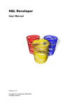
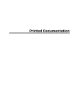
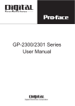
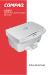
User’s Manual
SKALA
Scales designing software
version 3.06
SKALA ver. 3.06
Contents
1.
INSTALLATION ...............................................................................................................................................4
1.1
1.2
SYSTEM REQUIREMENTS FOR SKALA PROGRAM INSTALLATION ..................................................................4
INSTALLING PROGRAM SKALA ....................................................................................................................4
2.
SKALA CONCEPT ...........................................................................................................................................5
3.
SHORT DESCRIPTION OF THE SKALA PROGRAM ..............................................................................7
3.1
MAIN WINDOW ............................................................................................................................................7
3.1.1
Menus ..................................................................................................................................................7
3.1.2
Icons.....................................................................................................................................................8
3.1.3
Positions...............................................................................................................................................8
3.2
LOAD DIAL WINDOW..................................................................................................................................9
3.3
SAVE DIAL WINDOW ................................................................................................................................10
3.4 AUTOMATIC NUMBERING WINDOW ......................................................................................................11
3.5
HALF-AUTOMATIC NUMBERING WINDOW ........................................................................................12
3.6
MANUAL NUMBERING WINDOW...........................................................................................................13
3.7
NEW SYMBOL WINDOW...........................................................................................................................14
3.8
CHANGE TEXT WINDOW .........................................................................................................................15
3.9
LINE WINDOW ............................................................................................................................................16
3.10 CHANGE LINE WINDOW...........................................................................................................................17
3.11 ARC WINDOW .............................................................................................................................................18
12.
CHANGE ARC WINDOW ...........................................................................................................................19
3.12 SHOW DOT POSITION WINDOW .............................................................................................................20
3.13 GUIDE LINE WINDOW ...............................................................................................................................20
3.14 LOGO WINDOW ..........................................................................................................................................20
3.15 SMALL CROSS WINDOW ..........................................................................................................................21
3.16 PRINT WINDOW .........................................................................................................................................22
3.17 DIMENSIONS WINDOW ............................................................................................................................23
3.18 COMMENT WINDOW .................................................................................................................................24
3.19 TABLE WINDOW ........................................................................................................................................24
4.
EXAMPLES OF SCALE CREATING BY SKALA .....................................................................................25
4.1
LOADING DIAL ............................................................................................................................................25
4.2
CREATING SCALE WITH AUTOMATIC NUMBERING METHOD ...............................................................25
4.3
CREATING SCALE WITH HALFAUTOMATIC NUMBERING METHOD .....................................................28
4.4
ADDING MARKS ON THE SCALE WITH MANUAL NUMBERING METHOD .................................................31
4.5
SAVING DIAL WITH NEW NAME ....................................................................................................................32
4.6
DELETING DIAL FROM HARD DISK ...............................................................................................................32
4.7
PRINTING DIAL ............................................................................................................................................32
4.8
SYMBOLS ....................................................................................................................................................32
4.8.1
Inserting new symbol..........................................................................................................................32
4.8.2
Inserting text.......................................................................................................................................33
4.8.3
Moving symbols..................................................................................................................................33
4.8.4
Deleting symbols ................................................................................................................................33
4.8.5
Changing symbols properties.............................................................................................................33
4.9
LINES ..........................................................................................................................................................34
4.9.1
Drawing lines .....................................................................................................................................34
4.9.2
Moving lines .......................................................................................................................................34
4.9.3
Deleting lines......................................................................................................................................35
4.9.4
Changing lines properties ..................................................................................................................35
4.10 ARCS ...........................................................................................................................................................35
4.10.1 Drawing arcs......................................................................................................................................35
4.10.2 Moving arcs........................................................................................................................................37
4.10.3 Deleting arcs ......................................................................................................................................37
4.10.4 Changing arcs properties...................................................................................................................37
2
SKALA ver. 3.06
4.11 LOGOTYPES .................................................................................................................................................37
4.11.1 Inserting logotype...............................................................................................................................37
4.11.2 Moving logotype.................................................................................................................................37
4.11.3 Deleting logotype ...............................................................................................................................38
4.12 ADDING NEW SCALE ON THE DIAL ...............................................................................................................38
4.13 HOW TO USE SCALE DATA FROM THE TABLE WINDOW.................................................................................39
4.14 PLACING DOT MARK ....................................................................................................................................40
4.15 COPYING AND PASTING OBJECTS .................................................................................................................40
5.
APPENDIX A ...................................................................................................................................................41
6.
APPENDIX B ...................................................................................................................................................42
3
SKALA ver. 3.06
1. Installation
1.1 System requirements for SKALA program installation
System requirements are:
• an IBM compatible computer with an Intel Pentium 100 or better
• at least 30MB of free space on your hard disk
• a 1024 x 768 resolution and 256-color video card
• a 17’’ monitor
• Windows 95 or greather versions
1.2 Installing program SKALA
To install SKALA,
• start Windows
• insert the Skala CD-ROM into the CD-ROM drive
• find and run file “X:install\setup.exe” ( where “X” is the letter of the CD-ROM drive)
• follow the instructions
• after installation restart computer
• open and close windows fonts folder ( ...windows\fonts), in this way windows
operating system recognize new installed fonts
• recommended screen resolution is 1024x768 , 256-colors and Large Fonts
• install printer driver for HP23200L, when installation program ask for a driver select
PS ( postscript) not PCL6 because only PS driver is able to print mirror image
• after installation printer driver, set mirror function :
(Start – Settings – Printers and faxes – HP laser 2300L PS – Properties- Printing
Preferences – Advanced – Document Options – PostScript Options – Mirrored
Output - Yes).
• create the shortcut of SKALA on the desktop
1.3 Installing data base
To install data base,
• insert the Skala CD-ROM into the CD-ROM drive
• copy directories “X:Skala\data” ( where “X” is the letter of the CD-ROM drive) to
c:\Skala\data
• Attention: The copied files from CD have Read only attribute. It means that you can
not modify. To disable Read only attribute select desired files and with right click on
mouse select properties and remark Read only option.
4
SKALA ver. 3.06
2. SKALA concept
• Dials in a Main window are designed and viewed. On the top and on the left margin
of the Main window icons for quick access are placed.
• Cursor position in the bottom margin of the Main window is displayed. The text
boxes Abs. X and Y (30) contains cursor position from the bottom-right corner of the
dial. The text boxes Rel. X and Y (32) display cursor position from the relative origin
defined in the text box Rel. Origin (31). To change the relative origin, set the new
origin in the text box Rel. Origin (31) or move cursor on the dial and click left mouse
button and key O on keybord.
• To enlarged the drawing, click ZOOM icon (26) and select desired detail on the
drawing. Scroll bars (33) move drawing view in all directions.
• SKALA uses five groups of objects: lines, arcs, symbols, picture and dial outline
dimensions.
• Lines group contains lines, small crosses and marks on scales. Lines properties are:
length, width, colour, drawing angle. To select line on the drawing click into the area
shown in Picture 1.
• Symbols group contains text, units, logotypes .… Symbols use Windows TrueType
fonts. Symbols properties are: Font name, Font size, text, colour and angle. To select
symbol click it into the area shown in Picture 1. Contents of fonts are in Appendix B.
Program uses fonts defined in file “c:\skala\system\fonts.txt”.
• Arcs group contains circles, dot and arcs. Arcs properties are: radius, start point,
angle, length and colour. To select arc click it into the area shown in Picture 1.
Picture 1
• Picture is in Windows bitmap (.bmp) black-white format. Picture group for logotypes
is used. Maximal image dimension is 1200x1200 pixels.
• Dial outline dimensions contains: dial dimensions, position of units, position of
symbols, position of logotypes and scales outline. Dial can contains up to six scales.
Every scale outline on dial have its own colour and number.
5
SKALA ver. 3.06
Picture 2
• SKALA uses the following data files (8.3 file name format):
• .skl files for dial data
• .kar files for scales characteristic data. Data in file are in two columns separated
by commas. First column contains values in percent started with 0. Second
column contains angle value. In Appendix A is an example of scale
characteristic file.
• .ost files contains numbering rules. Each row in file describes one range. Row
contains: range, number of marks, medium marks skipping, main marks skipping
and number skipping. In Appendix A is an numbering file example.
6
SKALA ver. 3.06
3. Short description of the SKALA program
3.1 MAIN window
3.1.1 Menus
1. File menu:
Load - opens the Load window for
loading dials.
Save - saves current drawing.
Save As - opens New dial window
for new dial saving.
Delete - opens New dial window for
deleting dials.
Exit - closes program.
2. Data
3. Output menu:
Print - opens Print window for dial
printing.
Characteristic - shows main scale
data.
Nr. Dial - counts created dials.
4. Design - menu
Dimensions - opens the Dimensions
window for creating dial dimensions.
Division
Automatic - creates standard
scales.
Half-automatic - creates nonstandard scales.
Manual - draws marks.
Symbol - draws symbols and texts.
Logo - draws images.
Arc - draws arcs and circles.
Point - draws small cross.
Comment
5. Erase menu
Scale - erases selected scale.
All - erases all objects.
Symbols - erases all characters.
Dots erases all dots.
Picture erase selected picture.
7
SKALA ver. 3.06
3.1.2 Icons
6.
7.
8.
9.
10.
11.
12.
13.
14.
15.
16.
17.
18.
19.
20.
21.
22.
23.
24.
25.
26.
27.
28.
29.
Open icon shows load dial window.
Save icon saves drawing.
Undo icon cancels some last actions (deleting, changing, moving).
Print icon prints current dial.
Table icon shows table window.
Line icon enables drawing lines.
Arc icon enables drawing arcs.
Logo icon place image.
Symbol icon writes symbols and text.
Erase scale icon erases scale with number 1.
Automatic icon automates drawing of divisions.
Half automatic icon draws non-standard scales.
Manual icon draws divisions one by one.
Dot icon places dot under mark.
Dimension icon enables changing dial dimension.
Select icon enables selecting objects.
Text icon enables text and symbols selection.
Arc icon enables arc selection.
Line select icon enables line selection.
Move text icon quick moves selected text.
Zoom icon enlarges selected drawing area.
Guide line icon draws horizontal and vertical guide lines.
Copy icon copies selected objects.
Paste icon pastes objects.
3.1.3 Positions
30.
31.
32.
33.
Cursor’s x & y Absolute co-ordinate in mm.
Relative origin in mm.
Cursor’s x & y Relative co-ordinate in mm.
Horizontal scroll bar moves drawing up and down. Vertical scroll bar moves
drawing left and right.
34. Drawing area.
8
SKALA ver. 3.06
3.2 LOAD DIAL window
1. Code text box is used to write 12-characters code
number.
2. Search button searches dials by code.
3. By clicking on the file name in File list box new dial is
loaded.
4. Directory list box.
5. Drive list box.
9
SKALA ver. 3.06
3.3 SAVE DIAL window
1.
2.
3.
4.
5.
6.
7.
8.
9.
Save new dial command saves current dial with new name and new code.
File name box contains name of dial.
New code box contains 12-characters code of dial.
File list box contains list of file names.
Drive list box.
Directory list box.
Delete dial by name command deletes dial with name defined in the File name box (2).
Delete dial by code command deletes dial with code defined in the New code box (3).
Create new directory command creates new directory with name defined in the File
name box (2) and set it on the place defined in the Directory list box (6).
10.Cancel command leaves SAVE DIAL window .
10
SKALA ver. 3.06
3.4 AUTOMATIC NUMBERING window
1.
2.
3.
4.
5.
6.
7.
8.
9.
10.
11.
12.
13.
14.
15.
16.
Scale number box defines scale.
Value at 0% must be always 0.
Value at 100% is the number at 100% of scale.
Extend check box enables numbering extended scale (15/30, 10/12, 100/600).
Extend intermediate value is the number between 100% and extend end value.
Extend final value is the number at the end of extended scale.
Checked Scale characteristic from Table reads characteristic data from table
created in Table window.
By clicking on the Scale characteristic file box you change characteristic file path.
By clicking on the Numbering file box you change numbering file name.
Checked Rectangle draws rectangle at the beginning of the scale. Rectangle
dimension is defined in width and height box.
Checked Without marks omits the marks. Text box defines area without marks at
the beginning of the scale.
Checked Arc draws arc from start to the end of the scale.
Checked Rotate number draws numbers right-angled to the marks.
Font name list box defines font style of the number on the scale.
Draw command draws scale.
Cancel command leaves Automatic numbering window without draw new scale.
11
SKALA ver. 3.06
3.5 HALF-AUTOMATIC NUMBERING window
1.
2.
3.
4.
5.
6.
7.
8.
9.
10.
11.
12.
13.
14.
15.
16.
17.
18.
19.
Scale number box defines scale.
Value at 0% must be smaller then end value.
Origin value must be one of the main mark on the scale. The value must be
between Value at 0% and Value at 100%.
Value at 100% must be greater then Value at 0%.
Number in text box defines number of marks before Medium line.
Number in text box defines number of marks before Main line.
Number in text box defines number of marks before the number is drawn.
Division value defines value of marks.
Checked Rectangle draws rectangle at the beginning of the scale. Rectangle
dimension is defined in width and height box.
Checked Without marks omits the marks. Text box defines area without marks at
the beginning of the scale.
Checked Arc draws arc from start to the end of the scale.
Checked Minus box writes minus at negative numbers.
In Scale characteristic file the characteristic file path can be changed.
Checked Scale characteristic from Table reads scale characteristic data from
table created in Table window.
Font name list box defines font style of the number on the scale.
Checked Electric zero compresses scale for a degree written in text box.
Checked Rotate number draws numbers right-angled to the marks.
Draw command draws scale.
Cancel command leaves Half-automatic numbering window without drawing the
new scale
12
SKALA ver. 3.06
3.6 MANUAL NUMBERING window
1.
2.
3.
4.
5.
6.
7.
8.
9.
10.
11.
12.
13.
14.
Scale number box defines scale.
Checked Scale characteristic from Table reads
characteristic data from table created in Table
window.
In the Scale characteristic file the characteristic file
path can be changed.
Selected option defines type of Mark.
Checked Number draws number written in text box.
Selected Percent option calculates division as
percent.
Add adds value from text box to Percent text box.
Selected Angle option calculates division as angle.
Add adds value from text box to Angle text box.
Checked Rotate number draws numbers rightangled to the marks.
Colour list box defines colour of mark and number.
Font name list box defines font style of the number
on the scale.
Draw command draws mark and number.
Cancel command leaves Manual numbering
window.
13
SKALA ver. 3.06
3.7 NEW SYMBOL window
1.
2.
3.
4.
5.
6.
7.
8.
9.
Font name list box defines symbols font name.
Font size text box defines symbol size in millimetres.
Selected Sym. option takes symbol from the table (4).
Table shows 26 symbols with ASCII code. Selected
symbol in the table is red.
With Up and Down arrows shows other symbols.
OK command draws selected symbol or string of the
symbols on the dial.
Selected String option uses string symbols from text
box (8).
String text box contains string of the symbols.
Cancel command leaves New symbol window.
14
SKALA ver. 3.06
3.8 CHANGE TEXT window
1.
2.
3.
4.
5.
6.
7.
8.
Checked Font name changes font style of selected
symbols with selected font below.
Checked Text changes symbols with symbol or text
below.
Checked Colour changes colour of selected
symbols with below defined colour.
Checked Font size changes size of selected
symbols with below defined size.
Rotate text box shows angle of rotated symbol
Change command changes selected symbols.
Delete command deletes selected symbols.
Cancel command does not change selected
symbols.
15
SKALA ver. 3.06
3.9 LINE window
1.
2.
3.
4.
5.
6.
7.
8.
9.
10.
11.
12.
13.
14.
15.
Picture explains line’s required data.
When key »P« is pressed in drawing area, x and
y position of cursor in (3) and (5) text boxes are
copied.
Pos. X defines position X of the line’s start in mm.
Add adds up value from the text box to the Pos.
X text box (3).
Pos. Y text box defines position Y of line’s start in
mm.
Add text box adds up value from text box (6) to
the Pos. Y text box (5).
Selected Absolute option draws line from the
absolute origin.
Selected Relative option draws line from the
relative origin.
When key »K« is pressed in drawing area line
length and angle are calculated.
Length defines line length in mm.
Angle defines line angle from the X axis in
degrees.
Width defines line width in mm.
Colour defines line colour.
Draw button draws line.
Cancel button leaves Line window.
16
SKALA ver. 3.06
3.10 CHANGE LINE window
1.
2.
3.
Value shows mark value.
Angle shows mark angle in degrees.
Checked Colour changes colour of selected lines
with colour defined.
4. Checked Length changes selected lines length.
5. Checked Width changes selected lines width.
6. Rotate shows angle of selected line.
7. Spin command rotates selected line up and down
by 1 or 5 degrees.
8. Checked Marks uses selected line as marks from
scale.
9. Change command makes changes of selected
lines.
10. Delete command deletes selected lines.
11. Cancel command does not change selected lines.
17
SKALA ver. 3.06
3.11 ARC window
1. Copy from scale command copies scale
dimension in to the Centre X (2),Y (3), and to the
Radius (4). Scale is defined in text box (1).
2. Centre X arc centre X in mm.
3. Centre Y arc centre Y in mm.
4. Radius arc radius in mm.
5. Picture explains arc’s required data.
The latter in quotation defines keys.
By pressing key C in Main window program
transfers the cursor co-ordinates into Centre
X,Y(3,4).
By pressing key R in Main window program
calculates the Radius from Centre X,Y(3,4) to
cursor and writes in Radius (4).
By pressing key S in Main window program
calculates the Start angle and writes in Start (6).
By pressing key L in Main window program
calculates the Length of arc in degrees and writes
in Length (7).
6. Start defines start of the angle in degrees.
7. Length defines arc angle length in degrees.
8. Width defines arc line width in mm.
9. Colour defines arc colour.
10. Draw button draws arc.
11. Cancel button leaves ARC window.
18
SKALA ver. 3.06
12. CHANGE ARC window
1.
2.
3.
4.
5.
6.
7.
8.
Checked Radius changes arc radius.
Checked Start changes start the arc angle.
Checked Length changes arc length angle.
Checked Width changes arc width.
Checked Colour changes arc colour.
Change command changes selected arc.
Delete command delete selected arc.
Cancel command does not change selected arc.
19
SKALA ver. 3.06
3.12 SHOW DOT POSITION window
1.
2.
3.
4.
5.
Dot diameter in mm.
Distance between number and mark
in mm.
Selected option shows position of
Dot.
Draw command draws dot.
Cancel does not draw dot.
3.13 GUIDE LINE window
1.
2.
3.
ver.I command draws vertical guide lines.
hor.- command draws vertical guide lines.
Delete command deletes all guide lines.
3.14 LOGO window
1.
2.
3.
4.
5.
6.
By clicking on the Logo name file box new logo image can be selected.
Height defines image height in mm.
Ratio shows ratio between width and height of picture.
Shows selected image.
Draw command draws selected image.
Cancel command does not draw logo image.
20
SKALA ver. 3.06
3.15 SMALL CROSS window
1.
2.
3.
4.
5.
6.
7.
8.
9.
Height defines cross height.
Thickness defines cross thickness.
When key »P« is pressed in drawing area,
cursor x and y co-ordinates in to (4) and (5) are
copied.
X defines X position of cross.
Y defines Y position of cross.
Selected Absolute option draws cross from the
absolute origin. Relative option draws cross
from the relative origin.
Colour defines cross colour.
Draw button draws cross.
Cancel button leaves Cross window.
21
SKALA ver. 3.06
3.16 PRINT window
1.
2.
3.
4.
5.
6.
7.
8.
9.
10.
11.
12.
13.
14.
15.
16.
17.
18.
19.
20.
21.
22.
Portrait command rotates paper in to portrait position.
Landscape command rotates paper in to landscape position.
Set up printer command opens printer driver window.
Set printer driver changes printer driver.
Printer driver shows selected printer driver.
Printer correction defines dial size by X and Y axis correction.
Checked Dimension prints dial dimension.
Checked Comment prints comment below the dial.
Checked Colour separation check box prints only coloured objects with
selected colour (10).
Selected colour.
Width shows paper width in mm.
Height shows paper width in mm.
X shows position of left dial edge on the paper.
Y shows position of left dial edge on the paper.
Zoom defines magnification factor of the printed dial.
Copies defines number of copies.
Centre button moves dial to the centre of the paper.
Dial frame enables moving dial on the paper.
Print prints dial.
Save as BMP saves dial as picture on disk.
Corel export command exports dial in Postscript format on disk ( this
command is disabled ).
Cancel button leaves Print window without printing.
22
SKALA ver. 3.06
3.17 DIMENSIONS window
1.
2.
3.
4.
5.
6.
7.
8.
9.
10.
11.
12.
13.
14.
15.
Dial width dimension in mm.
Dial height dimension in mm.
Scale centre in mm.
Distance to the stretched scale centre in
mm (multimeter scales).
Scale radius in mm.
Start of Scale angle in degrees.
Scale length in degrees.
Short marks length and width dimension
in mm.
Long marks length and width dimension in
mm.
Medium marks length and width
dimension in mm.
Thick main marks length and width
dimension in mm.
Thin main marks length and width
dimension in mm.
Distance between number and line in
mm.
Dot diameter in mm.
The negative value -1 draws number
between marks and scale centre. The
positive value 1 draw number out from the
scale centre.
16. Unit position defines left-bottom corner of
Unit.
17. Symbols position defines left-bottom
corner of Symbols.
18. Logo position defines right -bottom corner
of logo.
19. Large number font size in mm.
20. Small number font size in mm.
21. Name of the Scale characteristic file.
22. Name of the Scale numbering file.
23. Number of scales on dial.
24. Copy from scale copies data from scale,
defined in the text box, in to the current
scale.
25. Next replaces current scale values with
next scale values.
26. Previous replaces current scale values
with previous scale values.
27. Save saves data in current dial file.
28. Cancel leaves dimension window without
save data.
29. Tittle of DIMENSIONS window shows
CURRENT SCALE number.
23
SKALA ver. 3.06
3.18 COMMENT window
1.
2.
3.
4.
5.
6.
7.
Date text box contains current date.
Dial text box with dial comment.
Code text box contains dial code.
Constructor list box identifies dial constructor (c:\skala\system\creators.txt).
File box shows dial file name.
Change command changes dial comment.
Cancel command leaves Comment window.
3.19 TABLE window
7
1.
Fifteen Value text boxes are used to write scale
values. Scale values have to increase.
2. Fifteen Angle text boxes are used to write scale
angles. Scale angle have to increase.
3. Selected Linear option uses linear interpolation
method for scale characteristic calculation.
4. Selected Cubic option uses cubic interpolation
method for scale data calculation.
5. Last point defines number of scale points.
6. Percent defines reference start and end percent
of scale.
7. Value defines reference start and end value.
8. Angle defines reference start and end angle.
9. Save as command saves table data under new
file name.
10. Table command saves table data.
11. Cancel command leaves TABLE window.
24
SKALA ver. 3.06
4. Examples of scale creating by SKALA
4.1 Loading dial
1. Click the icon (6, page 7) in the Main window to open LOAD DIAL window.
2. Type the dial Code and press Search by code to find dial or find the dial file name in
the File name box.
4.2 Creating scale with AUTOMATIC NUMBERING method
Example A shows how the normal scale with range 0...15 and linear characteristic is
designed.
1. Load dial C:\SKALA\EXAMP\1.SKL.
2. Erase the current scale by clicking icon (15, page 7) in the Main window.
3. To open the AUTOMATIC NUMBERING window, click on the icon (16, page 7) in the
Main window.
4. Write the data to the AUTOMATIC NUMBERING window:
5.
6.
Click DRAW button (15, page 11).
The new scale will be displayed in the main window as Picture 3.
Picture 3
25
SKALA ver. 3.06
Example B shows how scale with extended range 0...1.6/3.2 and F6 characteristic is
designed.
1. Load dial C:\SKALA\EXAMP\2.SKL.
2. Erase the current scale by clicking icon (15, page 7) in the main window.
3. To open the AUTOMATIC NUMBERING window, click icon (16, page 7) in the Main
window.
4. Write the data to the AUTOMATIC NUMBERING window:
5. Click DRAW (15, page 11).
6. The new scale will be displayed in the main window as Picture 4.
Picture 4
26
SKALA ver. 3.06
Example C shows how scale for bimetal instrument with range 0...720 and bimetal 5A
characteristic is designed.
1. Load dial C:\SKALA\EXAMP\3.SKL.
2. Erase the current scale by clicking icon (15, page 7) in the Main window.
3. To open the AUTOMATIC NUMBERING window, click icon (16, page 7) in the Main
window.
4. Write the data to the AUTOMATIC NUMBERING window:
5. Click command DRAW (15, page 11).
6. The new scale will be displayed in the Main window as Picture 5.
Picture 5
27
SKALA ver. 3.06
4.3 Creating scale with HALFAUTOMATIC NUMBERING method
Example A shows how scale with range -10...15 and linear characteristic is designed.
1. Load dial C:\SKALA\EXAMP\4.SKL.
2. Erase the current scale by clicking icon (15, page 7) in the Main window.
3. Open the HALFAUTOMATIC NUMBERING window, by clicking icon (17, page 7) in
the Main window.
4. Write the data to the HALFAUTOMATIC NUMBERING window:
5. Click the command DRAW (18, page 12).
6. The new scale will be displayed in the Main window as Picture 6.
Picture 6
28
SKALA ver. 3.06
Example B shows how scale with range 54...66 electric zero at 5 degrees and linear
characteristic is designed.
1. Load dial C:\SKALA\EXAMP\5.SKL.
2. Erase the current scale by clicking icon (15, page 7) in the Main window.
3. Open the HALFAUTOMATIC NUMBERING window, by clicking icon (17, page 7) in
the Main window.
4. Write the data to the HALFAUTOMATIC NUMBERING window:
5. Click command DRAW (18, page 12).
6. The new scale will be displayed in the Main window as Picture 7.
Picture 7
29
SKALA ver. 3.06
Example C shows how scale with characteristics shown on the Picture (8) is designed.
1. Load dial C:\SKALA\EXAMP\4.SKL.
2. Erase the current scale by clicking icon (15, page 7) in the Main window.
3. Open the HALFAUTOMATIC NUMBERING window, by clicking icon (17, page 7) in
the Main window.
4. Write the data to the HALFAUTOMATIC NUMBERING window:
5. Click command DRAW (18, page 12).
6. The new scale will be displayed in the Main window.
Picture 8
30
SKALA ver. 3.06
4.4 Adding marks on the scale with MANUAL NUMBERING method
Example A shows numbered black mark on the scale with 67 degrees angle is placed.
1.
2.
3.
4.
5.
Load dial C:\SKALA\EXAMP\5.SKL.
Open the MANUAL NUMBERING window, by clicking
icon (18, page 7) in the Main window.
Write the data to the MANUAL NUMBERING window.
Click the command DRAW (13, page 13).
The new mark will be added on the scale as shown on
the Picture 9.
Picture 9
Example B shows placing green mark at 70
percent value of the scale.
1. Load dial C:\SKALA\EXAMP\5.SKL.
2. Open the MANUAL NUMBERING window, by clicking
icon (18, page 7) in the Main window.
3. Write the data to the MANUAL NUMBERING window:
4. Click command DRAW (13, page 13).
5. The new mark will be added on the scale as shown on
the Picture 10.
Picture 10
31
SKALA ver. 3.06
4.5 Saving dial with new name
1. Load dial C:\SKALA\EXAMP\3.SKL.
2. Select Save As from the File menu (1, page 7).
3. In the SAVE DIAL window, select directory C:\SKALA\TEST\ from the Directory list
box (6, page 10)
4. In the File name text box, type »TEST1«.
5. In the New code text box, type »TEST00000001«.
6. Click command SAVE NEW DIAL to save dial.
4.6 Deleting dial from hard disk
Example A shows deleting dial by using dial name.
1. Choose Save As from the File (1, page 7) menu.
2. In the SAVE DIAL window, select dial in the File list (4, page 10).
3. To delete dial, click DELETE DIAL BY NAME (7, page 10).
Example B shows deleting dial using dial code.
1. Choose Save As from the File (1) menu.
2. In the SAVE DIAL window type dial code in the New code text box (3, page 10).
3. To delete selected dial, click DELETE DIAL BY CODE (8, page 10).
4.7 Printing dial
Example A shows procedure for mirror dial printing in three copies.
1. Load dial C:\SKALA\EXAMP\3.SKL.
2. Open the PRINT window, by clicking icon (9, page 7) in the Main window.
3. In the PRINT window, printer which is able to print mirror image have to be selected.
4. Type number 3 in the Copies text box (16, page 22).
5. To print dial, click PRINT button (19, page 22).
Example B shows zoomed dial printing.
1. Load dial C:\SKALA\EXAMP\3.SKL.
2. Open the PRINT window, by clicking icon (9, page 7) in the Main window.
3. In the PRINT window select non-mirror type printer.
4. Type number 2 in the Zoom text box (15, page 22).
5. To print the dial, click PRINT (19, page 22).
4.8 Symbols
4.8.1 Inserting new symbol
1.
2.
3.
4.
5.
6.
7.
8.
Load dial C:\SKALA\EXAMP\5.SKL.
Open the NEW SYMBOL window, by clicking icon (14, page 7) in the Main window.
In the NEW SYMBOL window set “_D_SYMBOL” in the Font Name list box.
Set Font size (2, page 14) to 3.
Select option Sym. (3, page 14) and choose the symbol from the table (4, page 14).
Click OK button (6, page 14).
Move the cursor to the drawing area.
Click the mouse to put the symbol on the dial.
32
SKALA ver. 3.06
4.8.2 Inserting text
1. Load dial C:\SKALA\EXAMP\5.SKL.
2. Open the NEW SYMBOL window with icon (14, page 7) in the Main window.
3. In the NEW SYMBOL window set “_H_CON_B_” in the Font Name list box (1, page
14).
9. Set Font size (2, page 14) to 5.
4. Select option String (7, page 14) and type text “AMPER” in the text box (8, page 14).
5. Click OK Button (6, page 14).
6. Move the cursor in the drawing area.
7. Click the mouse to put text on the dial.
4.8.3 Moving symbols
1.
2.
3.
4.
Load dial C:\SKALA\EXAMP\3.SKL.
To select symbols click icons (21, page 7) and (22, page 7) in the Main window.
Find the symbol “A” on the dial.
Move cursor to the left-top corner of the symbol (see Picture 1) and click. Selected
symbol becomes dark green.
5. To move symbol, press the cursor key on the keyboard.
6. Combination of keys (cursor key + Shift or cursor key + Ctrl) moves selected symbol
faster.
7. To deselect symbol on the dial, click the right mouse key or click icon (21, page 7) on
the Main window or click CANCEL in the CHANGE TEXT window.
4.8.4 Deleting symbols
1.
2.
3.
4.
5.
6.
Load dial C:\SKALA\EXAMP\3.SKL.
To select symbols click icons (21, page 7) and (22, page 7) in the Main window.
Set the symbols ”A”, “F” and “600” on the dial.
Move cursor to the left-top corner of the first symbol and click.
Likewise select the other two symbols.
To delete symbols, click command DELETE (7, page 15) in the CHANGE TEXT
window.
7. Action can be undone by UNDO icon (8, page 7) in the Main window.
4.8.5 Changing symbols properties
1.
2.
3.
4.
5.
6.
Load dial C:\SKALA\EXAMP\3.SKL.
To select symbol, click icons (21, page 7) and (22, page 7) in the Main window.
Set symbol “A”.
Move cursor to the left-top corner of the symbol and click.
The CHANGE TEXT window will be opened on the right side.
To change a colour of the symbol, set RED colour in the COLOUR list box (3, page
15) and set check box.
7. Click CHANGE (6, page 15) button and symbol will be coloured to red.
8. Action can be undone by UNDO icon (8, page 7) in the Main window.
33
SKALA ver. 3.06
4.9 Lines
4.9.1 Drawing lines
Example A shows drawing line with manual method.
1. Load dial C:\SKALA\EXAMP\6.SKL.
2. Open the LINE window by icon (11, page 7) in the Main
window.
3. In the LINE window type the data.
4. Click DRAW button and the new line will be placed on the
dial.
Example B shows drawing line by transferring cursor’s co-ordinates
1. Load dial C:\SKALA\EXAMP\6.SKL.
2. Open the LINE window by icon (11, page 7) in the Main window.
3. Place the cursor to the left-top of the green rectangle of the drawing.
4. Click mouse to make main window active and then press key “P” on the keyboard.
The cursor’s co-ordinates will be transferred in to the Pos. X (3, page 16) and Pos. Y
(5, page 16).
5. Place the cursor to the right-bottom of the green rectangle of the drawing.
6. Click mouse to make Main window active and click “K” on the keyboard. The length
and angle of the line will be written in to the Length text box (10, page 16) and Angle
text box (11, page 16).
7. Click DRAW button (14, page 16) and the new line will be placed on the dial.
4.9.2 Moving lines
1.
2.
3.
4.
5.
6.
7.
8.
Load dial C:\SKALA\EXAMP\6.SKL.
To select line click icons (21, page 7) and (24, page 7) in the Main window.
Find the thick blue line on the dial.
Move cursor near to the end of the line (see Picture 1) and click. Selected line
becomes dark green.
To move line press the cursor key on the keyboard.
Combination of keys (cursor key + Shift or cursor key + Ctrl) moves selected line
faster.
To deselect line on the dial click the right mouse key or icon (21, page 7) in the Main
window or CANCEL button in the CHANGE LINE window.
Action can be undone by UNDO icon (8, page 7) in the Main window.
34
SKALA ver. 3.06
4.9.3 Deleting lines
1.
2.
3.
4.
Load dial C:\SKALA\EXAMP\6.SKL.
To select line click icons (21, page 7) and (24, page 7) in the Main window.
Find the thick blue line on the dial.
Move cursor near to the end of line (see Picture 1) and click. Selected line becomes
dark green.
5. To delete line click DELETE in the CHANGE LINE window.
6. Action can be undone by UNDO icon (8, page 7) in the Main window.
4.9.4 Changing lines properties
1.
2.
3.
4.
Load dial C:\SKALA\EXAMP\6.SKL.
To select line click icons (21, page 7) and (24, page 7) in the Main window.
Find the thick blue line on the dial.
Move cursor near to the end of the line (see Picture 1) and click. The CHANGE LINE
window will be opened on the right side.
5. To change colour of the line select RED colour in the COLOUR list box (3, page 17)
and set check box.
6. Click CHANGE button (9, page 17) and selected line will be coloured to red.
7. Action can be undone by UNDO icon (8, page 7) in the Main window.
4.10 Arcs
4.10.1 Drawing arcs
Example A shows drawing arc manually.
1. Load dial C:\SKALA\EXAMP\6.SKL.
2. Open the ARC window by icon (12, page 7) in the Main
window.
3. In the ARC window type data.
4. Click DRAW (11, page 18) and the new arc will be placed
on the dial.
35
SKALA ver. 3.06
Example B shows drawing arc by COPY FROM SCALE procedure.
1. Load dial C:\SKALA\EXAMP\6.SKL.
2. Open the ARC window by icon (12, page 7) in the Main
window.
3. Set number 1 in text box (1, page 18) and click COPY
FROM SCALE button.
4. The Centre X, Y and Radius data from the scale are
transferred.
5. Type the data in the ARC window.
6. Click DRAW (11, page 18) and the new arc will be added
on the dial.
Example C shows drawing arc by transferring cursor’s co-ordinates
1. Load dial C:\SKALA\EXAMP\6.SKL.
2. Open the ARC window by icon (12, page 7) in the Main
window.
3. Place the cursor to the centre of the arc click.
4. The cursor’s co-ordinates will be transferred in to the
Centre X and Centre Y by pressing "P" key.
5. Type the data on the ARC window.
6. Click DRAW (11, page 18) and the new arc will be added
to the dial.
36
SKALA ver. 3.06
4.10.2 Moving arcs
1.
2.
3.
4.
5.
6.
7.
8.
Load dial C:\SKALA\EXAMP\6.SKL.
To select arc click icons (23, page 7) and (21, page 7) in the Main window.
Find the thick green arc on the dial.
Move cursor into the arc’s line (see Picture 1) and click. Selected arc becomes dark
green.
To move arc, press the cursor key on the keyboard.
Combination of keys (cursor key + Shift or cursor key + Ctrl) moves selected arc
faster.
To deselect arc on the dial, click the right mouse key or click icon (21, page 7) in the
Main window or CANCEL in the CHANGE ARC window.
Action can be undone by UNDO icon (8, page 7) in the Main window.
4.10.3 Deleting arcs
1.
2.
3.
4.
Load dial C:\SKALA\EXAMP\6.SKL.
To select arc click icon (23, page 7) and (21, page 7) in the Main window.
Find the thick blue arc in the dial.
Move cursor into the arc’s line (see Picture 1) and click. Selected arc becomes dark
green.
5. To delete arc click DELETE in the CHANGE ARC window.
6. Action can be undone by UNDO icon (8, page 7) in the Main window.
4.10.4 Changing arcs properties
1.
2.
3.
4.
5.
6.
Load dial C:\SKALA\EXAMP\6.SKL.
To select arc click icon (23, page 7) and (21, page 7) in the Main window.
Find the thick blue arc in the dial.
Move cursor into the arc’s line (see Picture 1) and click.
The CHANGE ARC window will be opened on the right side.
To change the radius of the arc type new value in the Radius text box (1, page 19)
and set check box.
7. Click CHANGE (6, page 19) and arc will change radius.
8. Action can be undone by UNDO icon (8, page 7) in the Main window.
4.11 Logotypes
4.11.1 Inserting logotype
1. Load dial C:\SKALA\EXAMP\6.SKL.
2. Click LOGO icon (13, page 7) in the Main window,.
3. In the File dialogue box select logo file “instnew.log” and click OK. The LOGO
window will be opened.
4. Type number 5 in the Height text box (2, page 20) and click OK.
5. The logotype image will be added on the dial.
6. To move logo image, click inside the image and drag it.
4.11.2 Moving logotype
1. Load dial C:\SKALA\EXAMP\7.SKL.
2. To move a logotype image, click inside the image and drag it.
37
SKALA ver. 3.06
4.11.3 Deleting logotype
1. Load dial C:\SKALA\EXAMP\7.SKL.
2. To delete a logotype image choose PICTURE in the ERASE (5, page 7) menu.
With mouse select desire logotype.
4.12 Adding new scale on the dial
The Picture 2 shows dimensions that could be changed in DIMENSIONS window.
Example A shows adding new scale on the dial.
1. Load dial C:\SKALA\EXAMP\8.SKL.
2. Open the DIMENSION window by icon (20, page 7) in the Main window.
3. Type number 2 in the Number of scales text box (23, page 23).
4. Click Next (25, page 23) button. The DIMENSIONS window has no values for scale
number 2.
5. Click Copy from scale = 1 (24, page 23) to fill empty text boxes with data from scale 1.
6. Set the data.
7. Save new scale by SAVE (27, page 23) button.
38
SKALA ver. 3.06
4.13 How to use scale data from the Table window
1.
2.
3.
4.
Load dial C:\SKALA\EXAMP\4.SKL.
In the Main window click TABLE icon (10, page 7).
Type the data in it.
Click TABLE (10, page 24) button and the data will be
saved.
5. To draw scale with new data, delete current scale by icon (15, page 7) in the Main
window first.
7. Click icon (16, page 7) to open AUTOMATIC NUMBERING window and write the
data in it.
8. To draw scale with data from the Table click DRAW button.
39
SKALA ver. 3.06
4.14 Placing dot mark
1.
2.
3.
4.
Load dial C:\SKALA\EXAMP\3.SKL.
In the Main window click DOT icon (19, page 7) and select blue mark on the scale.
In the SHOW DOT POSITION window set dot position (3, page 20).
To draw dot click DRAW (4, page 20) button.
4.15 Copying and pasting objects
All selected objects could be copied on the dial except logotype image.
1. Load dial C:\SKALA\EXAMP\6.SKL.
2. First select green lines (see Moving lines), then green symbols (see Moving
symbol) and green arcs (see Moving arc).
3. Click COPY icon (28, page 7) in the Main window and select the origin of the objects.
4. Click PASTE icon (29, page 7) and click to paste objects to the new position.
5. Pasted objects are dark green and can be moved by cursor keys.
6. To deselect pasted objects click right mouse button or click icon (21, page 7).
40
SKALA ver. 3.06
5. Appendix A
Scale points file “LIN-90.kar” example:
0,0
50,45
100,90
Scale points file “Tabela.kar” example:
0 ,-1
35.71429 , 90
50 , 125
71.42857 , 160
85.71429 , 200
100 , 239
41
SKALA ver. 3.06
6. Appendix B
42
SKALA ver. 3.06
43
SKALA ver. 3.06
44
SKALA ver. 3.06
45