1
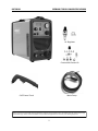
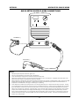
EVERLAST POWER PLASMA 50 IGBT DESIGN 50AMP PLASMA CUTTER CC PAC IGBT 1 ~ PHASE DC Operator’s Manual For PowerPlasma 50 Safety, Setup and General Use Guide Rev. 2 everlastwelders.com EVERLAST 1-877-755-9353 0 00312-13 Specifications and Accessories subject to change without notice. 329 Littlefield Ave. South San Francisco, CA 94080 USA Table of contents Section……………………………………………………………..Page Letter to the Customer ………………...…………………. 3 Everlast Contact Information……………………………. 4 Safety Precautions………………………………………….... 5 Introduction and Specifications…………………….….. 9 Unit Specifications……………………….…………………… 10 General Overview…………….…..………………………….. 11 General Use and Care………...…………………………….. 11 Quick Setup Guide, Plasma Connections…..……….. 12 Quick Setup Guide, Rear Connection for Plasma… 13 Front Panel Features and Controls…………………….. 14 Rear Panel Features and Controls……………………... 16 Plasma Function and Operation………………………....17 Plasma Torch S-45……………………………….…………….. 22 Troubleshooting………………………………………………....23 CNC Connector Pin-Out Appendix……………………….24 NOTE: Product Specifications and features are subject to change without notice. While every attempt has been made to provide the most accurate and current information possible at the time of publication, this manual is intended to be a general guide and not intended to be exhaustive in its content regarding safety, welding, or the operation/maintenance of this unit. Everlast Power Equipment INC. does not guarantee the accuracy, completeness, authority or authenticity of the information contained within this manual. The owner of this product assumes all liability for its use and maintenance. Everlast Power Equipment INC. does not warrant this product or this document for fitness for any particular purpose, for performance/accuracy or for suitability of application. Furthermore, Everlast Power Equipment INC. does not accept liability for injury or damages, consequential or incidental, resulting from the use of this product or resulting from the content found in this document or accept claims by a third party of such liability. 2 Dear Customer, THANKS! You had a choice, and you bought an Everlast. We appreciate you as a customer and hope that you will enjoy years of use from your welder. Please go directly to the Everlast website to register your unit and receive your warranty information. Your unit registration is important should any information such as product updates or recalls be issued. It is also important so that we may track your satisfaction with Everlast products and services. If you are unable to register by website, contact Everlast directly through the sales department through the main customer service number in your country. Your unit will be registered and warranty will be issued and in full effect. Keep all information regarding your purchase. In the event of a problem you must contact technical support before your welder can be a candidate for warranty service and returned. Please review the current online warranty statement and information found on the website of the Everlast division located in or nearest to your country. Print it for your records and become familiar of its terms and conditions. Everlast offers full technical support, in several different forms. We have online support available through email, and a welding support forum designed for customers and noncustomer interaction. Technical advisors are active on the forum daily. We also divide our support into two divisions: technical and welding performance. Should you have an issue or question concerning your unit, please contact performance/technical support available through the main company headquarters available in your country. For best service call the appropriate support line and follow up with an email, particularly during off hours, or in the event you cannot reach a live person. In the event you do not reach a live person, particularly during heavy call volume times, holidays, and off hours, leave a message and your call will normally be returned within 24 hours. Also,for quick answers to your basic questions, join the company owned forum available through the website. You’ll find knowledgeable, helpful people and staff available to answer your questions, and perhaps find a topic that already addresses your question at http://www.everlastgenerators.com/forums/. Should you need to call or write, always know your model name, purchase date and welder manufacturing inspection date. This will assure the quick and accurate customer service. REMEMBER: Be as specific and informed as possible. Technical and performance advisors rely upon you to carefully describe the conditions and circumstances of your problem or question. Take notes of any issues as best you can. You may be asked many questions by the advisors to clarify problems or issues that may seem very basic. However, diagnosis procedures MUST be followed to begin the warranty process. Advisors can’t assume anything, even with experienced users, and must cover all aspects to properly diagnose the problem. Depending upon your issue, it is advisable to have basic tools handy such as screwdrivers, wrenches, pliers, and even an inexpensive test meter with volt/ohm functions before you call. Let us know how we may be of service to you should you have any questions. Sincerely, Everlast Customer Service 3 Serial number: __________________________ Model number: ____________________________ Date of Purchase___________________________ EVERLAST Contact Information Everlast US: Everlast consumer satisfaction email: [email protected] Everlast Website: everlastwelders.com Everlast Technical Support: [email protected] Everlast Support Forum: http://www.everlastgenerators.com/forums/index.php Main toll free number: 1-877-755 WELD (9353) 9am—5pm PST M-F 11am-4pm PST Sat. FAX: 1-650-588-8817 Everlast Canada: Everlast consumer satisfaction email: [email protected] Everlast Website: everlastwelders.ca Everlast Technical Support: [email protected] Telephone: 905-637-1637 9am-4:30pm EST M-F 10am-1pm EST Sat. FAX: 1-905-639-2817 Everlast Austrailia: Sydney: 5A Karloo Parade Newport NSW 2106 (02) 9999 2949 Port Macquarie: 2B Pandorea Place Port Macquarie (02) 8209 3389 After hours support: 0413 447 492 Everlast Technical Support: [email protected] 4 Safety Precautions Everlast is dedicated to providing you with the best possible equipment and service to meet the demanding jobs that you have. We want to go beyond delivering a satisfactory product to you. That is the reason we offer technical support to assist you with your needs should an occasion occur. With proper use and care your product should deliver years of trouble free service. Safe operation and proper maintenance is your responsibility. We have compiled this operator’s manual, to instruct you in basic safety, operation and maintenance of your Everlast product to give you the best possible experience. Much of welding and cutting is based upon experience and common sense. As thorough as this welding manual may be, it is no substitute for either. Exercise extreme caution and care in all activities related to welding or cutting. Your safety, health and even life depends upon it. While accidents are never planned, preventing an accident requires careful planning. Please carefully read this manual before you operate your Everlast unit. This manual is not only for the use of the machine, but to assist in obtaining the best performance out of your unit. Do not operate the unit until you have read this manual and you are thoroughly familiar with the safe operation of the unit. If you feel you need more information please contact Everlast Support. The warranty does not cover improper use, maintenance or consumables. Do not attempt to alter or defeat any piece or part of your unit, particularly any safety device. Keep all shields and covers in place during unit operation should an unlikely failure of internal components result in the possible presence of sparks and explosions. If a failure occurs, discontinue further use until malfunctioning parts or accessories have been repaired or replaced by qualified personnel. Note on High Frequency electromagnetic disturbances: Certain welding and cutting processes generate High Frequency (HF) waves. These waves may disturb sensitive electronic equipment such as televisions, radios, computers, cell phones, and related equipment. High Frequency may also interfere with fluorescent lights. Consult with a licensed electrician if disturbance is noted. Sometimes, improper wire routing or poor shielding may be the cause. HF can interfere with pacemakers. See EMF warnings in following safety section for further information. Always consult your physician before entering an area known to have welding or cutting equipment if you have a pacemaker. 5 SAFETY PRECAUTIONS These safety precautions are for protection of safety and health. Failure to follow these guidelines may result in serious injury or death. Be careful to read and follow all cautions and warnings. Protect yourself and others. Welding and cutting processes produce high levels of ultraviolet (UV) radiation that can cause severe skin burn and damage. There are other potential hazards involved with welding such as severe burns and respiratory related illnesses. Therefore observe the following to minimize potential accidents and injury: Use appropriate safety glasses with wrap around shields while in the work area, even under welding helmets to protect your eyes from flying sparks and debris. When chipping slag or grinding, goggles and face shields may be required. When welding or cutting, always use an approved shielding device, with the correct shade of filter installed. Always use a welding helmet in good condition. Discard any broken or cracked filters or helmets. Using broken or cracked filters or helmets can cause severe eye injury and burn. Filter shades of no less than shade 5 for cutting and no less than shade 9 for welding are highly recommended. Shades greater than 9 may be required for high amperage welds. Keep filter lenses clean and clear for maximum visibility. It is also advisable to consult with your eye doctor should you wear contacts for corrective vision before you wear them while welding. Do not allow personnel to watch or observe the welding or cutting operation unless fully protected by a filter screen, protective curtains or equivalent protective equipment. If no protection is available, exclude them from the work area. Even brief exposure to the rays from the welding arc can damage unprotected eyes. Always wear hearing protection because welding and cutting can be extremely noisy. Ear protection is necessary to prevent hearing loss. Even prolonged low levels of noise has been known to create long term hearing damage. Hearing protection also further protects against hot sparks and debris from entering the ear canal and doing harm. Always wear personal protective clothing. Flame proof clothing is required at all times. Sparks and hot metal can lodge in pockets, hems and cuffs. Make sure loose clothing is tucked in neatly. Leather aprons and jackets are recommended. Suitable welding jackets and coats may be purchased made from fire proof material from welding supply stores. Discard any burned or frayed clothing. Keep clothing away from oil, grease and flammable liquids. Leather boots or steel toed leather boots with rubber bottoms are required for adequate foot protection. Canvas, polyester and other man made materials often found in shoes will either burn or melt. Rubber or other non conductive soles are necessary to help protect from electrical shock. Flame proof and insulated gauntlet gloves are required whether welding or cutting or handling metal. Simple work gloves for the garden or chore work are not sufficient. Gauntlet type welding gloves are available from your local welding supply companies. Never attempt to weld with out gloves. Welding with out gloves can result in serious burns and electrical shock. If your hand or body parts comes into contact with the arc of a plasma cutter or welder, instant and serious burns will occur. Proper hand protection is required at all times when working with welding or cutting machines! 6 SAFETY PRECAUTIONS WARNING! Persons with pacemakers should not weld, cut or be in the welding area until they consult with their physician. Some pacemakers are sensitive to EMF radiation and could severely malfunction while welding or while being in the vicinity of someone welding. Serious injury or death may occur! Welding and plasma cutting processes generate electro-magnetic fields and radiation. While the effects of EMF radiation are not known, it is suspected that there may be some harm from long term exposure to electromagnetic fields. Therefore, certain precautions should be taken to minimize exposure: Lay welding leads and lines neatly away from the body. Never coil cables around the body. Secure cables with tape if necessary to keep from the body. Keep all cables and leads on the same side the body. Never stand between cables or leads. Keep as far away from the power source (welder) as possible while welding. Never stand between the ground clamp and the torch. Keep the ground clamp grounded as close to the weld or cut as possible. Welding and cutting processes pose certain inhalation risks. Be sure to follow any guidelines from your chosen consumable and electrode suppliers regarding possible need for respiratory equipment while welding or cutting. Always weld with adequate ventilation. Never weld in closed rooms or confined spaces. Fumes and gases released while welding or cutting may be poisonous. Take precautions at all times. Any burning of the eyes, nose or throat are signs that you need to increase ventilation. Stop immediately and relocate work if necessary until adequate ventilation is obtained. Stop work completely and seek medical help if irritation and discomfort persists. WARNING! Do not weld on galvanized steel, stainless steel, beryllium, titanium, copper, cadmium, lead or zinc without proper respiratory equipment and or ventilation. WARNING! This product when used for welding or cutting produces fumes and gases which contains chemicals known to the State of California to cause birth defects and in some cases cancer. (California Safety and Health Code §25249.5 et seq.) WARNING! Do not weld or cut around Chlorinated solvents or degreasing areas. Release of Phosgene gas can be deadly. Consider all chemicals to have potential deadly results if welded on or near metal containing residual amounts of chemicals. Keep all cylinders upright and chained to a wall or appropriate holding pen. Certain regulations regarding high pressure cylinders can be obtained from OSHA or local regulatory agency. Consult also with your welding supply company in your area for further recommendations. The regulatory changes are frequent so keep informed. All cylinders have a potential explosion hazard. When not in use, keep capped and closed. Store chained so that overturn is not likely. Transporting cylinders incorrectly can lead to an explosion. Do not attempt to adapt regulators to fit cylinders. Do not use faulty regulators. Do not allow cylinders to come into contact with work piece or work. Do not weld or strike arcs on cylinders. Keep cylinders away from direct heat, flame and sparks. 7 SAFETY PRECAUTIONS continued WARNING! Electrical shock can kill. Make sure all electrical equipment is properly grounded. Do not use frayed, cut or otherwise damaged cables and leads. Do not stand, lean or rest on ground clamp. Do not stand in water or damp areas while welding or cutting. Keep work surface dry. Do not use welder or plasma cutter in the rain or in extremely humid conditions. Use dry rubber soled shoes and dry gloves when welding or cutting to insulate against electrical shock. Turn machine on or off only with gloved hand. Keep all parts of the body insulated from work, and work tables. Keep away from direct contact with skin against work. If tight or close quarters necessitates standing or resting on work piece, insulate with dry boards and rubber mats designed to insulate the body from direct contact. All work cables, leads, and hoses pose trip hazards. Be aware of their location and make sure all personnel in area are advised of their location. Taping or securing cables with appropriate restraints can help reduce trips and falls. WARNING! Fire and explosions are real risks while welding or cutting. Always keep fire extinguishers close by and additionally a water hose or bucket of sand. Periodically check work area for smoldering embers or smoke. It is a good idea to have someone help watch for possible fires while you are welding. Sparks and hot metal may travel a long distance. They may go into cracks in walls and floors and start a fire that would not be immediately visible. Here are some things you can do to reduce the possibility of fire or explosion: Keep all combustible materials including rags and spare clothing away from area. Keep all flammable fuels and liquids stored separately from work area. Visually inspect work area when job is completed for the slightest traces of smoke or embers. If welding or cutting outside, make sure you are in a cleared off area, free from dry tender and debris that might start a forest or grass fire. Do not weld on tanks, drums or barrels that are closed, pressurized or anything that held flammable liquid or material. Metal is hot after welding or cutting! Always use gloves and or tongs when handling hot pieces of metal. Remember to place hot metal on fire-proof surfaces after handling. Serious burns and injury can result if material is improperly handled. WARNING! Faulty or poorly maintained equipment can cause injury or death. Proper maintenance is your responsibility. Make sure all equipment is properly maintained and serviced by qualified personnel. Do not abuse or misuse equipment. Keep all covers in place. A faulty machine may shoot sparks or may have exploding parts. Touching uncovered parts inside machine can cause discharge of high amounts of electricity. Do not allow employees to operate poorly serviced equipment. Always check condition of equipment thoroughly before start up. Disconnect unit from power source before any service attempt is made and for long term storage or electrical storms. Further information can be obtained from The American Welding Society (AWS) that relates directly to safe welding and plasma cutting. Additionally, your local welding supply company may have additional pamphlets available concerning their products. Do not operate machinery until your are comfortable with proper operation and are able to assume inherent risks of cutting or welding. 8 Section 1 Introduction and Specifications Air Regulator Consumable Starter Kit S-45 Plasma Torch Work Clamp NOTE: Accessory and consumable style and quantities are subject to change without notice. Consumable starter kits provide only enough consumables to get started. Extra consumables can be purchased through Everlast or almost any local welding supply store. 9 Section 1 Introduction and Specifications Specification PowerPlasma 50 Inverter Type Analog, Fairchild IGBT Minimum/Maximum Rated Output 20 A/88 V - 50 A/100 V Start Type Blow-Back Type Torch Type S-45 12 ft. Duty Cycle @ Rated Amps/Volts ( 40° C) (Output V/A) 60% @ 50 A/ 100V 240 V 100% @ 40 A/ 96 V 240 V 60% @ 27 A/ 91 V 120 V 100% @ 20 A/ 88 V 120 V OCV (U0) 200 V Voltage Input (U1) Dual Voltage: 120 V/ 240 V; 50/60Hz 1 Phase Maximum Inrush Amps (I1MAX) 30 A @ 110V; 39 A @ 220 V; 37 @ 240V Maximum Rated Effective Amps (I1EFF) 25 A @ 110 V, 31 A @ 220V; 3 CNC Port Yes Air Post Flow Timer Adjustable Minimum Air Compressor Requirement 4.5 - 5 CFM @ 90 psi/ 30-60 gallon reserve Duty Cycle/ Over Current Protection Yes Minimum Operating Air Pressure (Safety Cut-Out Threshold) 35 psi Recommended Operating Air Pressure (Set with Air Flow set “Test”) 70-75 psi Maximum Supplied Air Pressure (From Compressor/Tank) 90 psi Recommended Maximum Average Cut Thickness (Hand Torch/Daily Use) 1/2” Recommended Daily Maximum Average Cut Thickness (CNC) 1/4” Rated Maximum Quality Cut @ 10-12 IPM (Steel) 3/4” Max Severance Cut @ 3 IPM (Steel ) 1” Minimum Water Ingress Protection Standard IP21S Efficiency >85% Cooling Method Full Time High Velocity Fan with Tunnel design Dimensions (approximate) 12.5” H X 7.5” W X 14” L Weight (Bare Unit) 35 lbs Generator Requirement 8,500 W Clean Power (less than 10% total harmonic distortion) Decrease maximum cut thickness values for aluminum and stainless by approximately 35%. When evaluating a plasma cutter for daily service, do not consider maximum severance cut values as criteria for routine use! These maximum specifications are intended for occasional situations that might require such a cut. Plan the unit’s daily use around the recommended average cut thickness for best results and speed. This is an industry standard recommendation and is not unique to Everlast PowerPlasma models. CNC cut thickness is further reduced as it is typically a 100% duty cycle operation which will require a lower maximum amp setting. Plasma performance specifications are based on reasonable environmental conditions with well maintained units, and cutting with new consumables using optimum air pressure. Actual performance results may vary in the field due to variable conditions, power supply, air pressure, air quality, consumable wear etc. 10 Section 1 Introduction and Specifications General overview: The PowerPlasma 50 utilizes the latest in inverter design technology. It’s a portable dual voltage plasma cutter with an output of 50 amps on 240V 1 phase power. It can also be used with 120 V (dual voltage models only) with limited output up to 27 amps. This design allows the unit to be used in many different circumstances and applications. The PowerPlasma 50 is also equipped with a CNC port (see appendix) for light or moderate CNC work. A separate CNC torch may be bought for this type of operation. The arc start incorporates a blow back design with an automatic pilot arc. The blow back design of the torch is depicted in detail located in the torch section of this manual. This unit features low air pressure protection along with duty cycle and overcurrent protection which will shut down output of the plasma cutter until the condition is resolved. The OK-to-cut light is a feature which can be used by the operator at a glance to determine if the air pressure is in the optimum range. This unit employs the use of a blow back design start which incorporates a pilot arc. The pilot arc is designed for scouring the surface of the metal and creating a path for continuity. The unit itself provides the pilot arc through a ground path inside the torch head back to the unit. To prevent consumable burn out and torch damage, the pilot arc is reduced to 22-27 amps. Once the pilot arc establishes continuity, arc intensity and amps increase as the arc transfers to the metal. General Use and Care: Care should be taken to keep the unit out of direct contact with water spray. The unit is rated IP21S, which rates it for light contact with dripping water. It is a good idea to remove the plasma cutter from the vicinity of any water or moisture source to reduce the possibility of electrocution or shock. Never operate in standing water. Every 1-2 months, depending upon use, the plasma cutter should be unplugged, opened up and carefully cleaned with compressed air. Regular maintenance will extend the life of the unit. IMPORTANT: Before opening the unit for any reason, make sure the unit has been unplugged for at least 10 minutes to allow time for the capacitors to fully discharge. Severe shock and/or death can occur. Do not restrict air flow or movement of air around the plasma cutter. Allow a buffer distance of 2 ft from all sides if possible, with a minimum distance of at least 18” clearance. Do not operate the unit immediately in the weld/cut area. Do not mount in areas that are prone to severe shock or 11 vibration. Lift and carry the welder by the handle. Do not direct metallic dust or any dirt intentionally toward the machine, particularly in grinding and welding operations. Make sure the panel is protected from damage. NOTE: When servicing unit, remove rear plastic panel first, the remove metal cover. DO NOT REMOVE FRONT PLASTIC PANEL! THE FRONT PANEL IS INTEGRAL TO THE FRAME OF THE UNIT. REMOVING THIS PANEL IS TIME CONSUMING AND UNECESSARY. Duty Cycle. The duty cycle has been determined for the PowerPlasma at 60% @ 50 amps on 240 V operation. The duty cycle is based off a 10 minute duty cycle rating at 40° C. This means that the unit is capable of being operated at the max amps for the stated percent of time out of 10 minutes without a break to cool down the unit. For the remainder of the 10 minute time period, the welder should rest for maximum life. The temperature light will come on and the unit will automatically stop cutting when an overheat condition has occurred. Stop trying to cut immediately. Heat will continue to be generated by and transferred to the electronics after welding has ceased. Cutting in humid, or hot conditions can affect duty cycle as well. Do not shut down an overheated welder until it has safely cooled. Once the overheated condition has cleared, cutting may resume. Do not operate the unit with the covers removed. Only cycle the power switch to reset the unit IF the light has not gone out after 10 minutes. 120V operation may reduce duty cycle in some situations and will necessarily reduce output. A heavier duty torch is recommended to accommodate high duty cycle use (> 40% at maximum amps). The S-75 torch will provide the durability needed for high duty cycle use and performance when used at or near the Plasma cutter’s maximum duty cycle or in rough service conditions. You can contact Everlast to purchase a larger torch or source one through a Trafimet dealer. This manual has been compiled to give an overview of operation and is designed to offer information centered around safe, practical use of the plasma cutter. The welding industry is inherently dangerous. Only YOU, the operator of this Plasma cutter, can ensure that safe operating practices are followed, through the exercise of common sense practices and training. Do not operate this machine until you have fully read the manual, including the safety section. If you think that you do not have the skill or knowledge to safely operate the plasma cutter, do not use this welder until formal training is received. Section 2 QUICK SETUP AND USE GUIDE QUICK SETUP GUIDE: PLASMA CONNECTIONS TO WORK (+) WORK PIECE FUSE TORCH 35 SERIES CONNECTOR S-45 Torch (-) NOTES: 1) 2) 3) 4) 5) 6) Attempt to operate only when “OK to Cut” light is ON. See torch manual included in this manual for parts identification. Do not exceed 90 psi air supply pressure or failure of components may result. Adjust torch operation pressure to 72 psi (5 bar) for best results with unit set to “constant flow”. If supplied, use the flow meter as depicted in the torch manual to properly set the air pressure and flow. When using lower amperage levels, the nozzles will need to be changed out for ones with a smaller diameter orifice. Everlast is the OEM supplier of the torch but not the manufacturer. Smaller diameter nozzles are available through Trafimet authorized distributors. A symptom of a consumable that is too large, is a wandering arc or sputtering. Do not attempt to cut with the work clamp removed. The unit will produce the pilot arc without the work clamp connected. The pilot arc is not designed to cut and excessive use will burn up the consumable and the torch. Keep the pilot arc engaged for little as possible. If you notice that the unit does not cut but only scars the surface or cuts less than 1/8” into the metal slowly, and the arc is present, likely it is an issue with a poor connection of the work clamp. Poor connection of the work piece can cause the pilot arc not to transfer properly. Have someone safely look at the display while attempting a cut. The display should briefly drop below 30 amps and then return to the preset amperage level. If it remains below 30 amps (usually 22-27 amps or so) the pilot arc is not transferring. Stop and examine the work piece, clamp and even the DINSE connector on the panel. Repair if necessary. If this does not resolve the pilot arc transfer issue, contact Everlast. 12 Section 2 QUICK SETUP AND USE GUIDE QUICK SETUP GUIDE: REAR CONNECTIONS FOR PLASMA OPERATION Compressor and Dryer Diagram Compressor and Air hose w fittings (Customer Supplied) Regulator Assembly with built-in water trap and dirt filter (Included) 1/4” Automotive Universal style quick connector (Included) PUSH TO CONNECT Air Dryer/Oil Filter (Customer Supplied) GAS INLET 2 1 4 NOTE: WHEN ASSEMBLING AIR FILTER NOTICE THE MARKING S THAT ARE STAMPED ON TOP OF THE REGULATOR HOUSING FOR AIR FLOW DIRECTION. AIR FLOW DIRECTION WILL BE NOTED AS IN/OUT OR BE STAMPED WITH A SMALL ARROW FOR AIR FLOW DIRECTION. THE QUICK CONNECT 1/4” MALE AUTOMOTIVE COUPLING SHOULD BE MOUNTED ON THE SIDE OF THE FILTER WITH “IN” OR THE ARROW POINTING TO THE MIDDLE OF THE FILTER. ALSO THE BRASS PLUG INCLUDED WITH THE ACCESSORY PACKAGE SHOULD BE MOUNTED IN THE CENTER HOLE. NOTES: A SEPARATE AIR DRYER BETWEEN THE AIR COMPRESSOR AND FILTER ASSEMBLY MUST BE INSTALLED. IT SHOULD BE INSTALLED AS CLOSE TO THE PLASMA CUTTER AS PRACTICAL. THIS IS A CUSTOMER SUPPLIED ITEM. THIS WILL REDUCE CUTTING ISSUES SUCH AS SPITTING, POPPING AND RAPID CONSUMABLE WEAR. THE FILTER THAT IS INCLUDED IS NOT SUFFICIENT TO REMOVE ALL MOISTURE. IT SERVES ONLY AS A WATER TRAP AND FINE SEDIMENT FILTER. ANY AIR COMPRESSOR SYSTEM PRODUCES MOISTURE IN ALMOST ANY ENVIRONMENT REGARDLESS OF HUMIDITY LEVELS. DAILY DRAINING OF THE AIR COMPRESSOR IS RECOMMENDED AS WELL. THE AIR SUPPLIED TO THE PLASMA CUTTER SHOULD BE OF SIMILAR QUALITY USED FOR AUTOMOTIVE PAINTING. DIFFERENT STYLES OF DRYERS ARE AVAILABLE. THE MOST INEXPENSIVE AND COMMONLY AVAILABLE IS THE REPLACEABLE DESSICANT TYPE USED FOR AUTOMOTIVE PAINTING. DAMAGE DONE TO THE TORCH AND THE PLASMA CUTTER (INCLUDING BUT NOT LIMITED TO: SHORTING, CORROSION AND DETERIORATION OF INTERNAL LINES AND COMPONENTS) AS A RESULT OF EXCESS MOISTURE IS NOT COVERED UNDER WARRANTY. ADDITIONALLY, A FILTER SHOULD BE INSTALLED IN-LINE OR AT THE COMPRESSOR THAT WILL FILTER ANY EXCESS OIL OR OIL BLOW-BY FROM THE LINE IF NECESSARY. DO NOT USE WITH OILING SYSTEMS DESIGNED TO AUTOMATICALLY LUBRICATE AIR TOOLS. IT IS ADVISABLE TO USE THE PLASMA CUTTER WITH A NEW AIR HOSE/LINE THAT IS FRESH WITHOUT MOISTURE OR LUBE CONTAMINATION. IF AIR PRESSURE DROPS FROM THE COMPRESSOR TO THE CUTTER MORE THAN 5-10 PSI, OR AIR FLOW IS INSUFFICENT, INCREASE TO A LARGER SIZE DRYER/FILTER. FAILURE TO USE THE PROPER DRYER/FILTER IS THE NUMBER ONE CAUSE OF CUTTING ISSUES. 13 Section 2 QUICK SETUP AND USE GUIDE FRONT PANEL FEATURES AND CONTROLS 1. AMP DISPLAY 11. AIR PRESSURE 2. ON/TEMP/O.C./OK-TO-CUT 3. AMP CONTROL 4. CNC/MANUAL CUT SWITCH 10. AIR PRESSURE ADJUSTMENT 5. POST FLOW TIME 6. CONSTANT FLOW/TIMED FLOW SWITCH WORK PIECE TORCH FUSE 7. WORK CLAMP (25 SERIES) 9. CENTRAL CONNECTOR 8. FUSE 14 Section 2 QUICK SETUP AND USE GUIDE FRONT PANEL FEATURES AND CONTROLS CONTINUED FEATURES PARAMETERS PURPOSE 1. Amp Display N/A Indicates amperage while cutting. While adjusting the amperage with the torch switch connected relays selected amperage. When pilot arc is engaged, it is normal for the amps to drop on the display. Typical readout while pilot arc is engaged is <30 amps. 2. On/Temp/ Duty Cycle/ OK to Cut On/Off On indicator should always be on while the unit is plugged in and the power switch is switched on. The Duty Cycle/ Over Current light is a dual colored LED. The color will appear red/amber if duty cycle is reached and welding/cutting will be interrupted. The unit should automatically reset if this light comes on. If the unit does not reset, manually cycle the power switch after 10 minutes. Do not turn off the unit until it has had sufficient time to cool. If it appears Green, then it is likely an overcurrent situation has occurred. Cycle the power switch to reset the machine. The light should go off. If it does not weld, contact Everlast. The OK-to-cut light remains on while the air pressure is above the minimum threshold pressure. This is not a warning light, but rather it gives the operator assurance at a glance that the pressure is within tolerable limits to prevent torch damage. When the pressure falls below this threshold (approx. 35 psi) and the light goes out, the unit will stop cutting automatically. Cutting will resume once the pressure rises above the minimum threshold. If the light is on, however, it does not indicate the pressure is at optimal levels. Further tuning of the air pressure may be needed. See below. 3. Amp Control N/A Controls amperage output. 4. CNC/Manual Switch This switch allows the user to select the torch operation for a simple remote trigger with a semi automatic CNC device such as a track torch. It also allows manual, press and hold cutting when set to “manual”. When selected for CNC, the operation of the torch only requires a simple touch of the trigger or remote device to activate the arc. Once activated the switch can be released and the unit will continue cutting. To stop, simply press and release the switch again. This feature is tied only to the front pins on the central connector only and does not operate in conjunction with the CNC port on the rear. These two functions are separate, with different intended forms of operation. For manual cutting, simply press and hold the trigger. For safest use, do not operate the torch manually with the switch in the CNC mode. The torch will stay ignited until the trigger is cycled again. This can cause confusion if in an emergency situation. 5. Post Flow Control 0-60 Seconds (approximate) Sets the post flow time of the air. Time is approximate only and can vary somewhat from the maximum limit posted from unit to unit. Consider the maximum setting mark a reference guide only. Use approximately 1-3 seconds of air flow for every 10 amps. More for extended cuts. 6. Constant Flow/Timed Flow N/A When set to constant flow, the air will continue to flow indefinitely to allow the air pressure to be set, or the flow gauge to be installed to allow the flow/pressure to be adjusted to the optimum level with the flow tube. This prevents accidental arc initiation while the air pressure is being set. The “Timed flow” is the normal position used for cutting . Cutting should not be attempted in the constant flow position. 7. Work Piece 25 series Location of the positive terminal connection for the work clamp cable. DINSE-style connector. 8. Fuse This fuse protects the operation of the pilot arc and circuits of the machine should there be an overcurrent or feedback onto the system. If the display ceases to operate or pilot arc quits check the fuse. Extra fuses are provided in the accessories kit. If no fuse is available, a standard glass type automotive fuse will work. Be sure to match the amperage of the fuse. Do not exceed the amp rating of the original fuse or damage may result to the machine. 9. Central Connector 9 mm This serves as a unified, quick connection for the torch. The Central connector is a universal style connection and is available as a retrofit on many different brand. The connector carries power and the torch switch signal. 10. Air Pressure Adjustment 90 psi max supply 70-75 psi operating To increase pressure, pull knob out until it clicks (about 1/4”). Then, rotate knob clockwise to increase pressure, counterclockwise to decrease pressure. Press in to lock. Do not supply the unit with MORE than 90 psi from the compressor. Do not operate the torch with more than 75 psi for optimum results. The torch manufacturer recommends a pressure setting of 72-73 psi (5 bar) Instead of lowering pressure to use less amperage, change nozzle to a smaller orifice size. However for some situations lower air pressure may yield satisfactory cuts, down to 65 psi. Do not lower air pressure just to make low amp cuts. Use a nozzle with a smaller orifice. 14. Air Pressure Gauge. 0-150psi Used to measure air supply pressure.. Supply pressure should not exceed 90 psi. Adjust operating pressure while air is flowing with gauge provided, or adjust to 72 psi and increase or decrease pressure from there to achieve optimum cutting results. If air pressure drops more than 10 psi from compressor to unit air pressure gauge, check for internal kinks or leaks in tubing. 15 Section 2 QUICK SETUP AND USE GUIDE REAR PANEL FEATURES AND CONTROLS 5. REGULATOR ASSY. 1. 2-POLE POWER SWITCH 1~220 V 4. GAS INLET GAS INLET 2. POWER CABLE 1 ~ 120/240V 3. HF GROUND BOLT 16 Section 2 QUICK SETUP AND USE GUIDE REAR PANEL FEATURES AND CONTROLS CONTINUED FEATURES 1. 2-Pole Power switch 3. Power Cord 4. Gas Input Connection 5. HF Ground Bolt 6. Air Filter Assembly PARAMETERS PURPOSE On/Off The breaker switch has 2 poles. It serves as the On/Off switch for the welder. Always turn the welder on and off by the switch first before using any disconnect. The Water cooler outlet on the rear remains live after the switch is turned off. 120/240 V 1 phase, 50/60 Hz. The unit is prewired with a standard NEMA 6-50 plug. This is the standard plug for welders in the US and Canada. Other countries vary plug configuration as well as input. As a dual voltage unit, when used with 120V supply connect the pigtail adapter to reduce the input. When using on 120V, make sure the breaker and wiring is sized properly for use or damage to the machine can result. Consult licensed electrician before operating on 120V to confirm wiring and breaker suitability. 1/4-5/16” The unit is supplied with tubing which connect this fitting to the air filter. The push to connect design allows easy connection of the Cutter. Cut the tubing squarely before installation to reduce the chance of leaking. If you suspect leaking, test the connection with a solution of mild soapy water. If bubbles are seen, disconnect the tubing by sliding the plastic collar on the fitting that surrounds the tube and remove the tube. (A small bladed screw driver may be used to gently push the collar back if needed. Do not use a lot of pressure. Once the tubing is installed, it will be held firmly until the collar releases. Do not jerk the tubing.) Then cut the edges so the shoulder is cut fully perpendicular. Reinstall the tubing. N/A Normally this circuit is not required with the blow back start design. However, a small amount of HF energy may still be emitted. If electronic interference is observed, this bolt should be grounded directly to an outside source. All metal parts inside the building should be grounded as well, including pipes, tables, and even metal siding. HF energy has been known to bleed back into the power grid and disrupt electronic devices further down the grid. It is recommended that a small, separate ground wire (minimum 14 gauge) be attached at this point while in use. The filter helps remove fine particulates and large drops of water. A separate air dryer must be installed inline to prevent rapid torch and consumable wear (Customer supplied). The filter assembly is not designed to remove moisture from the air, only large drops of water that may be created in the coupling and uncoupling process. Everlast does not warranty damage caused to torches or consumables by moisture. Residual moisture in the line also can contaminate the system, causing problems while TIG welding. The number one issue experienced with Plasma cutting, that causes many different symptoms, is the presence of moisture in the air line. NOTES: 1. The gas input connection should be checked for leaks periodically, especially if the machine is moved. 2. Never operate welder on a generator that is not certified by its manufacturer to be “clean” power, which is less than 10% total harmonic distortion. Less than 5% is preferred. Operating the unit on square wave output or modified sine wave generator is strictly prohibited. Contact the manufacturer of the generator for this information. Everlast does not have an “approved” list of generators. But, if the generator is not listed as clean power by its manufacturer, then operation is prohibited. Generators that do not at least meet the operating input requirements of the plasma cutter are also forbidden to be used with the plasma cutter. Surge amp capability of the generator should equal or exceed the maximum inrush demand of the welder. But the surge capability should not be used as the only factor. The regular, running output of the generator should match or exceed the running or “rated” demand of the welder. Any damage done by operating the welder on a generator not specified by its manufacturer to be “clean” (less than 10% total harmonic distortion of the sine wave), will not be covered under warranty. This also includes suspect power sources where voltage is below 208 V and above 250 V. For 120V use, it should be within 110-130 V. For 240V operation, must use no less than 8500 watts. 17 Section 3 Basic theory and function The design of the blow back start may cause a slight delay in the arc as the air pressure must built inside the torch tubing and head to create the pressure needed to force the electrode off the nozzle seat. This may take up to two seconds. Restarting the arc with the post flow going may not cause a delay. If the torch does not light after 3 seconds, let go of the trigger and press it again. If start/arc is erratic check nozzle and electrode for tightness and wear. 0°-15° EDGE START 1 PIERCE START 40°-60° 2 TRAVEL 3 TRAVEL 1/16” Edge Starts are the best type of start if possible to promote consumable and torch life. This reduces blow back of molten material and allows a smooth gradual start of the cut. 1. Line up the hole on the tip of the electrode on the edge of the cut. Hold torch perpendicular to the cut initially, about 1/16” off the metal. Slide the yellow safety lock and squeeze the trigger. Wait for arc to start. 2. Once the arc starts, wait for the arc to penetrate all the way through the metal. 3. As the torch penetrates its flame all the way through the metal, tilt the torch so there is a slight lead in the flame if metal is thin. If it is thick, keep holding torch in a nearly vertical position. 4. Begin moving the torch in the direction of the cut. Maintain 1/16” standoff height. 5. Move the torch fast enough so the sparks and flame trail from the bottom edge at an angle of no more than 30° and no less than 10° from perpendicular to the metal. Excess angle of sparks/flame indicate too fast of travel speed or practical cut capacity has been reached. Little or no angle indicates too slow of travel speed. Piercing starts often result in rapid consumable wear and excess blow back of molten metal deposited onto torch and consumables. This should be done only as necessary. 1. Tilt the torch in the direction of travel or toward the side of the metal to be discarded or wasted at a 40° to 60° angle. Slide the yellow safety lock and squeeze the trigger. Wait for arc to start. 2. Once the arc starts, wait for the arc to transfer from pilot arc to the cutting arc. 3. As the torch penetrates it flame at an angle rotate the torch slowly to the vertical position, as the arc penetrates the metal. Tilt the torch from 0°-15° for thin metal cuts, or hold it nearly perpendicular for thicker metal cuts. 4. Begin moving the torch in the direction of the cut. Maintain 1/16” standoff height. 5. Move the torch fast enough so the sparks and flame trail from the bottom edge at an angle of no more than 30° and no less than 10° from perpendicular to the metal. Excess angle of sparks/flame indicate too fast of travel speed or practical cut capacity has been reached. Little or no angle indicates too slow of travel speed. IMPORTANT: If you use a standoff guide with the torch, it must be adjusted or bent to provide no more than 1/8” standoff, less if possible. Long standoff heights reduce cut capacity and quality. It also promotes rapid consumable wear and can prevent the pilot arc from transferring. 18 Section 3 Basic theory and function TIP: For longer consumable life do not use the pilot arc unnecessarily. Select the 3 second pilot arc feature and do not fire the torch unless you are near the metal and ready to cut. For expanded metal cutting be sure to select “Normal” to re-fire the pilot arc automatically. FLAME AT NORMAL TRAVEL SPEED FLAME AT FAST TRAVEL SPEED TRAVEL TRAVEL FLAME AT SLOW TRAVEL SPEED 15-30 TRAVEL NOTE: When stepping down amps to cut thinner material, you must change to smaller orifice nozzle. Nozzles are offered through Trafimet in different sizes which are appropriate for different amp levels. Too large of a diameter orifice will result in arc instability and a rough cut. Lowering the air pressure below 65 psi to try to get the torch to cut will only result in a lazy, wandering arc. IMPORTANT: Check consumables regularly for wear and change them out before they are completely worn. Allowing the consumables to wear until they quit working may damage related torch components, creating a more costly repair. 19 Section 3 Basic theory and function RESULTS OF CUT AT FAST SPEED RESULTS OF CUT AT CORRECT SPEED, AIR PRESSURE AND TORCH ANGLE ROUGH, DISTINCT CUT LINES SPACED FAR APART SMOOTH, EVEN CUT LINES WITH A S REARWARD SWEEP MINIMAL EASY TO CLEAN DROSS NOTICEABLE SMALL, HARD DROSS RESULTS OF TOO MUCH CURRENT OR TOO MUCH STAND OFF HEIGHT (SIDE VIEW) RESULTS OF CUT AT SLOW SPEED VERTICAL CUT LINES MELTED TOP EDGE SIGNIFICANT SOFT, POROUS DROSS RESULTS OF WORN CONSUMABLE OR LOW AIR PRESSURE (SIDE VIEW) SEVERLY ANGLED CUT AT TOP 20 Section 3 Basic theory and function AN EXAMPLE OF CUTTING A LEAD-IN WHEN CUTTING OUT A DISK SHAPED OBJECT AN EXAMPLE OF CUTTING A LEAD-IN WHEN CUTTING HOLE IN AN OBJECT When cutting an object, particularly a pattern shape, where the torch must pierce or re-fire in-line at an intersection of a cut, a lead-in cut should be employed. A lead-in is a cut that is made in the disposable part (also known as a drop) of the object to “lead” into the main part of the cut so that the destructive force of the arc is not directed into the desirable side of the cut itself. Also, all plasma cutters exhibit some angularity or bevel in the cut which is greater on one side than the other. Keep this in mind when cutting an object to size so that too much metal is not accidentally removed. 21 Section 3 Basic theory and function S-45 PLASMA TORCH** * *Everlast is not the manufacturer of the Trafimet S-75 torch, nor is it affiliated with Trafimet other than its role as an OEM supplier of torches. Trafimet and its logo are a registered trademarks of Trafimet. Not all items, accessories and parts depicted are available directly through Everlast. These are items supplied through nationwide Trafimet dealers and resalers. Diagram provided courtesy of Trafimet. **Actual manufacturer of the S-45 torch may vary, but consumables are still considered interchangeable with the Trafimet S-45 model and will function normally. 22 Section 4 Trouble Shooting PLASMA TROUBLE SHOOTING: CAUSE/SOLUTION Air Flows but arc does not start withing 2-3 seconds. Check consumables for wear and tightness. Check fuse. Check Air Pressure. Sticky or slow spring/piston on torch blow back mechanism. Release trigger and try again. Preflow turned on. Air Flows but arc does not start or spark when nozzle Pre Flow is turned on. Fuse blown. Missing swirl ring. Worn is rubbed on the metal. or loose consumables. IGBT issue. PCB issue. OK to cut light is not on. Will not start arc. Increase air Pressure. Make sure air is connected. Pilot arc will not light. Fuse blown. Pilot arc will not transfer and amps read approximately 25-27 amps while switch is held. (Arc barely cuts or only “scratches” the surface of the metal or cut is extremely slow on thin materials.) Check work clamp connection. Make sure rust is removed from work clamp contact area. Faulty Clamp. Arc continuity is not being sensed. If these steps do not correct the issue, contact Everlast. Operating in 110V mode. Arc Sputters. Inadequate air flow or air pressure. Improperly sized nozzle. Decrease size as amps are lowered. Increase air pressure to 70-75 psi while air is flowing through torch. Loose consumables. Check tightness. Consumables are dirty, smutty looking upon inspection. Premature wear on consumables. Shortened consumable life. Moisture, oil contamination of consumable. Wrong consumables. Poor quality aftermarket consumables. Premature wear on consumables. Short consumable life. Uneven wear of consumables, melting of cup. Moisture, oil contamination of consumable. Excessive pilot arc time. Improper cutting technique. Wrong piercing technique. Arc will not start. Air will not flow. Machine runs. Torch cup is loose, safety contact pins are dirty or not making contact with cup face. Torch switch wire is loose. Problem with connector. Torch is not properly connected. Unstable Arc at lower amps. Consumable orifice size is too large. Reduce orifice size. Arc tries to start but irregular, dancing arc and/or arc Missing swirl ring, or worn electrode or both. Check and remelts through side of nozzle. place. Make sure swirl ring is not cracked. Arc will try to start if touched to the metal, but no air Stuck or dirty solenoid valve. Contact Everlast. flow while switch is pressed. Air flows continuously. Post flow turned set too long. Preflow is turned on. Solenoid is stuck. Contact Everlast. Excessively Beveled Cut. Worn consumables, too high of stand-off height. Cup and/or nozzle is melting or cracking. Improper cutting technique/excessive piercing. Power input circuit breaker trips repeatedly. Improperly sized circuit. Internal issue. Contact Everlast. Arc “Blows Out” when ready to cut. Too high of air pressure. Reduce to 72 psi. Wrong size consumable. Use smaller consumable. Readjust air pressure. Arc will not stop when switch is released. Switched to CNC/Track torch. Torch trigger is stuck. 23 CNC application appendix CNC CONNECTOR PIN-OUT ARC VOLTAGE DIVIDER JUMPER: SHORTED: (CLOSED) 1/16TH ARC VOLTAGE OPEN: 1/50 TH ARC VOLTAGE X2 X1 REAR SOCKET 1 START/STOP 2 3 1/16 OR 1/50 DIVIDED ARC VOLTAGE 4 100KΩ IN- SERIES 5 1 100K SERIES(+) 3 6 6 100KΩ IN- SERIES 7 8 9 OK TO MOVE 10 (+) RAW ARC VOLTAGE 2 4 5 9 7 8 10 12 11 Pin and board numbers correspond to each other. 11 and 12 are not used. 8 is blank. CNC control board Pins 1 and 2 activate (turn on) the plasma cutter. Pins 9 and 10 gives the “OK to Move” signal. These are Dry “N.O.” style contacts. It is a non electronic switch that closes when the pilot arc transfers to cutting arc. Sometimes it is referred to as “Arc OK”. Pins 5 and 7 provide the raw, undivided arc voltage, which is used by some controllers to adjust the height of the torch (THC). This is the actual cutting voltage. It runs through 2 -100KΩ resistors to prevent arcing at the connector plug. Some controllers may use the raw voltage, and is dependent upon the impedance of the input. CandCNC* controller and Torchmate * do not use this voltage. Pins 4 and 6 provide the divided arc voltage. This is selectable by adding a jumper on the CNC circuit board to create either 1/16 th or 1/50th of the raw arc voltage. It may be used by some controllers for torch height control (THC). Usually the 1/16 setting is preferred. Pin 3 is what some controller manufactures refer to as “Ground” this is connected directly to the work piece lead, which is actually a positive polarity. If the controller has a pin for ground this is likely the pin to use. NOTE: Do not connect anything directly to the output terminals or leads. Do not connect anything from the controller to the chassis of the cutter, especially a ground lead. Do not install any kind of converter or divider inside the machine. *Everlast does not particularly endorse or recommend these brands and is not affiliated with them in anyway. They are mentioned as a common reference only. For specific recommendations regarding connection, contact the manufacturer of the CNC equipment/controllers. 24 25