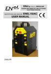
1
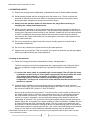
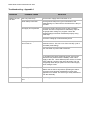
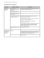
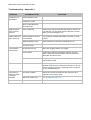
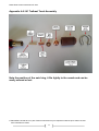
PlasmaPart Limited Instructions © 2014
USER MANUAL AND INFORMATION
CUT 80/100/120 Pilot Arc
INVERTER PLASMA CUTTER
Using Trafimet A-141 Cutting Torch
with Euro Connector
PlasmaPart Limited Instructions © 2014
Thank you for purchasing a PlasmaPart Plasma Cutter
We have included this information pack as a reference document for all users; it is intended to
provide information relating to all areas of plasma cutting from health and safety to operational tips.
We strongly advise you to keep this document with the machine.
It is important you familiarise yourself with the information within this guide, both for your safety
and ease of operation of the unit.
Important Health and Safety Information
This unit in common with all plasma cutters uses a combination of very high voltage, current and
power to generate the high temperatures required to cut metals.
Note: This is a Pilot Arc Machine and the Torch will light as soon as the trigger is pressed
irrespective of material contact.
A plasma cutter can cause injury or death if used incorrectly.
There are several hazards associated with plasma cutting:
Heat
The plasma beam created at the torch tip exits around 25,000 ˚C this presents a serious hazard if
the plasma beam were to come in contact with you. as The molten metal produced in the process
can also cause damage or injury to you if your feet or other parts of your body are not adequately
protected.
Plasma cutting should not be carried out within close proximity to any flammable substances or
materials.
Electricity
Unlike conventional welding equipment the voltage present at the torch tip when energised can be
very high presenting a risk of electrical shock or electrocution if care is not taken in use.
The torch tip could, under fault conditions be at 350V d.c. when the trigger is pressed. It will also
have a spark voltage in excess of 5000V under normal operating conditions as the machine try’s to
establish an arc.
Unlike normal mains electricity a.c. supplies this d.c. supply will cause muscle contraction rather
than spasm and may cause the hand to lock onto the supply rather than being thrown off - if you
come in contact with it.
Great care must be taken to ensure you do not come in contact with the tip or any contacts on the
machine whilst it is on.
This machine must be earthed.
The high power requirements of this machine are common with all plasma cutters.
© PlasmaPart Limited 2014 no part of these instructions may be reproduced without prior written consent
from PlasmaPart Limited
2
PlasmaPart Limited Instructions © 2014
The CUT 60/80/100/120 series of machines should only be connected to a 32A 4 wire 3 phase
(380 – 415V) supply and earth.
If in doubt please contact a qualified electrician for advice.
The tip should always be in contact with the work-piece before cutting is started and whilst cutting
is carried out - this ensures the cleanest cut, minimises the risk of molten metal being thrown
toward the operator and minimises power usage of the machine.
Compressed air
The unit requires a compressed air supply to operate. All pipe work should be kept in good
condition and checked regularly for damage.
Air at high pressure can penetrate the skin if directed onto it at close range - this can cause blood
clotting and even death. Even at a low pressures compressed air can be dangerous (even fatal) if it
is introduced into any orifices of the body.
Visible and Ultra Violet Light
The visible light generated by the arc process is not as intense as some welding operations but
can cause serious eye damage if the eyes are not protected during the cutting operation. SHADE 5
goggles are considered adequate for most purposes and are supplied with the unit. If the eyes
become sore or irritated it would be advisable to seek professional help and increase the shading
level.
The safety glasses provided are also recommended to help protect eyes from flying debris.
As with most arc welding processes skin should be protected from exposure to the ultra violet light
emitted during the cutting process.
Airborne Debris
Due to the way a plasma cutter operates airborne debris is generated and blown into the air by the
compressed air, it is strongly advised that the unit is operated in a well-ventilated environment.
It is also recommended that a mask of appropriate grade is worn to prevent ingress of fine debris
into the lungs.
Electromagnetic Radiation and Strong Magnetic Fields
In common with all welding and cutting machines the CUT 45 emits strong magnetic and
electromagnetic fields when in close proximity to the machine. Persons with pacemakers or other
artificial life support systems should remain at least 2 metres away from working machines without
the advice from a doctor of their system manufacturer’s recommendation.
© PlasmaPart Limited 2014 no part of these instructions may be reproduced without prior written consent
from PlasmaPart Limited
3
PlasmaPart Limited Instructions © 2014
Specification
Supply Voltage
3-ph AC 380 – 415V
Supply Frequency
50~60 Hz
Power requirement (at 120A)
15 KVA (Max)
Rated input current (at 120A)
32 A (Max) per phase
No-load voltage
350 V
Output current range
20-120 A
Output voltage range
88-160 V
Duty cycle @ 120 Amps Output
60% @ 40 Deg C ambient
Efficiency
Arc striking model
88%
1.0 mm (Nozzle type
dictates)
HF Start Pilot Arc
Cos φ (η)
0.93
Air pressure
90 - 110 psi
Cut Width
Instruction Notes
1. Operating environment
1.1 The CUT 60/80/100/120 machines can be operated in harsh weather conditions at
temperatures of between -10 and +40 Degrees Centigrade and a Relative Humidity of
80%.
1.2 Do not place the machine in direct sunlight or operate it in the rain.
1.3 Keep the machine dry and avoid any contact with water.
1.4 Do not use any machine in a dusty atmosphere or one containing a corrosive or explosive
gas.
1.5 If the machine will not be used for a long period of time it should be returned to its original
packing box and stored in a dry environment.
1.6 The internal fans cool the high power electronics and the entry and exit ventilators must
not be obstructed. Ensure there is sufficient space in front and behind the machine for the
forced air to circulate.
1.7 Ensure the power cable is connected to a supply which has the correct voltage and
current rating. The machines have built in electronic control to adjust for different
mains voltage over a limited range. There is a label on the back of the machine
indicating the machine setting. Units supplied to the UK will be set for 380 – 415V a.c.
which is suitable for three phase, three wire supplies and an earth connection.
1.8 Always stand the machine on a level surface to prevent the unit overturning.
© PlasmaPart Limited 2014 no part of these instructions may be reproduced without prior written consent
from PlasmaPart Limited
4
PlasmaPart Limited Instructions © 2014
2. OPERATING SAFETY
2.1 Ensure the working area is adequately ventilated and clear of all flammable materials.
2.2 Avoid physical contact with the cutting tip when the power is on. The tip could be at a
potential of 350Vdc when the torch switch is activated, this reduces during the cutting
process but both voltages can cause serious electric shock.
2.3 Always turn the machine power off and remove the plug before servicing or
changing the cutting head components.
2.4 When using the machine on site or outside ensure the grounding terminal on the back of
the machine is connected to a safety earth. This will prevent any leakage current from the
cutting circuit causing an electric shock to the operator. A cable with a cross sectional area
of 6mm2 is suitable for this purpose. Neither the torch lead or earth clamp are directly
connected to the mains earth inside the unit although the unit case is itself earthed to the
mains cable earth wire.
2.5 Do not cut containers or pipes which have held or contain gaseous or liquid fuels or
combustible substances.
2.6 Do not cut any containers or pipes which may be under pressure.
2.7 Always wear eye protection. This is to protect your eyes from both the arc and also sparks
which are produced during the cutting operation.
3. Setting up the machine
3.1 Check the cutting torch head is assembled correctly. See Appendix 4.
The Euro connector connection provides both the compressed air and cutting current to
the torch. A lead with a large crocodile clip is provided in the box for material current
return.
3.2 Connect the mains cable to a suitable high current supply. The OC light will come
on and the unit will ‘lock out’ if the mains supply at the unit drops below the lower
15% voltage limit when the ‘cut switch’ is operated. There is an internal
monitoring function inside the unit to prevent damage to the electronic
components. The Key Lock on the front of the machine must be turned on for the
machine to operate.
3.3 Connect the air regulator to the compressor with the compressor set to its maximum
pressure output. The Torches consumes approximately 230 Litres / minute ( 9 cu ft.) of air
per minute at 100PSI PSI (100psi = 6.7bar, 0.67MPa).
Set up the air pressure for the machine. To do this set the current control to 20A and turn
the mains power switch on. With the torch pointing away from you press and hold down
the control switch on the torch. Take extreme care as the torch will light when the
switch is pressed. Important - do not hold the cutting switch down in free air for
more than 10 seconds. The air control solenoid will operate and air will flow through the.
Nozzle. Adjust the air regulator for a gauge reading of 100psi (0.66 MPa, 0.66Bar) with the
air flowing through the torch. Release the switch. This set up will ensure that there is an
air pressure of 100 psi behind the cutting tip which is a good starting point for use with the
consumables and torch supplied with the unit - this can be varied according to the material
being cut, with thicker cuts and different materials requiring more or less air flow.
© PlasmaPart Limited 2014 no part of these instructions may be reproduced without prior written consent
from PlasmaPart Limited
5
PlasmaPart Limited Instructions © 2014
Do not keep the torch switch depressed for long periods without contacting the
metal. The circuit is only designed for short duration operation to initiate the arc.
Switch the machine off.
3.4 Connect the current return electrode to the material being cut. It may be necessary to
remove a small part of the surface corrosion if black steel or rusty Iron is to be cut. This
will ensure the current return electrode is making good contact with the base metal.
3.5 Observe the Duty Cycle, which is 60% at full output. If a long thick cut has been made for
say 6 minutes, allow the machine to rest for 4 minutes before making a further cut. This
will give the electronics time to cool. If machine gets too hot a monitoring circuit will
automatically stop the machine working until the unit has reached a safe level to continue.
This is indicated by the OC light illuminating on the front panel and the arc will not strike.
Leave the machine switched on to allow the fan to cool the electronics. It is necessary to
turn the machine power switch off and on again to reset the monitoring circuit.
3.6 The cutting current is maintained at the value set by the control on the front panel. The
machines cannot be overloaded; the machine has a built in electronic control circuit
which ensures the arc current flowing remains at the value set by the control knob.
3.7 The machine is now ready to cut.
4. Cutting Operation
To begin the cut place the nozzle or guide in direct contact with the material and pull the
trigger, the plasma will start and cutting can commence. Note: The material can be rusty,
painted or badly corroded, there is no need for a clean surface as the pilot arc will burn
through to the base material. Keep the nozzle in contact with the material during the cutting
operation. The air must have stopped flowing from the nozzle before the torch will light.
Wait for the air flow to stop before operating the torch switch to start the cutting operation.
4.1 The cutting current is dependent on three parameters; material thickness, speed of
cutting. (Travel speed of the torch) and standoff (distance between the cutting tip and
parent material being cut) in practice it has been found that it is easier to set a current
appropriate to the material thickness then adjust the speed of cutting to achieve the
desired result if the tip standoff is kept constant. When the correct combination is
achieved the sparks from below the material being cut will lag slightly behind the cutting
tip. Move too quickly and the sparks tend to come from above the cut and the plasma will
not penetrate all the way through the material. Moving too slowly will result in a wider cut,
heat distortion and a build-up of dross (slag) on the underside of the material. Eventually
the arc will be lost.
It is good practice to try a few cuts on scrap material where you can establish a speed of
cutting that is comfortable to achieve. The interdependence of the three parameters is
explained in more detail below.
4.2 The two terms that are commonly used to describe the quality of the cut in Plasma cutting
are Kerf (cut width) and Dross (slag).
4.3 Kerf is the width of material (perpendicular to the torch and cut axis) removed during the
plasma cutting process. Kerf is affected by two variables.
© PlasmaPart Limited 2014 no part of these instructions may be reproduced without prior written consent
from PlasmaPart Limited
6
PlasmaPart Limited Instructions © 2014
Cutting Speed
The faster travel speeds will result in a narrower kerf. The kerf will continue to narrow until
loss of penetration occurs. Slower travel speeds will result in a wider kerf until loss of arc
occurs.
Cutting Amperage
Increasing cutting amperage will result in a wider kerf. Continuing to increase current will
widen kerf until the nozzle is destroyed. Lowering amperage will result in a narrower kerf
and a more positive cut angle until penetration is lost.
Standoff is the distance maintained between the torch tip plasma exit hole and workpiece. The tips supplied with your torch have a built in standoff between the plasma exit
and work piece and have been designed to remain in contact with the material being cut.
If the standoff is increased during cutting the machines have an arc voltage feedback
system which will increase the arc voltage as the standoff distance increases and widen
the kerf. Continuing to increase standoff will eventually lead to loss of cut. The unit will
electronically maintain the constant set current if the standoff distance is changed.
4.4 Dross (slag) is the excess material that spatters and builds up on the underside of the
material as you cut.
Dross occurs when the operating procedure and technique is less than optimal. It will
require practice and experience to obtain cuts without dross. Although less than optimal
cuts will contain dross, it is relatively easy to remove by breaking it off using pliers or
chipping off with a chisel.
A combination of factors contributes to the build-up of dross. These include material type,
material thickness, amperage used for the cut, speed of the torch across the work-piece,
condition of the torch tip, air pressure, etc. Do not use more output current than is
necessary and adjust speed of cut to minimise dross build-up on underside of cut. Try
carrying out further experiments adjusting current and speed to minimize dross and obtain
a satisfactory result. When cutting aluminium a lower air flow rate is used to obtain a
cleaner cut.
4.5 Cutting tip angle. It is important to keep the cutting tip near to vertical in the direction of
travel and also at right angles to the direction of the cut. Basically the plasma will cut in
the direction the tip is pointed. This can be used to advantage if a weld preparation is
needed on the material being cut. When reaching the end of the cut ‘tip’ the torch slightly
away from the end of the material to sever the final bridge. The same technique in the
opposite direction can also be useful when starting the cut.
Please note that not all A-141 Plasma Torch consumables available are of the same
design and dimensions. The torch, torch cable and spares provided with this unit and
available from us have all been selected, inspected and tested to ensure they meet our
required specification. Some cutting tips available from other suppliers will require a
standoff to be maintained in use and other consumable components may require a higher
air pressure to function correctly; some parts available will not function correctly at all.
5. Maintenance
5.1 Before use
∙ Check the power connection and air supply hose for damage. Repair or replace any
© PlasmaPart Limited 2014 no part of these instructions may be reproduced without prior written consent
from PlasmaPart Limited
7
PlasmaPart Limited Instructions © 2014
damaged items before use.
∙ Check the condition of the shroud, cutting tip, electrode and swirl ring. Replace
as necessary.
∙ Check the torch is assembled correctly for the cutting current to be used.
∙ Check the ground clamp connection and cutting torch cables for damage. Repair or
replace as necessary. Ensure these are tight to their respective connections on the unit.
5.2 During use
∙ Regularly check the cutting tip and shroud for a build-up of dross (slag) from
the cutting process.
∙ Brush off any build up with the wire brush provided. Avoid enlarging the hole in the tip
through which the Plasma exits.
∙ Always switch off the machine before touching the cutting tip or dismantling the torch.
5.3 After use
∙ Disconnect earth lead and torch from the unit
∙ Dismantle the torch and clean the ceramic cup, electrode, swirl ring and cutting tip.
The electrode and cutting tip can also be cleaned with 120 grit wet and dry paper.
∙ Re-assemble the torch and store items in a safe place. The shroud is easily damaged,
if it comes into sharp contact with a hard surface.
This information should be considered important and you must understand it before
using the CUT 60/80/100/120120 plasma cutters for your own and others safety.
If there is something you don’t understand please contact PlasmaPart Ltd. for
clarification. We are here to help!
© PlasmaPart Limited 2014 no part of these instructions may be reproduced without prior written consent
from PlasmaPart Limited
8
PlasmaPart Limited Instructions © 2014
Declaration of Conformity
The undersigned Company - PlasmaPart Ltd.
Unit 7, Waldron Court, Prince William Road, Loughborough, Leicestershire. LE11
5GD. Declares that the product identified and described on this page has been
tested by their supplier and complies with standard EN 60974-7
in accordance with the requirements of directive
EEC 73/23 Low Voltage Directive
Certificate valid until 20.11.14
Portable Appliance Testing
This equipment is tested in accordance with the IEE Code of Practice - 3rd Edition Inspection and Testing of Electrical Equipment - by a person holding recoginised
qualifications using calibrated test equipment as part of PlasmaPart Ltd. PreDespatch QA procedures.
© PlasmaPart Limited 2014 no part of these instructions may be reproduced without prior written consent
from PlasmaPart Limited
9
PlasmaPart Limited Instructions © 2014
Troubleshooting - Appendix 1
PROBLEM
Plasma arc will
not start
POSSIBLE CAUSE
SOLUTION
Unit not powered up
Check mains supply and on/off switch is on
Work clamp connection
Check ground clamp has a good connection to the
material being cut, clean surface of material if it is dirty or
corroded
Air supply is low pressure
Check air is flowing from the torch tip with cut switch
pressed. Check the compressor is maintaining 75psi at
the gauge while cutting is in progress. Check the
regulator fittings have been assembled properly using
PTFE tape.
Check the cutting tip is not blocked by dross
OC Light on front panel of
unit comes on
Switch machine off and wait about 2-3 minutes, Switch
machine back on. This can occur if the unit duty cycle is
exceeded (overheating)
Use 32A cable for power lead extensions.
Try operating the cutter at 20A set current, if this is OK
then there is a problem with the stability of the mains
supply to the unit. Use a different power source or thicker
mains cable to connect to the unit mains lead. The unit
will typically draw 32A per phase from the mains supply
when cutting at 120A.
Air Supply / Torch
The torch will not start if air is coming out of the nozzle.
Wait for the air flow to stop before operating the switch.
Check the torch has been assembled correctly. See
Appendix 4 for details. The swirl ring is easily missed out
from the assembly.
Technical problem with the
unit
[email protected]
PlasmaPart Limited Instructions © 2014
Troubleshooting - Appendix 2
PROBLEM
Plasma arc
stops while
cutting
POSSIBLE CAUSE
Hand too tense,
inadvertently releasing the
cut switch
SOLUTION
Hold the torch lightly against the material being cut, don't
push down. Try and relax the hand.
Cutting speed too slow
Torch moved too far away
from material
Compressor unable to keep
up with air demand
Check air pressure gauge reading when cut stops.
Check air pressure is 100psi
Check torch lead connections at unit and torch are tight.
Check torch hose is undamaged.
Check torch 'O' ring is intact and undamaged
Check shroud for fractures.
Check compressor, give the compressor time to recover if
making long cuts when using a smaller compressor.
Check the regulator fittings have been assembled
properly using PTFE tape.
Sparks are
shooting upward
not downward
through the
material
Technical problem with the
unit
[email protected]
Plasma arc not piercing
material
Torch travel speed too fast
Check grounding clamp is making a good connection to
the material being cut and is tightly connected at the unit.
Clean a patch of material for clamp if rusty
Increase current
PlasmaPart Limited Instructions © 2014
Troubleshooting – Appendix 3
PROBLEM
Insufficient cut
penetration
POSSIBLE CAUSE
SOLUTION
Cutting speed too fast
Insufficient current
Worn or damaged torch
electrode or tip.
Beginning and
end of cut not
severed
Torch positioning
Tilt the top of the torch towards the direction of travel as
you start the cut. Tilt it away from the direction of travel
when you are finishing the cut.
Dross build up on
parts of the cut
Cutting speed too slow or
not consistent
Try keeping a constant and steady cut speed for a set
current
Material getting too hot
Allow material to cool before continuing the cut
Current too high
Consumables
wear quickly
Air pressure too low
Re-check gauge pressure is at 100psi
Torch position
Tilt the top of the torch toward the direction of travel
when cutting the thickest material. This will reduce the
blow back into the torch tip.
Poor maintenance
Frequently clean the dross off the cutting tip using the
wire brush provided.
Cut is not vertical
Torch position
The torch cuts in the direction that the plasma arc is
pointed. Keep the torch vertical for a vertical cut. The tip
can be angled to produce a weld prep if this is required
on the material being cut.
Torch will not
switch off when
cut switch
released
Cut switch problem
Check the cut switch contacts at the machine end of
cable for correct on/off circuit
Electronic Fault in unit
[email protected]
PlasmaPart Limited Instructions © 2014
Appendix 4 A-141 Trafimet Torch Assembly
Note the position of the swirl ring, it fits tightly to the nozzle and can be
easily missed or lost.
© PlasmaPart Limited 2014 no part of these instructions may be reproduced without prior written consent
from PlasmaPart Limited
13
PlasmaPart Limited Instructions © 2014
SAFE SYSTEM OF WORK – PLASMA CUTTING
(Please note: This is a generalised SSW and it should adapted to suit your own operations and
systems)
RISKS
There are significant Health and Safety risks that can occur from plasma cutting processes, these
are detailed if the Risk Assessment and comprise the following:
Intense ultra violet and infrared radiation
Fumes from the cutting process
Heat
Electric shock
Electromagnetic Radiation
Ignition of combustible material
Unauthorised use
Danger from pipes, vessels and cables
SAFE SYSTEM OF WORK
INTENSE ULTRA VIOLET AND INFRA RED RAYS
The operator should always wear suitable eye protection and ensure other observers’ eyes are also
protected.
Post signs to warn other people of the visual danger from the operation or work in a restricted
area.
FUMES
Only use the equipment in a well-ventilated area.
HEAT
Use appropriate gloves, clothing and footwear during all cutting processes.
Point the torch into a safe area before pulling the trigger. The Pilot Arc will start instantaneously
and cause severe burns if it made contact with exposed or covered skin.
ELECTRIC SHOCK
Always turn the machine power off before servicing the cutting torch.
Check the mains plug and cable for cuts or burns before the power is turned on. Report any defects
before using the machine
© PlasmaPart Limited 2014 no part of these instructions may be reproduced without prior written consent
from PlasmaPart Limited
14
PlasmaPart Limited Instructions © 2014
Ensure colleagues are aware of how to deal with a person suffering from electric shock.
ELECTROMAGNETIC RADIATION
Any person fitted with a heart pacemaker must not be permitted to be closer than 2m of any
operational electrical cutting equipment.
IGNITION OF COMBUSTIBLE MATERIAL
Combustible materials are not to be used, stored or allowed to accumulate in the welding/cutting
area. Sparks and molten metal from the cutting process can travel a long way.
UNAUTHORISED USE (CUT 80/100/120 only)
Always switch the machine OFF and turn off and remove the safety lock key before leaving the
machine unattended. The torch will not light with the key switch set off.
DANGER FROM PIPES, VESSELS AND CABLES
Ensure any pipework to be cut is free from chemical contamination. Some chemical elements
could explode or create noxious fumes when heated to plasma cutting temperatures.
Ensure any vessel or cylinder to be cut does not contain any flammable gas, fuel or pressure before
cutting.
Avoid working near to cables which may be live.
Do not cut cable which has insulation, burning insulation could create noxious fumes.
Keep the machine power cables and torch power connection away from the cutting area.
© PlasmaPart Limited 2014 no part of these instructions may be reproduced without prior written consent
from PlasmaPart Limited
15
PlasmaPart Limited Instructions © 2014
RISK EVALUATION AND PRECAUTIONS FOR WELDING AND CUTTING OPERATIONS
(Please note: This is a generalised Risk Assessment and it should adapted to suit your
own operations and systems)
The potential risks from welding or cutting operations are identified as
follows:
1.
2.
3.
4.
5.
6.
7.
Intense ultra violet radiation and Infrared rays
Fumes
Heat
Electric Shock
Electromagnetic radiation / Strong magnetic fields
Ignition of combustible material
Compressed Air
The following safety precautions have been taken by the Company to overcome or
mitigate the risks involved with electrical welding or cutting operations:
INTENSE ULTRA VIOLET RADIATION AND INFRA RED RAYS
To protect from intense visible and ultraviolet light safety glasses or a helmet will be provided with
an appropriate filter lens to reduce the light intensity and protect the face and eyes from the heat
generated in the processes.
FUMES
A downdraught ventilation and filtration cabinet should be used to remove sparks and welding
fumes and gasses from the immediate vicinity of the operator.
HEAT
Appropriate clothing and gloves are provided and will be worn during all welding and cutting
processes.
ELECTRIC SHOCK
Whilst the effect of a shock from the high voltage is unpleasant it is unlikely to be fatal. The power
supply to the machine should be switched off before adjustment or servicing is carried out on the
torch to prevent accidental contact with the spark or cutting power source.
Most welding plant is classified as Class 1 Moveable Equipment and in an industrial environment
there is a legal requirement that user checks are made each time before the equipment is used.
ELECTROMAGNETIC RADIATION
Regulations state that any person fitted with a heart pacemaker or other life support device will
not permitted to be closer than 2 metres of any operational welding or cutting equipment.
A warning sign to this effect is included on entry doors to the welding/cutting area.
IGNITION OF COMBUSTIBLE MATERIAL
Combustible materials are not to be used, stored or allowed to accumulate in the welding/cutting
area.
© PlasmaPart Limited 2014 no part of these instructions may be reproduced without prior written consent
from PlasmaPart Limited
16
PlasmaPart Limited Instructions © 2014
USE OF COMPRESSED AIR
The unit requires a compressed air supply to operate. All pipe work should be kept in good
condition and checked regularly for damage.
Air at high pressure can penetrate the skin if directed onto it at close range - this can cause
blood clotting and even death. Even at a low pressures compressed air can be dangerous
(even fatal) if it is introduced into any orifices of the body.
© PlasmaPart Limited 2014 no part of these instructions may be reproduced without prior written consent
from PlasmaPart Limited
17