1
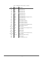
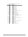
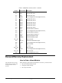
GEI-100269 *(,QGXVWULDO6\VWHPV Auxiliary Genius Bus Interface Module IS215GBIAH_A_ _ Safety Symbol Legend Indicates a procedure, practice, condition, or statement that, if not strictly observed, could result in personal injury or death. Indicates a procedure or condition that, if not strictly observed, could result in damage to or destruction of equipment. Note Indicates an essential or important procedure or statement. These instructions do not purport to cover all details or variations in equipment, nor to provide every possible contingency to be met during installation, operation, and maintenance. If further information is desired or if particular problems arise that are not covered sufficiently for the purchaser’s purpose, the matter should be referred to GE Industrial Systems. This document contains proprietary information of General Electric Company, USA and is furnished to its customer solely to assist that customer in the installation, testing, operation, and/or maintenance of the equipment described. This document shall not be reproduced in whole or in part, nor shall its contents be disclosed to any third party without the written approval of GE Industrial Systems. Table of Contents Safety Symbol Legend .............................................................................................1 Functional Description ............................................................................................1 LED Indicators.........................................................................................................3 Genius Bus................................................................................................................3 Genius Bus Connections..........................................................................................3 Genius Bus Performance .........................................................................................5 Data Mapping ..........................................................................................................6 Drive Parameters .....................................................................................................6 Set Parameters Using the Toolbox...........................................................................7 Set Parameters Using the Drive Keypad..................................................................8 Series Six Genius LAN............................................................................................9 LAN Status and Faults...........................................................................................1 0 Application Data ....................................................................................................11 Renewal/Warranty Replacement .........................................................................18 How to Order a Board/Module ..............................................................................18 Module, Motherboard, Daughterboard ..................................................................2 0 How to Replace the Board/Module........................................................................20 Functional Description The IS215GBIA Auxiliary Genius Bus Interface Module (GBIA) models the Innovation Series drive as an I/O block on the Genius bus (see Figure 1), providing seamless integration between the drive and controller. • Discrete commands and references are sent from the controller (typically a PLC) to the drive. • Selected discrete and word variables are fed back from the drive to the controller. The GBIA module provides either an integer or floating-point variable map between the drive and controller. A floating-point map is defined with all of the variables in engineering units, the integer map requires certain variables to be scaled. Configuration of the interface is done with either the local keypad or the Control System Toolbox (see Figure 2). Genius is a trademark of GE Fanuc Automation North America, Inc. Innovation Series is a trademark of General Electric Company, USA. The GBIA module is made up of an IS200BLIG LAN Interface-Genius Board (BLIG) and an IC660ELB912 µGENI Network Interface Board (µGeni). The module connects to the IS200CABP Cable Assembly Backplane Board (CABP) in the drive board rack. The GBIA module interfaces to the drive through its backplane connector, P8. All power and digital I/O signals are routed through this connector. The µGeni board mounts to the BLIG board on four standoffs (to create the GBIA module) and communicates to it through connectors P1 and P2. All digital address, data, and control signals between the two boards are interfaced via P1. Power is supplied to the µGeni board through P2. The GBIA module interfaces to the Genius bus via a four-pin connector located on the module's faceplate. Two LED indicators on the module's faceplate provide visual indications of module and Genius communications status. For more information on the µGeni board, refer to GE Fanuc publication GFK0845. Genius CPU Series 90-30 Genius Bus Genius I/O blocks Innovation Series drive control racks Figure 1. Genius Bus System Control System Toolbox Keypad on cabinet door RS-232 Figure 2. Configuration Devices 2 • Auxiliary Genius Bus Interface Module IS215GBIAH_A_ _ GEI-100269 LED Indicators Two LED indicators, OK (DS1_A2) and COMM OK (DS1_A1), are located on the module’s faceplate and provide visual indications of module and Genius bus communications status. A third LED (DS2) is located on the module’s surface and indicates the P5 power supply status (ON when P5 is present). When the module is functioning properly with no known faults, the green OK LED lights continuously. If there is a fault, this LED flashes a fault code (see Table 1). The green COMM OK LED provides Genius bus communications status information. This LED lights continuously when there are no known Genius I/O faults. Genius Bus Input/Output (I/O) applications of the Genius bus are typically configured with one controller, 1-30 I/O devices (Genius I/O blocks, Field Control I/O stations, drives, etc.), and one node reserved for the hand held monitor. The Genius bus operates asynchronously with the execution of control logic. Genius Bus Connections The GBIA module interfaces to the Genius bus via a four-pin connector labeled GENIUS on the faceplate. There are two methods of physically connecting the module to the Genius bus: • Bring the Genius bus directly to the GENIUS connector (TB1) on the faceplate of the module (see table below). • Install an interposing terminal block on the DIN rail in the drive cabinet. Note The GBIA module’s faceplate screws must be tight because these tie the module to ground. Pin No. For more information and cable types, see GE Fanuc publication GEK-90486F-1 Genius I/O Systems and Communications User’s Manual (Chapter 2, The Communications Bus). GEI-100269 Label Description 1 SHD OUT Shield to ground 2 SHD IN Shield to ground through a 0.1 µf capacitor 3 SER2 10 V differential signal on the Genius bus for data 4 SER1 10 V differential signal on the Genius bus for data The Genius bus must be terminated on each end by an impedance that is correct for the cable type used. The impedance will be 75, 100, 120, or 150 ohms. To terminate the end, connect the impedance (resistor) from SER1 to SER2. Auxiliary Genius Bus Interface Module IS215GBIAH_A_ _ • 3 À To connect Genius bus to GBIA module faceplate (see Figure 3) From the previous device: 1. Connect Genius wire SER1 to SER1. 2. Connect Genius wire SER2 to SER2. 3. Connect Shield In to SHD IN. To the next device: 4. Connect SHD OUT to Shield Out. 5. Connect SER1 of one device to SER1 of the next device. 6. Connect SER2 of one device to SER2 of the next device. Connect so that one end of the shield is tied directly to ground and the other end is tied to ground through a capacitor. GBIA Module Faceplate Connector Genius Bus Shield Out Shield In SER2 From Previous Device SER1 SER2 SER1 Shield In Shield Out SER2 SER2 SER1 To Next Device SER1 Figure 3. Direct Connection to Genius Bus À To connect the Genius bus to a remote terminal strip (see Figure 4) Terminal strip to next device: 1. Connect one shield to chassis. 2. Connect the other shield through a 0.1 microfarrad capacitor to chassis. Terminal strip to GBIA module faceplate: 3. Run two twisted pairs to the GBIA module. 4. Tie the shield of wires A and B running to/from the GBIA module to the chassis at the terminal strip. (Leave the GBIA module end of the shield open.) 4 • Auxiliary Genius Bus Interface Module IS215GBIAH_A_ _ GEI-100269 GBIA Module Faceplate Connector Remote Terminal Strip Shield Out 0.1 uF Chassis Wire A Shield In Serial 2 (wire A) Wire B Serial 1 (wire A) Serial 2 (wire B) Serial 1 (wire B) Figure 4. Remote Terminal Strip Genius Bus Connection Genius Bus Performance To specifically calculate the Genius bus sweep rate, refer to the Genius I/O Systems and Communications User Manaual (GEK-90486F-1). A detailed procedure is provided with equations. GEI-100269 On the Genius bus, the drive functions like a Genius I/O block. A controller sends control bits and setpoints to the drive on each bus scan using a directed message. The drive broadcasts its feedback bits and feedback variables back to the controller once per bus scan. In controlling industrial processes, the frequency at which the drive and controller can exchange information is important. There are several factors that determine this performance over the Genius bus as shown in the following table: Genius Bus Performance Factor Description Control logic sweep rate Time required for a sweep of the control logic being executed in the controller (typically measured in milliseconds). Configured baud rate of the bus Baud rate of the bus is configurable as a parameter for each device. Types of devices on the bus The contribution of each device to the bus sweep rate varies with the quantity of I/O data being exchanged with the controller. Each drive contributes 4ms to the bus sweep time at a configured baud rate of 157K. Quantity of devices on the bus As the number of devices on the bus grows, so does the bus sweep rate. Auxiliary Genius Bus Interface Module IS215GBIAH_A_ _ • 5 Data Mapping It is not possible to configure the drive through the Genius interface. The drive is configured through its keypad or by the Control System Toolbox (toolbox). Once configured, the drive exchanges a fixed set of variables with the controller during each Genius bus cycle as follows. • Variables sent to the drive are defined as references • Variables retrieved from the drive are defined as feedbacks. The variables available are specified in the drive documentation (see Table below). Pattern Publication No. Drive/Publication Type ACDCF-G GEH-6393 Innovation Series Low Voltage Reference and Troubleshooting ACDCF-S GEH-6394 Innovation Series Low Voltage Reference and Troubleshooting ACDCF-V GEH-6395 Innovation Series Low Voltage Reference and Troubleshooting ACCBN-A GEH-6396 Innovation Series Low Voltage Reference and Troubleshooting ACCBR-A GEH-6397 Innovation Series Low Voltage Reference and Troubleshooting ACMVAC4-G GEH-6383 Innovation Series Medium Voltage – GP Type G Drives Users Guide ACMVACR-G GEH-6131 Innovation Series Medium Voltage – GP Type H Drives Users Guide The drive treats all internal variables, except for bits, as floating point quantities. The drive has two fixed variable interface maps to provide variable data transfer to and from a network: • One map contains the drive’s references and feedbacks in the form of 16-bit integers. • The other map presents the same information in 32-bit IEEE floating point format. Only one of the two maps is available at any given time, and the selected map can only be changed through the drive’s keypad or the toolbox by modifying the LAN Page Format parameter. Refer to the specific drive’s documentation for instructions on selecting the variable interface map and for descriptions of each variable. The integer format of the variable interface map consists of 17 words of reference and 17 words of feedback. The first two words of reference contain 32 bits, as do the first two words of feedback. The remaining 15 words of reference and of feedback contain signed integer variables. The floating point format of the variable interface map consists of 16 references and 16 feedbacks. Each reference and feedback is a double word (4-byte) entity. The first double word of references contains 32 bits, as does the first double word of feedbacks. Each of the remaining 15 references and 15 feedbacks is in IEEE floating point format. Internally, the drive stores these floating point values in Little Endian (Intel) format. This format applies to each double word of the map, including the double word containing the bits. Drive Parameters Genius LAN parameters are located in the toolbox Outline View. Parameters can differ according to the product loaded. All of the GBIA module’s configuration parameters are stored in the drive and loaded into the GBIA module when the drive is powered up or reset. The parameters cannot be modified through the Genius LAN and must be configured through the drive’s keypad or the Control System Toolbox (toolbox). The toolbox uses an RS232C connection to download parameters to the drive. 6 • Auxiliary Genius Bus Interface Module IS215GBIAH_A_ _ GEI-100269 The following parameters configure the application interface: • Network interface (Net_Type) • Lan frame time (Lan_Frm_Tm) • Lan fbk avg time (Lan_Avg_Tm) • Lan page format (Lan_Pag_Fmt ) • Lan cmd inhibit (Inh_Lan_Cmd) • Lan trips inhibit (Inh_Lan_Trp) • Lan heartbeat time (Lan_Htbt_Tm) Additional LAN-specific parameters (LAN parameter 01 − 16) are required to configure direct LAN interfaces. These parameters are referred to as generic LAN parameters in the core drive product. Set Parameters Using the Toolbox À To download and modify parameters 1. From the toolbox Outline View, double-click on the file name, such as ISD1. The Edit Innovation Series Drive dialog box displays. 2. From the Network Interface drop-down box, select Genius. Click OK. 3. Download parameter names by selecting Device menu, Download to Drive and Keypad (DDI) Menus. (You must go online to download parameters.) 4. Expand items in the Outline View and modify parameters as follows: From the Outline View, click to expand items and select parameters. For example, Main Menu, Network Communications, Configuration & Health, and Parameters. GEI-100269 Auxiliary Genius Bus Interface Module IS215GBIAH_A_ _ • 7 5. 6. Select and load the following parameters: • LAN Board Options – Set the value to 0 • Genius Device Number – Enter the desired device number • Genius Baud Rate – Set the Baud Rate Selection Number for the desired baud rate. Baud Rate Selection Numbers are: 0 = 153.6 Kb extended 1 = 38.4 Kb standard 2 = 76.8 Kb standard 3 = 153.6 Kb standard • Genius Refr Address – Set the Genius Reference Address if required (see Series Six Genius LAN section) From the Device menu, select Reset to Drive and then Hard Reset. This hard reset must be performed for the changes to take place. Set Parameters Using the Drive Keypad The Genius LAN parameters have both a generic/short name and a specific/long name. • Specific/long parameter names that display in the toolbox will display on the keypad. • Generic/short parameter names display with no toolbox. À To download and modify parameters (see Figure 5) Note The keypad displays the drive’s status when the drive is powered up. The Menu key must be pressed to display the Main Menu items. 1. Press the Menu key (in Navigation portion of the keypad) to display the Main Menu. 2. Press the Down Arrow key to highlight Network Communications, then press the Enter key to display the selections. 3. Verify that Configuration & Health is highlighted, then press the Enter key to display the selections. 4. Verify that Parameters is highlighted, then press the Enter key to display the selections. 5. Verify that Network Interface is highlighted, then press the Enter key to display the selections. 6. Press the Down Arrow key to highlight DRIVENET, then press the Enter key to enable the drive’s interface to the GBIA module. 8. Press the Down Arrow key to highlight LAN Parameter 1 or LAN Network Enabled and set its value to 1 to enable the GBIA module for Genius LAN operation. 9. Press the Down Arrow key to highlight LAN Parameter 2 or LAN Board Options and set its value to 0. 8 • Auxiliary Genius Bus Interface Module IS215GBIAH_A_ _ GEI-100269 GE Innovation Series DISPLAY – Provides both analog and digital representations of drive functions, values, and text-based menus. KEYPAD – Organized into two functional groups: Navigation keys and Drive Control keys. RUN and STOP keys are placed to the side for easy access. RPM feedback 0.0 RPM Motor current 0.00 A rms Motor voltage 0.00 V rms Motor power 0.00 KW DRIVE HEALTH ICONS: 0% -150 +150 Heartbeat Control State 0% 75 +150 0% 75 +150 Fault State Drive Direction Motion -150 0% +150 Drive Controls Navigation Status Reset Faults Menu Remote Local RUN Jog STOP Speed Escape Enter Figure 5. Example DDI (Keypad) 10. Press the Down Arrow key to highlight LAN Parameter 3 or Genius Device Number and set its value to the desired device number. 11. Press the Down Arrow key to highlight LAN Parameter 4 or Genius Baud Rate and set the Baud Rate Selection Number for the desired baud rate. Baud Rate Selection Numbers are: 0 = 153.6 Kb extended 1 = 38.4 Kb standard 2 = 76.8 Kb standard 3 = 153.6 Kb standard 12. Press the Down Arrow key to highlight LAN Parameter 5 or Genius Refr Address and set the Genius Reference Address if required (see Series Six Genius LAN section). 13. Press the Reset Faults and Stop keys simultaneously to initiate a hard reset of the drive. This must be done for the changes to take effect. Series Six Genius LAN Certain older versions of the Series Six Genius LAN require the address of the Genius block (not the drop or block number). The drive must be coded with the Genius I/O address in order for the µGeni board to communicate on the Series Six Genius LAN. The parameter Genius Refr Address holds the address information for the Series Six Genius LAN. The Series Six interprets the information in this parameter as the address of the I/O to be populated and the type of I/O. The most significant bit determines if the I/O is loaded into parameter memory or the regular I/O table. GEI-100269 Auxiliary Genius Bus Interface Module IS215GBIAH_A_ _ • 9 • If the most significant bit of Genius Refr Address is cleared (0), then the outputs of the drive are directed to the input table of the Genius controller. The beginning address is specified by the fifteen least significant bits of Genius Refr Address. The drive inputs come from the output table of the Genius controller beginning at the same address specified by the fifteen least significant bits of Genius Refr Address. • If the most significant bit of Genius Refr Address is set (1), then the outputs from the drive are directed to the register table beginning at the address specified by the fifteen least significant bits of GREFRN. The drive inputs come from the information in the registers immediately following the output registers. LAN Status and Faults Two levels of validation are available to the drive: LAN watchdog function determines the status of the connection between the DSPX board and the GBIA module. This is done in the form of a handshake protocol. The actions of the watchdog function are limited to alarms and status variables, although the status information is also used for interface management. The watchdog offers no information as to the status of the LAN connection beyond the immediate interface. LAN heartbeat function provides a means by which to loop back a signal between the drive and any level in the LAN hierarchy such that a higher-level controller can validate the entire connection pathway, including the drive itself. Drive status information is conveyed to the user and/or application by status signals and fault declarations. The drive can be configured to generate a trip or alarm if the heartbeat reference signal fails to transition within a configurable period of time. The first bit in the drive’s reference map is used as a heartbeat from the master controller to the drive. The master controller is expected to continually toggle this heartbeat reference. Variables sent to the drive are defined in the drive’s reference map. Variables retrieved from the drive are defined in the drive’s feedback map. If the drive is accepting references from the Genius bus and the Genius bus itself fails (the master controller fails or the Genius bus cable is disconnected), the drive continues to use the last references received from the Genius bus. If the drive is accepting references from the Genius bus, the drive faults if there is no transition of the heartbeat reference within the time period specified by the LAN Heartbeat Time parameter (this parameter must not be zero). The first bit in the drive’s feedback map is used as a heartbeat from the drive to the master controller. The drive always writes the heartbeat feedback to the same state as the heartbeat reference. Thus, the master controller can monitor the status of the communication with the drive by continually toggling the heartbeat to the drive and monitoring the heartbeat from the drive. Note One easy way for a PLC (used as a master controller) to generate a heartbeat to the drive is to simply invert the heartbeat from the drive and send that value back to the drive. The following signals determine LAN health and declare LAN faults: • LAN connection OK (Lan_OK) • LAN commands OK (Lan_Cmds_OK) • Heartbeat ref, LAN (Lan_Htbt_Ref) • Heartbeat fbk, LAN (Lan_Htbt_Fbk) 10 • Auxiliary Genius Bus Interface Module IS215GBIAH_A_ _ GEI-100269 The following faults are associated with the LAN interface: • LAN heartbeat trip (Lan_Hb_Trp) • LAN heartbeat alarm (Lan_Hb_Alm) • LAN watchdog alarm (Lan_Wd_Alm) • LAN trip request (Lan_Trp) • LAN alarm request (Lan_Alm) Application Data The GBIA module has no fuses, user adjustable hardware, or user testpoints. • Jumper JP1 is open and should not be inserted by the user. • Testpoints TP1 and TP2 and connectors J1 and J2 (BLIG board) are for engineering test use only and not defined in this document. The GBIA module has five plug connectors (BLIG board), one backplane connector (P8), and five LED indicators. See Figure 6 for a module faceplate diagram and Figure 7 for a BLIG board layout diagram that show the locations of these components. See Figure 8 for the location of the GBIA module in the board rack. Note Two LED indicators are also present on the µGeni board. These LEDs are not visible when the GBIA module is mounted in the board rack and are not defined in this document. Connector P3 is not used and is not defined in this document. Refer to the following tables for complete descriptions: Table GEI-100269 Description 1 OK LED fault codes 2 TB1 Genius bus connector 3 P1 µGeni board interface connector 4 P2 µGeni board power supply connector 5 P8 GBIA module backplane connector Auxiliary Genius Bus Interface Module IS215GBIAH_A_ _ • 11 LED Indicator GE Motors & Industrial Systems LED Indicator Genius LAN Connector Figure 6. GBIA Module Faceplate JP1 DS1 P2 J2 J1 P3 TP1 TP2 TB1 P8 P1 IS200BLIGH1A Figure 7. GBIA Module (BLIG Board) Layout Diagram 12 • Auxiliary Genius Bus Interface Module IS215GBIAH_A_ _ GEI-100269 CABP BAIA RAPA_B BIC_ 44 DSPX (option) 44 ACL_, GBIA, or PBIA (option) BPI_ 68 68 50 CABP Figure 8. GBIA Module Location in the Board Rack Table 1. OK LED Fault Codes for GBIA Module Flashes Fault No. Fault Name Description 1 1 FLT_BOOTCKSM GBIA boot code failed the initialization checksum test. 2 2 FLT_FLSHCKSM GBIA module needs a flash download because the flash checksum failed or a flash download header was received and now the GBIA module is ready for a flash download. 3 3 FLT_FLDNFAIL Flash download to the GBIA module has failed. 4 4 FLT_FLDNGOOD Flash download to the GBIA module is good and the GBIA now needs a hard reset (this is true after a flash download). 5 5 FLT_LINTNRAM GBIA (internal to the processor) RAM failed the initialization testing. 6 6 FLT_LXTRNRAM GBIA (external to the processor, internal to the board) RAM failed the initialization testing. 7 7 FLT_LINTTMRS Internal GBIA processor timers failed the initialization testing. 8 8 FLT_LDPRTRAM Dual port RAM memory failed the initialization testing. 9 9 FLT_LXC5202_ XC5202 (programmable gate array) serial download failed. 10 10 FLT_LSTCKOVR GBIA stack has overflowed. 11 11 FLT_LDSPWD0G DSPX board watchdog timer failed (DSPX did not update the watchdog timer within the specified time interval) 12 12 FLT_LCLNACTV GBIA firmware active bit was mistakenly cleared. This bit should always be set while the GBIA is active (operational). 13 13 FLT_GENINIT Genius initialization fault 14 14 FLT_GENIRTM Genius run time fault 15 15 FLT_PROFINI Profibus-DP initialization fault 16 16 FLT_PROFIRT Profibus-DP run time fault GEI-100269 Auxiliary Genius Bus Interface Module IS215GBIAH_A_ _ • 13 Table 2. Connector TB1, Genius Bus Connection to GBIA Module Pin No. Nomenclature Description 1 SHD OUT Shield to ground 2 SHD IN Shield to ground through a 0.1 µf capacitor 3 SER2 10 V differential signal on the Genius bus for data 4 SER1 10 V differential signal on the Genius bus for data Table 3. Connector P1, I/O Between the BLIG Board and µGeni Board Pin No. Nomenclature Description 1 DCOM Digital common ground 2 P5 +5 V dc 3 DCOM Digital common ground 4 P5 +5 V dc GA0 – GA13 Genius LAN address lines 0 – 13 19 P6 (7) Genius LAN setup signals 20 P6 (6) Genius LAN setup signals 21 P6 (5) Genius LAN setup signals 22 P6 (4) Genius LAN setup signals 23 P6 (3) Genius LAN setup signals 24 P6 (2) Genius LAN setup signals 25 P6 (1) Genius LAN setup signals 26 P6 (0) Genius LAN setup signals 27 N/C Not Connected 28 0GRST Genius reset line 29 0GENINT Genius interrupt 30 0RD Read line to Genius 31 0WRL Genius LAN write strobe 32 0MCS1 Genius LAN board select 33 0GENRDY Genius LAN ready signal 34 MONO For factory use only GD0 – GD7 Genius LAN data signals (D0 – D7) 43 0GIOK Micro Genius board OK 44 0COMOK Genius LAN communication OK N/C Not Connected 49 GEN1X2 Genius LAN connection 50 GEN1X1 Genius LAN connection 5 − 18 35 − 42 45 − 48 14 • Auxiliary Genius Bus Interface Module IS215GBIAH_A_ _ GEI-100269 Table 4. Connector P2, Power Supply to µGeni Board Pin No. Nomenclature Description 1, 3, 5, 7, 9 P5 + 5 V dc (± 10%) power supply input to µGeni board 2, 4, 6, 8, 10 DCOM Digital common Table 5. P8 Backplane Connector, Row A Pin No. Nomenclature Description A1 P5 +5 V dc digital power source A2 XD(0) Transmit data, line 0 A3 XD(4) Transmit data, line 4 A4 DCOM +5 V dc digital power return (digital common) A5 XD(8) Transmit data, line 8 A6 XD(12) Transmit data, line 12 A7 XD(16) Transmit data, line 16 A8 XD(20) Transmit data, line 20 A9 XD(24) Transmit data, line 24 A10 XD(28) Transmit data, line 28 A11 XA(0) Transmit address, address 0 A12 DCOM +5 V dc digital power return (digital common) A13 XA(4) Transmit address, address 4 A14 XA(8) Transmit address, address 8 A15 XA(12) Transmit address, address 12 N/C Not Connected A18 0X_CS Dual port RAM chip select A19 0X_CS_SPR Spare 0X_CS (not connected) A20 DCOM +5 V dc digital power return (digital common) A21 0XRST Module reset A22 P5 +5 V dc digital power source A23 − A27 N/C Not Connected A28 DCOM +5 V dc digital power return (digital common) A29 CHASSIS Chassis ground A30 KTX_ACL Keypad transmit (Not Connected) A31 N/C Not Connected A32 P5 +5 V dc digital power source A16, A17 GEI-100269 Auxiliary Genius Bus Interface Module IS215GBIAH_A_ _ • 15 Table 5. P8 Backplane Connector, Row B – Continued Pin No. Nomenclature Description B1 P5 +5 V dc digital power source B2 XD(1) Transmit data, line 1 B3 XD(5) Transmit data, line 5 B4 XD(9) Transmit data, line 9 B5 XD(13) Transmit data, line 13 B6 XD(17) Transmit data, line 17 B7 XD(21) Transmit data, line 21 B8 DCOM +5 V dc digital power return (digital common) B9 XD(25) Transmit data, line 25 B10 XD(29) Transmit data, line 29 B11 XA(1) Transmit address, address 1 B12 XA(5) Transmit address, address 5 B13 XA(9) Transmit address, address 9 B14 DCOM +5 V dc digital power return (digital common) B15 XA(13) Transmit address, address 13 N/C Not Connected DCOM +5 V dc digital power return (digital common) N/C Not Connected ACOM Analog common N/C Not Connected DCOM +5 V dc digital power return (digital common) N/C Not Connected B30 KRX_ACL Keypad receive (Not Connected) B31 N/C Not Connected B32 P5 +5 V dc digital power source B16, B17 B18 B19, B20 B21 B22, B23 B24 B25 − B29 16 • Auxiliary Genius Bus Interface Module IS215GBIAH_A_ _ GEI-100269 Table 5. P8 Backplane Connector, Row C – Continued Pin No. Nomenclature Description C1 P5 +5 V dc digital power source C2 XD(2) Transmit data, line 2 C3 XD(6) Transmit data, line 6 C4 XD(10) Transmit data, line 10 C5 XD(14) Transmit data, line 14 C6 XD(18) Transmit data, line 18 C7 XD(22) Transmit data, line 22 C8 DCOM +5 V dc digital power return (digital common) C9 XD(26) Transmit data, line 26 C10 XD(30) Transmit data, line 30 C11 XA(2) Transmit address, address 2 C12 XA(6) Transmit address, address 6 C13 XA(10) Transmit address, address 10 C14 DCOM +5 V dc digital power return (digital common) C15 0XRD Dual port RAM read enable N/C Not Connected DCOM +5 V dc digital power return (digital common) N/C Not Connected ACOM Analog common N/C Not Connected DCOM +5 V dc digital power return (digital common) N/C Not Connected C30 PIO22 Keypad RTS (Not Connected) C31 N/C Not Connected C32 P5 +5 V dc digital power source C16, C17 C18 C19, C20 C21 C22, C23 C24 C25 – C29 GEI-100269 Auxiliary Genius Bus Interface Module IS215GBIAH_A_ _ • 17 Table 5. P8 Backplane Connector, Row D – Continued Pin No. Nomenclature Description D1 P5 +5 V dc digital power source D2 XD(3) Transmit data, line 3 D3 XD(7) Transmit data, line 7 D4 DCOM +5 V dc digital power return (digital common) D5 XD(11) Transmit data, line 11 D6 XD(15) Transmit data, line 15 D7 XD(19) Transmit data, line 19 D8 XD(23) Transmit data, line 23 D9 XD(27) Transmit data, line 27 D10 XD(31) Transmit data, line 31 D11 XA(3) Transmit address, address 3 D12 DCOM +5 V dc digital power return (digital common) D13 XA(7) Transmit address, address 7 D14 XA(11) Transmit address, address 11 D15 0XWR Dual port RAM write enable D16 0XBUSY Dual port RAM busy signal N/C Not Connected D19 BRD_ID Serial board identification signal D20 DCOM +5 V dc digital power return (digital common) D21 N/C Not Connected D22 N15 −15 V dc D23 – D27 N/C Not Connected DCOM +5 V dc digital power return (digital common) D29 – D31 N/C Not Connected D32 P5 +5 V dc digital power source D17, D18 D28 Renewal/Warranty Replacement How to Order a Board/Module This information helps ensure that GE can process the order accurately and as soon as possible. When ordering a replacement board/module for a GE drive, you need to know: • How to accurately identify the part • If the part is under warranty • How to place the order 18 • Auxiliary Genius Bus Interface Module IS215GBIAH_A_ _ GEI-100269 Board Identification All digits are important when ordering or replacing any board. A printed wiring board/module is identified by an alphanumeric part (catalog) number located near its edge. Figure 9 explains the structure of the part number. The board’s functional acronym, shown in Figure 9, normally is based on the board/module description, or name. For example, the GBIA module is described as the Auxiliary Genius Bus Interface Module. IS 200 GBIA H# A A A Artwork revision1 Functional revision1 Functional revision2 Group (variation, G or H) Functional acronym Assembly level3 Manufacturer (DS & IS for GE in Salem, VA) 1 Backward compatible backward compatible 3 200 indicates a base-level board; 215 indicates a higher-level assembly or added components (such as PROM) 2Not Figure 9. Board Part Number Conventions Warranty Terms The GE Terms and Conditions brochure details product warranty information, including warranty period and parts and service coverage. The brochure is included with customer documentation. It may be obtained separately from the nearest GE Sales Office or authorized GE Sales Representative. Placing the Order Parts still under warranty may be obtained directly from the factory: GE Industrial Systems Product Service Engineering 1501 Roanoke Blvd. Salem, VA 24153-6492 USA Phone: +1 540 387 7595 Fax: +1 540 387 8606 (Replace + with the international access code.) Renewals (spares or those not under warranty) should be ordered by contacting the nearest GE Sales or Service Office. Be sure to include: GEI-100269 • Complete part number and description • Drive serial number • Drive Material List (ML) number Auxiliary Genius Bus Interface Module IS215GBIAH_A_ _ • 19 Note The factory may substitute later versions of boards based on availability and design enhancements. However, GE Industrial Systems ensures backward compatibility of replacement boards. Module, Motherboard, Daughterboard The GBIA module consists of an IC660ELB912 µGENI Network Interface Board (µGeni) and the IS200BLIG BIC LAN Interface-Genius Board. To order a replacement module that includes the µGeni board, specify an IS215GBIAH module. Note The GBIA module should be replaced as a unit. It is not recommended to replace the boards individually due to software compatibility issues. How to Replace the Board/Module Handling Precautions To prevent component damage caused by static electricity, treat all boards with static sensitive handling techniques. Wear a wrist grounding strap when handling boards or components, but only after boards or components have been removed from potentially energized equipment and are at a normally grounded workstation. Printed wiring boards may contain static-sensitive components. Therefore, GE ships all replacement boards in antistatic bags. Use the following guidelines when handling boards: • Store boards in antistatic bags or boxes. • Use a grounding strap when handling boards or board components (per above Caution criteria). Replacement Procedures To prevent electric shock, turn off power to the board/module, then test to verify that no power exists in the board before touching it or any connected circuits. To prevent equipment damage, do not remove, insert, or adjust board/module connections while power is applied to the equipment. 20 • Auxiliary Genius Bus Interface Module IS215GBIAH_A_ _ GEI-100269 À To remove the GBIA module from the board rack 1. Make sure that the drive in which the module resides has been deenergized. 2. Open the drive’s cabinet door, and using equipment designed for high voltages, test any electrical circuits before touching them to ensure that power is off. 3. Carefully remove the module from the rack, as follows: a. Loosen the screws at the top and bottom of the faceplate, near the ejector tabs. (The screws are captive in the faceplate and should not be removed.) b. Unseat the module by raising the ejector tabs. c. Using both hands, gently pull the module from the rack. À To install the new (replacement) module in the board rack Because Innovation Series boards/modules are designed for specific rack slots, inserting the GBIA module into the wrong slot can damage the electronics. 1. Slide the module into the correct slot in the rack. 2. Begin seating the module by firmly pressing the top and bottom of the faceplate at the same time with your thumbs. 3. Finish seating the module in the slot by starting and then tightening the screws at the top and bottom of the faceplate. Tighten the screws evenly to ensure that the module is seated squarely. Note If the GBIA module must be configured in any way, refer to the applicable User's Manual for the drive/source for procedures. GEI-100269 Auxiliary Genius Bus Interface Module IS215GBIAH_A_ _ • 21 Notes *HQHUDO(OHFWULF&RPSDQ\ 5RDQRNH%OYG 6DOHP9$86$ 22 • Auxiliary Genius Bus Interface Module IS215GBIAH_A_ _ *(,QGXVWULDO6\VWHPV Issue date: 1999-05-11 1999 by General Electric Company, USA. All rights reserved. GEI-100269