1
WinDriver v6.20 User’s Guide
Jungo Ltd
16th March 2004
COPYRIGHT
Copyright ©1997 - 2004 Jungo Ltd. All Rights Reserved
Information in this document is subject to change without notice. The software
described in this document is furnished under a license agreement. The software may
be used, copied or distributed only in accordance with that agreement. No part of
this publication may be reproduced, stored in a retrieval system, or transmitted in
any form or any means, electronically or mechanically, including photocopying and
recording for any purpose without the written permission of Jungo Ltd.
Windows, Win32, Windows 98, Windows Me, Windows CE, Windows NT, Windows
2000, Windows XP and Windows Server 2003 are trademarks of Microsoft Corp.
WinDriver and KernelDriver are trademarks of Jungo. Other brand and product names
are trademarks or registered trademarks of their respective holders.
2
Contents
Table of Contents
3
List of Figures
18
1
20
WinDriver Overview
1.1
Introduction to WinDriver
. . . . . . . . . . . . . . . . . . . . . .
20
1.2
Background . . . . . . . . . . . . . . . . . . . . . . . . . . . . . .
21
1.2.1
The Challenge . . . . . . . . . . . . . . . . . . . . . . . .
21
1.2.2
The WinDriver Solution . . . . . . . . . . . . . . . . . . .
22
1.3
How Fast Can WinDriver Go? . . . . . . . . . . . . . . . . . . . .
22
1.4
Conclusion . . . . . . . . . . . . . . . . . . . . . . . . . . . . . . .
23
1.5
WinDriver Benefits . . . . . . . . . . . . . . . . . . . . . . . . . .
23
1.6
WinDriver Architecture . . . . . . . . . . . . . . . . . . . . . . . .
25
1.7
What Platforms Does WinDriver Support? . . . . . . . . . . . . . .
26
1.8
Limitations of the Different Evaluation Versions . . . . . . . . . . .
26
1.9
How Do I Develop My Driver with WinDriver? . . . . . . . . . . .
26
1.9.1
On Windows 98/Me/NT/2000/XP/Server 2003, Linux and
Solaris . . . . . . . . . . . . . . . . . . . . . . . . . . . . .
26
1.9.2
On Windows CE . . . . . . . . . . . . . . . . . . . . . . .
27
1.9.3
On VxWorks . . . . . . . . . . . . . . . . . . . . . . . . .
28
3
CONTENTS
4
1.10
What Does the WinDriver Toolkit Include? . . . . . . . . . . . . . .
28
1.10.1 WinDriver Modules . . . . . . . . . . . . . . . . . . . . . .
28
1.10.2 Utilities . . . . . . . . . . . . . . . . . . . . . . . . . . . .
29
1.10.3 WinDriver’s Specific Chipset Support . . . . . . . . . . . .
30
1.10.4 Samples . . . . . . . . . . . . . . . . . . . . . . . . . . . .
31
1.11
Can I Distribute the Driver Created with WinDriver? . . . . . . . . .
31
1.12
Identifying the Right Tool for Your Development . . . . . . . . . .
31
2 Understanding Device Drivers
33
2.1
Device Driver Overview . . . . . . . . . . . . . . . . . . . . . . . .
33
2.2
Classification of Drivers According to Functionality . . . . . . . . .
34
2.2.1
Monolithic Drivers . . . . . . . . . . . . . . . . . . . . . .
34
2.2.2
Layered Drivers . . . . . . . . . . . . . . . . . . . . . . . .
35
2.2.3
Miniport Drivers . . . . . . . . . . . . . . . . . . . . . . .
35
Classification of Drivers According to Operating Systems . . . . . .
36
2.3.1
WDM Drivers . . . . . . . . . . . . . . . . . . . . . . . . .
36
2.3.2
VxD Drivers . . . . . . . . . . . . . . . . . . . . . . . . .
37
2.3.3
Unix Device Drivers . . . . . . . . . . . . . . . . . . . . .
37
2.3.4
Linux Device Drivers . . . . . . . . . . . . . . . . . . . . .
37
2.3.5
Solaris Device Drivers . . . . . . . . . . . . . . . . . . . .
38
2.4
The Entry Point of the Driver . . . . . . . . . . . . . . . . . . . . .
38
2.5
Associating the Hardware to the Driver . . . . . . . . . . . . . . . .
38
2.6
Communicating with Drivers . . . . . . . . . . . . . . . . . . . . .
39
2.3
3 WinDriver USB Overview
40
3.1
Introduction to USB . . . . . . . . . . . . . . . . . . . . . . . . . .
40
3.2
WinDriver USB Benefits . . . . . . . . . . . . . . . . . . . . . . .
41
3.3
USB Components . . . . . . . . . . . . . . . . . . . . . . . . . . .
42
CONTENTS
4
5
3.4
Data Flow in USB Devices . . . . . . . . . . . . . . . . . . . . . .
42
3.5
USB Data Exchange . . . . . . . . . . . . . . . . . . . . . . . . . .
43
3.6
USB Data Transfer Types . . . . . . . . . . . . . . . . . . . . . . .
45
3.7
USB Configuration . . . . . . . . . . . . . . . . . . . . . . . . . .
46
3.8
WinDriver USB . . . . . . . . . . . . . . . . . . . . . . . . . . . .
48
3.9
WinDriver USB Architecture . . . . . . . . . . . . . . . . . . . . .
50
3.10
Which Drivers Can I Write with WinDriver USB? . . . . . . . . . .
51
3.11
WinDriver Extension for Custom USB HID Devices
52
. . . . . . . .
Installing WinDriver
53
4.1
System Requirements . . . . . . . . . . . . . . . . . . . . . . . . .
53
4.1.1
For Windows 98/Me . . . . . . . . . . . . . . . . . . . . .
53
4.1.2
For Windows NT/2000/XP/Server 2003 . . . . . . . . . . .
53
4.1.3
For Windows CE . . . . . . . . . . . . . . . . . . . . . . .
54
4.1.4
For Linux . . . . . . . . . . . . . . . . . . . . . . . . . . .
54
4.1.5
For Solaris . . . . . . . . . . . . . . . . . . . . . . . . . .
54
4.1.6
For VxWorks . . . . . . . . . . . . . . . . . . . . . . . . .
55
WinDriver Installation Process . . . . . . . . . . . . . . . . . . . .
55
4.2
4.2.1
WinDriver Installation Instructions for Windows 98, Me,
NT, 2000, XP and Server 2003 . . . . . . . . . . . . . . .
55
4.2.2
Installing WinDriver CE . . . . . . . . . . . . . . . . . . .
57
4.2.3
WinDriver Installation Instructions for Linux . . . . . . . .
59
4.2.4
WinDriver Installation Instructions for Solaris . . . . . . . .
62
4.2.5
DriverBuilder Installation Instructions for VxWorks . . . . .
64
4.3
Upgrading Your Installation . . . . . . . . . . . . . . . . . . . . . .
65
4.4
Checking Your Installation . . . . . . . . . . . . . . . . . . . . . .
66
4.4.1
On Your Windows, Linux and Solaris Machines . . . . . . .
66
4.4.2
On Your Windows CE Machine . . . . . . . . . . . . . . .
66
CONTENTS
6
4.4.3
4.5
On VxWorks . . . . . . . . . . . . . . . . . . . . . . . . .
67
Uninstalling WinDriver . . . . . . . . . . . . . . . . . . . . . . . .
67
4.5.1
Uninstalling WinDriver from Windows 98, Me, NT, 2000,
XP and Server 2003 . . . . . . . . . . . . . . . . . . . . .
67
4.5.2
Uninstalling WinDriver from Linux . . . . . . . . . . . . .
69
4.5.3
Uninstalling WinDriver from Solaris . . . . . . . . . . . . .
70
4.5.4
Uninstalling DriverBuilder for VxWorks . . . . . . . . . . .
71
5 Using DriverWizard
72
5.1
An Overview . . . . . . . . . . . . . . . . . . . . . . . . . . . . .
72
5.2
DriverWizard Walkthrough . . . . . . . . . . . . . . . . . . . . . .
73
5.3
DriverWizard Notes . . . . . . . . . . . . . . . . . . . . . . . . . .
84
5.3.1
Sharing a Resource . . . . . . . . . . . . . . . . . . . . . .
84
5.3.2
Disabling a Resource . . . . . . . . . . . . . . . . . . . . .
84
5.3.3
Logging WinDriver API Calls . . . . . . . . . . . . . . . .
84
5.3.4
DriverWizard Logger . . . . . . . . . . . . . . . . . . . . .
85
5.3.5
Automatic Code Generation . . . . . . . . . . . . . . . . .
85
6 Developing a Driver
88
6.1
Using the DriverWizard to Build a Device Driver . . . . . . . . . .
88
6.2
Writing the Device Driver Without the DriverWizard . . . . . . . .
89
6.2.1
PCI/ISA Drivers . . . . . . . . . . . . . . . . . . . . . . .
90
6.2.2
USB Drivers . . . . . . . . . . . . . . . . . . . . . . . . .
90
Writing Using the WinDriver Extension for Custom USB HID
Devices . . . . . . . . . . . . . . . . . . . . . . . . . . . . . . . .
91
6.4
Developing in Visual Basic and Delphi . . . . . . . . . . . . . . . .
91
6.5
Testing on Windows CE . . . . . . . . . . . . . . . . . . . . . . . .
93
6.3
CONTENTS
7
8
7
Debugging Drivers
94
7.1
User-Mode Debugging . . . . . . . . . . . . . . . . . . . . . . . .
94
7.2
Debug Monitor . . . . . . . . . . . . . . . . . . . . . . . . . . . .
95
7.2.1
Using Debug Monitor in Graphical Mode . . . . . . . . . .
95
7.2.2
Using Debug Monitor in Console Mode . . . . . . . . . . .
98
Using the Enhanced Support for PCI and USB Chipsets
100
8.1
Overview . . . . . . . . . . . . . . . . . . . . . . . . . . . . . . . 100
8.2
What is the PCI Diagnostics Program? . . . . . . . . . . . . . . . . 101
8.3
Using Your PCI Chipset Diagnostics Program . . . . . . . . . . . . 101
8.3.1
Introduction . . . . . . . . . . . . . . . . . . . . . . . . . . 101
8.3.2
Main Menu Options . . . . . . . . . . . . . . . . . . . . . 102
8.4
Creating Your Driver Without Using the PCI Diagnostics Code . . . 104
8.5
WinDriver’s Specific PCI Chipset API Function Reference . . . . . 106
8.5.1
xxx_CountCards () . . . . . . . . . . . . . . . . . . . . . . 107
8.5.2
xxx_Open()
. . . . . . . . . . . . . . . . . . . . . . . . . 108
8.5.3
xxx_Close()
. . . . . . . . . . . . . . . . . . . . . . . . . 109
8.5.4
xxx_IsAddrSpaceActive() . . . . . . . . . . . . . . . . . . 110
8.5.5
xxx_GetRevision() . . . . . . . . . . . . . . . . . . . . . . 111
8.5.6
xxx_ReadReg () . . . . . . . . . . . . . . . . . . . . . . . 112
8.5.7
xxx_WriteReg () . . . . . . . . . . . . . . . . . . . . . . . 112
8.5.8
xxx_ReadSpaceByte() . . . . . . . . . . . . . . . . . . . . 113
8.5.9
xxx_ReadSpaceWord()
8.5.10 xxx_ReadSpaceDWord()
8.5.11 xxx_WriteSpaceByte()
. . . . . . . . . . . . . . . . . . . 113
. . . . . . . . . . . . . . . . . . 113
. . . . . . . . . . . . . . . . . . . 114
8.5.12 xxx_WriteSpaceWord() . . . . . . . . . . . . . . . . . . . 114
8.5.13 xxx_WriteSpaceDWord() . . . . . . . . . . . . . . . . . . 114
8.5.14 xxx_ReadSpaceBlock() . . . . . . . . . . . . . . . . . . . 116
CONTENTS
8
8.5.15 xxx_WriteSpaceBlock() . . . . . . . . . . . . . . . . . . . 116
8.5.16 xxx_ReadByte() . . . . . . . . . . . . . . . . . . . . . . . 117
8.5.17 xxx_ReadWord()
8.5.18 xxx_ReadDWord()
8.5.19 xxx_WriteByte()
. . . . . . . . . . . . . . . . . . . . . . 117
. . . . . . . . . . . . . . . . . . . . . 117
. . . . . . . . . . . . . . . . . . . . . . 118
8.5.20 xxx_WriteWord() . . . . . . . . . . . . . . . . . . . . . . 118
8.5.21 xxx_WriteDWord() . . . . . . . . . . . . . . . . . . . . . 118
8.5.22 xxx_ReadBlock() . . . . . . . . . . . . . . . . . . . . . . 120
8.5.23 xxx_WriteBlock() . . . . . . . . . . . . . . . . . . . . . . 120
8.5.24 xxx_IntIsEnabled() . . . . . . . . . . . . . . . . . . . . . . 121
8.5.25 xxx_IntEnable() . . . . . . . . . . . . . . . . . . . . . . . 122
8.5.26 xxx_IntDisable()
. . . . . . . . . . . . . . . . . . . . . . 122
8.5.27 xxx_DMAOpen() . . . . . . . . . . . . . . . . . . . . . . 123
8.5.28 xxx_DMAClose() . . . . . . . . . . . . . . . . . . . . . . 125
8.5.29 xxx_DMAStart()
. . . . . . . . . . . . . . . . . . . . . . 125
8.5.30 xxx_IsDMADone() . . . . . . . . . . . . . . . . . . . . . 125
8.5.31 xxx_PulseLocalReset() . . . . . . . . . . . . . . . . . . . 127
8.5.32 xxx_EEPROMRead() . . . . . . . . . . . . . . . . . . . . 128
8.5.33 xxx_EEPROMWrite() . . . . . . . . . . . . . . . . . . . . 128
8.5.34 xxx_ReadPCIReg () . . . . . . . . . . . . . . . . . . . . . 129
8.5.35 xxx_WritePCIReg() . . . . . . . . . . . . . . . . . . . . . 129
9 Advanced Issues
9.1
9.2
130
Performing DMA . . . . . . . . . . . . . . . . . . . . . . . . . . . 130
9.1.1
Scatter/Gather DMA . . . . . . . . . . . . . . . . . . . . . 131
9.1.2
Contiguous Buffer DMA . . . . . . . . . . . . . . . . . . . 133
9.1.3
Performing DMA on SPARC . . . . . . . . . . . . . . . . . 135
Handling Interrupts . . . . . . . . . . . . . . . . . . . . . . . . . . 136
CONTENTS
9.3
9.4
9.5
9
9.2.1
General – Handling an Interrupt . . . . . . . . . . . . . . . 136
9.2.2
ISA/EISA and PCI Interrupts
9.2.3
Interrupts in Windows CE . . . . . . . . . . . . . . . . . . 142
USB Control Transfers . . . . . . . . . . . . . . . . . . . . . . . . 143
9.3.1
USB Data Exchange . . . . . . . . . . . . . . . . . . . . . 143
9.3.2
More About the Control Transfer . . . . . . . . . . . . . . . 144
9.3.3
The Setup Packet . . . . . . . . . . . . . . . . . . . . . . . 145
9.3.4
USB Setup Packet Format . . . . . . . . . . . . . . . . . . 147
9.3.5
Standard Device Request Codes . . . . . . . . . . . . . . . 147
9.3.6
Setup Packet Example . . . . . . . . . . . . . . . . . . . . 148
Performing Control Transfers with WinDriver . . . . . . . . . . . . 149
9.4.1
Control Transfers with DriverWizard . . . . . . . . . . . . . 150
9.4.2
Control Transfers with WinDriver API . . . . . . . . . . . . 151
Support for 64-bit Operating Systems . . . . . . . . . . . . . . . . . 153
10 Improving Performance
10.1
. . . . . . . . . . . . . . . . 139
154
Overview . . . . . . . . . . . . . . . . . . . . . . . . . . . . . . . 154
10.1.1 Performance Improvement Checklist . . . . . . . . . . . . . 155
10.2
Improving the Performance of a User-Mode Driver . . . . . . . . . 156
10.2.1 Using Direct Access to Memory-Mapped Regions . . . . . 156
10.2.2 Accessing I/O-Mapped Regions . . . . . . . . . . . . . . . 156
10.2.3 Performing 64-bit Data Transfers . . . . . . . . . . . . . . 157
11 Understanding the Kernel PlugIn
159
11.1
Background . . . . . . . . . . . . . . . . . . . . . . . . . . . . . . 159
11.2
Do I Need to Write a Kernel PlugIn? . . . . . . . . . . . . . . . . . 160
11.3
What Kind of Performance Can I Expect? . . . . . . . . . . . . . . 160
11.4
Overview of the Development Process . . . . . . . . . . . . . . . . 160
CONTENTS
10
11.5
The Kernel PlugIn Architecture . . . . . . . . . . . . . . . . . . . . 161
11.5.1 Architecture Overview . . . . . . . . . . . . . . . . . . . . 161
11.5.2 WinDriver Kernel and Kernel PlugIn Interaction . . . . . . 161
11.5.3 Kernel PlugIn Components . . . . . . . . . . . . . . . . . . 162
11.5.4 Kernel PlugIn Event Sequence . . . . . . . . . . . . . . . . 162
11.6
How Does Kernel PlugIn Work? . . . . . . . . . . . . . . . . . . . 165
11.6.1 Minimal Requirements for Creating a Kernel PlugIn . . . . 165
11.6.2 Kernel PlugIn Implementation . . . . . . . . . . . . . . . . 166
11.6.3 Sample/Generated Kernel PlugIn Driver Code
. . . . . . . 170
11.6.4 Directory Structure of the Sample/Generated Kernel PlugIn
Driver Code . . . . . . . . . . . . . . . . . . . . . . . . . 171
11.6.5 Handling Interrupts in the Kernel PlugIn . . . . . . . . . . . 173
11.6.6 Message Passing . . . . . . . . . . . . . . . . . . . . . . . 175
12 Writing a Kernel PlugIn
177
12.1
Determine Whether a Kernel PlugIn is Needed . . . . . . . . . . . . 177
12.2
Windows 98/Me/NT/2000/XP/Server 2003 - Determine the Type of
Driver to Develop (SYS or VXD) . . . . . . . . . . . . . . . . . . . 178
12.3
Prepare the User-Mode Source Code . . . . . . . . . . . . . . . . . 178
12.4
Create a New Kernel PlugIn Project . . . . . . . . . . . . . . . . . 179
12.5
Create a Handle to the WinDriver Kernel PlugIn . . . . . . . . . . . 179
12.6
Set Interrupt Handling in the Kernel PlugIn . . . . . . . . . . . . . 180
12.7
Set I/O Handling in the Kernel PlugIn . . . . . . . . . . . . . . . . 180
12.8
Compile Your Kernel PlugIn Driver
. . . . . . . . . . . . . . . . . 180
12.8.1 Windows - Compiling the Generated DriverWizard Kernel
PlugIn Code . . . . . . . . . . . . . . . . . . . . . . . . . . 180
12.8.2 Windows - Compiling a KPTEST Based Kernel PlugIn
Driver . . . . . . . . . . . . . . . . . . . . . . . . . . . . 182
12.8.3 Compiling Under Linux . . . . . . . . . . . . . . . . . . . 182
CONTENTS
11
12.8.4 Compiling Under Solaris
12.9
. . . . . . . . . . . . . . . . . . 183
Install Your Kernel PlugIn Driver . . . . . . . . . . . . . . . . . . . 184
12.9.1 On Win32 Platforms . . . . . . . . . . . . . . . . . . . . . 184
12.9.2 On Linux . . . . . . . . . . . . . . . . . . . . . . . . . . . 185
12.9.3 On Solaris . . . . . . . . . . . . . . . . . . . . . . . . . . . 185
13 Dynamically Loading Your Driver
186
13.1
Why Do You Need a Dynamically Loadable Driver? . . . . . . . . . 186
13.2
Windows NT/2000/XP/Server 2003 and 98/Me . . . . . . . . . . . 186
13.2.1 Windows Driver Types . . . . . . . . . . . . . . . . . . . . 186
13.2.2 The WDREG Utility . . . . . . . . . . . . . . . . . . . . . 187
13.2.3 Dynamically Loading/Unloading WINDRVR6 . . . . . . . 191
13.2.4 Dynamically Loading/Unloading Your Kernel PlugIn Driver 192
13.3
Linux . . . . . . . . . . . . . . . . . . . . . . . . . . . . . . . . . 193
13.4
Solaris . . . . . . . . . . . . . . . . . . . . . . . . . . . . . . . . . 193
14 Distributing Your Driver
194
14.1
Getting a Valid License for WinDriver . . . . . . . . . . . . . . . . 194
14.2
Windows 98/Me and Windows 2000/XP/Server 2003 . . . . . . . . 195
14.2.1 Preparing the Distribution Package . . . . . . . . . . . . . . 195
14.2.2 Installing Your Driver on the Target Computer
. . . . . . . 196
14.2.3 Installing Your Kernel PlugIn on the Target Computer . . . 198
14.3
Windows 98/Me and NT 4.0 . . . . . . . . . . . . . . . . . . . . . 199
14.3.1 Preparing the Distribution Package . . . . . . . . . . . . . . 199
14.3.2 Installing Your Driver on the Target Computer . . . . . . . . 200
14.3.3 Installing Your Kernel PlugIn on the Target Computer . . . 200
14.4
Creating an INF File
. . . . . . . . . . . . . . . . . . . . . . . . . 201
14.4.1 Why Should I Create an INF File?
. . . . . . . . . . . . . 202
CONTENTS
12
14.4.2 How Do I Install an INF File When No Driver Exists? . . . 202
14.4.3 How Do I Replace an Existing Driver Using the INF File? . 204
14.5
The WinDriver Extension for Custom USB HID Devices . . . . . . 206
14.6
Windows CE . . . . . . . . . . . . . . . . . . . . . . . . . . . . . . 206
14.7
Linux . . . . . . . . . . . . . . . . . . . . . . . . . . . . . . . . . 207
14.7.1 WinDriver Kernel Module . . . . . . . . . . . . . . . . . . 208
14.7.2 Your User-Mode Hardware Control Application/DLL . . . . 209
14.7.3 Kernel PlugIn Modules . . . . . . . . . . . . . . . . . . . . 209
14.7.4 Installation Script . . . . . . . . . . . . . . . . . . . . . . . 209
14.8
Solaris . . . . . . . . . . . . . . . . . . . . . . . . . . . . . . . . . 209
14.9
VxWorks . . . . . . . . . . . . . . . . . . . . . . . . . . . . . . . . 210
A Function Reference
A.1
211
General Use . . . . . . . . . . . . . . . . . . . . . . . . . . . . . . 211
A.1.1 Calling Sequence WinDriver - General Use . . . . . . . . . 211
A.1.2 WD_Open() . . . . . . . . . . . . . . . . . . . . . . . . . . 213
A.1.3 WD_Version() . . . . . . . . . . . . . . . . . . . . . . . . 214
A.1.4 WD_Close() . . . . . . . . . . . . . . . . . . . . . . . . . 216
A.1.5 WD_Debug() . . . . . . . . . . . . . . . . . . . . . . . . . 217
A.1.6 WD_DebugAdd() . . . . . . . . . . . . . . . . . . . . . . . 219
A.1.7 WD_DebugDump() . . . . . . . . . . . . . . . . . . . . . . 221
A.1.8 WD_Sleep() . . . . . . . . . . . . . . . . . . . . . . . . . 223
A.1.9 WD_License() . . . . . . . . . . . . . . . . . . . . . . . . 225
A.1.10 WD_LogStart() . . . . . . . . . . . . . . . . . . . . . . . . 227
A.1.11 WD_LogStop() . . . . . . . . . . . . . . . . . . . . . . . . 229
A.1.12 WD_LogAdd() . . . . . . . . . . . . . . . . . . . . . . . . 230
A.2
PCI/ISA . . . . . . . . . . . . . . . . . . . . . . . . . . . . . . . . 231
A.2.1 Calling Sequence WinDriver - PCI/ISA . . . . . . . . . . . 231
CONTENTS
13
A.2.2 WD_PciScanCards() . . . . . . . . . . . . . . . . . . . . . 233
A.2.3 WD_PciGetCardInfo() . . . . . . . . . . . . . . . . . . . . 236
A.2.4 WD_PciConfigDump() . . . . . . . . . . . . . . . . . . . . 239
A.2.5 WD_IsapnpScanCards() . . . . . . . . . . . . . . . . . . . 241
A.2.6 WD_IsapnpGetCardInfo() . . . . . . . . . . . . . . . . . . 244
A.2.7 WD_IsapnpConfigDump() . . . . . . . . . . . . . . . . . . 247
A.2.8 WD_CardRegister() . . . . . . . . . . . . . . . . . . . . . 249
A.2.9 WD_CardUnregister() . . . . . . . . . . . . . . . . . . . . 253
A.2.10 WD_Transfer() . . . . . . . . . . . . . . . . . . . . . . . . 255
A.2.11 WD_MultiTransfer() . . . . . . . . . . . . . . . . . . . . . 258
A.2.12 WD_DMALock() . . . . . . . . . . . . . . . . . . . . . . . 261
A.2.13 WD_DMAUnlock() . . . . . . . . . . . . . . . . . . . . . 267
A.2.14 InterruptEnable() . . . . . . . . . . . . . . . . . . . . . . . 269
A.2.15 InterruptDisable() . . . . . . . . . . . . . . . . . . . . . . . 273
A.3
PCI/ISA - Low Level Functions . . . . . . . . . . . . . . . . . . . . 275
A.3.1 Calling Sequence WinDriver - Low Level . . . . . . . . . . 275
A.3.2 WD_IntEnable() . . . . . . . . . . . . . . . . . . . . . . . 275
A.3.3 WD_IntWait() . . . . . . . . . . . . . . . . . . . . . . . . 279
A.3.4 WD_IntCount() . . . . . . . . . . . . . . . . . . . . . . . . 281
A.3.5 WD_IntDisable() . . . . . . . . . . . . . . . . . . . . . . . 283
A.4
USB . . . . . . . . . . . . . . . . . . . . . . . . . . . . . . . . . . 285
A.4.1 Calling Sequence for WinDriver USB . . . . . . . . . . . . 285
A.4.2 Upgrading to WinDriver v6.X . . . . . . . . . . . . . . . . 288
A.5
USB - User Callback Functions . . . . . . . . . . . . . . . . . . . . 289
A.5.1 WDU_ATTACH_CALLBACK() . . . . . . . . . . . . . . . 289
A.5.2 WDU_DETACH_CALLBACK() . . . . . . . . . . . . . . . 291
A.5.3 WDU_POWER_CHANGE_CALLBACK() . . . . . . . . . 292
CONTENTS
14
A.6
USB - Functions . . . . . . . . . . . . . . . . . . . . . . . . . . . . 294
A.6.1 WDU_Init() . . . . . . . . . . . . . . . . . . . . . . . . . . 294
A.6.2 WDU_SetInterface() . . . . . . . . . . . . . . . . . . . . . 296
A.6.3 WDU_GetDeviceAddr() . . . . . . . . . . . . . . . . . . . 297
A.6.4 WDU_GetDeviceInfo() . . . . . . . . . . . . . . . . . . . . 298
A.6.5 WDU_PutDeviceInfo() . . . . . . . . . . . . . . . . . . . . 299
A.6.6 WDU_Uninit() . . . . . . . . . . . . . . . . . . . . . . . . 300
A.6.7 WDU_Transfer() . . . . . . . . . . . . . . . . . . . . . . . 301
A.6.8 WDU_Wakeup() . . . . . . . . . . . . . . . . . . . . . . . 304
A.6.9 WDU_TransferDefaultPipe() . . . . . . . . . . . . . . . . . 305
A.6.10 WDU_TransferBulk() . . . . . . . . . . . . . . . . . . . . 306
A.6.11 WDU_TransferIsoch() . . . . . . . . . . . . . . . . . . . . 307
A.6.12 WDU_TransferInterrupt() . . . . . . . . . . . . . . . . . . 308
A.6.13 WDU_HaltTransfer() . . . . . . . . . . . . . . . . . . . . . 309
A.6.14 WDU_ResetPipe() . . . . . . . . . . . . . . . . . . . . . . 310
A.6.15 WDU_ResetDevice() . . . . . . . . . . . . . . . . . . . . . 311
A.6.16 WDU_GetDeviceData() . . . . . . . . . . . . . . . . . . . 313
A.7
USB - Structures . . . . . . . . . . . . . . . . . . . . . . . . . . . . 315
A.7.1 WDU_MATCH_TABLE Elements: . . . . . . . . . . . . . 316
A.7.2 WDU_EVENT_TABLE Elements: . . . . . . . . . . . . . . 317
A.7.3 WDU_DEVICE Elements: . . . . . . . . . . . . . . . . . . 318
A.7.4 WDU_CONFIGURATION Elements: . . . . . . . . . . . . 319
A.7.5 WDU_INTERFACE Elements: . . . . . . . . . . . . . . . . 320
A.7.6 WDU_ALTERNATE_SETTING Elements: . . . . . . . . . 321
A.7.7 WDU_DEVICE_DESCRIPTOR Elements: . . . . . . . . . 322
A.7.8 WDU_CONFIGURATION_DESCRIPTOR Elements: . . . 323
A.7.9 WDU_INTERFACE_DESCRIPTOR Elements: . . . . . . . 324
CONTENTS
15
A.7.10 WDU_ENDPOINT_DESCRIPTOR Elements: . . . . . . . 325
A.7.11 WDU_PIPE_INFO Elements: . . . . . . . . . . . . . . . . 326
A.8
Plug and Play and Power Management . . . . . . . . . . . . . . . . 327
A.8.1 Calling Sequence . . . . . . . . . . . . . . . . . . . . . . . 327
A.8.2 EventRegister() . . . . . . . . . . . . . . . . . . . . . . . . 328
A.8.3 EventUnregister() . . . . . . . . . . . . . . . . . . . . . . . 333
A.9
Plug and Play and Power Management - Low Level Functions . . . . 335
A.9.1 Calling Sequence . . . . . . . . . . . . . . . . . . . . . . . 335
A.9.2 WD_EventRegister() . . . . . . . . . . . . . . . . . . . . . 336
A.9.3 WD_EventUnregister() . . . . . . . . . . . . . . . . . . . . 339
A.9.4 WD_EventPull() . . . . . . . . . . . . . . . . . . . . . . . 341
A.9.5 WD_EventSend() . . . . . . . . . . . . . . . . . . . . . . . 344
A.10 Extension for custom USB HID . . . . . . . . . . . . . . . . . . . . 346
A.10.1 Calling Sequence . . . . . . . . . . . . . . . . . . . . . . . 346
A.10.2 WDL_Version() . . . . . . . . . . . . . . . . . . . . . . . . 346
A.10.3 WDL_Init() . . . . . . . . . . . . . . . . . . . . . . . . . . 348
A.10.4 WDL_Close() . . . . . . . . . . . . . . . . . . . . . . . . . 350
A.10.5 WDL_Read() . . . . . . . . . . . . . . . . . . . . . . . . . 351
A.10.6 WDL_Write() . . . . . . . . . . . . . . . . . . . . . . . . . 353
A.10.7 WDL_GetFeature() . . . . . . . . . . . . . . . . . . . . . . 355
A.10.8 WDL_SetFeature() . . . . . . . . . . . . . . . . . . . . . . 357
A.10.9 WDL_IsAttached() . . . . . . . . . . . . . . . . . . . . . . 359
A.10.10WDL_CheckHandle() . . . . . . . . . . . . . . . . . . . . 360
A.10.11WDL_SetNotificationCallback() . . . . . . . . . . . . . . . 361
A.10.12WDL_Stat2Str() . . . . . . . . . . . . . . . . . . . . . . . 363
A.11 Kernel PlugIn - User-Mode Functions . . . . . . . . . . . . . . . . 364
A.11.1 WD_KernelPlugInOpen() . . . . . . . . . . . . . . . . . . 364
CONTENTS
16
A.11.2 WD_KernelPlugInClose() . . . . . . . . . . . . . . . . . . 366
A.11.3 WD_KernelPlugInCall() . . . . . . . . . . . . . . . . . . . 367
A.11.4 WD_IntEnable() . . . . . . . . . . . . . . . . . . . . . . . 369
A.12 Kernel PlugIn - Kernel-Mode Functions . . . . . . . . . . . . . . . 371
A.12.1 KP_Init() . . . . . . . . . . . . . . . . . . . . . . . . . . . 372
A.12.2 KP_Open() . . . . . . . . . . . . . . . . . . . . . . . . . . 374
A.12.3 KP_Close() . . . . . . . . . . . . . . . . . . . . . . . . . . 376
A.12.4 KP_Call() . . . . . . . . . . . . . . . . . . . . . . . . . . . 377
A.12.5 KP_Event() . . . . . . . . . . . . . . . . . . . . . . . . . . 380
A.12.6 KP_IntEnable() . . . . . . . . . . . . . . . . . . . . . . . . 382
A.12.7 KP_IntDisable() . . . . . . . . . . . . . . . . . . . . . . . 384
A.12.8 KP_IntAtIrql() . . . . . . . . . . . . . . . . . . . . . . . . 385
A.12.9 KP_IntAtDpc() . . . . . . . . . . . . . . . . . . . . . . . . 387
A.12.10COPY_TO_USER_OR_KERNEL,
COPY_FROM_USER_OR_KERNEL() . . . . . . . . . . . 389
A.13 Kernel PlugIn - Structure Reference . . . . . . . . . . . . . . . . . 390
A.13.1 WD_KERNEL_PLUGIN
. . . . . . . . . . . . . . . . . . 390
A.13.2 WD_INTERRUPT . . . . . . . . . . . . . . . . . . . . . . 391
A.13.3 WD_KERNEL_PLUGIN_CALL . . . . . . . . . . . . . . 392
A.13.4 KP_INIT . . . . . . . . . . . . . . . . . . . . . . . . . . . 393
A.13.5 KP_OPEN_CALL . . . . . . . . . . . . . . . . . . . . . . 394
A.14 WinDriver Status/Error Codes . . . . . . . . . . . . . . . . . . . . . 396
A.14.1 Introduction . . . . . . . . . . . . . . . . . . . . . . . . . . 396
A.14.2 Status Codes Returned by WinDriver . . . . . . . . . . . . 396
A.14.3 Status Codes Returned by USBD . . . . . . . . . . . . . . . 397
A.14.4 Error Codes Returned by WDL_Stat2Str (HID Support) . . 400
A.15 User-Mode Utility Functions . . . . . . . . . . . . . . . . . . . . . 401
A.15.1 Stat2Str() . . . . . . . . . . . . . . . . . . . . . . . . . . . 401
CONTENTS
17
A.15.2 get_os_type() . . . . . . . . . . . . . . . . . . . . . . . . . 403
A.15.3 ThreadStart() . . . . . . . . . . . . . . . . . . . . . . . . . 404
A.15.4 ThreadWait() . . . . . . . . . . . . . . . . . . . . . . . . . 405
A.15.5 OsEventCreate() . . . . . . . . . . . . . . . . . . . . . . . 406
A.15.6 OsEventClose() . . . . . . . . . . . . . . . . . . . . . . . . 407
A.15.7 OsEventWait() . . . . . . . . . . . . . . . . . . . . . . . . 408
A.15.8 OsEventSignal() . . . . . . . . . . . . . . . . . . . . . . . 409
A.15.9 OsEventReset() . . . . . . . . . . . . . . . . . . . . . . . . 410
A.15.10OsMutexCreate() . . . . . . . . . . . . . . . . . . . . . . . 411
A.15.11OsMutexClose() . . . . . . . . . . . . . . . . . . . . . . . 412
A.15.12OsMutexLock() . . . . . . . . . . . . . . . . . . . . . . . . 413
A.15.13OsMutexUnlock() . . . . . . . . . . . . . . . . . . . . . . 414
A.15.14PrintDbgMessage() . . . . . . . . . . . . . . . . . . . . . . 415
B Troubleshooting and Support
417
C Limitations of the Different Evaluation Versions
418
D Purchasing WinDriver
420
E Distributing Your Driver – Legal Issues
422
F Additional Documentation
423
List of Figures
1.1
WinDriver Architecture . . . . . . . . . . . . . . . . . . . . . . . . .
25
2.1
Monolithic Drivers . . . . . . . . . . . . . . . . . . . . . . . . . . .
34
2.2
Layered Drivers . . . . . . . . . . . . . . . . . . . . . . . . . . . . .
35
2.3
Miniport Drivers . . . . . . . . . . . . . . . . . . . . . . . . . . . .
36
3.1
USB Endpoints . . . . . . . . . . . . . . . . . . . . . . . . . . . . .
43
3.2
USB Pipes . . . . . . . . . . . . . . . . . . . . . . . . . . . . . . . .
44
3.3
WinDriver USB Architecture . . . . . . . . . . . . . . . . . . . . . .
50
5.1
Selection of PnP Device . . . . . . . . . . . . . . . . . . . . . . . .
74
5.2
DriverWizard INF File Information . . . . . . . . . . . . . . . . . . .
76
5.3
USB Device Configuration . . . . . . . . . . . . . . . . . . . . . . .
78
5.4
PCI Diagnostics Screen . . . . . . . . . . . . . . . . . . . . . . . . .
79
5.5
USB Request List . . . . . . . . . . . . . . . . . . . . . . . . . . . .
80
5.6
Write to Pipe . . . . . . . . . . . . . . . . . . . . . . . . . . . . . .
81
5.7
Generate Code Option . . . . . . . . . . . . . . . . . . . . . . . . .
81
5.8
Select Driver Type . . . . . . . . . . . . . . . . . . . . . . . . . . .
82
5.9
Options for Generating Code . . . . . . . . . . . . . . . . . . . . . .
83
5.10 Notification Events . . . . . . . . . . . . . . . . . . . . . . . . . . .
83
18
LIST OF FIGURES
19
7.1
Start Debug Monitor . . . . . . . . . . . . . . . . . . . . . . . . . .
96
7.2
Set Trace Options . . . . . . . . . . . . . . . . . . . . . . . . . . . .
97
9.1
USB Data Exchange . . . . . . . . . . . . . . . . . . . . . . . . . . 144
9.2
USB Read and Write . . . . . . . . . . . . . . . . . . . . . . . . . . 145
9.3
Custom Request . . . . . . . . . . . . . . . . . . . . . . . . . . . . . 150
9.4
Request List . . . . . . . . . . . . . . . . . . . . . . . . . . . . . . . 151
9.5
Log Screen . . . . . . . . . . . . . . . . . . . . . . . . . . . . . . . 152
11.1 Kernel PlugIn Architecture . . . . . . . . . . . . . . . . . . . . . . . 161
11.2 Interrupt Handling Without Kernel PlugIn . . . . . . . . . . . . . . . 174
11.3 Interrupt Handling with the Kernel PlugIn . . . . . . . . . . . . . . . 175
Chapter 1
WinDriver Overview
In this chapter you will explore the uses of WinDriver, and learn the basic steps of
creating your driver.
1.1
Introduction to WinDriver
WinDriver is a development toolkit that dramatically simplifies the difficult task of
creating device drivers and hardware access applications. WinDriver includes a wizard
and code generation features that automatically detect your hardware and generate
the driver to access it from your application. The driver and application you develop
using WinDriver is source code compatible between all supported operating systems
(WinDriver currently supports Windows 98/Me/NT/2000/XP/CE/CE.NET/Server
2003, Linux, Solaris and VxWorks.). The driver is binary compatible between
Windows 98/Me/NT/2000/XP/Server 2003. Bus architecture support includes
PCI/CardBus/ISA/ISAPnP/EISA/CompactPCI and USB. WinDriver provides a
complete solution for creating high performance drivers that handle interrupts and I/O
at optimal rates.
Don’t let the size of this manual fool you. WinDriver makes developing device drivers
an easy task that takes hours instead of months. Most of this manual deals with the
features that WinDriver offers to the advanced user. However, most developers will
find that reading this chapter and glancing through the DriverWizard and function
reference chapters is all they need to successfully write their driver.
20
WinDriver v6.20 User’s Guide
21
WinDriver supports USB and PCI chipsets from all vendors. Enhanced support is
offered for PLX, Altera, Marvell, AMCC, QuickLogic, Cypress, STMicroelectronics,
Texas Instruments and National Semiconductors chipsets. A special chapter is
dedicated to developers of drivers for USB devices and PCI cards who are using USB
and PCI chips from these vendors. The final chapters of this manual explain how to
tune your driver code to achieve optimal performance, with special emphasis on the
Kernel PlugIn feature of WinDriver. This feature allows the developer to write and
debug the entire device driver in user mode, and later drop performance critical parts
into kernel mode. In this way the driver achieves optimal kernel-mode performance,
while the developer need not sacrifice the ease of user-mode development.
Visit Jungo’s web site at http://www.jungo.com for the latest news about
WinDriver and other driver development tools that Jungo offers.
Good luck with your project!
1.2
Background
1.2.1
The Challenge
In protected operating systems such as Windows, Linux and Solaris, a programmer
cannot access hardware directly from the application level (user mode), where
development work is usually done. Hardware can only be accessed from within the
operating system itself (kernel mode or Ring-0), utilizing software modules called
device drivers. In order to access a custom hardware device from the application
level, a programmer must do the following:
• Learn the internals of the operating system he is working on (Windows
98/Me/NT/2000/XP/CE/CE.NET/Server 2003, Linux, Solaris and VxWorks).
• Learn how to write a device driver.
• Learn new tools for developing/debugging in kernel mode (DDK, ETK,
DDI/DKI).
• Write the kernel-mode device driver that does the basic hardware input/output.
• Write the application in user mode that accesses the hardware through the
device driver written in kernel mode.
• Repeat the first four steps for each new operating system on which the code
should run.
1 WinDriver Overview
22
1.2.2
The WinDriver Solution
Easy Development: WinDriver enables Windows programmers to create
PCI/CardBus/ISA/ISAPnP/EISA/CompactPCI and USB -based device drivers
in an extremely short time. WinDriver allows you to create your driver in
the familiar user-mode environment, using MSDEV, Visual C/C++, Borland
Delphi, Borland C++, Visual Basic, GCC or any other 32-bit compiler. You
do not need to have any device driver knowledge, nor do you have to be
familiar with operating system internals, kernel programming, the DDK, ETK
or DDI/DKI.
Cross Platform: The driver created with WinDriver will run on Windows
98/Me/NT/2000/XP/CE/CE.NET/Server 2003, Linux, Solaris and VxWorks.
In other words—write it once, run it on many platforms.
Friendly Wizards: DriverWizard (included) is a graphical diagnostics tool that lets
you write to, and read from, the hardware before writing a single line of code.
The hardware is diagnosed with just a few clicks of the mouse: memory ranges
are read, registers are toggled and interrupts are checked. Once the device is
operating to your satisfaction, DriverWizard creates the skeletal driver source
code, giving access functions to all the resources on the hardware.
Kernel-Mode Performance: WinDriver’s API is optimized for performance. For
drivers that need kernel-mode performance, WinDriver offers the Kernel
PlugIn. This powerful feature enables you to create and debug your code in
user mode and run the performance-critical parts of your code (such as the
interrupt handling or access to I/O mapped memory ranges) in kernel mode,
thereby achieving kernel-mode performance (zero performance degradation).
This unique feature allows the developer to run user-mode code in the OS
kernel without having to learn how the kernel works. There is no need to use
the Kernel PlugIn when working with Windows CE or VxWorks, since there is
no separation between user and kernel modes in these operating systems. This
enables you to achieve optimal performance from user-mode code.
1.3
How Fast Can WinDriver Go?
For PCI drivers, you can expect the same throughput using the WinDriver Kernel
PlugIn as when using a custom kernel driver. Throughput is constrained only by
the limitations of your operating system and hardware. A rough estimate of the
WinDriver v6.20 User’s Guide
23
throughput you can obtain using the Kernel PlugIn is about 100,000 interrupts per
second.
1.4
Conclusion
Using WinDriver, a developer need only do the following to create an application that
accesses the custom hardware:
• Start DriverWizard and detect the hardware and its resources.
• Automatically generate the device driver code from within DriverWizard.
• Call the generated functions from the user-mode application.
The new hardware access application will run on all Windows platforms (including
Windows CE), on Linux, on Solaris and on VxWorks (just recompile).
1.5
WinDriver Benefits
• Easy user-mode driver development.
• Kernel PlugIn for high-performance drivers.
• Friendly DriverWizard allows hardware diagnostics without writing a single
line of code.
• Automatically generates the driver code for the project in C, Delphi (Pascal) or
Visual Basic.
• Support for any PCI/CardBus/ISA/ISAPnP/EISA/CompactPCI and USB
device, regardless of manufacturer.
• Enhanced support for PLX/Altera/Marvell/AMCC/QuickLogic PCI chips
allows the developer to disregard the PCI chip details.
• Enhanced support for Cypress, STMicroelectronics, Texas Instruments and
National Semiconductors USB controllers, hiding from the developer the USB
implementation details.
1 WinDriver Overview
24
• Applications are binary-compatible across Windows
98/Me/NT/2000/XP/Server 2003.
• Applications are source code compatible across Windows
98/Me/NT/2000/XP/CE/CE.NET/Server 2003, Linux, Solaris and VxWorks.
• Can be used with common development environments, including MSDEV,
Visual C/C++, Borland Delphi, Borland C++, Visual Basic, GCC or any other
32-bit compiler.
• No DDK, ETK, DDI or any system-level programming knowledge required.
• Supports I/O, DMA, interrupt handling and access to memory-mapped cards.
• Supports multiple CPU and multiple PCI bus platforms.
• Support for 64-bit PCI data transfers.
• Includes dynamic driver loader.
• Comprehensive documentation and help files.
• Detailed examples in C, Delphi and Visual Basic.
• Two months of free technical support.
• No runtime fees or royalties.
WinDriver v6.20 User’s Guide
1.6
25
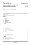
WinDriver Architecture
Figure 1.1: WinDriver Architecture
For hardware access, your application calls one of the WinDriver functions from the
WinDriver user-mode library (windrvr.h). The user-mode library calls the WinDriver
kernel, which accesses the hardware for you through the native calls of the operating
system.
WinDriver’s design minimizes performance hits on your code, even though it is
running in user mode. However, some hardware drivers have high performance
requirements that cannot be achieved in user mode. This is where WinDriver’s edge
sharpens. After easily creating and debugging your code in user mode, you may
drop the performance-critical modules of your code (such as a hardware interrupt
handler) into the WinDriver Kernel PlugIn without changing them at all. Now,
WinDriver kernel calls this module from kernel mode, thereby achieving maximal
performance. This allows you to program and debug in user mode, and still achieve
kernel performance where needed. In Windows CE and VxWorks there is no
separation between user mode and kernel mode; therefore, you may achieve optimal
performance directly from user mode, without needing to use the Kernel PlugIn in
these operating systems.
1 WinDriver Overview
26
1.7
What Platforms Does WinDriver Support?
WinDriver supports Windows 98/Me/NT/2000/XP/CE/CE.NET/Server 2003, Linux,
Solaris and VxWorks. The same source code will run on all supported platforms. The
executable you create will operate on Windows 98/Me/NT/2000/XP/Server 2003.
Even if your code is meant only for one of these operating systems, using WinDriver
will give you the flexibility to move your driver to another operating system without
needing to change your code.
1.8
Limitations of the Different Evaluation Versions
All the evaluation versions of WinDriver are full featured. No functions are limited or
crippled in any way. The evaluation version of WinDriver varies from the registered
version in the following ways:
• Each time WinDriver is activated, an Un-registered message appears.
• When using the DriverWizard, a dialog box with a message stating that an
evaluation version is being run appears on every interaction with the hardware.
• In the Linux, Solaris, VxWorks and CE versions, the driver will remain
operational for 60 minutes, after which time it must be restarted.
• The Windows evaluation version expires 30 days from the date of installation.
For more details please refer to appendix C.
1.9
1.9.1
How Do I Develop My Driver with WinDriver?
On Windows 98/Me/NT/2000/XP/Server 2003, Linux and
Solaris
1. Start DriverWizard. Refer to Chapter 5 for details.
2. Diagnose your device using DriverWizard.
3. Let DriverWizard generate skeletal code for your driver.
WinDriver v6.20 User’s Guide
27
4. Modify the code generated by DriverWizard to suit your application’s needs.
5. Run and debug your driver in user mode.
6. If your code contains performance-critical sections, improve their performance.
See Chapter 10 for details.
NOTE:
The code generated by DriverWizard is in fact a diagnostics program that contains
functions that read and write to any resource detected or defined (including
custom-defined registers), enables your card’s interrupts, listens to them, access
USB pipes and more.
1.9.2
On Windows CE
1. Plug your hardware into a Windows host machine.
2. Activate Visual C++ for CE on the host machine.
3. Diagnose your hardware using DriverWizard.
4. Let DriverWizard generate your driver’s skeletal code.
5. Modify this code using Visual C++ to meet your specific needs.
6. Test and debug your code and hardware from the CE emulation running on the
host machine.
7. If your code contains performance-critical sections, improve their performance.
See Chapter 10 for details.
NOTE:
ISAPnP is not supported under Windows CE.
TIP
If you cannot plug your hardware into your NT machine, you may still use
DriverWizard by manually entering all your resources into it. Let DriverWizard
generate your code and then test it on your hardware using a serial connection. After
verifying that the generated code works properly, modify it to meet your specific
needs. You may also use (or combine) any of the sample files for your driver’s
skeletal code.
1 WinDriver Overview
28
1.9.3
On VxWorks
1. Plug your hardware into a Windows host machine.
2. Diagnose your hardware using DriverWizard for Windows. Refer to Chapter 5
for details.
3. Let DriverWizard generate your driver’s skeletal code and project makefile for
Tornado.
4. Move the code to your tornado environment and compile it.
5. Modify this code using tornado development environment, or any other 32-bit
development environment, to meet your specific needs.
1.10
What Does the WinDriver Toolkit Include?
• A printed version of this manual
• Two months of free technical support (Phone/Fax/Email)
• WinDriver modules
• The WinDriver CD
– Utilities
– Chipset support APIs
– Sample files
1.10.1
WinDriver Modules
• WinDriver (WinDriver\include) – the general purpose hardware access toolkit.
The main files here are:
– windrvr.h: the WinDriver API, data structures and constants are defined
in this header file.
– wdu_lib.h: contains definitions of the USB user-mode logic interface.
– windrvr_int_thread.h: contains definitions of interrupt wrapper
functions to simplify interrupt handling.
WinDriver v6.20 User’s Guide
29
– windrvr_events.h: contains functions to implement event handling and
PnP notifications.
– wdlib.h: contains API definitions of the USB HID extended support.
– utils.h: OS specific implementation of threads and events.
– status_strings.h: error strings conversion from numerical return value.
• DriverWizard (Start Menu | Programs | WinDriver | DriverWizard) – a
graphical tool that diagnoses your hardware and enables you to easily generate
code for your driver (refer to Chapter 5 for details).
• Graphical Debugger (Start Menu | Programs | WinDriver | Debug
Monitor) – a graphical debugging tool that collects information about your
driver as it runs; on Linux, Solaris, WinCE and VxWorks you can use the
console version of this program (refer to Chapter 7 for details).
• WinDriver distribution package (WinDriver\redist) – the files you include in
the driver distribution to customers.
• WinDriver Kernel PlugIn (WinDriver\kerplug) – the files and samples needed
to create a Kernel PlugIn for WinDriver.
• This manual (Start Menu | Programs | WinDriver) – the full WinDriver
manual (this document) in PDF, Windows Help and HTML formats.
1.10.2
Utilities
• PCI_SCAN.EXE (\WinDriver\util\pci_scan.exe) – used to obtain a list of the
PCI cards installed and the resources allocated for each of them.
• PCI_DUMP.EXE (\WinDriver\util\pci_dump.exe) – used to obtain a dump
of all the PCI configuration registers of the PCI cards installed.
• USB_DIAG.EXE (\WinDriver\util\usb_diag.exe) – provides a list of the USB
devices installed and identifies the resources allocated for each one of them and
the resources used to access them.
The CE version includes:
• \REDIST\... \X86EMU\WINDRVR_CE_EMU.DLL: DLL that
communicates with the WinDriver kernel—for the x86 HPC emulation mode
of Windows CE.
1 WinDriver Overview
30
• \REDIST\... \X86EMU\WINDRVR_CE_EMU.LIB: an import library that
is used to link with WinDriver applications that are compiled for the x86 HPC
emulation mode of Windows CE.
1.10.3
WinDriver’s Specific Chipset Support
These are APIs that support the major PCI bridge chipsets and USB Controllers, for
even faster code development. Among others enhanced support is included for:
• WinDriver PLX APIs (for the 9030, 9050, 9052, 9054, 9060, 9080, 9056 and
9656 PCI bridges) – under the respective directory, e.g., WinDriver\plx\9050.
• WinDriver Marvell APIs (for the Marvell GT64 PCI bridges) –
WinDriver\marvell\gt64.
• WinDriver AMCC APIs (for the AMCC S5933 PCI bridges) –
WinDriver\amcc.
• WinDriver ALTERA (for Altera PCI cores) – WinDriver\altera.
• WinDriver QuickLogic APIs (for the QuickLogic PCI bridges) –
WinDriver\QuickLogic.
• WinDriver Cypress APIs (for the Cypress EZ-USB controllers) –
WinDriver\cypress.
• WinDriver STMicroelectronics APIs (for the ST7 and ST9 chips) –
WinDriver\st.
• WinDriver Texas Instruments APIs (for the TUSB3410, TUSB3210,
TUSB2136, TUSB5052 chips) – WinDriver\ti.
Each of the directories above includes the following subdirectories:
• \lib – the special chipset API for the enhanced support chip, written using the
WinDriver API.
• \xxx_diag - a sample diagnostics application, which was written using the
special library functions available for the chipsets; This application can be
compiled and executed as-is (xxx_diag i.e., p9054_diag.c for the PLX 9054
chip).
Refer to Chapter 8 for details.
WinDriver v6.20 User’s Guide
1.10.4
31
Samples
Here you will find the source code for the utilities listed earlier, along with other
samples that demonstrate how to perform the various driver tasks. Find the sample
closest to the driver you need and use it to jump-start your driver development process:
• WinDriver samples (WinDriver\samples) – samples that demonstrate different
common drivers.
• WinDriver
for PLX/Altera/Marvell/AMCC/QuickLogic/Cypress/STMicroelectronics/TI
samples
(e.g., WinDriver\PLX\p9054_diag or WinDriver\Cypress\bulk_sample etc.)
– source code of the diagnostics applications for the specific chipsets that
WinDriver supports.
1.11
Can I Distribute the Driver Created with
WinDriver?
Yes. WinDriver is purchased as a development toolkit, and any device driver created
using WinDriver may be distributed royalty free in as many copies as you wish. See
the license agreement (WinDriver\docs\license.txt) for more details.
1.12
Identifying the Right Tool for Your Development
Jungo offers two driver development products: WinDriver and KernelDriver.
WinDriver is designed for monolithic type user-mode drivers. It enables you to
access your hardware directly from within your user-mode application, without
writing a kernel-mode device driver. Using WinDriver you can either access
your hardware directly from your application (in user mode) or write a DLL
that you can call from many different applications.
In addition, WinDriver provides a complete solution for high-performance
drivers. Using WinDriver’s Kernel PlugIn, you can drop your user-mode code
into the kernel and reach full kernel-mode performance.
32
1 WinDriver Overview
A driver created with WinDriver runs on Windows 98/Me/NT/2000/XP/Server
2003, Linux, Solaris, VxWorks and Windows CE/CE.NET. Typically, a
developer without any previous driver knowledge can get a driver running in a
matter of a few hours (compared to several weeks with a kernel-mode driver).
KernelDriver is intended for creating standard operating system internal drivers
that require hardware access and that must communicate with the operating
system or must be implemented in the kernel.
A driver created with KernelDriver can run on Windows
98/Me/NT/2000/XP/Server 2003. KernelDriver dramatically simplifies the
difficult task of creating kernel-mode device drivers, by providing a hardware
access API in the kernel mode, which is portable across the supported operating
systems.
Chapter 2
Understanding Device Drivers
This chapter provides you with a general introduction to device drivers and takes
you through the structural elements of a device driver.
2.1
Device Driver Overview
Device drivers are the software segments that provides an interface between the
operating system and the specific hardware devices such as terminals, disks, tape
drives, video cards and network media. The device driver brings the device into and
out of service, sets hardware parameters in the device, transmits data from the kernel
to the device, receives data from the device and passes it back to the kernel, and
handles device errors.
A driver acts like a translator between the device and programs that use the device.
Each device has its own set of specialized commands that only its driver knows. In
contrast, most programs access devices by using generic commands. The driver,
therefore, accepts generic commands from a program and then translates them into
specialized commands for the device.
33
2 Understanding Device Drivers
34
2.2
Classification of Drivers According to
Functionality
There are numerous driver types, differing in their functionality. This subsection
briefly describes three of the most common driver types.
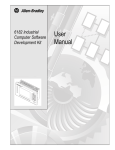
2.2.1
Monolithic Drivers
Monolithic drivers are device drivers that embody all the functionality needed to
support a hardware device. A monolithic driver is accessed by one or more user
applications, and directly drives a hardware device. The driver communicates with
the application through I/O control commands (IOCTLs) and drives the hardware
using calls to the different DDK, ETK, DDI/DKI functions.
Figure 2.1: Monolithic Drivers
Monolithic drivers are supported in all operating systems including all Windows
platforms and all Unix platforms.
WinDriver v6.20 User’s Guide
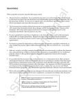
2.2.2
35
Layered Drivers
Layered drivers are device drivers that are part of a stack of device drivers that
together process an I/O request. An example of a layered driver is a driver that
intercepts calls to the disk and encrypts/decrypts all data being transferred to/from the
disk. In this example, a driver would be hooked on to the top of the existing driver
and would only do the encryption/decryption.
Layered drivers are sometimes also known as filter drivers, and are supported in all
operating systems including all Windows platforms and all Unix platforms.
Figure 2.2: Layered Drivers
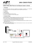
2.2.3
Miniport Drivers
A Miniport driver is an add-on to a class driver that supports miniport drivers. It is
used so the miniport driver does not have to implement all of the functions required
of a driver for that class. The class driver provides the basic class functionality for the
miniport driver.
A class driver is a driver that supports a group of devices of common functionality,
such as all HID devices or all network devices.
Miniport drivers are also called miniclass drivers or minidrivers, and are supported in
the Windows NT (or 2000) family, namely Windows NT/2000/XP and Server 2003.
Windows NT/2000/XP/Server 2003 provide several driver classes (called ports) that
2 Understanding Device Drivers
36
Figure 2.3: Miniport Drivers
handle the common functionality of their class. It is then up to the user to add only
the functionality that has to do with the inner workings of the specific hardware.
The NDIS miniport driver is one example of such a driver. The NDIS miniport
framework is used to create network drivers that hook up to NT’s communication
stacks, and are therefore accessible to common communication calls used by
applications. The Windows NT kernel provides drivers for the various communication
stacks and other code that is common to communication cards. Due to the NDIS
framework, the network card developer does not have to write all of this code, only
the code that is specific to the network card he is developing.
2.3
2.3.1
Classification of Drivers According to Operating
Systems
WDM Drivers
WDM (Windows Driver Model) drivers are kernel-mode drivers within the Windows
NT and Windows 98 operating system families. Windows NT family includes
Windows NT/2000/XP/Server 2003, and Windows 98 family includes Windows 98
and Windows Me.
WDM works by channeling some of the work of the device driver into portions of the
code that are integrated into the operating system. These portions of code handle all
WinDriver v6.20 User’s Guide
37
of the low-level buffer management, including DMA and Plug and Play (Pnp) device
enumeration.
WDM drivers are PnP drivers that support power management protocols, and include
monolithic drivers, layered drivers and miniport drivers.
2.3.2
VxD Drivers
VxD drivers are Windows 95/98/Me Virtual Device Drivers, often called VxDs
because the filenames end with the .vxd extension. VxD drivers are typically
monolithic in nature. They provide direct access to hardware and privileged operating
system functions. VxD drivers can be stacked or layered in any fashion, but the driver
structure itself does not impose any layering.
2.3.3
Unix Device Drivers
In the classic Unix driver model, devices belong to one of three categories: character
(char) devices, block devices and network devices. Drivers that implement these
devices are correspondingly known as char drivers, block drivers or network drivers.
Under Unix, drivers are code units linked into the kernel that run in privileged kernel
mode. Generally, driver code runs on behalf of a user-mode application. Access to
Unix drivers from user-mode applications is provided via the file system. In other
words, devices appear to the applications as special device files that can be opened.
Unix device drivers are either layered or monolithic drivers. A monolithic driver can
be perceived as a one-layer layered driver.
2.3.4
Linux Device Drivers
Linux device drivers are based on the classic Unix device driver model. In addition,
Linux introduces some new characteristics.
Under Linux, a block device can be accessed like a character device, as in Unix, but
also has a block-oriented interface that is invisible to the user or application.
Traditionally, under Unix, device drivers are linked with the kernel, and the system is
brought down and restarted after installing a new driver. Linux introduces the concept
of a dynamically loadable driver called a module. Linux modules can be loaded or
removed dynamically without requiring the system to be shut down. A Linux driver
can be written so that it is statically linked or written in a modular form that allows
2 Understanding Device Drivers
38
it to be dynamically loaded. This makes Linux memory usage very efficient because
modules can be written to probe for their own hardware and unload themselves if they
cannot find the hardware they are looking for.
Like Unix device drivers, Linux device drivers are either layered or monolithic
drivers.
2.3.5
Solaris Device Drivers
Solaris device drivers are also based on the classic Unix device driver model. Like
Linux drivers, Solaris drivers may be either statically linked with the kernel or
dynamically loaded and removed from the kernel.
Like Unix and Linux device drivers, Solaris device drivers are either layered or
monolithic drivers.
2.4
The Entry Point of the Driver
Every device driver must have one main entry point, like the main() function in a
C console application. This entry point is called DriverEntry() in Windows and
init_module() in Linux. When the operating system loads the device driver, this
driver entry procedure is called.
There is some global initialization that every driver needs to perform only once when
it is loaded for the first time. This global initialization is the responsibility of the
DriverEntry()/init_module() routine. The entry function also registers
which driver callbacks will be called by the operating system. These driver callbacks
are operating system requests for services from the driver. In Windows, these
callbacks are called dispatch routines, and in Linux they are called file operations.
Each registered callback is called by the operating system as a result of some criteria,
such as disconnection of hardware, for example.
2.5
Associating the Hardware to the Driver
Operating systems differ in how they link a device to its driver.
In Windows, the link is performed by the INF file, which registers the device to work
with the driver. This association is performed before the DriverEntry() routine
is called. The operating system recognizes the device, looks up in its database which
WinDriver v6.20 User’s Guide
39
INF file is associated with the device, and according to the INF file, calls the driver’s
entry point.
In Linux, the link between a device and its driver is defined in the init_module()
routine. The init_module() routine includes a callback which states what
hardware the driver is designated to handle. The operating system calls the driver’s
entry point, based on the definition in the code.
2.6
Communicating with Drivers
A driver can create an instance, thus enabling an application to open a handle to the
driver through which the application can communicate with it.
The applications communicate with the drivers using a file access API (Application
Program Interface). Applications open a handle to the driver using CreateFile()
call (in Windows), or open() call (in Linux) with the name of the device as
the file name. In order to read from and write to the device, the application calls
ReadFile() and WriteFile() (in Windows), or read(), write() in Linux.
Sending requests is accomplished using an I/O control call, called
DeviceIoControl() (in Windows), and ioctl() in Linux. In this I/O
control call, the application specifies:
• The device to which the call is made (by providing the device’s handle).
• An IOCTL code that describes which function this device should perform.
• A buffer with the data on which the request should be performed.
The IOCTL code is a number that the driver and the requester agree upon for a
common task.
The data passed between the driver and the application is encapsulated into a structure.
In Windows, this structure is called an I/O Request Packet (IRP), and is encapsulated
by the I/O Manager. This structure is passed on to the device driver, which may
modify it and pass it down to other device drivers.
Chapter 3
WinDriver USB Overview
This chapter explores the basic characteristics of the USB bus and introduces
WinDriver USB’s features and architecture.
3.1
Introduction to USB
USB (Universal Serial Bus) is an industry standard extension to the PC architecture
for attaching peripherals to the computer. The Universal Serial Bus was originally
developed in 1995 by leading PC and telecommunication industry companies, such
as Intel, Compaq, Microsoft and NEC. USB was developed to meet several needs.
Among them were the needs for an inexpensive and widespread connectivity solution
for peripherals in general and for computer telephony integration in particular, an
easy-to-use and flexible method of reconfiguring the PC, and a solution for adding a
large number of external peripherals.
The USB interface meets these needs. A single USB port can be used to connect
up to 127 peripheral devices. USB also supports Plug and Play installation and hot
swapping. USB 1.1 supports both isochronous and asynchronous data transfers and
has dual speed data transfer: 1.5 Mbps (megabits per second) for low-speed USB
devices and 12 Mbps for high-speed USB devices (much faster than the original serial
port). Cables connecting the device to the PC can be up to five meters (16.4 feet)
long. USB includes built-in power distribution for low power devices and can provide
limited power (up to 500 mA of current) to devices attached on the bus.
Because of these benefits, USB is enjoying broad market acceptance today.
40
WinDriver v6.20 User’s Guide
41
USB 2.0 supports a signalling rate of 480 Mbps, 40 times faster than USB 1.1. USB
2.0 is fully forward- and backward-compatible with USB 1.1 and uses existing cables
and connectors.
USB 2.0 supports connections with PC peripherals that provide expanded
functionality and require wider bandwidth. In addition, it can handle a larger
number of peripherals simultaneously.
USB 2.0 enhances the user’s experience of many applications, including interactive
gaming, broadband Internet access, desktop and Web publishing, Internet services
and conferencing.
3.2
WinDriver USB Benefits
• External connection, maximizing ease of use
• Self identifying peripherals supporting automatic mapping of function to driver
and configuration
• Dynamically attachable and re-configurable peripherals
• Suitable for device bandwidths ranging from a few Kbps to hundreds of Mbps
• Supports isochronous as well as asynchronous transfer types over the same set
of wires
• Supports simultaneous operation of many devices (multiple connections)
• Supports USB 2.0 (Hi-Speed) devices for the operating systems that officially
support this specification
• Guaranteed bandwidth and low latencies; appropriate for telephony, audio, etc.
(isochronous transfer may use almost entire bus bandwidth)
• Flexibility: supports a wide range of packet sizes and a wide range of data rates
• Robustness: built-in error handling mechanism and dynamic insertion and
removal of devices with no delay observed by the user
• Synergy with PC industry
• Optimized for integration in peripheral and host hardware
3 WinDriver USB Overview
42
• Low-cost implementation, therefore suitable for development of low-cost
peripherals
• Low-cost cables and connectors
• Uses commodity technologies
• Built-in power management and distribution
• Specific library support for custom USB HID devices
3.3
USB Components
USB Host: The USB host computer is where the USB host controller is installed
and where the client software/device driver runs. The USB host controller is
the interface between the host and the USB peripherals. The host is responsible
for detecting the attachment and removal of USB devices, managing the control
and data flow between the host and the devices, providing power to attached
devices and more.
USB Hub: A USB device that allows multiple USB devices to attach to a single
USB port on a USB host. Hubs on the back plane of the hosts are called root
hubs. Other hubs are called external hubs.
USB Function: A USB device that can transmit or receive data or control
information over the bus and that provides a function. Compound devices
provide multiple functions on the USB bus.
3.4
Data Flow in USB Devices
During the operation of a USB device, data flows between the client software and
the device. The data is transferred via pipes that run between memory buffers of the
software on the host and endpoints on the device.
A uniquely identifiable entity on a USB device, an endpoint is the source or terminus
of the data that flows from or to the device. Each USB device, logical or physical,
has a collection of independent endpoints. Each endpoint has the following attributes:
bus access frequency, bandwidth requirement, endpoint number, error handling
mechanism, maximum packet size that can be transmitted or received, transfer type
and direction (into or out of the device).
WinDriver v6.20 User’s Guide
43
A pipe is a logical component that represents an association between an endpoint on
the USB device and software on the host. Data is moved to and from a device through
a pipe. A pipe can be either a stream pipe or a message pipe, depending on the type
of data transfer used in the pipe. Stream pipes handle interrupt, bulk and isochronous
transfers, while message pipes support the control transfer type. The different USB
transfer types are discussed below:
Figure 3.1: USB Endpoints
3.5
USB Data Exchange
The USB standard supports two kinds of data exchange between a host and a device:
functional data exchange and control exchange.
Functional data exchange is used to move data to and from the device. There are
44
3 WinDriver USB Overview
three types of data transfers: bulk transfers, interrupt transfers and isochronous
transfers.
Control exchange is used to configure a device when it is first attached and can also
be used for other device-specific purposes, including control of other pipes on
the device. Control exchange takes place via a control pipe, mainly the default
Pipe 0, which always exists. The control transfer consists of a setup stage (in
which a setup packet is sent from the host to the device), an optional data stage
and a status stage.
More information on how to implement the control transfer by sending setup packets
can be found in Chapter 9, which deals with WinDriver implementation issues.
The screen shot below depicts a USB device with one bidirectional control and three
functional data transfer pipes/endpoints:
Figure 3.2: USB Pipes
WinDriver v6.20 User’s Guide
3.6
45
USB Data Transfer Types
The USB device (function) communicates with the host by transferring data through
a pipe between a memory buffer on the host and an endpoint on the device. USB
provides for four different transfer types. A type is selected for a specific endpoint
according to the requirements of the device and the software. The transfer type of a
specific endpoint is determined in the endpoint descriptor.
Data transfer types provided for by the USB specification are as follows:
Control Transfer is mainly intended to support configuration, command and status
operations between the software on the host and the device. Each USB
device has at least one control pipe (default pipe), which provides access to the
configuration, status and control information. The control pipe is a bidirectional
pipe. Control transfer is bursty, non-periodic communication. Control transfer
has a robust error detection, recovery and retransmission mechanism and retries
are made without the involvement of the driver. Control transfer is used by
low-speed and high-speed devices.
Isochronous Transfer is most commonly used for time-dependent information,
such as multimedia streams and telephony. The transfer is periodic and
continuous. The isochronous pipe is unidirectional and a certain endpoint
can either transmit or receive information. Bidirectional isochronous
communication requires two isochronous pipes, one in each direction. USB
guarantees the isochronous transfer access to the USB bandwidth (that is it
reserves the required amount of bytes of the USB frame) with bounded latency
and guarantees the data transfer rate through the pipe unless there is less
data transmitted. Up to 90% of the USB frame can be allocated to periodic
transfers (isochronous and interrupt transfers). If, during configuration, there
is not sufficient bus time available for the requester isochronous pipe, the
configuration is not established. Since timeliness is more important than
correctness in these types of transfers, no retries are made in case of error in the
data transfer. However, the data receiver can determine that an error occurred
on the bus. Isochronous transfer can be used only by high-speed devices.
Interrupt Transfer is intended for devices that send and receive small amounts of
data infrequently or in an asynchronous time frame. An interrupt transfer type
guarantees a maximum service period and a that delivery will be re-attempted
in the next period if there is an error on the bus. The interrupt pipe, like the
isochronous pipe, is unidirectional. The bus access time period (1-255 ms for
high-speed devices and 10-255 ms for low-speed devices) is specified by the
3 WinDriver USB Overview
46
endpoint of the interrupt pipe. Although the host and the device can only count
on the time period specified by the endpoint, the system can provide a shorter
period (up to 1 ms).
Bulk Transfer is non-periodic, large packet, bursty communication. Bulk transfer
typically supports devices that transfer large amounts of non-time sensitive
data, and that can use any available bandwidth, such as printers and scanners.
Bulk transfer allows access to the bus on an "as-available" basis, guarantees
the data transfer but not the latency, and provides an error check mechanism
with retries attempts. If part of the USB bandwidth is not being used for other
transfers, the system will use it for bulk transfer. Like the other stream pipes
(isochronous and interrupt), the bulk pipe is also unidirectional. Bulk transfer
can only be used by high-speed devices.
3.7
USB Configuration
Before the USB function (or functions, in a compound device) can be operated,
the device must be configured. The host does the configuring by acquiring the
configuration information from the USB device. USB devices report their attributes
by descriptors. A descriptor is the defined structure and format in which the data is
transferred. A complete description of the USB descriptors can be found in Chapter 9
of the USB Specification (see http://www.usb.org for the full specification).
It is best to view the USB descriptors as a hierarchical structure with four levels:
• The Device level
• The Configuration level
• The Interface level (this level may include an optional sub-level called alternate
settings)
• The Endpoint level
There is only one device descriptor for each USB device. Each device has one or more
configurations, each configuration has one or more interfaces, and each interface has
zero or more endpoints.
Device Level: The device descriptor includes general information about the USB
device, that is, global information for all of the device configurations. The
WinDriver v6.20 User’s Guide
47
device descriptor identifies, among other things, the device class (HID device,
hub, locator device, etc.), subclass, protocol code, vendor ID, device ID and
more. Each USB device has one device descriptor.
Configuration Level: A USB device has one or more configuration descriptors.
Each descriptor identifies the number of interfaces grouped in the configuration
and the power attributes of the configuration (such as self-powered, remote
wakeup, maximum power consumption and more). Only one configuration
can be loaded at a given time. For example, an ISDN adapter might have two
different configurations, one that presents it with a single interface of 128 Kbps
and a second that presents it with two interfaces of 64 Kbps each.
Interface Level: The interface is a related set of endpoints that present a specific
functionality or feature of the device. Each interface may operate independently.
The interface descriptor describes the number of the interface, the number of
endpoints used by this interface and the interface-specific class, subclass and
protocol values when the interface operates independently. In addition, an
interface may have alternate settings. The alternate settings allow the endpoints
or their characteristics to be varied after the device is configured.
Endpoint Level: The lowest level is the endpoint descriptor that provides the
host with information regarding the data transfer type of the endpoint and
the bandwidth of each endpoint (the maximum packet size of the specific
endpoint). For isochronous endpoints, this value is used to reserve the bus time
required for the data transfer. Other attributes of the endpoints are their bus
access frequency, their endpoint number, their error handling mechanism and
their direction.
Seems complicated? Not at all! WinDriver automates the USB configuration process.
The included DriverWizard and USB diagnostics application scan the USB bus,
detect all USB devices and their configurations, interfaces, settings and endpoints,
and enable the developer to pick the desired configuration before starting driver
development.
WinDriver identifies the endpoint transfer type as determined in the endpoint
descriptor. The driver created with WinDriver contains all configuration information
acquired at this early stage.
3 WinDriver USB Overview
48
3.8
WinDriver USB
WinDriver USB enables developers to quickly develop high-performance drivers
for USB-based devices, without having to learn the USB specifications or the OS
internals. Using WinDriver USB, developers can create USB drivers without having
to use the DDK, and without having to be familiar with Microsoft’s WDM (Win32
Driver Module).
The driver code developed with WinDriver USB is binary compatible with Windows
98, Windows Me, Windows 2000, Windows XP and Windows Server 2003.
The source code will be code compatible with all other operating systems supported
by WinDriver USB, including Linux and Windows CE. For an up-to-date list of
operating systems supported by WinDriver USB, please visit Jungo’s web site at:
http://www.jungo.com.
WinDriver USB encapsulates the USB specification and architecture, letting you
focus on your application logic. WinDriver USB features DriverWizard, with which
you can detect your hardware, configure it and test it before writing a single line of
code. DriverWizard first leads you through the configuration procedure, where you
can choose the desired configuration, interface and alternate setting through a friendly
graphical user interface. After detecting and configuring your USB device, you can
then test it, listen to pipes, write and read packets and ensure that all your hardware
resources function as expected. WinDriver USB is a generic tool kit that supports all
USB devices from all vendors and with all types of configurations.
After your hardware is diagnosed, DriverWizard automatically generates your device
driver source code in C, Delphi or Visual Basic. WinDriver USB provides user-mode
APIs to your hardware, which you can call from within your application. The
WinDriver USB API is specific to your USB device and includes USB-unique
operations such as reset-pipe and reset-device. Along with the device API, WinDriver
USB creates a diagnostics application, which just needs to be compiled and run. You
can use this application as your skeletal driver to jump-start your development cycle.
If you are a VB or a Delphi programmer, you will find that the WinDriver USB API
is also supported in VB and Delphi, giving you everything you need to develop your
driver in VB and Delphi.
DriverWizard also automates the creation of an INF file, if needed. An INF file is a
text file used by the Plug and Play mechanisms of Windows 98/Me/2000/XP/Server
2003 to load the driver for a newly installed piece of hardware or to replace an
existing driver. The INF file includes all necessary information about the device(s)
and the files to be installed. INF files are required for pieces of hardware that identify
themselves, such as USB and PCI. In some cases, the INF file of your specific device
WinDriver v6.20 User’s Guide
49
is included in the INF files that are shipped with the operating system. In other cases,
you will need to create an INF file for your device. WinDriver automates this process
for you. More information on how to create your own INF file with DriverWizard can
be found in Chapter 5, which explains the DriverWizard. Instructions for installing
INF files can be found in Chapter 14, which illustrates how to distribute your driver.
With WinDriver USB, all development is done in user mode, using familiar
development and debugging tools and your favorite compiler (such as MSDEV,
Visual C/C++, Borland Delphi, Borland C++ or Visual Basic).
3 WinDriver USB Overview
50
3.9
WinDriver USB Architecture
Figure 3.3: WinDriver USB Architecture
To access your hardware, your application makes calls to the WinDriver kernel module
using functions from the WinDriver USB API. . The high-level functions make use
of the low-level functions, which use IOCTLs to enable communication between the
WinDriver kernel module and your user-mode application. The WinDriver kernel
module accesses your USB device resources through the native operating system
calls.
There are two layers responsible for abstracting the USB device to the USB device
driver. The upper one is the USB Driver layer (including the USB Driver (USBD)
WinDriver v6.20 User’s Guide
51
and USB Hub Driver) and the lower one is the Host Controller Driver layer (HCD).
The division of duties between the HCD and USBD is not defined, and is operating
system dependent. Both HCD and USBD are software interfaces and components of
the operating system, where the HCD layer represents a lower level of abstraction.
The HCD is the software layer that provides an abstraction of the host controller
hardware while the USBD provides an abstraction of the USB device and the data
transfer between the host software and the function of the USB device.
The USBD communicates with its clients (the specific device driver for example)
through the USB Driver Interface. At the lower level, the USBD and USB Hub Driver
implement the hardware access and data transfer by communicating with the HCD
using the host controller driver interface.
The USB Hub Driver is responsible for identifying the addition and removal of
devices from a particular hub. Once the Hub Driver receives a signal that a device was
attached or detached, it uses additional host software and the USB driver to recognize
and configure the device. The software implementing the configuration can include
the hub driver, the device driver and other software.
WinDriver USB abstracts the configuration procedure and hardware access
described above for the developer. With WinDriver USB API, developers can
do all the hardware-related operations without having to master the lower levels of
implementing these activities.
3.10
Which Drivers Can I Write with WinDriver
USB?
Almost all monolithic drivers (drivers that need to access specific USB devices) can
be written with WinDriver USB. In cases where a standard driver needs to be written,
e.g., NDIS driver, SCSI driver, Display driver, USB to Serial port drivers, USB
layered drivers, etc., use KernelDriver USB (also from Jungo).
For quicker development time, select WinDriver USB over KernelDriver USB
wherever possible.
3 WinDriver USB Overview
52
3.11
WinDriver Extension for Custom USB HID
Devices
WinDriver has a new feature to support the development of drivers for custom USB
HID devices. This extension provides user level libraries and DLLs that enable the
application developer to access his custom USB HID device without needing to write
device drivers at all. The WinDriver extension for custom USB HID devices uses
the standard USB HID class drivers that are part of the operating system, providing
developers with an easy-to-use API and significantly shortening the amount of
time needed to develop support for custom HID USB devices. Because WinDriver
extension for custom USB HID devices exploits the standard HID support provided
with the operating system, no kernel-level driver need be developed, resulting in
hassle free distribution and maintenance of your application.
There are several differences between WinDriver extension for custom USB HID
devices and classic WinDriver:
• User-mode DLL vs. kernel-mode driver
• Different API (WDL_ vs. WD_)
• Usage of HID class driver vs. usage of custom WinDriver USB driver
• Distribution issues (wdlib.dll vs. windrvr6.sys)
The WinDriver extension for custom USB HID devices uses a user-level DLL to
provide support for HID. Throughout this manual, certain sections may differ
between classic WinDriver and the WinDriver extension for custom USB HID
devices. If you are developing using the WinDriver extension for custom USB HID
devices, be sure to refer to the sections directed at that product.
Chapter 4
Installing WinDriver
This chapter takes you through the WinDriver installation process, and shows you
how to verify that your WinDriver is properly installed. The last section discusses
the uninstall procedure.
4.1
4.1.1
System Requirements
For Windows 98/Me
• An x86 processor
• Any 32-bit development environment supporting C, VB or Delphi
4.1.2
For Windows NT/2000/XP/Server 2003
• An x86 processor
• Any 32-bit development environment supporting C, VB or Delphi
• Windows NT: Service Pack 3 or higher (Service Pack 6 is recommended)
53
4 Installing WinDriver
54
4.1.3
For Windows CE
• An x86 Windows CE target platform
or
A MIPS / ARM Windows CE target platform. This option is available for
Windows CE 4.x (.NET)
• Windows NT/2000/XP/Server 2003 host development platform
• Microsoft eMbedded Visual C++ with a corresponding target SDK
or
Microsoft Platform Builder with corresponding BSP (Board Support Package)
for the target platform
4.1.4
For Linux
• Linux 2.2, 2.4 or 2.6
• An x86 processor
• A GCC compiler for WinDriver installation and for Kernel PlugIn
NOTE:
The GCC compiler must be the same version as the running kernel
• Any 32-bit development environment supporting C (such as GCC) for user
mode
4.1.5
For Solaris
• Solaris 8.0/9.0
• 64-bit or 32-bit kernel on SPARC platform
or
32-bit kernel on x86 platform
• Any development environment supporting C (such as GCC)
• WinDriver 5.22 is still provided for Solaris 2.6/7.0 32-bit kernel on Intel x86
platform.
WinDriver v6.20 User’s Guide
55
NOTE:
If you have chosen a development environment other than GCC, make
sure libgcc is installed on your computer. You may download it from
http://www.sunfreeware.com.
Set the LD_LIBRARY_PATH to the location of your libgcc, a probable location
would be:
LD_LIBRARY_PATH= /usr/local/lib:/usr/local/lib/sparcv9
4.1.6
For VxWorks
• VxWorks 5.4
• Windows host development platform
• Tornado 2.0 IDE
• Target Platform running a processor that has a BSP (Board Support Package)
compatible with the list of CPU/BSP combinations supported by DriverBuilder
For an up-to-date list see:
http://www.jungo.com/db- vxworks.html#platforms
For information on BSP compatibility, please contact your nearest WindRiver
Systems support representative.
4.2
WinDriver Installation Process
The WinDriver CD contains all versions of WinDriver for all the different
operating systems. The CD’s root directory contains the Windows 98/Me and
NT/2000/XP/Server 2003 version. This will automatically begin when you insert the
CD into your CD drive. The other versions of WinDriver are located in subdirectories,
i.e., \Linux, \Wince and so on.
4.2.1
WinDriver Installation Instructions for Windows 98, Me,
NT, 2000, XP and Server 2003
NOTE:
You must have administrative privileges in order to install WinDriver on Windows
98, Me, NT, 2000, XP and Server 2003.
4 Installing WinDriver
56
1. Insert the WinDriver CD into your CD-ROM drive.
(When installing WinDriver by downloading it from Jungo’s web site instead
of using the WinDriver CD, double click the downloaded WinDriver file
(WDxxx.EXE) in your download directory, and go to Step 3).
2. Wait a few seconds until the installation program starts automatically. If for
some reason it does not start automatically, double-click the file WDxxx.EXE
(where xxx is the version number) and click the Install WinDriver button.
3. Read the license agreement carefully, and click Yes if you accept its terms.
4. Choose the destination location in which to install WinDriver.
5. In the Setup Type screen, choose one of the following:
• Typical – to install all WinDriver modules (generic WinDriver toolkit +
specific chipset APIs)
• Compact – to install only the generic WinDriver toolkit
• Custom – to choose which modules of WinDriver to install; you may
choose which APIs will be installed
6. After the installer finishes copying the required files, choose whether to view
the quick-start guides.
7. You will be prompted to reboot your computer.
The following steps are for registered users only:
In order to register your copy of WinDriver with the license you received from Jungo,
follow the steps below:
1. Activate DriverWizard GUI (Start | Programs | WinDriver |
DriverWizard).
2. Select the Register WinDriver option from the File menu and insert the
license string you received from Jungo. Click the Activate License button.
3. To activate source code you developed during the evaluation period, please
refer to WD_License function reference in Section A.1.9.
WinDriver v6.20 User’s Guide
4.2.2
57
Installing WinDriver CE
Installing WinDriver CE when Building New CE-based Platforms
The following instructions apply to platform developers who build WinCE kernel
images using Windows CE Platform Builder:
NOTE:
We recommend that you read Microsoft’s documentation and understand the
Windows CE and device driver integration procedure before you perform the
installation.
1. Run Microsoft Platform Builder and open your platform.
2. Select Open Build Release Directory from the Build menu.
3. Copy the WinDriver CE kernel file
\WinDriver\redist\TARGET_CPU\windrvr6.dll
to the %_FLATRELEASEDIR% subdirectory on your development platform
(should be the current directory in the new command window).
4. Append the contents of the file
\WinDriver\samples\wince_install\PROJECT_WD.REG
to the file PROJECT.REG in the %_FLATRELEASEDIR% subdirectory.
NOTE:
On non-x86 platforms, for PCI only: make sure you copy the lines specified
for PCI from PROJECT_WD.REG to PROJECT.REG, after removing the
comment marks, and inserting the card specific information.
5. Append the contents of the file
\WinDriver\samples\wince_install\PROJECT_WD.BIB
to the file PROJECT.BIB in the %_FLATRELEASEDIR% subdirectory.
This step is only necessary if you want the WinDriver CE kernel file
(windrvr6.dll) to be a permanent part of the Windows CE image (NK.BIN).
This would be the case if you were transferring the file to your target platform
using a floppy disk. If you prefer to have the file windrvr6.dll loaded on
demand via the CESH/PPSH services, you need not carry out this step until
you build a permanent kernel.
6. Select Make Image from the Build menu and name the new image NK.BIN.
4 Installing WinDriver
58
7. Download your new kernel to the target platform and initialize it either by
selecting Download/Initialize from the Target menu or by using a floppy disk.
8. Restart your target CE platform. The WinDriver CE kernel will automatically
load.
9. Compile and run the sample programs to make sure that WinDriver CE is
loaded and is functioning correctly. (See Section 4.4, which describes how to
check your installation.)
Installing WinDriver CE when Developing Applications for CE Computers
The following instructions apply to driver developers who do not build the WinCE
kernel, but only download their drivers, built using Microsoft eMbedded Visual C++,
to a ready-made WinCE platform:
1. Insert the WinDriver CD into your Windows host CD drive.
2. Exit from the auto installation.
3. Double click the Cd_setup.exe file found in the \Wince directory on the CD.
This will copy all needed WinDriver files to your host development platform.
4. Copy the WinDriver CE kernel file
\WinDriver\redist\TARGET_CPU\windrvr6.dll
to the \WINDOWS subdirectory of your target CE computer.
5. Use the Windows CE Remote Registry Editor tool (ceregedt.exe) or the
Pocket Registry Editor (pregedt.exe) on your target CE computer to modify
your registry so that the WinDriver CE kernel is loaded appropriately. The
file \WinDriver\samples\wince_install\PROJECT_WD.REG contains the
appropriate changes to be made.
6. Restart your target CE computer. The WinDriver CE kernel will automatically
load. You will have to do a warm reset rather than just suspend/resume (use the
reset or power button on your target CE computer).
7. Compile and run the sample programs (see Section 4.4, which describes how
to check your installation) to make sure that WinDriver CE is loaded and is
functioning correctly.
WinDriver v6.20 User’s Guide
4.2.3
59
WinDriver Installation Instructions for Linux
Preparing the System for Installation
In Linux, kernel modules must be compiled with the same header files that the kernel
itself was compiled with. Since WinDriver installs the kernel module windrvr6.o, it
must compile with the header files of the Linux kernel during the installation process.
Therefore, before you install WinDriver for Linux, verify that the Linux source code
and the file versions.h are installed on your machine:
Install linux kernel source code
• If you have yet to install Linux, please choose Custom installation when
performing the installation and then choose to install the source code.
• If Linux is already installed on the machine, you must check to see if the Linux
source code was installed. You can do this by looking for linux in the /usr/src
directory. If the source code is not installed, you can either reinstall Linux
with the source code, as described above, or you can install the source code by
following these steps:
1. Login as super user.
2. Type:
/$ rpm -i /<source location>/ <Linux
distributor>/RPMS/kernel-source-<version number>
(For example: to install the source code from the Linux installation
CD-ROM, for RedHat 7.1, type:
/$ rpm -i /mnt/cdrom/RedHat/RPMS/
kernel-source-2.4.2.-2.i386rpm)
TIP
If you do not have an RPM with the source code, you may download it
from: http://rpmfind.net/linux/RPM/.
Install version.h
• The file version.h is created when you first compile the Linux kernel source
code. Some distributions provide a compiled kernel without the file version.h.
Look under /usr/src/linux/include/linux/ to see if you have this file. If you do
not, please follow these steps:
4 Installing WinDriver
60
1. Type:
/$ make xconfig
2. Save the configuration by choosing Save and Exit.
3. Type:
/$ make dep.
Before proceeding with the installation, you must also make sure that you have a
linux symbolic link. If you do not, please create one by typing:
/usr/src$ ln -s <target kernel>/ linux
(For example: for Linux 2.4 kernel type:
/usr/src$ ln -s linux-2.4/ linux)
Installation
1. Insert the WinDriver CD into your Linux machine CD drive or copy the
downloaded file to your preferred directory.
2. Change directory to your preferred installation directory (your home directory,
for example):
/$ cd ~
3. Extract the file WDxxxLN.tgz (where xxx is the version number):
~$ tar xvzf /<file location>/WDxxxLN.tgz
For example:
• From a CD:
~$ tar xvzf /mnt/cdrom/LINUX/WDxxxLN.tgz
• From a downloaded file:
~$ tar xvzf /home/username/WDxxxLN.tgz
4. Change directory to WinDriver (this directory is created by tar):
~$ cd WinDriver/
5. Install WinDriver:
(a) ~/WinDriver$ make
(b) Become super user:
~/WinDriver$ su
(c) Install the driver:
~/WinDriver# make install
WinDriver v6.20 User’s Guide
61
6. Create a symbolic link so that you can easily launch the DriverWizard GUI
~/WinDriver$ ln -s
<full path to WinDriver>/WinDriver/wizard/wdwizard/
usr/bin/wdwizard
7. Change the read and execute permissions on the file wdwizard so that ordinary
users can access this program.
8. Change the user and group ids and give read/write permissions to the device file
/dev/windrvr6 depending on how you wish to allow users to access hardware
through the device.
9. You can now start using WinDriver to access your hardware and generate your
driver code!
The following steps are for registered users only
In order to register your copy of WinDriver with the license you received from Jungo,
follow the steps below:
1. Activate the DriverWizard GUI:
~/WinDriver/wizard$ ./wdwizard
2. Select the Register WinDriver option from the File menu and insert the
license string you received from Jungo.
3. Click the Activate License button.
4. To register source code you developed during the evaluation period, please refer
to WD_License function reference [A.1.9].
Restricting Hardware Access on Linux
CAUTION:
Since /dev/windrvr6 gives direct hardware access to user programs, it may
compromise kernel stability on multi-user Linux systems. Please restrict access to
the DriverWizard and the device file /dev/windrvr6 to trusted users.
For security reasons the WinDriver installation script does not automatically perform
the steps of changing the permissions on /dev/windrvr6 and the DriverWizard
executable (wdwizard).
4 Installing WinDriver
62
4.2.4
WinDriver Installation Instructions for Solaris
Installation of WinDriver should be performed by the system administrator logged
in as root, or with root privileges, since the WinDriver installation process includes
installation of the kernel module windrvr6.
1. Insert your CD into your Solaris machine CD drive or copy the downloaded file
to your preferred directory.
2. Change directory to preferred installation directory (your home directory, for
example):
/$ cd ~
3. Copy the file WDxxxSLS.tgz to the current directory (here ‘xxx’ stands for the
version number—500, for example):
~$ cp /home/username /WDxxxSLS.tgz /
4. Extract the file:
~$ gunzip -c WDxxxSLS.tgz | tar xvf 5. Change directory to WinDriver.
6. Install WinDriver:
The installation requires you to determine on which PCI card you will be
working, by defining the device’s Vendor ID and Device ID (hexadecimal
values). There are two different ways to do this and install the driver:
• Modify the installation file before performing the installation and then
install WinDriver:
(a) Open the file install_windrvr for editing, and change the default
Vendor ID and default Device ID to your PCI card’s identification
values.
(b) Install WinDriver:
~/WinDriver# ./install_windrvr
• Use the Command Line to change your device’s identification values and
install the driver in one step, by typing:
~/WinDriver# VENDOR_ID=XXXX DEVICE_ID=XXXX
./install_windrvr
WinDriver v6.20 User’s Guide
63
NOTE:
From version 5.x and above this directory is created by tar, but in versions
preceding 5.x the WinDriver directory is not created by the extraction.
Therefore, when working with versions preceding 5.x (version 4.33, for
example) first create a directory (e.g., WinDriver) before proceeding with the
installation.
(/$ mkdir ~/WinDriver)
The following three steps are optional:
7. Create a symbolic link so that you can easily launch the DriverWizard GUI:
~/WinDriver# ln -s ~/WinDriver/wizard/wdwizard
/usr/bin/wdwizard
8. Change the read and execute permissions on the file wdwizard so that ordinary
users can access this program.
9. Change the user and group ids and give read/write permissions to the device file
/dev/windrvr6 depending on how you wish to allow users to access hardware
through the device.
10. You can now start using WinDriver to access your hardware and generate your
driver code!
The following steps are for registered users only:
In order to register your copy of WinDriver with the license you have received from
Jungo, please follow the steps below:
1. Activate the DriverWizard GUI:
~/WinDriver/wizard$ ./wdwizard
2. Select the Register WinDriver option from the File menu and insert the
license string you received from Jungo.
3. Click the Activate License button.
4. To register source code you developed during the evaluation period, please refer
to WD_License function reference [A.1.9].
4 Installing WinDriver
64
Restricting Hardware Access on Solaris
CAUTION:
Since /dev/windrvr6 gives direct hardware access to user programs, it may
compromise kernel stability on multi-user Solaris systems. Please restrict access to
DriverWizard and the device file /dev/windrvr6 to trusted users.
For security reasons the WinDriver installation script does not automatically perform
the steps of changing the permissions on /dev/windrvr6 and the DriverWizard
executable (wdwizard).
4.2.5
DriverBuilder Installation Instructions for VxWorks
The following describes the installation of DriverBuilder for VxWorks. DriverBuilder
development environment works with Tornado 2 for Windows only (on x86 platform).
Drivers generated using version 5.x and above of DriverBuilder will run on Intel x86
BSPs (pc486, pcPentium and pcPentiumPro), PPC 821/860 with MBX821/860 and
PPC 750 (IBM PPC 604) with MCP750. For an up-to-date list see:
http://www.jungo.com/db- vxworks.html#platforms.
Installation:
1. Download DriverBuilder for VxWorks.
2. Change drive to the preferred root drive for DriverBuilder. For example:
\> c:\
3. Unpack the file you downloaded:
\> unzip -d DBxxxVX.zip c:\ (Here ‘xxx’ stands for the version
number, e.g., 500.)
NOTE:
The extraction creates a directory called DriverBuilder and then places all of
the DriverBuilder installation files in it. If working with a version prior to
5.00, you will have to create a directory for DriverBuilder manually, and then
perform the extraction. For example:
\> c:\cd_vxworks and unpack the file to it:
\> unzip -d DBxxxVX.zip c:\db_vxworks
WinDriver v6.20 User’s Guide
65
NOTE:
In WinDriver, samples for VxWorks have the .out extension, e.g., pci_diag.out. To
invoke these programs, use Windsh to load them, and execute the routine xxx_main.
For example:
wddebug.out : wddebug_main pci_diag.out : pci_diag_main
TIP
DriverBuilder is based on Jungo’s WinDriver product line. You can save time by
downloading the Windows version of WinDriver and using its graphical development
environment for fast hardware validation and automatic code generation. If you
choose to do so, follow these steps:
1. Download and install DriverBuilder for VxWorks.
2. Download and install WinDriver for Windows. Don’t skip this part.
3. Create a shortcut on your desktop to DriverWizard
(C:\WinDriver\wizard\wdwizard.exe) so that you can easily launch and
develop your driver using the GUI DriverWizard.
4.3
Upgrading Your Installation
To upgrade to a new version of WinDriver on Windows, follow the steps outlined
in Section 4.2.1, which illustrates the process of installing WinDriver for Windows
98/Me/NT/2000/XP/Server 2003. You can either choose to overwrite the existing
installation or install to a separate directory.
After installation, start DriverWizard and enter the new license string, if you have
received one. This completes the upgrade of WinDriver.
To upgrade your source code, pass the new license string as a parameter to
WD_License. Please refer to WD_License function reference [A.1.9] for more
details.
The procedure for upgrading your installation on other operating systems is the same
as the one described above. Please check the respective installation sections for
installation details.
4 Installing WinDriver
66
4.4
4.4.1
Checking Your Installation
On Your Windows, Linux and Solaris Machines
1. Start DriverWizard by choosing Programs |WinDriver | DriverWizard from
the Start menu.
2. Make sure that your WinDriver license is installed (see Section 4.2, which
explains how to install WinDriver). If you are an evaluation version user, you
do not need to install a license.
3. For PCI cards – Insert your card into the PCI bus, and verify that DriverWizard
detects it.
4. For ISA cards – Insert your card into the ISA bus, configure DriverWizard with
your card’s resources and try to read/write to the card using DriverWizard. (Not
relevant for Solaris)
4.4.2
On Your Windows CE Machine
1. Start DriverWizard on your Windows host machine by choosing Programs |
WinDriver | DriverWizard from the Start Menu.
2. Make sure that your WinDriver license is installed. If you are an evaluation
version user, you do not need to install a license.
3. For PCI/USB devices – Plug your device into the computer, and verify that
DriverWizard detects it.
4. For ISA cards – Insert your card into the ISA bus, configure DriverWizard with
your card’s resources and try to read/write to the card using DriverWizard.
5. Activate Visual C++ for CE.
6. Load one of the WinDriver samples,
\WinDriver\samples\speaker\speaker.dsw.
e.g.,
7. Set the target platform to x86em in the Visual C++ WCE configuration toolbar.
8. Compile and run the speaker sample. The Windows host machine’s speaker
should be activated from within the CE emulation environment.
NOTE:
ISAPnP is not supported under Windows CE.
WinDriver v6.20 User’s Guide
4.4.3
67
On VxWorks
1. In x86 only: Make sure MMU is set to basic support
(hardware/memory/MMU/MMU Mode).
2. Load DriverBuilder, download the object file:
(DriverBuilder \redist\eval\intelx86\PENTIUM\windrvr6.o).
3. Initialize DriverBuilder from the WindShell:
=> drvrInit()
function returned (return value = 0)
=>
4. Run
a
sample
driver.
Load C:\DriverBuilder \samples\pci_diag\PENTIUM\pci_diag.out from
the WindShell:
=> pci_diag_main()
5. Scan the PCI bus, open cards and access them.
4.5
Uninstalling WinDriver
This section will help you to uninstall either the evaluation or registered version of
WinDriver.
4.5.1
Uninstalling WinDriver from Windows 98, Me, NT, 2000,
XP and Server 2003
1. Close any open WinDriver applications, including DriverWizard, the
DebugMonitor log and any user-specific applications.
2. If you created a Kernel PlugIn driver:
• If your created Kernel PlugIn driver is currently installed, uninstall it by
running:
4 Installing WinDriver
68
– For a SYS Kernel PlugIn driver:
wdreg -name <Kernel PlugIn name> uninstall
– For a VXD Kernel PlugIn driver use the -vxd flag:
wdreg -vxd -name <Kernel PlugIn name>
uninstall
NOTE:
The Kernel PlugIn name should be specified without the *.sys/vxd
extension.
• Erase your Kernel PlugIn driver.
3. For all Windows platforms, with the exception of Windows NT and Windows
98/Me using windrvr6.vxd:
• Uninstall any Plug-and-Play devices (USB/PCI) registered to work with
WinDriver.
– On Windows 2000/XP/Server 2003 run:
wdreg -inf <path to the device-specific *inf
file> uninstall
– On Windows 98/Me uninstall (Remove) the device from the Device
Manager.
• Verify that there are no *.inf files that register your device(s)
with WinDriver (windrvr6.sys) in the %windir%\inf directory or
%windir%\inf\other directory (Windows 98/Me).
4.
NOTE:
It is recommended not to uninstall the WinDriver kernel module
(windrvr6.sys/vxd), since WinDriver is designed as a generic driver module
and may be used by other drivers in the system. To successfully terminate
your usage of WinDriver without uninstalling the WinDriver kernel module,
simply skip this step and proceed to the steps below.
This step is optional and we recommend you skip it, as explained in the note
above.
• To uninstall windrvr6.sys on Windows 98/Me/2000/XP/Server 2003 run:
wdreg -inf <path to windrvr6.inf> uninstall
WinDriver v6.20 User’s Guide
69
NOTE:
windrvr6.sys should reside in the same directory as windrvr6.inf when
running this command.
To uninstall windrvr6.sys on Windows NT 4.0 run:
wdreg uninstall
To uninstall windrvr6.vxd on Windows 98/Me run:
wdreg -vxd uninstall
• Erase the following files if they exist:
– Windows 98/Me/NT/2000/XP/Server 2003:
%windir%\system32\drivers\windrvr6.sys
– Windows 98/Me:
%windir%\system\vmm32\windrvr6.vxd
5. This step is required only for computers on which the entire WinDriver tool-kit
has been installed.
• Uninstall the WinDriver tool-kit using the uninstall shield:
Start | Settings | Control Panel | Add/Remove Programs
• Erase the \WinDriver directory.
• Erase WinDriver’s entry in the start menu:
On Windows 2000, for example: Start | Settings | Task Bar
| Advanced | Advanced | All Users | Start Menu | Programs |
WinDriver
6. Remove WinDriver DLLs.
We recommend not to perform this step, since removing the DLLs will effect
other WinDriver based applications that may be running in the system.
Erase the following DLL files if they exist:
%windir%\system32\wd_utils.dll
%windir%\system32\wdlib.dll
7. Reboot the computer.
4.5.2
Uninstalling WinDriver from Linux
NOTE:
You must be logged in as root to perform the uninstall procedure.
4 Installing WinDriver
70
1. Verify that the WinDriver module is not being used by another program:
• View a list of modules and the programs using each of them:
/# /sbin/lsmod
• Close any applications that are using the WinDriver module.
• Unload any modules that are using the WinDriver module:
/sbin# rmmod
2. Unload the WinDriver module:
/sbin# rmmod windrvr6
3. Remove the old device node in the /dev directory:
/# rm -rf /dev/windrvr6
4. If you created a Kernel PlugIn, remove it as well.
5. Remove the file .windriver.rc from the /etc directory:
/# rm -rf /etc/.windriver.rc
6. Remove the file .windriver.rc from $HOME:
/# rm -rf $HOME/.windriver.rc
7. If you created a symbolic link to DriverWizard, delete the link using the
command:
/# rm -f /usr/bin/wdwizard
8. Delete the WinDriver installation directory using the command:
/# rm -rf ~/WinDriver
4.5.3
Uninstalling WinDriver from Solaris
NOTE:
You must be logged in as root to perform the uninstall procedure.
1. Change directory to WinDriver.
2. If you created a Kernel PlugIn, remove it by following these steps:
# /usr/sbin/rem_drv kpname
# rm /kernel/drv/sparcv9/kpname
# rm /kernel/drv/kpnameċonf
WinDriver v6.20 User’s Guide
71
3. Run the following uninstallation script:
~/WinDriver# ./remove_windrvr
4. If you created a symbolic link to DriverWizard, delete the link:
# rm -f /usr/bin/wdwizard
5. Delete the WinDriver installation directory, after changing the directory to the
one above WinDriver:
# rm -rf ~/WinDriver
4.5.4
Uninstalling DriverBuilder for VxWorks
1. Delete the DriverBuilder installation directory (C:\DriverBuilder, for example)
using Windows Explorer.
2. If you created any shortcuts to DriverWizard on your desktop, delete them.
Chapter 5
Using DriverWizard
5.1
An Overview
DriverWizard (included in the WinDriver toolkit) is a GUI-based diagnostics and
driver generation tool that allows you to write to and read from the hardware, before
writing a single line of code. The hardware is diagnosed through a Graphical User
Interface—memory ranges are read, registers are toggled and interrupts are checked.
Once the card is operating to your satisfaction, DriverWizard creates the skeletal
driver source code, with functions to access all your hardware resources.
If you are developing a driver for a card which is based on one of the supported USB
or PCI chipsets (PLX 9030, 9050, 9052, 9054, 9056, 9060, 9080, 9656, IOP 480,
Marvell gt64, Altera, QuickLogic PBC/QuickPCI, AMCC 5933, STMicroelectronics
ST7, ST9, TI TUSB3410, TUSB3210, TUSB2136, TUSB5052 and the Cypress
EZ-USB family), we recommend you read Chapter 8, which explains WinDriver’s
enhanced support for specific chipsets, before starting your driver development.
DriverWizard can be used to diagnose your hardware and can generate an INF file
for hardware running under Windows 98/Me/2000/XP/Server 2003 (an INF file
should not be generated for hardware running under Windows NT). Avoid using
DriverWizard to generate code for a card based on one of the supported PCI chipsets,
as DriverWizard generates generic code which will have to be modified according
to the specific functionality of the card in question. Preferably, use the complete
source code libraries and sample applications (supplied in the package) tailored to the
various PCI chipsets.
72
WinDriver v6.20 User’s Guide
73
DriverWizard is an excellent tool for two major phases in your HW/Driver
development:
Hardware diagnostics: After the hardware has been built, insert the hardware into
the appropriate slot (PCI/CardBus/ISA/ISAPnP/EISA/CompactPCI) or attach
your USB device to the USB port on your machine, and use DriverWizard to
verify that the hardware is performing as expected.
Code generation: Once you are ready to build your code, let DriverWizard generate
your driver code for you.
The code generated by DriverWizard is composed of the following elements:
Library functions for accessing each element of your device’s resources (memory
ranges, I/O ranges, registers and interrupts).
A 32-bit diagnostics program in console mode with which you can diagnose your
device. This application utilizes the special library functions described above.
Use this diagnostics program as your skeletal device driver.
A project workspace that you can use to automatically load all of the project
information and files into your development environment. In WinDriver Linux
and WinDriver Solaris, DriverWizard generates the makefile for the relevant
operating system.
5.2
DriverWizard Walkthrough
To use DriverWizard:
1. Attach your hardware to the computer:
If it’s a PCI/CardBus/ISA/ISAPnP/EISA/CompactPCI card, attach it to the
appropriate slot in your computer. If it’s a USB device, attach it to the USB
port on your computer.
OR
You have the option of using DriverWizard to generate code for a virtual PCI
device. In this case use DriverWizard without attaching a device.
2. Run DriverWizard and select your device:
5 Using DriverWizard
74
(a) Click Start | Programs | WinDriver | DriverWizard or double click
the DriverWizard icon on your desktop.
(b) Click OK on the initial screen.
(c) Click Next in the Choose Your Project dialog box.
(d) Select your PnP Device from the list of devices detected by DriverWizard.
For non-PnP cards, select ISA. For code generation for a non-attached
device, select PCI: VIRTUAL DEVICE.
Figure 5.1: Selection of PnP Device
NOTE:
On Windows 98, if you do not see your USB device in the list, reconnect
it and make sure the New Hardware Found/Add New Hardware wizard
appears for your device. Do not close the dialog box until you have generated
an INF for your device using the steps below.
WinDriver v6.20 User’s Guide
75
3. Choose if to use the WinDriver extension for custom USB HID devices:
(This step is for USB HID devices only. Developers working with
PCI/CardBus/ISA/ISAPnP/EISA/CompactPCI cards should skip this step).
If the selected device is a USB HID device, DriverWizard will ask you if you
want to use the WinDriver extension for custom USB HID devices. Select
Yes to continue using the WinDriver extension for custom USB HID devices,
and No to use classic WinDriver support for USB devices. The differences
between classic WinDriver support for USB devices and WinDriver extension
for custom USB HID devices are explained in Section 3.11.
If the WinDriver extension for custom USB HID devices is used, some of the
following steps of the DriverWizard will be omitted entirely.
4. Generate an INF file for DriverWizard:
Whenever developing a driver for a Plug and Play Windows operating system
(i.e., Windows 98, Me, 2000, XP or Server 2003) you are required to install
an INF file for your device. This file will register your Plug and Play device
to work with the windrvr6.sys driver. The file generated by the DriverWizard
in this step should later be distributed to your customers using Windows
98/Me/2000/XP/Server 2003, and installed on their PCs.
The INF file you generate here is also designed to enable DriverWizard
to diagnose your device (for example, when no driver is installed for your
PCI/USB device). As explained earlier, this is required only when using
WinDriver to support a Plug and Play device (PCI/USB) on a Plug and Play
system (Windows 98/Me/2000/XP/Server 2003). Additional information
concerning the need for an INF file is explained in Section 14.4.1.
If you do not need to generate an INF file, skip this step and proceed to
the next one.
To generate the INF file with the DriverWizard, follow the steps below:
(a) In the Select Your Device screen, click the Generate .INF file button or
click Next.
(b) DriverWizard will prompt you for information about your device: Vendor
ID, Device/Product ID, Device Class, etc. Enter the required details in the
dialog box that appears.
76
5 Using DriverWizard
Figure 5.2: DriverWizard INF File Information
(c) For USB devices with multiple interfaces, check the box stating that this
is a multiple-interface device, then select the interfaces for the INF file.
You have the option of generating a separate INF file for each interface,
or a single INF file for some or all of the interfaces.
NOTE:
For USB devices with multiple interfaces, you must identify all the
interfaces supported for DriverWizard to work properly.
(d) When you’re done, click Next and choose the directory in which you
wish to store the generated INF file. DriverWizard will then automatically
generate the INF file for you.
On Windows 2000/XP/Server 2003 you can choose to automatically
install the INF file from the DriverWizard by checking the Automatically
Install the INF file option in the DriverWizard’s INF generation dialog
WinDriver v6.20 User’s Guide
77
box. On Windows 98/Me you must install the INF file manually, using
Windows Add New Hardware Wizard or Upgrade Device Driver
Wizard, as explained in Section 14.4. If the automatic INF file installation
on Windows 2000/XP/Server 2003 fails, DriverWizard will notify you
and provide manual installation instructions for this OS as well.
(e) When the INF file installation completes, select and open your device
from the list in the Select Your Device screen.
5. Uninstall the INF file of your device:
You can use the Uninstall option to uninstall the INF file of your PnP device
(PCI/USB). Once you uninstall the INF file, the device will no longer be
registered to work with the windrvr6.sys, and the INF file will be deleted from
the Windows root directory.
If you do not need to uninstall an INF file, skip this step and proceed to
the next one.
(a) In the Select Your Device screen, click the Uninstall .INF file button.
(b) Select the INF file to be removed.
6. Select your USB device’s alternate setting:
(This step is for USB devices only. Developers working with
PCI/CardBus/ISA/ISAPnP/EISA/CompactPCI cards should skip this step).
Choose the desired alternate setting from the list. (Note that DriverWizard
reads all the supported devices’ alternate settings and displays them. For USB
devices with only one alternate setting configured, DriverWizard automatically
selects the detected alternate setting and therefore the Select Device Interface
dialog box will not be displayed.)
78
5 Using DriverWizard
Figure 5.3: USB Device Configuration
7. Diagnose your device:
Before writing your device driver, it is important to make sure your hardware is
working as expected. Use DriverWizard to diagnose your hardware. All of your
activity will be logged in the DriverWizard log so that you may later analyze
your tests:
(a) Define and test your PCI device’s I/O and memory ranges, registers and
interrupts:
• DriverWizard will automatically detect your Plug and Play
hardware’s resources (I/O ranges, memory ranges and interrupts).
You can define the registers manually.
WinDriver v6.20 User’s Guide
79
• For non-Plug and Play hardware, define your hardware’s resources
manually.
• Read and write to the I/O ports, memory space and your defined
registers.
NOTE:
You have the option to check the Auto Read box from the Register
Information window. The registers that are marked with the Auto
Read option will automatically be read with any register read/write
operation performed from the Wizard (the read results will be
displayed in the wizard’s Log window).
• ‘Listen’ to your hardware’s interrupts.
Figure 5.4: PCI Diagnostics Screen
(b) Test your USB device’s pipes:
DriverWizard shows the pipe detected according to the selected
configuration\interface\alternate setting. In order to perform USB data
transfers follow the steps given below:
i. Select the desired pipe.
ii. For a control pipe (a bidirectional pipe), click Read/Write to Pipe.
A new dialog box will appear, allowing you to select a standard USB
request (see Figure 5.5) or enter a custom request. Once you select a
standard USB request, the setup packet array is automatically filled
and the request description is displayed in the dialog box. For a
custom request, you are required to enter a setup packet and write
operation data. The setup packet should be eight bytes long (little
5 Using DriverWizard
80
endian) and should conform to the USB specification parameters
(bmRequestType, bRequest, wValue, wIndex, wLength).
Figure 5.5: USB Request List
NOTE:
More detailed information on the standard USB requests, on how to
implement the control transfer and how to send setup packets can
be found in Sections 9.3 and 9.4.
iii. For an input pipe (moves data from device to host) click Listen to
Pipe. To successfully accomplish this operation with devices other
than HID, you need to first verify that the device sends data to the
host. If no data is sent after listening for a short period of time,
DriverWizard will notify you that the Transfer Failed.
iv. To stop reading, click Stop Listen to Pipe.
v. For an output pipe (moves data from host to device), click Write to
Pipe. A new dialog box will appear (see Figure 5.6), asking you to
enter the data to write. The DriverWizard log will contain the result
of the operation.
WinDriver v6.20 User’s Guide
81
Figure 5.6: Write to Pipe
8. Generate the skeletal driver code:
(a) Select Generate Code from the Build menu, or click Next in the Define
and Test Resources for Your Device dialog box.
Figure 5.7: Generate Code Option
(b) Select WinDriver in the Choose Type of Driver dialog box. Selecting
the KernelDriver option will generate kernel source code designed for
full kernel-mode drivers. See the KernelDriver documentation or the
Jungo web site (http://www.jungo.com) for more details. (Note
that this dialog box appears only when both WinDriver and KernelDriver
are installed on your machine.)
5 Using DriverWizard
82
Figure 5.8: Select Driver Type
(c) Next, the Select Code Generation Options dialog box will appear.
Choose the language in which the code will be generated and the desired
development environment for the various operating systems.
(d) Click Next and indicate whether you wish to handle Plug and Play and
power management events from within your driver code and whether you
wish to generate Kernel PlugIn code.
NOTE:
In order to work with a Kernel PlugIn, you must have an appropriate
Microsoft DDK installed on your computer before you generate Kernel
PlugIn code.
(e) Save your project (if required) and click OK to open your development
environment with the generated driver.
WinDriver v6.20 User’s Guide
83
Figure 5.9: Options for Generating Code
Figure 5.10: Notification Events
(f) For USB only - close DriverWizard.
9. Compile and run the generated code:
• Use this code as a starting point for your device driver. Modify where
5 Using DriverWizard
84
needed to perform your driver’s specific functionality.
• The source code DriverWizard creates can be compiled with any
32-bit compiler, and will run on all supported platforms (Windows
98/Me/NT/2000/XP/CE/CE.NET/Server 2003, Linux, Solaris and
VxWorks) without modification.
5.3
5.3.1
DriverWizard Notes
Sharing a Resource
If you want more than one driver to share a single resource, you must define that
resource as shared:
1. Select the resource.
2. Right click on the resource.
3. Select Share from the menu.
NOTE:
New interrupts are set as Shared by default. If you wish to define an interrupt as
unshared, follow Steps 1 and 2, and select Unshared in Step 3.
5.3.2
Disabling a Resource
During your diagnostics, you may wish to disable a resource so that DriverWizard
will ignore it and not create code for it.
1. Select the resource.
2. Right click on the resource name.
3. Choose Disable from the menu.
5.3.3
Logging WinDriver API Calls
You have the option to log all the WinDriver API calls using the DriverWizard, with
the API calls input and output parameters. You can select this option by selecting
the Log API calls option from the Tools menu or by clicking on the Log API calls
toolbar icon in the DriverWizard’s opening window.
WinDriver v6.20 User’s Guide
5.3.4
85
DriverWizard Logger
The wizard logger is the empty window that opens along with the Device Resources
dialog box when you open a new project. The logger keeps track of all of the input and
output during the diagnostics stage, so that you may analyze your device’s physical
performance at a later time. You can save the log for future reference. When saving
the project, your log is saved as well. Each log is associated with one project.
5.3.5
Automatic Code Generation
After you have finished diagnosing your device and have ensured that it runs according
to your specifications, you are ready to write your driver.
Generating the Code
Choose Generate Code from the Build menu. DriverWizard will generate the source
code for your driver, and place it along with the project file (xxx.wdp, where "xxx"
is the project name). The files are saved in a directory DriverWizard creates for
every development environment and operating system selected in the Generate Code
dialog box.
Generated PCI Code
In the source code directory you now have a new xxxlib.h file. It states the interface
for the new functions that DriverWizard created for you and the source of these
functions, xxxlib.c, where your device-specific API is implemented. In addition, you
will find the sample function main in the file xxxdiag.c.
The code generated by DriverWizard is composed of the following elements and files,
where "xxx" represents your project name:
• Library functions for accessing each element of your card’s resources (memory
ranges, I/O ranges, registers, interrupts and the USB pipes):
xxx_lib.c Here you can find the implementation of the hardware-specific API
(found in xxx_lib.h), using the standard WinDriver API.
xxx_lib.h This is the header file of the diagnostics program. Here you can find
the hardware-specific API created by DriverWizard. You should include
this file in your source code in order to use this API.
• A general PCI utility library:
5 Using DriverWizard
86
A diagnostics program with which you can diagnose your card. This console
application utilizes the special library functions that were created for your
device by DriverWizard. Use this diagnostics program as your skeletal
device driver.
pci_diag_lib.c This is the source code of the diagnostics program
DriverWizard creates.
• A list of all files created can be found at xxx_files.txt.
After creating your code, compile it with your favorite Win32 compiler, and see it
work!
Change the function main of the program so that the functionality fits your needs.
Generated USB Code
In the source code directory you now have a new USB application that uses your USB
devices and demonstrates PnP events and read/write functionality for it. In addition,
the source code demonstrates handling of multiple (identical) USB devices. The USB
application will have the same name as was specified for the project, together with
the respective .c and .h files.
When using the WinDriver extension for custom USB HID device, the generated
application will be a standard Windows application that can read to and written
from your custom USB HID device.
Compiling the Generated Code
For Windows 98, Me, NT, 2000, XP, CE and Server 2003 (Using MSDEV):
1. For Windows platforms, DriverWizard generates the project files (for MSDEV
4, 5, 6 and 7 (.NET), Borland C/C++ Builder, Visual Basic and Delphi). After
code generation, the chosen IDE (Integrated Development Environment) will
be launched automatically. You can then immediately compile and run the
generated code.
Visual Basic or Delphi Code Generation
This will generate Visual Basic or Delphi project and files, similar to the MSDEV
projects generated for PCI and USB in the above sections.
WinDriver v6.20 User’s Guide
For Linux and Solaris:
1. DriverWizard creates a makefile for your project.
2. Compile the source code using the makefile generated by DriverWizard.
3. Use any compilation environment to build your code, preferably GCC.
For Other OSs or IDEs:
1. Create a new project in your IDE (Integrated development environment).
2. Include the source files created by DriverWizard in your project.
3. Compile and run the project.
4. The project contains a working example of the custom functions that
DriverWizard created for you. Use this example to create the functionality
you want.
87
Chapter 6
Developing a Driver
This chapter takes you through the WinDriver driver development cycle.
NOTE:
WinDriver provides a special set of APIs to further shorten
development time for those who use one of the supported chipsets
(PLX/Altera/Marvell/AMCC/QuickLogic/Cypress/STMicroelectronics/TI) for their
USB or PCI bridge. If this applies to you, read the following overview and then
jump straight to Chapter 8.
6.1
Using the DriverWizard to Build a Device Driver
• Use DriverWizard to diagnose your card. Read/write to the I/O, memory
ranges, and/or registers that your card supports and to the pipes of your USB
device. Verify that your device operates as expected.
• Use DriverWizard to generate skeletal code for your device in C, Delphi or
Visual Basic. Refer to Chapter 5 for details about DriverWizard.
• If you are using one of the supported chipsets (PLX 9030, 9050, 9052,
9054, 9056, 9060, 9080, 9656, IOP 480, Marvell gt64, Altera, QuickLogic
PBC/QuickPCI, AMCC 5933, STMicroelectronics ST7, ST9, TI TUSB3410,
TUSB3210, TUSB2136, TUSB5052 and the Cypress EZ-USB family) as your
USB or PCI chipsets, we recommend that you use the specific sample code
88
WinDriver v6.20 User’s Guide
89
provided for your chip as your skeletal driver code. For more details regarding
WinDriver’s enhanced support for specific PCI and USB chipsets, please refer
to Chapter 8.
NOTE:
The WinDriver PLX 9050 library is fully compatible with PLX 9052.
• Use any 32-bit compiler (such as MSDEV, Visual C/C++, Borland Delphi,
Borland C++, Visual Basic, GCC) to compile the skeletal driver you need.
• For Linux and Solaris, use any compilation environment, preferably GCC to
build your code.
• That is all you need do to create your user-mode driver. If you discover
that better performance is needed, please refer to Chapter 10 for details on
performance improvement.
Please see Appendix A for a detailed function and structure reference for WinDriver.
See Chapter 9 to learn how to perform operations that DriverWizard cannot automate.
6.2
Writing the Device Driver Without the
DriverWizard
There may be times when you choose to write your driver directly without using
DriverWizard. Sometimes you may be compelled to do so, for example, when
working with VxWorks without using Windows as a host, since DriverBuilder does
not provide the DriverWizard utility. In either case, proceed according to the steps
outlined below, or choose a sample that most closely resembles what your driver
should do, and modify it. For further information on VxWorks, please refer to
Sections 4.2.5 and 4.4.3.
1. Copy the file windrvr.h to your source code directory.
2. Add the following line to the source code:
#include "windrvr.h"
6 Developing a Driver
90
6.2.1
PCI/ISA Drivers
1. Call WD_Open [A.1.2] at the beginning of your program to get a handle for
WinDriver.
2. Call WD_Version [A.1.3] to make sure that the WinDriver version installed
is up to date.
3. For PCI cards:
(a) Call WD_PciScanCards [A.2.2]to get a list of the PCI cards installed.
(b) Choose your card.
(c) Call WD_PciGetCardInfo [A.2.3].
4. For ISAPnP cards:
(a) Call WD_IsapnpScanCards [A.2.5] to get a list of the ISAPnP cards
installed.
(b) Choose your card.
(c) Call WD_IsapnpGetCardInfo [A.2.6].
5. For ISA (non-PnP) cards: fill in your card information (I/O, memory &
interrupts) in the WD_CARD structure.
6. Call WD_CardRegister [A.2.8] to open a handle to your device with the
desired configuration.
7. Now you can use WD_Transfer [A.2.10] to perform I/O and memory
transfers.
8. If the card uses interrupts, call WD_IntEnable [A.3.2]. Now you can wait
for interrupts using WD_IntWait [A.3.3].
9. To finish, call WD_CardUnregister [A.2.9], and at the end call WD_Close
[A.1.4].
6.2.2
USB Drivers
1. Call WDU_Init [A.6.1] at the beginning of your program to initialize
WinDriver for your USB device and wait for the device-attach callback.
The relevant device information will be provided in the attach callback.
WinDriver v6.20 User’s Guide
91
2. Once the attach callback is received, you can start using one of the
WDU_Transfer [A.6.7] functions family to send and receive data.
3. To finish, call WDU_Uninit [A.6.6] to un-register from the device.
6.3
Writing Using the WinDriver Extension for
Custom USB HID Devices
If you wish to use the WinDriver extension for custom USB HID devices to develop
applications without the DriverWizard, proceed according to the steps outlined below,
or choose a sample that most closely resembles what your application should do, and
modify it.
1. Ensure that windriver/include is on your include path.
2. Add the following lines to the source code:
#include <windows.h>
#include "wdlib.h"
3. Add windriver/lib/wdlib.lib to your project:
4. Call WDL_Init [A.10.3] at the beginning of your program to get a handle for
the USB HID device.
5. Call WDL_Version [A.10.2] to make sure that the WinDriver version installed
is up to date.
6. Call the WDL_ functions to perform read/write, etc.
7. To finish, call WDL_Close [A.10.4] to close your device.
6.4
Developing in Visual Basic and Delphi
The entire WinDriver API can be used when developing drivers in Visual Basic
and Delphi.
Using DriverWizard
6 Developing a Driver
92
DriverWizard can be used to diagnose your hardware and verify that it is working
properly before you start coding. DriverWizard’s automatic source code generator
generates code in C, Delphi and Visual Basic only.
To create your driver code in C, Delphi or Visual Basic, please refer to Chapter 5.
Samples
Samples for drivers written using the WinDriver API in Delphi or Visual Basic can be
found in:
1. \WinDriver\delphi\samples
2. \WinDriver\vb\samples
Use these samples as a starting point for your own driver.
Kernel PlugIn
Delphi and Visual Basic cannot be used to create a Kernel PlugIn. Developers using
WinDriver with Delphi or VB in user mode must use C when writing their Kernel
PlugIn.
Creating your Driver
The method of development in Visual Basic is the same as the method in C using the
automatic code generation feature of DriverWizard.
Your work process should be as follows:
• Use DriverWizard to easily diagnose your hardware.
• Verify that it is working properly.
• Generate your driver code.
• Integrate the driver into your application.
• You may find it useful to use the WinDriver samples to get to know the
WinDriver API and as your skeletal driver code.
WinDriver v6.20 User’s Guide
6.5
93
Testing on Windows CE
Emulation
If your Windows host development workstation already has the target hardware
plugged in, you can use the x86 HPC software emulator to test your driver. Generate
the code as usual using DriverWizard, or from scratch as described earlier in this
chapter. When compiling the code, use the Visual C++ WCE Configuration toolbar
to select the x86em target platform. You will need to link the import library
WinDriver\redist\x86emu\windrvr_ce_emu.lib with your application program
objects.
Chapter 7
Debugging Drivers
The following sections describe how to debug your hardware access application
code.
7.1
User-Mode Debugging
• Since WinDriver is accessed from user mode, we recommend that you first
debug your code using your standard debugging software.
• When the Debug Monitor is activated, WinDriver’s kernel module performs
verification of the validity of the memory ranges when using WD_Transfer
[A.2.10], i.e. it verifies that the reading/writing from/to the memory is in the
range that is defined for the card.
• Use DriverWizard to check values of memory and registers in the debugging
process.
• When developing for Windows CE: If you are using the WinDbg debugger
from Microsoft to connect to your target platform via a serial (COM1) port,
you can use the DEBUGMSG macro inside your user-mode driver code to send
printf-style debugging output to the debugger window. Refer to the following
locations for more information:
– \WINCE210\PUBLIC\COMMON\DDK\INC\DBGPRINT.H
– \WINCE210\PUBLIC\COMMON\OAK\DEMOS\DBGSAMP1
94
WinDriver v6.20 User’s Guide
95
The ETK documentation also includes detailed documentation on using
WinDbg for user mode or driver debugging.
7.2
Debug Monitor
Debug Monitor is a powerful graphical- and console-mode tool
for monitoring all activities handled by the WinDriver kernel
(windrvr6.sys/windrvr6.vxd/windrvr6.dll/windrvr6.o). You can use this tool
to monitor how each command sent to the kernel is executed.
Debug Monitor has two modes: graphical mode and console mode. The following
sections explain how to operate Debug Monitor in both modes.
7.2.1
Using Debug Monitor in Graphical Mode
Applicable for Windows 98, Me, NT, 2000, XP, Server 2003, Linux and Solaris. You
may also use Debug Monitor to debug your CE driver code running on CE emulation
on Windows NT. For VxWorks and CE targets use Debug Monitor in console mode.
1. Run the Debug Monitor using one the following three ways:
• The Debug Monitor is available as wddebug_gui in the \WinDriver\util\
directory.
• The Debug Monitor can be launched from the Tools menu in
DriverWizard.
• In Windows, use Start | Programs | WinDriver | Debug Monitor to
start Debug Monitor.
7 Debugging Drivers
96
Figure 7.1: Start Debug Monitor
WinDriver v6.20 User’s Guide
97
2. Activate and set the trace level using either the View | Debug Options menu
or the Change Status button.
Figure 7.2: Set Trace Options
• Status – Set trace on or off.
• Section – Choose what part of the WinDriver API you would like to
monitor. If you are developing a PCI card and experiencing problems
with your interrupt handler, select the Int and PCI check boxes. USB
developers should select the USB check box. KernelDriver users should
select the Ker_drv check box to monitor communication between their
custom kernel-mode drivers (developed using KernelDriver) and the
WinDriver kernel.
TIP
Choose carefully those sections that you would like to monitor. Checking
more options than necessary could result in an overflow of information,
making it harder for you to locate your problem.
• Level – Choose the level of messages you want to see for the resources
defined.
Error is the lowest level of trace, resulting in minimum output to the
screen.
Trace is the highest level of tracing, displaying every operation the
WinDriver kernel performs.
7 Debugging Drivers
98
• Select the Send WinDriver Debug Messages To Kernel Debugger
check box if you want debugging messages to be sent to an external
kernel debugger as well.
This option enables you to send to an external kernel debugger all the
debug information that is received from WinDriver’s kernel module
(which calls WD_DebugAdd() [A.1.6] in your code).
Now run your application, reproduce the problem, and view the debug
information in the external kernel debugger’s log.
Windows users can use Microsoft’s WinDbg tool, for example, which
is freely supplied in the NT DDK and through Microsoft’s web site
(Microsoft Debugging Tools page).
3. Once you have defined what you want to trace and on what level, click OK to
close the Modify Status window.
4. Activate your program (step-by-step or in one run).
5. Watch the monitor screen for errors or any unexpected messages.
7.2.2
Using Debug Monitor in Console Mode
This tool is available in all supported operating systems. To use it, run:
\WinDriver\util> wddebug
with the appropriate switches.
For a list of switches that can be used with Debug Monitor in console mode, type:
\> wddebug
To see activity logged by the Debug Monitor, type:
\> wddebug dump.
Using Debug Monitor on Windows CE
On Windows CE, Debug Monitor is only available in console mode. You first need
to start a Windows CE command window (CMD.EXE) on the Windows CE target
computer and then run the program WDDEBUG.EXE inside this shell.
Using Debug Monitor on VxWorks
On VxWorks, Debug Monitor is only available in console mode. However, because of
the special syntax of the Tornado WindShell, we show a sample session with Tornado
II IDE below, where we first load the debug monitor, then set the options and then run
it to capture information.
WinDriver v6.20 User’s Guide
99
-> ld < wddebug.out
Loading wddebug.out |
value = 10893848 = 0xa63a18
-> wdddebug
-> wddebug_main "on", "trace", "all"
Debug level (4) TRACE, Debug sections (0xffffffff) ALL ,
Buffer size 16384
value = 0 = 0x0
-> wddebug_main "dump"
WDDEBUG v5.00 Debugging Monitor.
Running DriverBuilder V5.00 Jungo (c) 2001 evaluation copy
Time: THU JAN 01 01:06:56 2001
OS: VxWorks
Press CTRL-BREAK to exit
Please note the following:
• The Debug Monitor object binary module is called wddebug.out.
• The main program entry point is called wddebug_main.
• The arguments are enclosed in double quotes and are separated by commas.
This syntax is required by WindShell.
Chapter 8
Using the Enhanced Support for
PCI and USB Chipsets
This chapter is relevant to projects using one of the chipsets for which WinDriver
offers enhanced support. These currently include PLX 9030, 9050, 9052,
9054, 9056, 9060, 9080, 9656, IOP 480, Marvell gt64, Altera, QuickLogic
PBC/QuickPCI, AMCC 5933, STMicroelectronics ST7, ST9, TI TUSB3410,
TUSB3210, TUSB2136, TUSB5052 and the Cypress EZ-USB family. WinDriver
supports all other PCI and USB chipsets via DriverWizard and the standard
WinDriver API.
8.1
Overview
In addition to the standard WinDriver API described in the earlier chapters, WinDriver
also offers a custom API for specific chipsets—currently PLX 9030, 9050, 9052, 9054,
9056, 9060, 9080, 9656, IOP 480, Marvell gt64, Altera, QuickLogic PBC/QuickPCI,
AMCC 5933, STMicroelectronics ST7, ST9, TI TUSB3410, TUSB3210, TUSB2136,
TUSB5052 and the Cypress EZ-USB family.
The following is an overview of the development process when using WinDriver’s
chipset-specific PCI API:
1. Run the custom diagnostics program to diagnose your card.
100
WinDriver v6.20 User’s Guide
101
2. Locate the diagnostics program for your card. See \WinDriver\chip_vendor
\chip_name\xxxdiag\xxxdiag.c
3. Use the source code for this diagnostics program as your skeletal device driver.
4. Modify the code to suit your application.
5. If the user-mode driver you have created in the above steps contains parts that
require enhanced performance (an interrupt handler, for example), please refer
to Chapter 11, which explains the WinDriver’s Kernel PlugIn. There you learn
how to move parts of your source code to WinDriver’s Kernel PlugIn, thereby
eliminating any calling overhead, and achieving maximal performance.
8.2
What is the PCI Diagnostics Program?
The diagnostics program is a ready-to-run sample diagnostics application for certain
PCI chipsets. The diagnostics program accesses the hardware via WinDriver’s
chipset-specific APIs (xxxLIB.C). It is written as a console-mode application, and
not as a GUI application, to simplify the understanding of the source code of the
diagnostics program. This will help you learn how to properly use the API for your
card.
This application can be used as your skeletal device driver. If your driver is not
a console-mode application, just remove the printf calls from the code. You may
replace them with MessageBox if you wish.
You may find xxx_DIAG.C helpful as both an example of how to use your card’s API
and as a useful diagnostics utility.
8.3
8.3.1
Using Your PCI Chipset Diagnostics Program
Introduction
The custom diagnostics program (xxx_DIAG.EXE) accesses the hardware using
WinDriver. Therefore, WinDriver must be installed before xxx_DIAG is run.
Once WinDriver is running, you may run xxx_DIAG by clicking on Start | Programs
| WinDriver | Samples | Chip_name Diagnostics.
8 Using the Enhanced Support for PCI and USB Chipsets
102
The application will first try to locate the card with the default VendorID and
DeviceID assigned by your PCI chip vendor, e.g., for PLX 9054 VendorID=0x10b5
and DeviceID=0x9054. If such a card is found you will get a Your PCI Card Found
message (PLX 9054 Card Found). If you have programmed your EEPROM to load
a different VendorID/DeviceID, then at the main menu you will have to choose your
card (option Locate/Choose your board in the main menu).
8.3.2
Main Menu Options
Scan PCI Bus
Displays all the cards present on the PCI bus and their resources (I/O ranges, Memory
ranges, Interrupts, VendorID / DeviceID). This information may be used to choose
the card you need to access.
Locate/Choose Your Board
Chooses the active card that the diagnostics application will use. Enter the
VendorID/DeviceID of the card you want to access when prompted. If there are
multiple cards with the same VendorID/DeviceID, you will be asked to choose one of
them.
PCI Configuration Registers
This option is available only after choosing an active card. A list of the PCI
configuration registers and their read values are displayed. These are general registers
common to all PCI cards. In order to write to a register, enter its number and then the
value to write to it.
Your PCI Local Registers
This option is available only after choosing an active card. A list of your PCI registers
and their read values is displayed. In order to write to a register, enter the register
number and then enter the value to write to it.
Access Memory Ranges on the Board
This option is available only after choosing an active card. Use this option carefully.
Accessing memory ranges accesses the local bus on your card. If you access an
invalid local address, or if you have any problem with your card (such as a problem
with the IRDY# signal), the CPU may hang. The IRDY# signal is the initiator ready
signal that indicates that the initiator is ready to perform a data transfer.
WinDriver v6.20 User’s Guide
103
• In order to access a local region, first toggle the active mode between
BYTE/WORD/DWORD, to fit the hardware you are accessing.
• In order to read from a local address, choose Read from Board. You will then
be asked for the local address from which to read.
• In order to write to a local address, choose Write to Board. You will then be
asked for the local address to which to write, and the data to be written.
In both reading and writing from the board, the address you supply will be also used
to set the base address register.
Enable/Disable Interrupts (Where Available)
This option will appear only if the card was set to open with interrupts. Choosing
this item toggles the interrupt status (Enable/Disable). When interrupts are disabled,
interrupts that the card generates are not intercepted by the application. If interrupts
are generated by the hardware while the interrupts are disabled by the application, the
computer may hang.
Access EEPROM Device (Where Available)
The EEPROM access is part of the added functionality for several chipsets (e.g.
PLX9050/54/56/9656). It enables reading and writing from the EEPROM located on
the development board. The EEPROM is used to hold the configuration of the device,
i.e. the initial state of the PCI configuration registers. By writing to the EEPROM
you can change the vendor ID and device ID of the device as well as the amount of
resources it requests at boot time.
The EEPROM access option provides basic read/write access to the serial
configuration EEPROM. This is available only after choosing an active card. This
option assumes that the configuration EEPROM has initialized the configuration
register.
• In order to read from an EEPROM location, choose Read a Byte from Serial
EEPROM. You will then be asked for the address of the location from which
to read.
• In order to write to an EEPROM location, choose Write a Byte to Serial
EEPROM.You will then be asked for the address to which to write, and the
data to be written.
NOTE:
Resolution of delay time is based on PC timer tick, or approximately 55 milliseconds.
104
8.4
8 Using the Enhanced Support for PCI and USB Chipsets
Creating Your Driver Without Using the PCI
Diagnostics Code
1. Add xxxLIB.C to your project or your make file.
2. Include xxxlib.h in your driver source code.
NOTE:
You will find the source code for xxx_DIAG.EXE in your
\WinDriver\chip_vendor\chip_name\xxx_diag directory. Double-click
the dsw file (which contains the project environment used to compile this
code) in this directory to start your MSDEV with the proper settings for a
project. You may use this as your skeletal code.
3. Call Pxxx_Open at the beginning of your code to get a handle to your card.
4. After locating your card, you may read/write to memory, enable/disable
interrupts, access your EEPROM, and more using the following functions
(please note that some of these functions are not available to all PCI chipsets or
have different prototypes):
• xxx_IsAddrSpaceActive
• xxx_GetRevision
• xxx_ReadReg
• xxx_WriteReg
• xxx_ReadSpaceBlock
• xxx_WriteSpaceBlock
• xxx_ReadSpaceByte
• xxx_ReadSpaceWord
• xxx_ReadSpaceDWord
• xxx_WriteSpaceByte
• xxx_WriteSpaceWord
• xxx_WriteSpaceDWord
• xxx_ReadBlock
• xxx_WriteBlock
• xxx_ReadByte
WinDriver v6.20 User’s Guide
105
• xxx_ReadWord
• xxx_ReadDWord
• xxx_WriteByte
• xxx_WriteWord
• xxx_WriteDWord
• xxx_IntIsEnabled
• xxx_IntEnable
• xxx_IntDisable
• xxx_DMAOpen
• xxx_DMAClose
• xxx_DMAStart
• xxx_DMAIsDone
• xxx_EEPROMRead
• xxx_EEPROMWrite
• xxx_ReadPCIReg
• xxx_WritePCIReg
5. Call xxx_Close before end of code to close your card.
NOTES:
• You may be able to shorten the development process by using one of the
sample drivers included with WinDriver as your skeletal code.
• APIs may vary slightly between PCI chips. Please refer to the sample
code of the target chipset for specific implementation.
Sample Code
Sample uses of WinDriver for all PCI chipsets are supplied with the WinDriver
toolkit.
You may find the WinDriver samples under \WinDriver\samples and the WinDriver
for PLX/Altera/Marvell/AMCC/QuickLogic/Cypress/STMicroelectronics/TIsamples
under \WinDriver\chip_vendor. Each directory contains files.txt that describes the
various samples included.
106
8 Using the Enhanced Support for PCI and USB Chipsets
Each sample is located in its own directory. For your convenience, we have supplied
a dsp file alongside each .c file, so that users of Microsoft’s Developers Studio may
double click the dsp file and have the whole environment ready for compilation.
Those using other win32 compilers must include the .c files in their stand-alone
console projects, and include xxx_lib.c in their projects. Linux and Solaris users may
use the makefile provided.
You may use the source of the diagnostic program described earlier to learn your
particular PCI chipset’s API usage.
8.5
WinDriver’s Specific PCI Chipset API Function
Reference
Use this section as a quick reference to WinDriver’s specific PCI API functions.
Advanced users may find more functionality in WinDriver’s API.
All the functions outlined in Chapter A, the WinDriver function reference, are
implemented in the respective \WinDriver\chip_vendor\chip_name\lib\xxx_lib.c
file.
For more detailed information, please refer to the sample code implementation of the
target chipset.
WinDriver v6.20 User’s Guide
8.5.1
107
xxx_CountCards ()
Returns the number of cards on the PCI bus that match the given VendorID and
DeviceID.
This value can then be used when calling xxx_Open to select a board to open.
Normally, only one board is in the bus, and this function will return 1.
P ROTOTYPE
AND
PARAMETERS
Please refer to the sample code implementation of the target chipset found in the
\WinDriver\chip_vendor\chip_name\lib\xxx_lib.c file.
R ETURN VALUE
Returns the number of matching PCI cards found.
E XAMPLE
nCards = P9054_CountCards( 0x10b5, 0x9054 );
8 Using the Enhanced Support for PCI and USB Chipsets
108
8.5.2
xxx_Open()
Used to open a handle to your card. If several cards with identical PCI chips are
installed, the specific card to open may be specified by using xxx_CountCards
before using xxx_Open, and then calling open with a specific card number.
If Open is successful, the function returns True and a handle to the card.
P ROTOTYPE
AND
PARAMETERS
Please refer to the sample code implementation of the target chipset found in the
\WinDriver\chip_vendor\chip_name\lib\xxx_lib.c file.
R ETURN VALUE
TRUE if successful.
E XAMPLE
if (!P9054_Open( &hPlx, 0x10b5, 0x9054, 0,
P9054_OPEN_USE_INT ))
{
printf("Error opening device\n");
}
WinDriver v6.20 User’s Guide
8.5.3
109
xxx_Close()
Closes WinDriver device. Must be called when the driver is no longer in use.
P ROTOTYPE
AND
PARAMETERS
Please refer to the sample code implementation of the target chipset found in the
\WinDriver\chip_vendor\chip_name\lib\xxx_lib.c file.
R ETURN VALUE
None.
E XAMPLE
P9054_Close(hPLX);
8 Using the Enhanced Support for PCI and USB Chipsets
110
8.5.4
xxx_IsAddrSpaceActive()
Checks if the specified address space is enabled. The enabled address spaces are
determined by the EEPROM, which sets the memory ranges requests at boot time.
Use this function after calling xxx_Open to make sure that the address space that
your driver is going to use is enabled.
P ROTOTYPE
AND
PARAMETERS
Please refer to the sample code implementation of the target chipset found in the
\WinDriver\chip_vendor\chip_name\lib\xxx_lib.c file.
R ETURN VALUE
TRUE if address space is enabled.
E XAMPLE
if ( !P9054_IsAddrSpaceActive(hPlx, P9054_ADDR_SPACE2) )
{
printf ("Address space2 is not active!\n");
}
WinDriver v6.20 User’s Guide
8.5.5
111
xxx_GetRevision()
Returns your PCI chipset silicon revision.
P ROTOTYPE
AND
PARAMETERS
Please refer to the sample code implementation of the target chipset found in the
\WinDriver\chip_vendor\chip_name\lib\xxx_lib.c file.
R ETURN VALUE
Returns the silicon revision.
8 Using the Enhanced Support for PCI and USB Chipsets
112
8.5.6
xxx_ReadReg ()
Reads data from a specified register on the board.
P ROTOTYPE
AND
PARAMETERS
Please refer to the sample code implementation of the target chipset found in the
\WinDriver\chip_vendor\chip_name\lib\xxx_lib.c file.
R ETURN VALUE
Data read from register (for P9054_ReadReg only).
8.5.7
xxx_WriteReg ()
Writes data to a specified register on the board.
P ROTOTYPE
AND
PARAMETERS
Please refer to the sample code implementation of the target chipset found in the
\WinDriver\chip_vendor\chip_name\lib\xxx_lib.c file.
R ETURN VALUE
None.
WinDriver v6.20 User’s Guide
8.5.8
113
xxx_ReadSpaceByte()
Reads a byte from address space on the board.
P ROTOTYPE
AND
PARAMETERS
Please refer to the sample code implementation of the target chipset found in the
\WinDriver\chip_vendor\chip_name\lib\xxx_lib.c file.
R ETURN VALUE
Data read from the board.
8.5.9
xxx_ReadSpaceWord()
Reads a word from address space on the board.
P ROTOTYPE
AND
PARAMETERS
Please refer to the sample code implementation of the target chipset found in the
\WinDriver\chip_vendor\chip_name\lib\xxx_lib.c file.
R ETURN VALUE
Data read from the board.
8.5.10
xxx_ReadSpaceDWord()
Reads a dword from address space on the board.
P ROTOTYPE
AND
PARAMETERS
Please refer to the sample code implementation of the target chipset found in the
\WinDriver\chip_vendor\chip_name\lib\xxx_lib.c file.
8 Using the Enhanced Support for PCI and USB Chipsets
114
R ETURN VALUE
Data read from the board.
8.5.11
xxx_WriteSpaceByte()
Writes a byte to address space on the board.
P ROTOTYPE
AND
PARAMETERS
Please refer to the sample code implementation of the target chipset found in the
\WinDriver\chip_vendor\chip_name\lib\xxx_lib.c file.
R ETURN VALUE
None.
8.5.12
xxx_WriteSpaceWord()
Writes a word to address space on the board.
P ROTOTYPE
AND
PARAMETERS
Please refer to the sample code implementation of the target chipset found in the
\WinDriver\chip_vendor\chip_name\lib\xxx_lib.c file.
R ETURN VALUE
None.
8.5.13
xxx_WriteSpaceDWord()
Writes a dword to address space on the board.
WinDriver v6.20 User’s Guide
P ROTOTYPE
AND
115
PARAMETERS
Please refer to the sample code implementation of the target chipset found in the
\WinDriver\chip_vendor\chip_name\lib\xxx_lib.c file.
R ETURN VALUE
None.
8 Using the Enhanced Support for PCI and USB Chipsets
116
8.5.14
xxx_ReadSpaceBlock()
Reads a block from address space on the board.
P ROTOTYPE
AND
PARAMETERS
Please refer to the sample code implementation of the target chipset found in the
\WinDriver\chip_vendor\chip_name\lib\xxx_lib.c file.
R ETURN VALUE
Data read from the board.
8.5.15
xxx_WriteSpaceBlock()
Writes a block to address space on the board.
P ROTOTYPE
AND
PARAMETERS
Please refer to the sample code implementation of the target chipset found in the
\WinDriver\chip_vendor\chip_name\lib\xxx_lib.c file.
R ETURN VALUE
None.
WinDriver v6.20 User’s Guide
8.5.16
117
xxx_ReadByte()
Reads a byte from memory on the board.
P ROTOTYPE
AND
PARAMETERS
Please refer to the sample code implementation of the target chipset found in the
\WinDriver\chip_vendor\chip_name\lib\xxx_lib.c file.
R ETURN VALUE
Data read from the board.
8.5.17
xxx_ReadWord()
Reads a word from memory on the board.
P ROTOTYPE
AND
PARAMETERS
Please refer to the sample code implementation of the target chipset found in the
\WinDriver\chip_vendor\chip_name\lib\xxx_lib.c file.
R ETURN VALUE
Data read from the board.
8.5.18
xxx_ReadDWord()
Reads a dword from memory on the board.
P ROTOTYPE
AND
PARAMETERS
Please refer to the sample code implementation of the target chipset found in the
\WinDriver\chip_vendor\chip_name\lib\xxx_lib.c file.
8 Using the Enhanced Support for PCI and USB Chipsets
118
R ETURN VALUE
Data read from the board.
8.5.19
xxx_WriteByte()
Writes a byte to memory on the board.
P ROTOTYPE
AND
PARAMETERS
Please refer to the sample code implementation of the target chipset found in the
\WinDriver\chip_vendor\chip_name\lib\xxx_lib.c file.
R ETURN VALUE
None.
8.5.20
xxx_WriteWord()
Writes a word to memory on the board.
P ROTOTYPE
AND
PARAMETERS
Please refer to the sample code implementation of the target chipset found in the
\WinDriver\chip_vendor\chip_name\lib\xxx_lib.c file.
R ETURN VALUE
None.
8.5.21
xxx_WriteDWord()
Writes a dword to memory on the board.
WinDriver v6.20 User’s Guide
P ROTOTYPE
AND
119
PARAMETERS
Please refer to the sample code implementation of the target chipset found in the
\WinDriver\chip_vendor\chip_name\lib\xxx_lib.c file.
R ETURN VALUE
None.
8 Using the Enhanced Support for PCI and USB Chipsets
120
8.5.22
xxx_ReadBlock()
Reads a block of memory from the board.
P ROTOTYPE
AND
PARAMETERS
Please refer to the sample code implementation of the target chipset found in the
\WinDriver\chip_vendor\chip_name\lib\xxx_lib.c file.
R ETURN VALUE
Data read from the board.
8.5.23
xxx_WriteBlock()
Writes a block of memory to the board.
P ROTOTYPE
AND
PARAMETERS
Please refer to the sample code implementation of the target chipset found in the
\WinDriver\chip_vendor\chip_name\lib\xxx_lib.c file.
R ETURN VALUE
None.
WinDriver v6.20 User’s Guide
8.5.24
121
xxx_IntIsEnabled()
Checks whether interrupts are enabled.
P ROTOTYPE
AND
PARAMETERS
Please refer to the sample code implementation of the target chipset found in the
\WinDriver\chip_vendor\chip_name\lib\xxx_lib.c file.
R ETURN VALUE
TRUE if interrupts are already enabled, e.g., if P9054_IntEnable was called.
8 Using the Enhanced Support for PCI and USB Chipsets
122
8.5.25
xxx_IntEnable()
Enable interrupt processing.
NOTE:
All PCI chipsets use level-sensitive interrupts.
Hence, you
must edit the implementation of this function (found in your
\WinDriver\chip_vendor\chip_name \lib\xxx_lib.c file) to fit your specific
hardware.
The comments in this function indicate where changes must be inserted.
P ROTOTYPE
AND
PARAMETERS
Please refer to the sample code implementation of the target chipset found in the
\WinDriver\chip_vendor\chip_name\lib\xxx_lib.c file.
R ETURN VALUE
TRUE if successful.
8.5.26
xxx_IntDisable()
Disable interrupt processing.
P ROTOTYPE
AND
PARAMETERS
Please refer to the sample code implementation of the target chipset found in the
\WinDriver\chip_vendor\chip_name\lib\xxx_lib.c file.
R ETURN VALUE
None.
WinDriver v6.20 User’s Guide
8.5.27
123
xxx_DMAOpen()
Initializes the WD_DMA structure (see windrvr.h) and allocates a contiguous buffer.
WD_DMA structure
typedef
DWORD
PVOID
DWORD
DWORD
struct {
hDma; // handle of dma buffer
pUserAddr; // beginning of buffer
dwBytes; // size of buffer
dwOptions; // allocation options:
//
//
//
//
DMA_KERNEL_BUFFER_ALLOC, DMA_KBUF_BELOW_16M,
DMA_LARGE_BUFFER, DMA_ALLOW_CACHE,
DMA_KERNEL_ONLY_MAP, DMA_READ_FROM_DEVICE,
DMA_WRITE_TO_DEVICE
DWORD dwPages; // number of pages in buffer
DWORD hCard; // Handle of relevant card as received from
// WD_CardRegister()
WD_DMA_PAGE Page[WD_DMA_PAGES];
} WD_DMA, WD_DMA_V30;
The WD_DMA_PAGE structure is defined as follows:
typedef struct {
KPTR pPhysicalAddr; // physical address of page
DWORD dwBytes; // size of page
} WD_DMA_PAGE, WD_DMA_PAGE_V30;
P ROTOTYPE
AND
PARAMETERS
Please refer to the sample code implementation of the target chipset found in the
\WinDriver\chip_vendor\chip_name\lib\xxx_lib.c file.
124
8 Using the Enhanced Support for PCI and USB Chipsets
R ETURN VALUE
Returns TRUE if DMA buffer allocation succeeds.
WinDriver v6.20 User’s Guide
8.5.28
125
xxx_DMAClose()
Frees the DMA handle, and frees the allocated contiguous buffer.
P ROTOTYPE
AND
PARAMETERS
Please refer to the sample code implementation of the target chipset found in the
\WinDriver\chip_vendor\chip_name\lib\xxx_lib.c file.
R ETURN VALUE
None.
8.5.29
xxx_DMAStart()
Start DMA to or from the card.
P ROTOTYPE
AND
PARAMETERS
Please refer to the sample code implementation of the target chipset found in the
\WinDriver\chip_vendor\chip_name\lib\xxx_lib.c file.
R ETURN VALUE
None.
8.5.30
xxx_IsDMADone()
Used to test if DMA is done. (Use when QuickLogic PBC_DMAStart is called with
fBlocking == FALSE.)
P ROTOTYPE
AND
PARAMETERS
Please refer to the sample code implementation of the target chipset found in the
\WinDriver\chip_vendor\chip_name\lib\xxx_lib.c file.
126
8 Using the Enhanced Support for PCI and USB Chipsets
R ETURN VALUE
Returns TRUE if DMA transfer has been completed.
WinDriver v6.20 User’s Guide
8.5.31
127
xxx_PulseLocalReset()
Sends a reset signal to the card for a period of wDelay milliseconds.
P ROTOTYPE
AND
PARAMETERS
Please refer to the sample code implementation of the target chipset found in the
\WinDriver\chip_vendor\chip_name\lib\xxx_lib.c file.
R ETURN VALUE
None.
8 Using the Enhanced Support for PCI and USB Chipsets
128
8.5.32
xxx_EEPROMRead()
Reads data from the EEPROM. Syntax and functionality may vary between different
chipsets. Please refer to the sample code implementation of the target chipset found
in the \WinDriver\chip_vendor\chip_name\lib\xxx_lib.c file for exact syntax and
usage.
P ROTOTYPE
AND
PARAMETERS
Please refer to the sample code implementation of the target chipset found in the
\WinDriver\chip_vendor\chip_name\lib\xxx_lib.c file.
R ETURN VALUE
Returns the data read.
8.5.33
xxx_EEPROMWrite()
Writes data to the EEPROM. Syntax and functionality may vary between different
chipsets. Please refer to the sample code implementation of the target chipset found
in the \WinDriver\chip_vendor\chip_name\lib\xxx_lib.c file for your chipsets exact
syntax and usage.
P ROTOTYPE
AND
PARAMETERS
Please refer to the sample code implementation of the target chipset found in the
\WinDriver\chip_vendor\chip_name\lib\xxx_lib.c file.
R ETURN VALUE
Returns TRUE if EEPROM write succeeds.
WinDriver v6.20 User’s Guide
8.5.34
129
xxx_ReadPCIReg ()
Read data from the PCI configuration registers.
P ROTOTYPE
AND
PARAMETERS
Please refer to the sample code implementation of the target chipset found in the
\WinDriver\chip_vendor\chip_name\lib\xxx_lib.c file.
R ETURN VALUE
Data read from configuration register.
8.5.35
xxx_WritePCIReg()
Write to the PCI configuration registers.
P ROTOTYPE
AND
PARAMETERS
Please refer to the sample code implementation of the target chipset found in the
\WinDriver\chip_vendor\chip_name\lib\xxx_lib.c file.
R ETURN VALUE
None.
Chapter 9
Advanced Issues
This chapter contains instructions for performing operations that DriverWizard
cannot automate. You do not have to read this chapter if you are using a chipset
from PLX, Altera, Marvell, AMCC, QuickLogic, Cypress, STMicroelectronics,
Texas Instruments and National Semiconductors.
WinDriver includes custom APIs built specifically for these PCI chipset vendors.
These APIs save you from needing to learn both the PCI internals and the chipset data
sheets. With these APIs, using a DMA function is as simple as calling a function,
e.g., P9054_DMAOpen, P9054_DMAStart, etc.
9.1
Performing DMA
If you are not using a PCI chipset with enhanced support, the next sections will guide
you through the steps of performing DMA via WinDriver’s API.
You may also refer to WD_DMALock[A.2.12] and WD_DMAUnlock[A.2.13] in
Chapter A.
There are two ways to perform DMA: Contiguous Buffer DMA and Scatter/Gather
DMA. Scatter/Gather DMA is much more efficient than contiguous DMA. This
method allows the PCI device to copy memory blocks from different addresses. This
means that the transfer can be done directly to/from the user’s buffer that is contiguous
in virtual memory, but fragmented in the physical memory. If your PCI device does
130
WinDriver v6.20 User’s Guide
131
not support Scatter/Gather, you will need to allocate a physically contiguous memory
block, perform the DMA transfer to there, and then copy the data to your own buffer.
The programming of DMA is specific for different PCI devices. Normally, you need
to program your PCI device with the Local address (on your PCI device), the Host
address (the physical memory address on your PC) and the transfer count (size of
block to transfer), and then set the register that initiates the transfer.
9.1.1
Scatter/Gather DMA
Sample DMA Implementation
The following is an outline of a DMA transfer routine for PCI devices that support
Scatter/Gather DMA. More detailed examples can be found in:
• \WinDriver\plx\9054\lib\p9054_lib.c
• \WinDriver\plx\9080\lib\p9080_lib.c
• \WinDriver\marvell\gt64\lib\gt64_lib.c
BOOL DMA_routine(void *startAddress, DWORD transferCount,
BOOL fIsRead)
{
WD_DMA dma;
int i;
DWORD dwStatus;
BZERO (dma);
dma.pUserAddr = startAddress;
dma.dwBytes = transferCount;
dma.dwOptions = fIsRead ? DMA_READ_FROM_DEVICE : DMA_WRITE_TO_DEVICE;
// Initialization of dma.hCard, value obtained from WD_CardRegister call:
9 Advanced Issues
132
dma.hCard = cardReg.hCard;
// lock region in memory
dwStatus = WD_DMALock(hWD,&dma);
if (dwStatus)
{
printf("Could not lock down buffer\n");
return FALSE;
}
for(i=0;i!=dma.dwPages;i++)
{
// Program the registers for each page of the transfer
My_DMA_Program_Page(dma.Page[i].pPhysicalAddr,
dma.Page[i].dwBytes, fDir);
}
// write to the register that initiates the DMA transfer
My_DMA_Initiate();
// read register that tells when the DMA is done
while(!My_DMA_Done());
WD_DMAUnlock(hWD,&dma);
return TRUE;
}
What Should You Implement?
• My_DMA_Program_Page – Set the registers on your device that are part of
the chained list of transfer addresses.
• My_DMA_Initiate – Set the start bit on your PCI device to initiate the
DMA.
• My_DMA_Done – Read the transfer ended bit on your PCI device.
Scatter/Gather DMA for Buffers Larger than 1 MB
The WD_DMA structure holds a list of 256 pages (see WD_DMA_PAGES definition
in windrvr.h). The x86 CPU uses a page size of 4 KB, so 256 pages can hold 256*4
KB = 1 MB. Since the first and last page do not necessarily start (or end) on a 4096
byte boundary, 256 pages can hold 1 MB - 8 KB.
If you need to lock down a buffer larger than 1 MB, i.e., more than 256 pages, you
will need the DMA_LARGE_BUFFER option.
WinDriver v6.20 User’s Guide
133
When using the DMA_LARGE_BUFFER flag in WD_DMALock [A.2.12], dwPages is
an input/output parameter. As an input to WD_DMALock() call, dwPages equals the
maximum number of elements in an array of pages. On return from WD_DMALock(),
dwPages equals the number of actual physical blocks. The returned dwPages may be
smaller, because adjacent pages are returned as one block.
BOOL DMA_Large_routine(void *startAddress,
DWORD transferCount, BOOL fIsRead)
{
DWORD dwStatus;
DWORD dwPagesNeeded = transferCount / 4096 + 2;
// WD_DMA structure already has space for WD_DMA_PAGES
// number of entries
WD_DMA *pDma=calloc(sizeof(WD_DMA)+sizeof(WD_DMA_PAGE)*
(dwPagesNeeded - WD_DMA_PAGES),1);
pDma->pUserAddr = startAddress;
pDma->dwBytes = transferCount;
pDma->dwOptions = DMA_LARGE_BUFFER |
(fIsRead ? DMA_READ_FROM_DEVICE : DMA_WRITE_TO_DEVICE);
pDma->dwPages = dwPagesNeeded;
// Initialization of dma.hCard, value obtained from WD_CardRegister call:
dma.hCard = cardReg.hCard;
// lock region in memory
dwStatus = WD_DMALock(hWD,pDma);
if (dwStatus)
{
printf("Could not lock down buffer\n");
}
else
{
// the returned pDma->dwPages may be smaller
// the rest is the same as in the DMA_routine()
// free the WD_DMA structure allocated
}
free (pDma);
}
9.1.2
Contiguous Buffer DMA
More detailed examples can be found at:
9 Advanced Issues
134
• WinDriver\QuickLogic\lib\pbclib.c
• WinDriver\amcc\lib\amcclib.c
Read Sequence
The following is a read sequence from the card to the motherboard’s memory.
{
WD_DMA dma;
DWORD dwStatus;
BZERO (dma);
// allocate the DMA buffer (10000 bytes)
dma.pUserAddr = NULL;
dma.dwBytes = 10000;
dma.dwOptions = DMA_KERNEL_BUFFER_ALLOC |
(fIsRead ? DMA_READ_FROM_DEVICE : DMA_WRITE_TO_DEVICE);
// Initialization of dma.hCard, value obtained from WD_CardRegister call:
dma.hCard = cardReg.hCard;
dwStatus = WD_DMALock(hWD, &dma);
if (dwStatus)
{
printf("Failed allocating kernel buffer for DMA\n");
return FALSE;
}
// transfer data from the card to the buffer
My_Program_DMA_Transfer(dma.Page[0].pPhysicalAddr,
dma.Page[0].dwBytes, fDir);
// Wait for transfer to end
while(!My_Dma_Done());
// now the data is the buffer, and can be used
UseDataReadFromCard(dma.pUserAddr);
// release the buffer
WD_DMAUnlock(hWD,&dma);
return TRUE;
}
Write Sequence
The following is a write sequence from the motherboard’s memory to the card.
{
WinDriver v6.20 User’s Guide
135
WD_DMA dma;
DWORD dwStatus;
BZERO (dma);
//allocate the DMA buffer (10000 bytes)
dma.pUserAddr = NULL;
dma.dwBytes = 10000;
dma.dwOptions = DMA_KERNEL_BUFFER_ALLOC |
(fIsRead ? DMA_READ_FROM_DEVICE : DMA_WRITE_TO_DEVICE);
// Initialization of dma.hCard, value obtained from WD_CardRegister call:
dma.hCard = cardReg.hCard;
dwStatus = WD_DMALock(hWD, &dma);
if (dwStatus)
{
printf("Failed allocating kernel buffer for DMA\n");
return FALSE;
}
// prepare data into buffer
PrepareDataInBuffer(dma.pUserAddr);
// transfer data from the buffer to the card
My_Program_DMA_Transfer(dma.Page[0].pPhysicalAddr,
LocalAddr);
// Wait for transfer to end
while(!My_Dma_Done());
// release the buffer
WD_DMAUnlock(hWD,&dma);
return TRUE;
}
9.1.3
Performing DMA on SPARC
SPARC on Solaris supports DVMA (Direct Virtual Memory Access). Platforms that
support DVMA perform transfers by providing the device with a virtual address rather
than a physical address. With this memory access method, the platform translates
device accesses to the provided virtual address into the proper physical addresses
using a type of Memory Management Unit (MMU). The device transfers to and from
a contiguous virtual image that can be mapped to dis-contiguous physical pages.
Devices that operate in these platforms do not require Scatter/Gather DMA capability.
9 Advanced Issues
136
9.2
Handling Interrupts
Interrupts can be handled easily via DriverWizard. We recommend that you allow
DriverWizard to generate the interrupt code for you, by defining (or auto-detecting)
your hardware’s interrupts. Use the following section to understand the code
DriverWizard generates for you or to write your own interrupt handler.
9.2.1
General – Handling an Interrupt
1. A thread is created to handle incoming interrupts.
2. The thread runs an infinite loop that waits for an interrupt to occur.
3. When an interrupt occurs, the driver’s interrupt handler code is called.
4. When the interrupt handler code returns, the wait loop continues.
The WD_IntWait function [A.3.3] puts the thread to sleep until an interrupt occurs.
There is no CPU consumption while waiting for an interrupt. Once an interrupt
occurs, it is first handled by the WinDriver kernel, then the WD_IntWait wakes up
the interrupt handler thread and returns.
Since your interrupt thread runs in user mode, you may call any Windows API
function, including file handling and GDI functions.
Simple interrupt handler routine for edge-triggered interrupts (normally
ISA/EISA cards):
// interrupt structure
WD_INTERRUPT Intrp;
DWORD DLLCALLCONV wait_interrupt (PVOID pData)
{
printf ("Waiting for interrupt");
for (;;)
{
WD_IntWait (hWD, &Intrp);
if (Intrp.fStopped)
break; // WD_IntDisable called by parent
// call your interrupt routine here
printf ("Got interrupt %d\n", Intrp.dwCounter);
}
WinDriver v6.20 User’s Guide
137
return 0;
}
void Install_interrupt()
{
BZERO(Intrp);
// put interrupt handle returned by WD_CardRegister
Intrp.hInterrupt = cardReg.Card.Item[0].I.Int.hInterrupt;
// no kernel transfer commands to do upon interrupt
Intrp.Cmd = NULL;
Intrp.dwCmds = 0;
// no special interrupt options
Intrp.dwOptions = 0;
WD_IntEnable(hWD, &Intrp);
if (!Intrp.fEnableOk)
{
printf ("Failed enabling interrupt\n");
return;
}
printf ("starting interrupt thread\n");
thread_handle = CreateThread (0, 0x1000,
wait_interrupt, NULL, 0, &thread_id);
// call your driver code here
WD_IntDisable (hWD, &Intrp);
WaitForSingleObject(thread_handle, INFINITE);
}
Simplified Interrupt Handling Using windrvr_int_thread.c
WinDriver provides the following convenience functions to further simplify the
interrupt handling: InterruptEnable [A.2.14] and InterruptDisable
[A.2.15]. Both functions are implemented in \WinDriver\src\windrvr_int_thread.c
Please refer to the implementation of these functions for a better understanding of
how this mechanism operates.
In the following example, we rewrote the code from Section 9.2.1 to use these
convenience wrapper functions. This code was extracted from the sample program
int_io.c, which can be found under \WinDriver\samples\int_io. Please refer to this
file for the full listing.
VOID DLLCALLCONV interrupt_handler (PVOID pData)
{
WD_INTERRUPT * pIntrp = (WD_INTERRUPT *) pData;
9 Advanced Issues
138
// do your interrupt routine here
printf ("Got interrupt %d\n", pIntrp->dwCounter);
}
...
int main()
{
HANDLE hWD;
WD_CARD_REGISTER cardReg;
// interrupt structure
WD_INTERRUPT *pIntrp;
HANDLE thread_handle;
...
hWD = WD_Open();
BZERO(cardReg);
cardReg.Card.dwItems = 1;
cardReg.Card.Item[0].item = ITEM_INTERRUPT;
cardReg.Card.Item[0].fNotSharable = TRUE;
cardReg.Card.Item[0].I.Int.dwInterrupt = MY_IRQ;
cardReg.Card.Item[0].I.Int.dwOptions = 0;
...
WD_CardRegister (hWD, &cardReg);
...
pIntrp = malloc(sizeof(WD_INTERRUPT));
BZERO(*pIntrp);
pIntrp->hInterrupt =
cardReg.Card.Item[0].I.Int.hInterrupt;
printf ("starting interrupt thread\n");
// this calls WD_IntEnable() and creates an interrupt
// handler thread
...
dwStatus = InterruptEnable(&thread_handle, hWD, pIntrp,
interrupt_handler, pIntrp))
if (dwStatus)
{
printf ("failed enabling interrupt Status 0x%x - %s\n",
dwStatus, Stat2Str(dwStatus));
}
else
{
// call your driver code here
printf ("Press Enter to uninstall interrupt\n");
WinDriver v6.20 User’s Guide
139
fgets(line, sizeof(line), stdin);
// this calls WD_IntDisable()
InterruptDisable(thread_handle);
}
WD_CardUnregister(hWD, &cardReg);
free(pIntrp);
....
}
In the above code, the function interrupt_handler serves as our interrupt
handler, invoked once for every interrupt that occurs. In the simplified code for setting
up interrupt handling, we call InterruptEnable [A.2.14]. This function spawns
a thread, which in turn calls the function interrupt_handler. A pointer to this
function is passed as the fourth parameter to InterruptEnable. Each time an
interrupt occurs, the data pData, specified by the fifth parameter, is passed into the
function.
9.2.2
ISA/EISA and PCI Interrupts
Generally, ISA/EISA interrupts are edge triggered, in contrast to PCI interrupts,
which are level sensitive. This has many implications for how the interrupt handler
routine is written.
Edge-triggered interrupts are generated once, when the physical interrupt signal
goes from low to high. Therefore, exactly one interrupt is generated. This
makes the Windows operating system call the WinDriver kernel interrupt
handler that released the thread waiting on the WD_IntWait function [A.3.3].
No special action is needed in order to acknowledge this interrupt.
Level-sensitive interrupts are generated as long as the physical interrupt signal is
high. If the interrupt signal is not lowered by the end of the interrupt handling
by the kernel, the operating system will call the WinDriver kernel interrupt
handler again, causing the PC to hang! To prevent such a situation, the interrupt
must be acknowledged by the WinDriver kernel interrupt handler.
Transfer Commands at Kernel Level (Acknowledging the Interrupt)
Usually, interrupt handlers for PCI cards (level-sensitive interrupt handlers) need to
perform transfer commands at the kernel to lower the interrupt level (acknowledge
140
9 Advanced Issues
the interrupt). The transfer commands should write to run-time registers of the PCI
card, thus clearing a hardware interrupt.
To pass transfer commands to be performed in the WinDriver kernel interrupt handler
before WD_IntWait [A.3.3] returns, you must prepare an array of commands
(WD_Transfer structure), and pass it to the WD_IntEnable function [A.3.2].
For example, suppose the interrupt must be cleared by writing a 0 to interrupt
command-status register, and this register is mapped to IO port dwAddr, then you
could write:
WD_TRANSFER trans[2];
BZERO(trans);
trans[0].cmdTrans = RP_DWORD; // Read Port Dword
// Set address of IO port to write to:
trans[0].dwPort = dwAddr;
trans[1].cmdTrans = WP_DWORD; // Write Port Dword
// address of IO port to write to
trans[1].dwPort = dwAddr;
// the data to write to the IO port
trans[1].Data.Dword = 0;
Intrp.dwCmds = 2;
Intrp.Cmd = trans;
Intrp.dwOptions =
INTERRUPT_LEVEL_SENSITIVE | INTERRUPT_CMD_COPY;
WD_IntEnable(hWD, &Intrp);
This sample performs a DWORD read command from the I/O address dwAddr, then
writes to the same I/O port a value of "0".
The INTERRUPT_CMD_COPY option is used to retrieve the value read by the first
transfer command, before the write command is issued. This is useful when you need
to read the value of a register, and then write to it to lower the interrupt level. If you
try to read this register after WD_IntWait [A.3.3] returns, it will already be "0"
because the write transfer command was issued at kernel level.
DWORD DLLCALLCONV wait_interrupt(PVOID pData)
{
printf("Waiting for interrupt\n");
for (;;)
{
WD_TRANSFER trans[2];
Intrp.dwCmds = 2;
Intrp.Cmd = trans;
WD_IntWait(hWD, &Intrp);
WinDriver v6.20 User’s Guide
141
if (Intrp.fStopped)
break; // WD_IntDisable called by parent
// call your interrupt routine here
printf("Got interrupt %d. Value of register read %x\n",
Intrp.dwCounter, trans[0].Data.Dword);
}
return 0;
}
Study the implementation of the interrupt handling in the
\WinDriver\src\windrvr_int_thread.c file, and see that it uses code similar to
that used above.
Improving the Interrupt Handling Rate on VxWorks
WinDriver for VxWorks (a.k.a. DriverBuilder) implements a call-back routine, which,
if set by the user, is executed immediately when an interrupt is received, thus enabling
you to speed up interrupt acknowledgment and processing. This routine is not needed
on Windows 98/Me/NT/2000/XP/Server 2003, Linux and Solaris, since you can use
the Kernel PlugIn feature to improve the interrupt handling rate on these platforms.
See Section 11 or http://www.jungo.com/kpi.html for more information
about the Kernel PlugIn.
To use the windrvr_isr routine:
1. Include the following declaration in your code:
int (__cdecl *windrvr_isr)(void);
2. Set windrvr_isr to point to the interrupt handler routine that you wish to
have performed immediately upon the arrival of an interrupt. For example:
int __cdecl my_isr(void)
{
// Add code here in order to verify that the ISR is called.
return TRUE; // If TRUE, continue regular handling of WinDriver;
// If FALSE, exit ISR.
}
extern int (__cdecl *windrvr_isr)(void);
// after calling drvrInit()
windrvr_isr = my_isr;
9 Advanced Issues
142
9.2.3
Interrupts in Windows CE
Windows CE uses a logical interrupt scheme rather than the physical interrupt number.
It maintains an internal kernel table that maps the physical IRQ number to the logical
IRQ number. Device drivers are expected to use the logical interrupt number when
requesting interrupts from Windows CE. In this context, there are two approaches to
interrupt mapping:
• In most of the x86 or MIPS platforms, all the physical interrupts except for
some reserved ones are statically mapped using this simple mapping:
logical interrupt = SYSINTR_FIRMWARE + physical interrupt
Calling WD_CardRegister with the INTERRUPT_CE_INT_ID flag
set, instructs WinDriver to follow this mapping. Otherwise, when
INTERRUPT_CE_INT_ID flag is cleared, the developer must provide
the mapped logical interrupt. Note that if you want to use a reserved interrupt
value, you should modify this static map according to the following paragraph.
• On other platforms, with no such mapping, the developer should do one of the
following:
1.
NOTE:
This option can only be performed by the platform builder.
Statically map the physical IRQ to a logical interrupt,
and call WD_CardRegister with the logical interrupt and
with the INTERRUPT_CE_INT_ID flag set. The static
interrupt map is in the file CFWPC.C (located in the
%_TARGETPLATROOT%\KERNEL\HAL directory).
You will then need to rebuild the Windows CE image NK.BIN and
download the new executable onto your target platform.
Static mapping is helpful also in the case of using reserved interrupt
mapping. Suppose your platform static mapping is:
–
–
–
–
–
–
IRQ0: Timer Interrupt
IRQ2: Cascade interrupt for the second PIC
IRQ6: The floppy controller
IRQ7: LPT1 (because the PPSH does not use interrupts)
IRQ9
IRQ13: The numeric coprocessor
WinDriver v6.20 User’s Guide
143
An attempt to initialize and use any of these interrupts will fail. However,
you may want to use one or more of these interrupts on occasion, such
as when you do not want to use the PPSH, but you want to reclaim the
parallel port for some other purpose.
To solve this problem, simply modify the file CFWPC.C (located in
the %_TARGETPLATROOT%\KERNEL\HAL directory) to include
code, as shown below, that sets up a value for interrupt 7 in the interrupt
mapping table.
SETUP_INTERRUPT_MAP(SYSINTR_FIRMWARE+7,7);
Suppose you have a PCI card which was assigned IRQ9. Since WinCE
does not map this interrupt by default, you will not be able to receive
interrupts from this card. In this case, you will need to insert a similar
entry for IRQ9.
SETUP_INTERRUPT_MAP(SYSINTR_FIRMWARE+9,9);
2. (On ARM platforms only) Register the device with the PCI bus driver,
and call WD_CardRegister with the logical interrupt and with the
INTERRUPT_CE_INT_ID flag cleared. Following this method will
cause the PCI bus driver to perform the IRQ mapping and direct WinDriver
to use it.
The following registry example shows how to register your device with
the PCI bus driver (can be added to your Platform.reg file).
[HKEY_LOCAL_MACHINE\Drivers\BuiltIn\PCI\Template\MyCard]
"Class"=dword:04
"SubClass"=dword:01
"ProgIF"=dword:00
"VendorID"=multi_sz:"1234","1234"
"DeviceID"=multi_sz:"1111","2222"
For more information, refer to MSDN Library, under PCI Bus Driver
Registry Settings section.
9.3
9.3.1
USB Control Transfers
USB Data Exchange
The USB standard supports two kinds of data exchange between the host and the
device:
9 Advanced Issues
144
Functional data exchange is used to move data to and from the device. There are
three types of data transfers: Bulk, Interrupt, and Isochronous transfers.
Control exchange is used to configure a device when it is first attached and can also
be used for other device-specific purposes, including control of other pipes on
the device. Control exchange takes place via a control pipe, mainly the default
Pipe 0, which always exists.
Figure 9.1: USB Data Exchange
9.3.2
More About the Control Transfer
The control transaction always begins with a setup stage. The setup stage is
followed by zero or more control data transactions (data stage) that carry the specific
information for the requested operation, and finally a status transaction completes the
control transfer by returning the status to the host.
During the setup stage, an 8-byte setup packet is used to transmit information to the
control endpoint of the device. The setup packet’s format is defined by the USB
specification.
WinDriver v6.20 User’s Guide
145
A control transfer can be a read transaction or a write transaction. In a read transaction
the setup packet indicates the characteristics and amount of data to be read from the
device. In a write transaction the setup packet contains the command sent (written) to
the device and the number of control data bytes that will be sent to the device in the
data stage.
Refer to Figure 9.2 (taken from the USB specification) for a sequence of read and
write transactions.
‘(in)’ indicates data flow from the device to the host.
‘(out)’ indicates data flow from the host to the device.
Figure 9.2: USB Read and Write
9.3.3
The Setup Packet
The setup packets (combined with the control data stage and the status stage) are used
to configure and send commands to the device. Chapter 9 of the USB specification
defines standard device requests. USB requests such as these are sent from the host to
the device, using setup packets. The USB device is required to respond properly to
these requests. In addition, each vendor may define device-specific setup packets to
perform device-specific operations. The standard setup packets (standard USB device
146
9 Advanced Issues
requests) are detailed below. The vendor’s device-specific setup packets are detailed
in the vendor’s data book for each USB device.
WinDriver v6.20 User’s Guide
9.3.4
147
USB Setup Packet Format
The table below shows the format of the USB setup packet. For more information,
please refer to the USB specification at http://www.usb.org.
Byte
0
Field
bmRequest
Type
1
2
bRequest
wValueL
3
4
wValueH
wIndexL
5
6
wIndexH
wLengthL
7
wLengthH
9.3.5
Description
Bit 7: Request direction (0=Host to
device - Out, 1=Device to host - In).
Bits 5-6: Request type (0=standard,
1=class, 2=vendor, 3=reserved). Bits
0-4: Recipient (0=device, 1=interface,
2=endpoint,3=other).
The actual request (see next table).
A word-size value that varies according
to the request. For example, in the
CLEAR_FEATURE request the value
is used to select the feature, in the
GET_DESCRIPTOR request the value
indicates the descriptor type and in
the SET_ADDRESS request the value
contains the device address.
The upper byte of the Value word.
A word-size value that varies according
to the request. The index is generally
used to specify an endpoint or an
interface.
The upper byte of the Index word.
A word-size value that indicates the
number of bytes to be transferred if
there is a data stage.
The upper byte of the Length word.
Standard Device Request Codes
The table below shows the standard device request codes.
9 Advanced Issues
148
bRequest
GET_STATUS
CLEAR_FEATURE
Reserved for future use
SET_FEATURE
Reserved for future use
SET_ADDRESS
GET_DESCRIPTOR
SET_DESCRIPTOR
GET_CONFIGURATION
SET_CONFIGURATION
GET_INTERFACE
SET_INTERFACE
SYNCH_FRAME
9.3.6
Value
0
1
2
3
4
5
6
7
8
9
10
11
12
Setup Packet Example
This example of a standard USB device request illustrates the setup packet format and
its fields. The setup packet is in Hex format.
The following setup packet is for a control read transaction that retrieves the device
descriptor from the USB device. The device descriptor includes information such as
USB standard revision, vendor ID and product ID.
GET_DESCRIPTOR (Device) Setup Packet
80
06
00
01
00
Setup packet meaning:
00
12
00
WinDriver v6.20 User’s Guide
Byte Field
0
BmRequest
Type
Value
80
1
2
3
bRequest
wValueL
wValueH
06
00
01
4
wIndexL
00
5
6
wIndexH
wLengthL
00
12
7
wLengthH
00
149
Description
8h=1000b
bit 7=1 -> direction of data is from device to
host.
0h=0000b
bits 0..1=00 -> the recipient is the device.
The Request is GET_DESCRIPTOR.
The descriptor type is device (values defined
in USB spec).
The index is not relevant in this setup packet
since there is only one device descriptor.
Length of the data to be retrieved: 18(12h)
bytes (this is the length of the device
descriptor).
In response, the device sends the device descriptor data. A device descriptor of
Cypress EZ-USB Integrated Circuit is provided as an example:
Byte No.
Content
0
12
1
01
2
00
3
01
4
ff
Byte No.
Content
11
00
12
01
13
00
14
00
15
00
5
ff
16
00
6
ff
7
40
8
47
9
05
10
80
17
01
As defined in the USB specification, byte 0 indicates the length of the descriptor,
bytes 2-3 contain the USB specification release number, byte 7 is the maximum
packet size for endpoint 00, bytes 8-9 are the Vendor ID, bytes 10-11 are the Product
ID, etc.
9.4
Performing Control Transfers with WinDriver
WinDriver allows you to easily send and receive control transfers on Pipe00, while
using DriverWizard to test your device. You can either use the API generated by
9 Advanced Issues
150
DriverWizard [5] for your hardware, or directly call the WinDriver WDU_Transfer
[A.6.7] function from within your application.
9.4.1
Control Transfers with DriverWizard
1. Choose Pipe00 and click Read/Write To Pipe.
2. You can either enter a custom setup packet, or use a standard USB request.
• For a custom request: enter the required setup packet fields. For a write
transaction that includes a data stage, enter the data in the Write to pipe
data (Hex) field. Click Read From Pipe or Write To Pipe according to
the required transaction (see Figure 9.3).
Figure 9.3: Custom Request
• For a standard USB request: select a USB request from the request
list, which includes GET_CONFIGURATION, GET_DESCRIPTOR
CONFIGURATION, GET_DESCRIPTOR DEVICE and more (see
Figure 9.4). Each standard USB request is described on the right hand of
the dialog box when selected.
WinDriver v6.20 User’s Guide
151
Figure 9.4: Request List
3. The device descriptor data retrieved from the device using the standard USB
request GET_DESCRIPTOR DEVICE can be seen in the DriverWizard log
screen (see Figure 9.5).
9.4.2
Control Transfers with WinDriver API
To perform a read or write transaction on the control pipe, you can either use the
API generated by DriverWizard for your hardware, or directly call the WinDriver
WDU_Transfer [A.6.7] function from within your application.
Fill the setup packet in the BYTE SetupPacket[8] array and call these functions to
send setup packets on Pipe00 and to retrieve control and status data from the device.
• The following sample demonstrates how to fill the SetupPacket[8] variable with
a GET_DESCRIPTOR setup packet:
setupPacket[0] = 0x80; //BmRequstType
setupPacket[1] = 0x6; //bRequest [0x6 == GET_DESCRIPTOR]
setupPacket[2] = 0;
//wValue
9 Advanced Issues
152
Figure 9.5: Log Screen
setupPacket[3]
setupPacket[4]
setupPacket[5]
setupPacket[6]
setupPacket[7]
=
=
=
=
=
0x1;
0;
0;
0x12;
0;
//wValue [Descriptor Type: 0x1 == DEVICE ]
//wIndex
//wIndex
//wLength [Size for the returned buffer]
//wLength
• The following sample demonstrates how to send a setup packet to the control
pipe (a GET instruction; the device will return the information requested in the
pBuffer variable):
WDU_TransferDefaultPipe(hDev, TRUE, 0, pBuffer, dwSize,
bytes_transferred, &setupPacket[0], 10000);
• The following sample demonstrates how to send a setup packet to the control
pipe (a SET instruction):
WDU_TransferDefaultPipe(hDev, FALSE, 0, NULL, 0, bytes_transferred,
&setupPacket[0], 10000);
WinDriver v6.20 User’s Guide
153
For further information regarding WDU_TransferDefaultPipe, please refer to
Section A.6.9, and for further information regarding WDU_Transfer, please refer
to Section A.6.7,
9.5
Support for 64-bit Operating Systems
NOTE:
Starting from version 6.02, WinDriver supports Solaris 8.0/9.0 64-bit kernels. Refer
to Section 4.1.5 for the full list of Solaris platforms supported by WinDriver.
• WinDriver for Solaris 64-bit kernel supports both 32-bit and 64-bit applications.
Note that 64-bit applications are more efficient.
• In general, DWORD is unsigned long. On 32-bit applications DWORD is a
32-bit variable and on 64-bit applications DWORD is a 64-bit variable. The
exception is the transfer commands used in the WD_Transfer struct. In
WD_Transfer struct DWORD stands for 32-bit and QWORD stands for
64-bit regardless of how the application was compiled. This exception was
made for backward code compatibility and for compatibility between 32-bit
and 64-bit applications.
• On 64-bit operating systems, 64-bit data transfers are performed directly. There
is no need to use WinDriver WD_Transfer [A.6.7] function.
Chapter 10
Improving Performance
10.1
Overview
Once your user-mode driver has been written and debugged, you might find that
certain modules in your code do not operate fast enough (for example: an interrupt
handler or accessing I/O-mapped regions). If this is the case, try to improve
performance in one of the following ways:
• Improve the performance of your user-mode driver.
• Move the performance-critical parts of your code into WinDriver’s Kernel
PlugIn.
NOTE:
Kernel PlugIn is of great use in PCI applications (e.g interrupt handling), and is not
supported in USB applications.
Kernel PlugIn is not implemented under Windows CE and VxWorks,since there is
no separation between kernel mode and user mode in these operating systems. As
such, top performance can be achieved without using the Kernel PlugIn.
Use the following checklist to determine how to best improve the performance of
your driver.
154
WinDriver v6.20 User’s Guide
10.1.1
155
Performance Improvement Checklist
The following checklist will help you determine how to improve the performance of
your driver:
Problem
1. ISA Card – accessing an
I/O-mapped range on the card
Solution
Try to convert multiple calls to WD_Transfer to one
call to WD_MultiTransfer (see Section 10.2.2 later
in this chapter).
• If this does not solve the problem, handle the
I/O at kernel mode by writing a Kernel PlugIn
(see the Kernel PlugIn-related chapters for details,
Chapters 11 and 12).
2. PCI Card – accessing an
I/O-mapped range on the card
First, try to change the card from I/O-mapped to
memory-mapped by changing bit 0 of the address space
PCI configuration register to 0 and then try the solutions
for problem #3. You will probably need to reprogram
the EPROM to initialize BAR0/1/2/3/4/5 registers with
different values.
• If this is not possible, try the solutions suggested
for problem #1.
• If this does not solve the problem, handle the
I/O in kernel mode by writing a Kernel PlugIn
(see the Kernel PlugIn-related chapters for details,
Chapters 11 and 12).
3.
Accessing
memory-mapped range
the card
a
on
Try to access memory without using WD_Transfer,
and instead using direct access to memory-mapped
regions (see Section 10.2.1 later in this chapter).
• If this does not solve the problem, then there is a
hardware design problem. You will not be able
to increase performance by using any software
design method, writing a Kernel PlugIn, or even
by writing a full kernel driver.
10 Improving Performance
156
4. Interrupt latency – missing
interrupts, receiving interrupts
too late
5. USB devices – slow transfer
rate
10.2
Handle the interrupts in kernel mode by writing a kernel
PlugIn (see the Kernel PlugIn-related chapters for details,
Chapters 11 and 12).
To increase the transfer rate, try to increase the packet
size by choosing a different device configuration.
Improving the Performance of a User-Mode
Driver
As a general rule, transfers to memory-mapped regions are faster than transfers to
I/O-mapped regions. The reason is that WinDriver enables the user to directly access
the memory-mapped regions without calling the WD_Transfer function.
10.2.1
Using Direct Access to Memory-Mapped Regions
After registering a memory-mapped region using WD_CardRegister [A.2.8], two
results are returned: dwTransAddr and dwUserDirectAddr.
The dwTransAddr result should be used as a base address when calling
WD_Transfer [A.2.10] to read or write to the memory region. A more efficient
way to perform memory transfers would be to use dwUserDirectAddr directly as a
pointer, and then use it to access the memory-mapped range. This method enables
you to read/write data to your memory-mapped region without any function calls
overhead, i.e., zero performance degradation.
Whether you use WD_Transfer or dwUserDirectAddr, it is important to align the
base address according to the size of the data type, especially when issuing string
transfer commands. Otherwise, the transfers are split into smaller portions.
The easiest way to align data is to use basic types when defining a buffer, i.e.
BYTE buf[len];
WORD buf[len];
UINT32 buf[len];
UINT64 buf[len];
10.2.2
// for BYTE transfers - not aligned
// for WORD transfers - aligned on 2-byte boundary
// for DWORD transfers - aligned on 4-byte boundary
// for QWORD transfers - aligned on 8-byte boundary
Accessing I/O-Mapped Regions
The only way to transfer data on I/O-mapped regions is by calling a WD_Transfer
function [A.2.10]. If you need to transfer a large buffer, the String (Block) Transfer
WinDriver v6.20 User’s Guide
157
commands can be used. For example, RP_SBYTE, the Read Port String Byte
command, will transfer a buffer of bytes to the I/O port. In such cases, the function
calling overhead is negligible when compared to the block transfer time.
In a case where many short transfers are called, the function calling overhead may
increase to such an extent that it causes overall performance degradation. This might
happen if you need to call WD_Transfer more than 20,000 times per second.
Take for example a case in which a 1-MB block of data needs to be transferred
word-by-word, and in each word that is transferred first the LOW byte is transferred
to I/O port 0x300 and then the HIGH byte is transferred to I/O port 0x301.
Normally this would mean calling WD_Transfer 1 million times—byte 0 to
port 0x300, byte 1 to port 0x301, byte 2 to port 0x300, byte 3 to port 0x301, etc.
(WP_BYTE – Write Port Byte).
A quick way to save 50% of the function call overhead would be to call
WD_Transfer with a WP_SBYTE (Write Port String Byte), with two bytes at
a time. The first call would transfer byte 0 and byte 1 to ports 0x300 and 0x301, the
second call would transfer byte 2 and byte 3 to ports 0x300 and 0x301, etc. This way,
WD_Transfer will only be called 500,000 times to transfer the block.
The third method would be to prepare an array of 1000 WD_TRANSFER commands.
Each command in the array would have a WP_SBYTE command that transfers two
bytes at a time. Then you would call WD_MultiTransfer [A.2.11] with a pointer
to the array of WD_TRANSFER commands. In one call to WD_MultiTransfer,
2000 bytes of data will be transferred. You will need only 500 calls to WD_Transfer
to transfer the 1 MB of data. This is only 0.05% of the original number of calls to
WD_Transfer. The trade-off in this case is between the number of calls to
WD_Transfer and the memory that is used to setup the 500 WD_TRANSFER
commands.
10.2.3
Performing 64-bit Data Transfers
NOTE:
The ability to perform actual 64-bit transfers is dependant on the existence of
support for such transfers by the hardware, CPU, bridge, etc, and can be affected by
any of these or their specific combination.
WinDriver supports 64-bit PCI data transfer on x86 platforms running 32-bit operating
systems. If your PCI hardware (device and bus) is 64-bit, this feature will enable you
158
10 Improving Performance
to utilize your hardware’s broader bandwidth, even though your host operating system
is only 32-bit.
This innovative technology makes possible data transfer rates previously unattainable
on such platforms. Drivers developed using WinDriver will attain significantly better
performance results than drivers written with the DDK or other driver development
tools. To date, such tools do not enable 64-bit data transfer on x86 platforms running
32-bit operating systems. Jungo’s benchmark performance testing results for 64-bit
data transfer indicate a significant improvement of data transfer rates compared
to 32-bit data transfer, guaranteeing that drivers developed with WinDriver and
KernelDriver will achieve far better performance than 32-bit data transfer normally
allows.
To perform 64-bit data transfers, please refer to WD_Transfer() function reference
in Section A.2.10.
NOTE:
On 64-bit operating systems, 64-bit data transfers are performed directly. There is
no need to use WD_Transfer().
Chapter 11
Understanding the Kernel
PlugIn
This chapter provides a description of the Kernel PlugIn feature of WinDriver.
NOTE:
The Kernel PlugIn can be very helpful for PCI/ISA driver development. It is does
not support the USB API used beginning with version 6.0 of WinDriver.
11.1
Background
The creation of drivers in user mode imposes a fair amount of function call
overhead from the kernel to user mode, which may cause performance to drop
to an unacceptable level. In such cases, the Kernel PlugIn feature allows critical
sections of the driver code to be moved to the kernel while keeping most of the code
intact. Using WinDriver’s Kernel PlugIn feature, your driver will operate without any
degradation in performance.
The advantages of writing a Kernel PlugIn driver over a kernel-mode driver are:
• All the driver code is written and debugged in user mode.
• The code segments that are moved to kernel mode remain essentially the same
and therefore no kernel debugging is needed.
159
11 Understanding the Kernel PlugIn
160
• The parts of the code that will run in the kernel through the Kernel PlugIn are
platform independent and therefore will run on every platform supported by
WinDriver. A standard kernel-mode driver will run only on the platform it was
written for.
Using WinDriver’s Kernel PlugIn feature, your driver will operate without any
performance degradation.
11.2
Do I Need to Write a Kernel PlugIn?
Not every performance problem requires you to write a Kernel PlugIn. Some
performance problems can be solved in the user-mode driver by better utilization
of the features that WinDriver provides. For further information, please refer to
Chapter 10.
11.3
What Kind of Performance Can I Expect?
Since you can write your own interrupt handler in the kernel with the WinDriver
Kernel PlugIn, you can expect to handle about 100,000 interrupts per second without
missing any one of them.
11.4
Overview of the Development Process
Using the WinDriver Kernel PlugIn, the developer first develops and debugs the
driver in user mode with the standard WinDriver tools. After identifying the
performance-critical parts of the code (such as the interrupt handling or access
to I/O-mapped memory ranges), the developer can drop these parts of the code
into WinDriver’s Kernel PlugIn, which runs in kernel mode, thereby eliminating
calling overhead. This unique feature allows the developer to start with quick and
easy development in user mode, and progress to performance oriented code only
where needed. This unique architecture saves time and provides for virtually zero
performance degradation.
WinDriver v6.20 User’s Guide
11.5
The Kernel PlugIn Architecture
11.5.1
Architecture Overview
161
A driver written in user mode uses WinDriver’s functions (WD_xxx functions) for
device access. If a certain function in user mode needs to achieve kernel performance
(the interrupt handler, for example), that function is moved to the WinDriver Kernel
PlugIn. Generally it should be possible to move code that uses WD_xxx calls from
the user mode to the kernel without modifications, seeing the same WinDriver API is
supported both in the user mode and in the Kernel PlugIn.
Figure 11.1: Kernel PlugIn Architecture
11.5.2
WinDriver Kernel and Kernel PlugIn Interaction
There are two types of interaction between the WinDriver kernel and the WinDriver
Kernel PlugIn. They are:
11 Understanding the Kernel PlugIn
162
Interrupt handling: When WinDriver receives an interrupt, by default it will
activate the interrupt handler in user mode. However, if the interrupt was set
to be handled by WinDriver Kernel PlugIn, then once WinDriver receives the
interrupt, it is processed by the interrupt function in the kernel. This can be
the same code that you wrote and debugged in the user-mode interrupt handler
before, though some of the user-mode code should be modified. We recommend
you rewrite the interrupt acknowledge and handling code in the Kernel PlugIn
to utilize the flexibility offered by Kernel PlugIn (see Section 11.6.5).
Message passing: To execute functions in kernel mode (such as I/O processing
functions), the user-mode driver simply passes a message to the WinDriver
Kernel PlugIn. This message is mapped to a specific function, which is then
executed in the kernel. This function can contain the same code as it did when
it was written and debugged in user mode.
11.5.3
Kernel PlugIn Components
At the end of your Kernel PlugIn development cycle, your driver will have the
following elements:
• User-mode driver – written with the WD_xxx functions
• WinDriver kernel – windrvr6.sys
• Kernel PlugIn (<Your Kernel PlugIn Driver Name>.sys or <Your Kernel
PlugIn Driver Name>.vxd) – the element that contains the functionality that
you have chosen to bring down to the kernel level
11.5.4
Kernel PlugIn Event Sequence
The following is a typical event sequence that covers all the functions that you can
implement in your Kernel PlugIn:
Opening Handle from User Mode to Kernel PlugIn
Event/Callback
Event: Windows loads your
Kernel PlugIn driver.
Notes
This takes place at boot time, by dynamic
loading, or as instructed by the registry.
WinDriver v6.20 User’s Guide
Callback: Your KP_Init Kernel
PlugIn function is called [A.12.1].
Event: Your user-mode
driver application calls
WD_KernelPlugInOpen.
Callback: Your KP_Open
routine is called.
163
KP_Init informs WinDriver of the name of
your KP_Open routine [A.12.2]. WinDriver
will call this routine when the application
wishes to open your driver (when it calls
WD_KernelPlugInOpen [A.11.1]).
The KP_Open function is used to inform
WinDriver of the names of all the callback
functions that you have implemented in your
Kernel PlugIn driver and to initiate the Kernel
PlugIn driver, if needed.
Handling User-Mode Requests from the Kernel PlugIn
Event/Callback
Event: Your application calls
WD_KernelPlugInCall
[A.11.3].
Notes
Your application calls
WD_KernelPlugInCall to run code
in kernel mode (in the Kernel PlugIn driver).
The application passes a message to the
Kernel PlugIn driver. The Kernel PlugIn
driver will select the function to execute
according to the message sent.
Interrupt Handling – High IRQL Processing
Event/Callback
Callback: Your KP_Call
[A.12.4] routine is called.
Event: Your hardware creates an
interrupt.
Notes
It executes code according to the message
passed to it from user mode.
11 Understanding the Kernel PlugIn
164
Callback: Your
KP_IntAtIrql [A.12.8]
routine is called (if the Kernel
PlugIn interrupts are enabled).
KP_IntAtIrql runs at a high priority,
and therefore should perform only the basic
interrupt handling (such as lowering the
HW interrupt signal). If more interrupt
processing is needed, it is deferred to the
KP_IntAtDpc [A.12.9] function. If your
KP_IntAtIrql function returns TRUE,
the KP_IntAtDpc function is called.
Interrupt Handling – Deferred Procedure Calls
Event/Callback
Event: KP_IntAtIrql
[A.12.8] function returns TRUE.
Callback: KP_IntAtDpc
[A.12.9] is called.
Event: KP_IntAtDpc returns a
value greater than 0.
Callback: WD_IntWait [A.3.3]
returns.
Notes
Needs interrupt code to be processed as a
deferred procedure call in the kernel.
Processes the rest of the interrupt code, but at
a lower priority than KP_IntAtIrql.
Needs interrupt code to be processed in user
mode as well.
Execution resumes at the user-mode interrupt
handler.
Plug and Play and Power Management
Event/Callback
Event: A Plug and Play or power
management event occurred.
Notes
Your application registered to receive
notifications of such events by calling
EventRegister [A.8.2] (or the lower
level WD_EventRegister function
[A.9.2]) and used the hKernelPlugin field in
the WD_EVENT structure that is passed to
the function to request that the event will first
be handled in the Kernel PlugIn. Thereafter,
an event that matched the criteria set in
EventRegister/WD_EventRegister
occurred.
WinDriver v6.20 User’s Guide
Callback: Your KP_Event
[A.12.5] routine is called.
Event: KP_Event returns
TRUE.
Callback: WD_IntWait [A.3.3]
returns.
11.6
165
KP_Event receives information about the
event that occurred.
The event needs to be processed in your
user-mode application as well.
Execution resumes at your user-mode
application event handler.
How Does Kernel PlugIn Work?
The following sections take you through the development cycle of a Kernel PlugIn
under the assumption that you have already written and debugged your entire driver
code in user mode, and have encountered a performance problem.
11.6.1
Minimal Requirements for Creating a Kernel PlugIn
When developing a driver using WinDriver’s Kernel PlugIn, it is highly recommended
to use two computers; set up one computer as your host, and the other as your target
computer. The host computer is the computer on which you develop your driver, and
the target computer is the computer on which you run your developed driver.
• To compile the kernel-mode driver you need the VC compiler (cl.exe, rc.exe,
link.exe and nmake.exe).
• To create a Windows 98/Me/NT/2000/XP/Server 2003 driver (SYS) you need
to install the corresponding DDK for the target operating system on your host
machine.
NOTE:
If your developed driver is intended for a Windows 98/Me target PC, develop
your driver on a Windows 2000 or above host PC.
• To compile the kernel-mode driver on Linux and Solaris, you need GCC, gmake
or make.
11 Understanding the Kernel PlugIn
166
NOTE:
The
DDKs
are
available in the MSDN subscription from Microsoft. You can also order them
from http://www.microsoft.com/whdc/ddk/winddk.mspx
11.6.2
Kernel PlugIn Implementation
Before You Begin
The functions described in this section are callback functions, implemented in the
Kernel PlugIn driver, which are called when their calling event occurs. For example,
KP_Init [A.12.1] is the callback function that is called when the driver is loaded.
Any code that you want to execute upon loading should be in this function.
The name of your driver is given in KP_Init. For the other callback functions, it is
the convention of this reference guide to mark these functions as KP_ functions (e.g.
KP_Open), as done, for example, in the KPTEST sample.
However, when developing a Kernel PlugIn driver you can also select different
names for these callback functions. When generating Kernel PlugIn code with
the DriverWizard, for example, the names of the callback functions (apart from
KP_Init) will be derived from the driver name that you specified when generating
the code and will begin with the prefix KP_XXX, where XXX is your driver name. For
example, if your driver’s name is MyDriver, then your Open callback will be called
KP_MyDriver_Open, etc.
Write Your KP_INIT Function
Implement the following function in your kernel driver:
BOOL __cdecl KP_Init(KP_INIT *kpInit);
where KP_INIT is the following structure:
typedef struct {
DWORD dwVerWD;
// version of the WinDriver Kernel PlugIn library
CHAR cDriverName[12]; // returns the device driver name, up to 12 chars.
KP_FUNC_OPEN funcOpen; // returns the KP_Open function
} KP_INIT;
This function is called once, when the driver is loaded. The KP_INIT structure should
be filled with the name of your Kernel PlugIn and the address of your KP_Open
function [A.12.2] (see example in kptest.c).
WinDriver v6.20 User’s Guide
167
NOTE:
(1) The name that you choose for your Kernel PlugIn driver – by setting it in the
cDriverName field of the KP_INIT structure in KP_Init [A.12.1] – should be the
name of the driver that you wish to create – i.e., if you are creating a driver called
XXX.sys or XXX.vxd, then you should set the name "XXX" in the cDriverName
field of the KP_INIT structure.
(2) You should also verify that the driver name that is set in the user mode, in
the pcDriverName field of the WD_KERNEL_PLUGIN structure that is passed to
WD_KernelPlugInOpen [A.11.1], is identical to the driver name that was set in
the cDriverName field of the KP_INIT structure in KP_Init().
From the KPTEST sample:
BOOL __cdecl KP_Init(KP_INIT *kpInit)
{
// Check if the version of the WinDriver Kernel
// PlugIn library is the same version
// as windrvr.h and wd_kp.h
if (kpInit->dwVerWD!=WD_VER)
{
// You need to re-compile your Kernel PlugIn
// with the compatible version of the WinDriver
// Kernel PlugIn library windrvr.h and wd_kp.h
return FALSE;
}
kpInit->funcOpen = KP_Open;
strcpy (kpInit->cDriverName, "KPTEST");
return TRUE;
}
Write Your KP_OPEN Function
Implement the KP_Open [A.12.2] function in the Kernel PlugIn file, where Kernel
PlugIn is the name of your Kernel PlugIn driver (copied to kpInit->cDriverName in
the KP_Init function [A.12.1]).
BOOL __cdecl KP_Open(KP_OPEN_CALL *kpOpenCall, HANDLE
hWD, PVOID pOpenData, PVOID *ppDrvContext);
168
11 Understanding the Kernel PlugIn
This callback is called when the user-mode application calls the
WD_KernelPlugInOpen function [A.11.1].
In the KP_Open function, define the callbacks that you wish to implement in the
Kernel PlugIn.
The following is a list of the callbacks that can be implemented:
WinDriver v6.20 User’s Guide
Callback Name
KP_Close [A.12.3]
KP_Call [A.12.4]
KP_Event [A.12.5]
KP_IntEnable [A.12.6]
KP_IntDisable [A.12.7]
KP_IntAtIrql [A.12.8]
KP_IntAtDpc [A.12.9]
169
Functionality
Called when the user-mode application calls
the WD_KernelPlugInClose function
[A.11.2].
Called when the user-mode application calls
the WD_KernelPlugInCall [A.11.3]
function. This function is a message handler
for your utility functions.
Called when a Plug-and-Play or power
management event occurred, if the user-mode
application previously registered to listen to
this event by calling the EventRegister
[A.8.2] function (or the lower level
WD_EventRegister function [A.9.2])
with a handle to the Kernel PlugIn (set in
the hKerenlPlugIn field of the WD_EVENT
structure that is passed to the function).
Called when the user-mode application
calls the WD_IntEnable function [A.3.2]
(which is also called from the higher
level
InterruptEnable
function
[A.2.14]) with a handle to the Kernel
PlugIn (set in the hKernelPlugIn field of the
WD_INTERRUPT structure that is passed to
the function). This function should contain
any initialization needed for your Kernel
PlugIn interrupt handling.
Called when the user-mode application
calls the WD_IntDisable [A.3.5] function
(which is also called from the higher level
InterruptDisable function [A.2.15]),
if the interrupts were previously enabled with
a handle to the Kernel PlugIn. This function
should free any memory that was allocated in
the KP_IntEnable [A.12.6] callback.
Called when WinDriver receives an interrupt
(provided the interrupts were enabled with
a handle to the Kernel PlugIn). This is
the function that will handle your interrupt
in kernel mode (additional handling can be
performed in KP_IntAtDpc and also in the
user mode).
Called if the KP_IntAtIrql callback
[A.12.8] has requested deferred handling of
the interrupt (by returning TRUE).
11 Understanding the Kernel PlugIn
170
As indicated above, these handlers will be called (respectively) when the user-mode
program opens/closes a Kernel PlugIn driver (WD_KernelPlugInOpen,
WD_KernelPlugInClose), sends a message (WD_KernelPlugInCall),
installs an interrupt where hKernelPlugIn in the WD_INTERRUPT struct passed
to InterruptEnable/WD_IntEnable is the handle to the Kernel PlugIn driver
opened with WD_KernelPlugInOpen, or registers an a Plug-and-Play or power
management event where hKernelPlugIn in the WD_EVENT struct passed to
EventRegister/ WD_EventRegister is the handle to the Kernel PlugIn driver.
From the KPTEST sample:
BOOL __cdecl KP_Open(KP_OPEN_CALL *kpOpenCall, HANDLE hWD,
PVOID pOpenData, PVOID *ppDrvContext)
{
kpOpenCall->funcClose = KP_Close;
kpOpenCall->funcCall = KP_Call;
kpOpenCall->funcIntEnable = KP_IntEnable;
kpOpenCall->funcIntDisable = KP_IntDisable;
kpOpenCall->funcIntAtIrql = KP_IntAtIrql;
kpOpenCall->funcIntAtDpc = KP_IntAtDpc;
kpOpenCall->funcEvent = KP_Event;
*ppDrvContext = NULL; // you can allocate memory here
return TRUE;
}
Write the Remaining PlugIn Callbacks
Add your specific code inside the callback routines.
11.6.3
Sample/Generated Kernel PlugIn Driver Code
You can use the DriverWizard to generate a skeletal Kernel PlugIn driver for
your device, and use it as the basis for your Kernel PlugIn driver development
(recommended), or use the Kernel PlugIn sample (KPTEST), found under the
\WinDriver\kerplug directory, as the basis for your Kernel PlugIn driver. Both the
generated and sample code include a Kernel PlugIn driver project and a user-mode
application that communicates with it.
Both the generated code and the KPTEST sample demonstrate communication
between a user-mode application (USERMODE.EXE or XXX_DIAG.EXE - where
WinDriver v6.20 User’s Guide
171
XXX is the generated driver name) and a Kernel PlugIn driver (KPTEST.sys/vxd or
XXX.sys/vxd).
The generated/sample Kernel PlugIn code implements a message for getting the
driver’s version number to demonstrate how to pass data (messages) between the
Kernel PlugIn driver and a user-mode WinDriver, as well as sample kernel interrupt
handling code. [The KPTEST sample demonstrates ISA interrupt handling. The
generated code will include sample interrupt code for the interrupt detected on your
card (PCI or ISA). For PCI, you can define the information for acknowledging
(clearing) the interrupt in the DriverWizard, before generating the code, so that the
generated code will already utilize this information in the interrupt functions.]
TIP
We recommend that you build and run the sample/generated Kernel PlugIn project
(and corresponding user-mode application) before writing your own Kernel PlugIn
driver.
11.6.4
Directory Structure of the Sample/Generated Kernel
PlugIn Driver Code
• The Kernel PlugIn sample code – KPTEST – can be found under the
\WinDriver\kerplug directory and is comprised of the following files:
– \WinDriver\kerplug\lib – Includes the files needed to link your Kernel
PlugIn driver.
– \WinDriver\kerplug\kptest – Contains a sample Kernel PlugIn driver,
which includes both a kernel-mode Kernel PlugIn project and a user-mode
project that communicates with it. This sample demonstrates how to pass
data to/from the Kernel PlugIn and how to handle interrupts in the Kernel
PlugIn (the sample is for ISA interrupts).
The sample data exchange function gets the version of the WinDriver
kernel module and passes it to the user level. This sample can be used as
a basis for implementing I/O calls with the Kernel PlugIn.
The sample interrupt handler implements an interrupt counter.
The interrupt handler counts five interrupts and notifies the user
mode on every fifth incoming interrupt. For more details, see
WinDriver\kerplug\kptest\files.txt.
The kptest directory includes the following files:
* kptest_com.h contains common definitions between the Kernel
PlugIn and user-mode projects, such as message names (for messages
172
11 Understanding the Kernel PlugIn
that will be passed from the user mode and implemented in the Kernel
PlugIn).
* \usermode\usermode.c – The user-mode component of the driver
(opens a handle to the Kernel PlugIn driver and communicates with
it).
* \kermode\kermode.c – The Kernel PlugIn driver.
• The generated Kernel PlugIn code, created by the DriverWizard, will also
include a kernel-mode Kernel PlugIn project and a user-mode project that
communicates with it, but for your specific hardware. The generated code
demonstrates data passing between the user-mode and kernel-mode projects
(using messages) and interrupt handling in the kernel in a similar way to
the KPTEST sample, described above. With regards to the interrupts, you
can use the DriverWizard to define read/write commands to be executed
in KP_IntAtIrql [A.12.8] when an interrupt occurs, in which case
the generated code will use the information that you defined within the
KP_IntAtIrql implementation. This is specifically useful for setting up
the information for acknowledging (clearing) PCI interrupts (which are level
sensitive and must be cleared in the kernel immediately when they are received).
The generated Kernel PlugIn code will be comprised of the following files
(where XXX represents the name that you selected for the driver when
generating the code and kp_xxx is the directory where you selected to save the
code):
– \kp_xxx\kerplug – The Kernel PlugIn project. This directory includes
the following:
* kp_xxx.c – The Kernel PlugIn driver.
* msdev – This directory includes the project file and the makefile for
the Kernel PlugIn project and will also contain the final SYS driver
that will be created when building the Kernel PlugIn driver code
(kp_xxx.sys).
– \kp_xxx\xxx_diag.c – A diagnostics user-mode application that opens a
handle to the Kernel PlugIn and communicates with it.
– \kp_xxx\xxx_lib.c and \kp_xxx\xxx_lib.h – Library functions for
communicating with your hardware (used from xxx_diag.c).
– \kp_xxx\msdev – This directory includes the project and workspace files
for the user-mode application and will also contain the final user-mode
executable that will be created when building the generated user-mode
application (xxx.exe).
WinDriver v6.20 User’s Guide
173
– kptest_com.h – Contains common definitions between the Kernel PlugIn
and user-mode projects, such as message names (for messages that will
be passed from the user mode and implemented in the Kernel PlugIn).
11.6.5
Handling Interrupts in the Kernel PlugIn
Interrupts will be handled by the Kernel PlugIn if a handle to the Kernel PlugIn was
passed to WD_IntEnable [A.3.2]/InterruptEnable [A.2.14] (which calls the
lower level WD_IntEnable function) by the user-mode application when it enabled
the interrupts. The handle is passed within the hKernelPlugIn member of the
WD_INTERRUPT structure that is passed to the function. When WinDriver receives
a hardware interrupt, it calls KP_IntAtIrql[A.12.8] (if Kernel PlugIn interrupts
are enabled). If KP_IntAtIrql returns TRUE, the deferred KP_IntAtDpc
[A.12.9] Kernel PlugIn function will be called, after KP_IntAtIrql returns. The
return value of KP_IntAtDpc determines how many times (if at all) the user-mode
interrupt handler routine will be executed.
In the KPTEST sample, for example, the Kernel PlugIn interrupt handler code counts
five interrupts and notifies the user mode on every fifth interrupt, thus WD_IntWait
[A.3.3] (in the user mode) will return on only one out of every five incoming interrupts.
[KP_IntAtIrql returns TRUE every five interrupts to activate KP_IntAtDpc,
and KP_IntAtDpc returns the number of accumulated deferred DPC calls from
KP_IntAtIrql, so all at all the user-mode interrupt handler will be executed once
for every 5 interrupts.]
Interrupt Handling in User Mode (Without Kernel PlugIn)
If the Kernel PlugIn interrupt handle is not enabled, then each incoming interrupt will
cause WD_IntWait to return (see Figure 11.2).
Interrupt Handling in the Kernel (with the Kernel PlugIn)
To have the interrupts handled by the Kernel PlugIn, a handle to the Kernel PlugIn
must be given as a parameter to the WD_IntEnable [A.3.2] function (or to the
wrapper InterruptEnable function [A.2.14], which calls WD_IntEnable and
WD_IntWait [A.3.3]). This enables the Kernel PlugIn interrupt handler.
If the Kernel PlugIn interrupt handler is enabled, then KP_IntAtIrql [A.12.8] will
be called on each incoming interrupt. The code in the KP_IntAtIrql function is
executed at HIGH IRQL. While this code is running, the system is halted, i.e., there
will be no context switch and no lower-priority interrupts will be handled.
The code in the KP_IntAtIrql function is limited in the following ways:
174
11 Understanding the Kernel PlugIn
Figure 11.2: Interrupt Handling Without Kernel PlugIn
• It may only access non-pageable memory.
• It may only call the following functions:
– WD_Transfer [A.2.10], WD_MultiTransfer [A.2.11] or
WD_DebugAdd [A.1.6]
– OS-specific functions (such as certain DDK functions on Windows) that
can be called from HIGH IRQL
• It may not call malloc, free or any WD_xxx API other than
WD_Transfer, WD_MultiTransfer or WD_DebugAdd.
Because of the aforementioned limitations, the code in KP_IntAtIrql should be
kept to a minimum (such as clearing of level sensitive interrupts). Other code that
you want to run in the interrupt handler should be implemented in KP_IntAtDpc,
which is called after KP_IntAtIrql returns and does not face the same limitations
as KP_IntAtIrql. [You can also leave some additional interrupt handling to the
user mode, as explained in the manual].
WinDriver v6.20 User’s Guide
175
Figure 11.3: Interrupt Handling with the Kernel PlugIn
11.6.6
Message Passing
The WinDriver architecture enables a kernel-mode function to be called from the
user mode by passing a message through the WD_KernelPlugInCall [A.11.3]
function.
The messages are defined by the developer in a header file that is common to both the
user-mode and kernel-mode plugin parts of the driver. In the generated DriverWizard
code this header file will be called KP_XXX_COM.H. In the KPTEST sample this
file is called KPTEST_COM.H.
Upon receiving the message from the user mode, WinDriver will execute the
KP_Call [A.12.4] Kernel PlugIn callback function, which identifies the message
that has been received and executes the relevant code for this message (as implemented
in the Kernel PlugIn).
The generated/sample Kernel PlugIn code implement a message for getting the
driver’s version in order to demonstrate Kernel PlugIn data passing. The code that sets
the version number in KP_Call is executed in the Kernel PlugIn whenever the Kernel
PlugIn receives a relevant message from the user-mode application. You can see the
definition of the message in the header file KPTEST_COM.H/KP_XXX_COM.H.
The user-mode application (USERMODE.EXE/ XXX_DIAG.EXE) sends the
176
11 Understanding the Kernel PlugIn
message to the Kernel PlugIn driver via the WD_KernelPlugInCall function
[A.11.3].
Chapter 12
Writing a Kernel PlugIn
The easiest way to write a Kernel PlugIn driver is to use the DriverWizard to
generate the Kernel PlugIn code for your hardware. Alternatively, you can use the
sample Kernel PlugIn driver provided with WinDriver - KPTEST - which can be
found under the \WinDriver\kerplug directory, as the basis for your Kernel PlugIn
driver development.
The following is a step-by-step guide to creating your Kernel PlugIn driver.
12.1
Determine Whether a Kernel PlugIn is Needed
The Kernel PlugIn should be used only after your driver code has been written and
debugged in user mode. This way, all of the logical problems of creating a device
driver are solved in the user mode, where development and debugging are much
easier.
Determine whether a Kernel PlugIn should be written by consulting Chapter 10,
which explains how to improve the performance of your driver.
177
12 Writing a Kernel PlugIn
178
12.2
Windows 98/Me/NT/2000/XP/Server 2003 Determine the Type of Driver to Develop (SYS or
VXD)
Windows NT, Windows 2000, Windows XP and Windows Server 2003 support the
development of SYS drivers.
Windows 98 and Windows Me support the development of both SYS and VXD
drivers.
WinDriver can be used to develop a Kernel PlugIn driver of any of the supported
driver types for each of the aforementioned operating systems. Please note that the
generated DriverWizard code is targeted at the development of SYS drivers, however
the KPTEST sample can be used as the basis for development of VXD Kernel PlugIn
drivers for Windows 98/Me (see further explanations in section 12.8 below).
Keep in mind that the DDK is required for development of SYS drivers.
12.3
Prepare the User-Mode Source Code
1. Isolate the functions you need to move into the Kernel PlugIn.
2. Remove any platform-specific code from the functions. Use only functions that
can also be used from the kernel.
3. Recompile your driver in the user mode.
4. Debug your driver in user mode again to see that your code still works after
changes have been made.
NOTE:
Keep in mind that the kernel stack is relatively limited in size. Therefore, code that
will be moved into the Kernel PlugIn should not contain static memory allocations.
Use the malloc() function to allocate memory dynamically instead. This is
especially important for large data structures.
WinDriver v6.20 User’s Guide
179
NOTE:
If the user-mode code that you are porting to the kernel accesses memory addresses
directly - using the user-mode mapping of the physical address, returned from
WD_CardRegister() - note that in the kernel you will need to use the kernel
mapping of the physical address instead (the kernel mapping is also returned by
WD_CardRegister() - see section A.2.8).
12.4
Create a New Kernel PlugIn Project
You can use the DriverWizard to generate a new Kernel PlugIn project (and
corresponding user-mode project) for your device (recommended), or use the
KPTEST sample as the basis for your development. [You can also develop your code
"from scratch", if you wish.]
If you select to use the KPTEST sample as the basis for your development, please
follow these steps:
1. Make a copy of the KPTEST directory. For example, to create
a new project called MyDrv, copy \WinDriver\kerplug\kptest to
\WinDriver\kerplug\MyDrv.
2. Change all instances of "KPTEST" in all the files in your new directory to
"MyDrv".
3. Change all occurrences of "KPTEST" in file names to "MyDrv".
4. Copy the \WinDriver\kerplug\lib directory or otherwise verify that your
Kernel PlugIn driver is linked with this directory.
For a general description of the generated/sample code and it’s structure, see sections
11.6.3 and 11.6.4.
12.5
Create a Handle to the WinDriver Kernel PlugIn
In your original user-mode source code, call WD_KernelPlugInOpen [A.11.1]
at the beginning of your code and WD_KernelPlugInClose [A.11.2] before
terminating. [ The generated DriverWizard user-mode project and the the sample
\WinDriver\kerplug\usermode\usermode.c file demonstrate how this should be
done].
180
12.6
12 Writing a Kernel PlugIn
Set Interrupt Handling in the Kernel PlugIn
1. When calling WD_IntEnable [A.3.2] or InterruptEnable [A.2.14]
(which calls WD_IntEnable), give the handle to the Kernel PlugIn that you
received from opening the Kernel PlugIn. [This handle should be set in the
hKernelPlugIn field of the WD_INTERRUPT struct that is passed to the
function.] This is demonstrated in the generated DriverWizard Kernel PlugIn
code and in the Kernel PlugIn KPTEST sample.
2. Move the source code in the user-mode interrupt handler to the Kernel
PlugIn by moving some of it to KP_IntAtIrql [A.12.8] and some of it to
KP_IntAtDpc [A.12.9]. [You can also modify the code to make it more
efficient, due to the advantages of handling the interrupts directly in the kernel].
See Section 11.6.5 for an explanation of how to handle interrupts in the kernel.
12.7
Set I/O Handling in the Kernel PlugIn
1. Move your I/O handling code (if needed) from user mode to KP_Call
[A.12.4].
2. To activate the kernel code that performs the I/O handling from the user mode,
call WD_KernelPlugInCall [A.11.3] with a handle to the Kernel PlugIn
and a relevant message for each of the different functionalities you need. Create
a different message for each functionality.
3. Define these messages in the file KP_XXX_COM.H or KPTEST_COM.H
(if you used the KPTEST sample as the basis for your driver). This header file
is common to both the kernel and user-mode projects and should contain the
message definitions (IDs) and data structures used to communicate between
kernel mode and user mode.
12.8
Compile Your Kernel PlugIn Driver
12.8.1
Windows - Compiling the Generated DriverWizard
Kernel PlugIn Code
When generating the Kernel PlugIn code with the DriverWizard, the generated code
will include a workspace (.dsw) file that enables you to easily build and compile a
WinDriver v6.20 User’s Guide
181
SYS Kernel PlugIn driver from Microsoft Developer Studio (MSDEV), by following
these steps:
1. Make sure that the BASEDIR environment variable is set to point to the
directory in which the DDK for the target platform is installed (i.e., the DDK
of the OS for which you wish to create your driver; For example, if you are
creating a driver for Windows XP, the BASEDIR environment variable should
be set to point to the directory in which the Windows XP DDK is located).
2. Start Microsoft Developer Studio (MSDEV) and do the following:
(a) From your driver project directory, open the generated workspace file
– \base_dir\msdev\xxx_diag.dsw, where ’base_dir’ is the directory in
which you saved the driver project generated by the DriverWizard (the
default location is \WinDriver\wizard\my_projects) and ’xxx’ is the
driver name you selected.
Please note that The DriverWizard automatically starts the MSDEV as
part of the code generation process (i.e. when you finish generating
the code the generated workspace file will automatically be opened in
MSDEV).
(b) Select the active configuration for your target platform: From the Build
menu, choose Select Active Configuration..., and choose the desired
configuration.
NOTE:
The active configuration must correspond with the target OS for which
you are building the driver. For example, for Windows 2000 select either
Win32 win2k free (release mode) or Win32 win2k checked (debug
mode).
(c) Build your driver - Press the F7 key or start the process from the Build
menu.
NOTE:
This method supports compilation of SYS Kernel PlugIn drivers only. To compile
the generated Kernel PlugIn code as a VXD driver (on Windows 98/Me), you can
use the compile.bat and kptest.mak files from the KPTEST sample, as explained
in section 12.8.2.
12 Writing a Kernel PlugIn
182
NOTE:
On Windows 98/Me, the generated code cannot be built into a SYS driver using the
method described above. You can, however, build a SYS driver for a target Windows
98/Me PC with Windows NT/2000/XP/Server 2003 (i.e. build the code on a PC
running Windows NT/2K/XP/Server 2003 for a target Windows 98/Me OS and then
use the driver that was created on Windows 98/Me).
12.8.2
Windows - Compiling a KPTEST Based Kernel PlugIn
Driver
If you have used the sample Kernel PlugIn code - KPTEST - as the basis for your
Kernel PlugIn driver, follow the instructions below for building the driver. If you have
changed the driver name, replace any references to ’kptest’ below with the new driver
name that you selected:
• If you are building a SYS driver, set the BASEDIR environment variable to the
location of the DDK library for the target OS.
• To build a VXD driver, comment-out or remove the following line in
\WinDriver\kerplug\kptest\kermode\compile.bat:
nmake %1 /f kptest.mak
• Run the \WinDriver\kerplug\kptest\kermode\compile.bat utility (which uses
the \WinDriver\kerplug\kermode\kptest.mak makefile) to build the driver.
• Build the user-mode application that communicates with the Kernel PlugIn
(usermode.exe). You can build the executable from the MSDEV IDE – simply
open the \WinDriver\kerplug\kptest\usermode\kptest_user.dsw workspace
file and build the user-mode project – kptest_user.dsp.
12.8.3
Compiling Under Linux
1. Open a shell terminal.
2. Change directory to the path where you generated the source code for the
Kernel PlugIn module (e.g., /home/user/WinDriver/wizard/my_projects):
cd /home/user/WinDriver/wizard/my_projects
3. Change directory to the Kernel Plugin makefile path:
cd kerplug/linux
WinDriver v6.20 User’s Guide
183
4. Build the module (using the make command).
5. Move to the directory that holds the makefile for the sample user-mode
diagnostics application:
cd ../../linux
6. Compile the sample diagnostics program (using the make command).
12.8.4
Compiling Under Solaris
1. Open a shell terminal.
2. Change directory to the path where you generated the source code for the
Kernel PlugIn module (e.g., /home/user/WinDriver/wizard/my_projects):
cd /home/user/WinDriver/wizard/my_projects
3. Change directory to the Kernel Plugin makefile path:
cd kerplug/solaris
4. Build the module (using the make command).
5. Move to the directory that holds the makefile for the sample user-mode
diagnostics application:
cd ../../solaris
6. Compile the sample diagnostics program (using the make command).
NOTE:
Both the Kernel PlugIn module and the user-mode application that drives it need
to be compiled in 64-bit mode. The makefile provided by WinDriver uses the
CC and LD environment variables without specifically declaring them. You may
therefore need to set these variables to fit your specific compiler and linker with the
corresponding flags.
For example, to compile with gcc you may need to set the CC and LD variables as
follows:
For the compilation of the Kernel PlugIn module:
$ export LD="gcc -m64 –melf64_sparc -nostdlib"
$ export CC="gcc -m64 -isystem /usr/include/"
For the compilation of the user-mode application:
$ export LD="gcc -m64"
$ export CC="gcc -m64"
12 Writing a Kernel PlugIn
184
12.9
Install Your Kernel PlugIn Driver
12.9.1
On Win32 Platforms
1. Copy the files to the appropriate locations:
• Windows NT/2000/XP/Server 2003: Copy the MyDrv.sys driver
that was created to the %windir%\system32\drivers directory
(e.g., C:\WINNT\system32\drivers - on WinNT/2000, or
C:\Windows\system32\drivers - on Windows XP/Server2003).
• Windows 98/Me: If you created a SYS driver (MyDrv.sys), copy
the driver to the %windir%\system32\drivers directory (e.g.,
C:\Windows\system32\drivers).
If you created a VXD driver (MyDrv.vxd), copy the driver to the
%windir%\system\VMM32 directory (e.g.,
C:\Windows\system\VMM32).
NOTE:
If your developed Kernel PlugIn driver is intended for a Windows 98/Me
target PC, develop your driver on a Windows 2000 or above host PC.
2. Register/Load your driver, using the wdreg (or wdreg_gui) utility - on
Windows NT/2000/XP/Server 2003, or using the wdreg16 utility - on Windows
98/Me:
NOTE:
(1) In the following instructions, "NAME" stands for your Kernel PlugIn
driver’s name, without the .sys or .vxd extension.
(2) For Windows 98/Me, replace references to "wdreg" below with "wdreg16".
See Section 13.2.2, for more information regarding the WDREG utility.
• To install a SYS driver, run:
\WinDriver\util> wdreg -name NAME install
• To install a VXD driver (note the -vxd flag), run:
\WinDriver\util> wdreg -vxd -name NAME install
NOTE:
Kernel PlugIn drivers, with the exception of SYS drivers on Windows 98/Me, are
dynamically loadable, and thus do not require a reboot in order to load.
WinDriver v6.20 User’s Guide
12.9.2
185
On Linux
1. Copy the newly created driver to the modules directory:
kptest/kermode/LINUX# cp kptest_module.o
/lib/modules/misc/
2. Insert the module into the kernel:
kptest/LINUX# /sbin/insmod kptest_module
12.9.3
On Solaris
Installation of the Kernel PlugIn Driver should be performed by the system
administrator logged in as root, or with root privileges (become a super user).
1. Copy the newly created driver to the drivers’ directory:
kptest/SOLARIS# cp kptest /kernel/drv/sparcv9 (on 64-bit
platforms)
kptest/SOLARIS# cp kptest /kernel/drv (on 32-bit platforms)
2. Copy this file to the drivers’ directory:
kptest# cp kptest.conf /kernel/drv
3. Install the driver:
kptest/SOLARIS# add_drv kptest
NOTE:
Additional useful commands:
• modinfo - lists the loaded kernel modules.
• rem_drv - removes the kernel module.
Chapter 13
Dynamically Loading Your
Driver
13.1
Why Do You Need a Dynamically Loadable
Driver?
When adding a new driver, you may be required to reboot the system in order for it
to load your new driver into the system. WinDriver is a dynamically loadable driver,
which enables your customers to start your application immediately after installing it,
without needing to reboot. You can dynamically load your driver whether you have
created a user-mode or a kernel-mode driver.
NOTE:
In order to successfully UNLOAD your driver, make sure there are no open handles
from WinDriver applications or Kernel PlugIns.
13.2
Windows NT/2000/XP/Server 2003 and 98/Me
13.2.1
Windows Driver Types
Two types of driver files are used by WinDriver, both are supported by the WDREG
utility:
186
WinDriver v6.20 User’s Guide
187
• WDM (Windows Driver Model) drivers: Files with the extension ".SYS" on
Win98/Me/2000/XP/Server 2003, e.g. windrvr6.sys.
WDM drivers are installed via the installation of an INF file (see below).
• Non-WDM / Legacy drivers: All driver files for WinNT4; Files with the
extension ".VXD" on Win98/Me; All KernelPlugin driver files. For example,
windrvr6.vxd, MyKPDriver.sys
13.2.2
The WDREG Utility
WinDriver provides a utility for dynamically loading and unloading your driver,
which replaces the slower manual process using Windows’ Device Manager (which
can still be used for the device INF). For Windows 2000/XP/Server 2003, this utility
is provided in two forms: wdreg and wdreg_gui. Both utilities can be found under
the \WinDriver\util directory, can be run from the command line, and provide the
same functionality. The difference is that wdreg_gui displays installation messages
graphically, while wdreg displays them in console mode.
For Windows 98/Me the wdreg16 utility is provided.
This section describes the usage of wdreg/ wdreg_gui/wdreg16 on Windows
operating systems.
NOTE:
The explanations and examples below refer to wdreg, but for Windows
2000/XP/Server 2003 you can replace any references to wdreg with wdreg_gui.
For Windows 98/Me, replace the references to wdreg with wdreg16.
NOTE:
On Windows 98/Me you can only use wdreg16 to install the windrvr6.sys
WDM driver, by installing windrvr6.inf (or use wdreg16 to install the non-WDM
windrvr6.vxd driver), but you cannot use wdreg16 to install any other INF files.
Below
• Non-WDM drivers (windrvr6.vxd / windrvr6.sys on Windows NT 4.0 / Kernel
PlugIn drivers):
Usage: WDREG [-vxd] [-file <filename>] [-name
<drivername>] [-startup <level>] [-silent] [-log
<logfile>] Action [Action ...]
wdreg supports several basic OPTIONS from which you can choose one, some,
or none:
188
13 Dynamically Loading Your Driver
-startup : Specifies when to start the driver. Requires one of the following
arguments:
– boot: Indicates a driver started by the operating system loader, and
should only be used for drivers that are essential to loading the OS
(for example, Atdisk).
– system: Indicates a driver started during OS initialization.
– automatic: Indicates a driver started by the Service Control Manager
during system startup.
– demand: Indicates a driver started by the Service Control Manager
on demand (i.e., when your device is plugged in).
– disabled: Indicates a driver that cannot be started.
NOTE:
The default setting for the -startup option is automatic.
-name – Relevant only for Kernel PlugIn drivers (by default the wdreg
commands relate to the windrvr6 service). Sets the symbolic name
of the driver. This name is used by the user-mode application to get
a handle to the driver. You must provide the driver’s symbolic name
(without the *.sys/*.vxd extension) as an argument with this option.
The argument should be equivalent to the driver name as set in the
KP_Init() [A.12.1] function of your Kernel PlugIn project: strcpy
(kpInit->cDriverName , XX_DRIVER_NAME).
-file – Relevant only for Kernel PlugIn. wdreg allows you to install your
driver in the registry under a different name than the physical file name.
This option sets the file name of the driver. You must provide the driver’s
file name (without the *.sys/*.vxd extension) as an argument.
wdreg looks for the driver in the Windows installation directory
(<WINDIR>\system32\drivers for SYS drivers,
<WINDIR>\system\VMM32 for VxD drivers). Therefore, you should
verify that the driver file is located in the correct directory before
attempting to install the driver.
Usage: \> wdreg -name <Your new driver name> -file
<Your original driver name> install
-vxd – Used to load a VxD driver on Windows 98/Me. Does not require any
arguments.
Use this option when installing windrvr6.vxd on Windows 98/Me or when
installing a Kernel PlugIn VxD driver on Windows 98/Me. Note that this
flag is irrelevant for wdreg16.
WinDriver v6.20 User’s Guide
189
-silent – Suppresses the display of messages of any kind.
-log <logfile> – Logs all messages to the specified file.
• ACTIONS
wdreg supports several basic ACTIONS:
create – Instructs Windows to load your driver next time it boots, by adding
your driver to the registry.
delete – Removes your driver from the registry so that it will not load on next
boot.
start – Dynamically loads your driver into memory for use. You must create
your driver before starting it.
stop – Dynamically unloads your driver from memory.
NOTE:
In order to successfully stop the windrvr6.sys/vxd service, you must
first close any open handles to the this service (such as closing open
WinDriver applications). wdreg will display a relevant warning message
if you attempt to stop the service when there are still open handles to it.
• Shortcuts
wdreg supports a few shortcut operations for your convenience:
install – Creates and starts your driver.
This is the same as first using the wdreg stop action and then the wdreg
start action.
(if an older version exists), or:
The same as using the wdreg create action and then the wdreg start
action.
(otherwise).
uninstall – Unloads your driver from memory and removes it from the registry
so that it will not load on next boot.
This is the same as first using the wdreg stop action and then the wdreg
delete action.
13 Dynamically Loading Your Driver
190
NOTE:
Remember that in order to successfully stop the WinDriver service, there
cannot be any open handles to the windrvr6.sys/vxd service (such as open
WinDriver applications). This is also true for the install and uninstall
shortcuts, since both commands include stopping the WinDriver service.
wdreg will display a relevant warning message if you attempt to stop the
service when there are still open handles to the windrvr6.sys/vxd service.
• WDM drivers (windrvr6.sys on Windows 98/Me/2000/XP/Server 2003):
NOTE:
(1) As specified above, on Windows 98/Me you can only use wdreg16 to
install the windrvr6.sys WDM driver, by installing windrvr6.inf (or use
wdreg16 to install the non-WDM windrvr6.vxd driver), but you cannot use
wdreg16 to install any other INF files.
(2) This section is not relevant for Kernel PlugIn drivers, since these are not
WDM drivers and are not installed via an INF file.
Usage: WDREG -inf <filename> [-silent] [-log
<logfile>] [install | uninstall | enable | disable]
wdreg supports several basic OPTIONS from which you can choose one, some,
or none:
-inf – The path of the INF file to be dynamically installed.
-silent – Suppresses the display of messages of any kind.
-log <logfile> – Logs all messages to the specified file.
• ACTIONS
wdreg supports several basic ACTIONS:
install – Installs the inf file, copies the relevant files to their target locations,
dynamically loads the driver specified in the inf file name by replacing the
older version (if needed).
uninstall – Removes your driver from the registry so that it will not load on
next boot.
enable – Enables your driver.
disable – Disables your driver, i.e. dynamically unloads it, but the driver will
reload after system boot.
WinDriver v6.20 User’s Guide
191
NOTE:
In order to successfully disable/uninstall WinDriver, you must first close
any open handles to the windrvr6.sys service - Which includes closing
any open WinDriver applications and uninstalling (from the Device
Manager or using wdreg) any PCI/USB devices that are registered
to work with the windrvr6.sys service (or otherwise removing such
devices). wdreg will display a relevant warning message if you attempt
to stop the service when there are still open handles to the windrvr6.sys
service, and will enable you to select whether to close all open handles
and Retry, or Cancel and reboot the PC to complete the command’s
operation.
13.2.3
Dynamically Loading/Unloading WINDRVR6
When using WinDriver, you develop a user-mode application that controls
and accesses your hardware by using the generic driver WINDRVR6.SYS or
WINDRVR6.VXD (WinDriver’s kernel module). Therefore, you might want to
dynamically load and unload the driver WINDRVR6.SYS (or WINDRVR6.VXD) which you can do using wdreg. In addition, in WDM-compatible operating systems,
you also need to dynamically load INF files for your Plug and Play devices. wdreg
enables you to do so automatically on Windows 2000, XP and Server 2003. This
section includes example implementations that are based on the detailed description
of wdreg contained in the previous section.
Example implementations:
• To start WINDRVR6.SYS on Windows NT:
\> wdreg install
which is equivalent to:
\> wdreg create start
• To start WINDRVR6.SYS on Windows 98/Me/2000/XP/Server 2003:
\> wdreg -inf [path to windrvr6.inf] install
which loads the windrvr6.inf file and starts the windrvr6.sys service.
• To load WINDRVR6.VXD on Windows 98/Me, use the -vxd flag:
\> wdreg -vxd install
• To load an INF file named device.inf, located under the c:\tmp directory, on
Windows 2000/XP/Server 2003:
\> wdreg -inf c:\tmp\device.inf install
13 Dynamically Loading Your Driver
192
To unload the driver, use the same commands, but simply replace install in the
samples above with uninstall.
13.2.4
Dynamically Loading/Unloading Your Kernel PlugIn
Driver
If you have used WinDriver to develop a Kernel PlugIn driver, you must load your
Kernel PlugIn after loading the WinDriver generic driver WINDRVR6.SYS or
WINDRVR6.VXD.
When uninstalling your driver, you should unload your Kernel PlugIn driver before
unloading WINDRVR6.SYS or (WINDRVR6.VXD).
NOTE:
Kernel PlugIns for Windows 98 are not dynamically loaded, they require reboot after
the initial loading. Kernel PlugIns for all other Windows platforms are dynamically
loaded, i.e. they do not require reboot.
To load/unload your Kernel PlugIn driver ([Your driver name].SYS/[Your driver
name].VXD) use the wdreg command as described above for WINDRVR6, with the
addition of the ”name” flag, after which you must add the name of your Kernel PlugIn
driver.
NOTE:
You should not add the *.sys/*.vxd extension to the driver name.
Example implementations:
• To load a Kernel PlugIn driver called KPTest.SYS, execute:
\> wdreg -name KPTest install
• To load a Kernel PlugIn driver called KPTest.VXD, execute:
\> wdreg -vxd -name KPTest install
• To load a Kernel PlugIn driver called MPEG_Encoder, with file name
MPEGENC.SYS, execute:
\> wdreg -name MPEG_Encoder -file MPEGENC install
• To load a Kernel PlugIn driver called MPEG_Encoder, with file name
MPEGENC.VXD, execute:
\> wdreg -vxd -name MPEG_Encoder -file MPEGENC
install
WinDriver v6.20 User’s Guide
193
• To uninstall a Kernel PlugIn driver called KPTest.SYS, execute:
\> wdreg -name KPTest uninstall
• To uninstall a Kernel PlugIn driver called MPEG_Encoder, with file name
MPEGENC.SYS, execute:
\> wdreg -name MPEG_Encoder -file MPEGENC uninstall
13.3
Linux
• To dynamically load WinDriver on Linux, execute:
/sbin$ insmod -f /lib/modules/misc/windrvr6.o
• To dynamically unload WinDriver, execute:
/sbin$ rmmod windrvr6
• In addition, you can use the wdreg script under Linux to install (load)
windrvr6.o.
Example usage: To load your driver, execute:
\> wdreg <driver name.extension>
13.4
Solaris
• After initial installation you may dynamically load WinDriver on Solaris by
executing:
/usr/sbin# add_drv windrvr6
• To dynamically unload WinDriver, execute:
/usr/sbin# rem_drv windrvr6
Chapter 14
Distributing Your Driver
Read this chapter in the final stages of driver development. It will guide you in
preparing your driver for distribution.
NOTE:
For Windows 2000/XP/Server 2003, all references to wdreg in this chapter can
be replaced with wdreg_gui, which offers the same functionality but displays GUI
messages instead of console-mode messages.
For Windows 98/Me, all references to wdreg should be replaced with wdreg16.
For more information regarding the wdreg utility, see Chapter 13 above.
14.1
Getting a Valid License for WinDriver
To purchase a WinDriver license, complete the order form, found under
\WinDriver\docs\order.txt, and fax or email it to Jungo. Complete details are
included on the order form. Alternatively, you can order WinDriver on-line. Visit
http://www.jungo.com for more details.
In order to install the registered version of WinDriver and to activate driver code that
you have developed during the evaluation period on the development machine, please
follow the installation instructions found in Section 4.2 above.
194
WinDriver v6.20 User’s Guide
14.2
195
Windows 98/Me and Windows 2000/XP/Server
2003
Distributing the driver you created is a multi-step process. First, create a distribution
package that includes all the files required for the installation of the driver on the
target computer. Second, install the driver on the target machine. This involves
installing windrvr6.sys and windrvr6.inf, installing the specific INF file for your
device (for Plug and Play hardware – PCI/USB), and installing your Kernel PlugIn
driver (if you have created one). Finally, you need to install and execute the hardware
control application that you developed with WinDriver. These steps can be performed
using wdreg utility.
NOTE:
• This section refers to distribution of SYS files. On Windows 98/Me you can
also choose to install windrvr6.vxd instead (although we do not recommend
this). Should you select to do so, follow the installation instructions in
Section 14.3 below.
• For the distribution of drivers developed with the WinDriver extension for
custom USB HID devices, please refer to Section 14.5 (this section does not
refer to distribution of these drivers).
14.2.1
Preparing the Distribution Package
Your distribution package should include the following files:
• Your hardware control application/DLL.
• windrvr6.sys (get this file from the WinDriver package under the
\WinDriver\redist directory).
• windrvr6.inf (get this file from the WinDriver package under the
\WinDriver\redist directory).
• wd_utils.dll (get this file from the WinDriver package under the
\WinDriver\redist directory. It should be copied to the %windir%\system32
directory on the target computer).
14 Distributing Your Driver
196
• An INF file for your device (required for PCI and USB devices).
You can generate this file with the DriverWizard, as explained in Section 5.2.
• Your Kernel PlugIn driver – <KP driver name>.sys/vxd – if you have created
such a driver.
14.2.2
Installing Your Driver on the Target Computer
NOTE:
The user must have administrative privileges on the target computer in order to
install your driver.
Follow the instructions below in the order specified to properly install your driver on
the target computer:
• Preliminary Steps:
– To avoid reboot, before attempting to install the driver make sure that
there are no open handles to the windrvr6.sys/vxd service. This includes
verifying that there are no open applications that use this service and that
there are no connected PCI/USB devices that are registered to work with
windrvr6.sys - i.e., no INF files that point to this driver are currently
installed for any of the PCI/USB devices connected to the PC, or the
INF file is installed but the device is disabled. This may be relevant,
for example, when upgrading a driver developed with an earlier version
of WinDriver (version 6.0 and later only, since previous versions used a
different module name).
You should therefore either disable or uninstall all PCI/USB devices
that are registered to work with WinDriver from the Device Manager
(Properties | Uninstall, Properties | Disable or Remove - on
Win98/Me), or otherwise disconnect the device(s) from the PC. If
you do not do this, attempts to install the new driver using wdreg will
produce a message that instructs the user to either uninstall all devices
currently registered to work with WinDriver, or reboot the PC in order to
successfully execute the installation command.
– Windows 2000: Due to Windows 2000’s INF selection algorithm, if
there are PCI/USB drivers, developed with an older version of WinDriver
installed on the target computer, we also recommend that you delete any
old INF files that Windows/WinDriver may have created for the PCI/USB
WinDriver v6.20 User’s Guide
197
devices that you wish to handle with WinDriver, otherwise an older INF
file may be installed, causing the older version of WinDriver to become
active (see further explanations in Section 14.4). These files are stored
in the %windir%\inf directory. You can search the INF directory for a
device’s vendor ID and device/product ID in this INF directory to locate
the file(s) associated with the relevant device(s).
• Installing WinDriver’s kernel module:
1. Copy windrvr6.sys and windrvr6.inf to the same directory.
2. Use the utility wdreg/wdreg16 to install WinDriver’s kernel module on
the target computer.
On Windows 2000/XP/Server 2003 type from the command line:
\> wdreg -inf <path to windrvr6.inf> install
On Windows 98/Me type from the command line:
\> wdreg16 -inf <path to windrvr6.inf> install
For example, if windrvr6.inf and windrvr6.sys are in the d:\MyDevice\
directory on the target computer, the command should be:
\> wdreg -inf d:\MyDevice\windrvr6.inf install
You can find the executable of wdreg in the WinDriver package under the
\WinDriver\util directory. For a general description of this utility and its
usage, please refer to Chapter 13 above.
NOTE:
wdreg is an interactive utility. If it fails, it will display a message
instructing the user how to overcome the problem. In some cases the
user may be asked to reboot the computer.
CAUTION:
When distributing your driver, take care not to overwrite a newer version
of windrvr6.sys with an older version of the file in Windows drivers
directory (%windir%\system32\drivers). You should configure your
installation program (if you are using one) or your INF file so that the
installer automatically compares the time stamp on these two files and
does not overwrite a newer version with an older one.
• Installing the INF file for your device (registering your Plug-and-Play
device with windrvr6.sys):
– Windows 2000/XP/Server 2003: Use the utility wdreg to automatically
load the INF file.
198
14 Distributing Your Driver
To automatically install your INF file on Windows 2000/XP/Server 2003
and update Windows Device Manager, run wdreg with the install
command:
\> wdreg -inf <path to your INF file> install
NOTE:
On Windows 2000, if another INF file was previously installed for
the device, which registered the device to work with the Plug-and-Play
driver used in earlier versions of WinDriver remove any INF file(s)
for the device from the %windir%\inf directory before installing
the new INF file that you created. This will prevent Windows from
automatically detecting and installing an obsolete file. You can search
the INF directory for the device’s vendor ID and device/product ID to
locate the file(s) associated with the device.
– Windows 98/Me: Install the INF file manually using Windows Add New
Hardware Wizard or Upgrade Device Driver Wizard, as outlined in
detail in Section 14.4 below.
14.2.3
Installing Your Kernel PlugIn on the Target Computer
NOTE:
The user must have administrative privileges on the target computer in order to
install your Kernel PlugIn driver.
If you have created a Kernel PlugIn driver, follow the additional instructions below:
1. Copy your Kernel PlugIn driver (<KP driver name>.sys/vxd) to Windows
drivers directory on the target computer (%windir%\system32\drivers for
SYS drivers, \Windows\system\VMM32 for VXD drivers).
2. Use the utility wdreg to add your Kernel PlugIn driver to the list of device
drivers Windows loads on boot. Use the following installation command:
To install a SYS Kernel PlugIn Driver:
\> wdreg -name <Your driver name, without the *.sys
extension> install
If you have created a VXD Kernel PlugIn driver, use the -vxd flag in the
installation command:
\> wdreg -vxd -name <Your driver name, without the
*.vxd extension> install
WinDriver v6.20 User’s Guide
199
You can find the executable of wdreg in the WinDriver package under the
\WinDriver\util directory. For a general description of this utility and its
usage, please refer to Chapter 13 above (see specifically Section 13.2.4 for
Kernel PlugIn installation).
14.3
Windows 98/Me and NT 4.0
NOTE:
For Windows 98/Me, this section refers to the distribution of windrvr6.vxd files
only. Should you select to install windrvr6.sys instead, follow the installation
instructions for Windows 98/Me and 2000/XP/Server 2003 in Section 14.2 above.
Distributing the driver you created is a multi-step process. First, create a distribution
package that includes all the files required for installation of the driver on the target
computer. Second, install WinDriver’s generic driver (windrvr6.sys/windrvr6.vxd).
If you have created a Kernel PlugIn driver, install it on the target computer as
well. Finally, you need to install and execute the hardware control application you
developed with WinDriver on the target computer. The following subsections describe
this process in detail.
14.3.1
Preparing the Distribution Package
Your distribution package should include the following files:
• Your hardware control application/DLL.
• windrvr6.sys for Windows NT or windrvr6.vxd for Windows 98/Me (get this
file from the WinDriver package under the \WinDriver\redist directory).
• wd_utils.dll (get this file from the WinDriver package under the
\WinDriver\redist directory. It should be copied to the %windir%\system32
directory on the target computer).
• Your Kernel PlugIn driver – <driver name>.sys or <driver name>.vxd – if
you have created such a driver.
14 Distributing Your Driver
200
14.3.2
Installing Your Driver on the Target Computer
NOTE:
The user must have administrative privileges on the target computer in order to
install your driver.
Follow the instructions below in the order specified to properly install your driver on
the target computer:
1. Make sure that there are no open handles to windrvr6.sys/vxd.
2. Copy the file windrvr6.sys/windrvr6.vxd to Windows drivers directory on the
target computer:
• Windows NT target computers – Copy windrvr6.sys to
%windir%\system32\drivers.
• Windows 98/Me target computers – Copy windrvr6.vxd to
%windir%\system\VMM32.
3. Use the utility wdreg to add windrvr6.sys/windrvr6.vxd to the list of device
drivers Windows loads on boot.
• Windows NT – Use the following installation command:
\> wdreg install
• Windows 98/Me – Use the -vxd flag in the installation command:
\> wdreg -vxd install
By default wdreg installs windrvr6.sys on Windows NT, 98, Me, 2000, XP
and Server 2003, therefore you need to use the -vxd flag in order to install
windrvr6.vxd on Windows 98/Me.
You can find the executable of wdreg in the WinDriver package under the
\WinDriver\util directory. For a general description of this utility and its
usage, please refer to Chapter 13 above.
14.3.3
Installing Your Kernel PlugIn on the Target Computer
NOTE:
The user must have administrative privileges on the target computer in order to
install your Kernel PlugIn driver.
WinDriver v6.20 User’s Guide
201
If you have created a Kernel PlugIn driver, follow the additional instructions below:
1. Copy your Kernel PlugIn driver (<driver name>.sys or <driver name>.vxd)
to Windows drivers installation directory on the target computer
(%windir%\system32\drivers for SYS drivers, \Windows\system\VMM32
for VXD drivers)
CAUTION:
When distributing your driver, take care not to overwrite a newer version
of windrvr6.sys or windrvr6.vxd with an older version of the file in the
Windows drivers directory (%windir%\system32\drivers for windrvr6.sys
on Windows NT, or %windir%\system\VMM32 for windrvr6.vxd on
Windows 98/Me). You should configure your installation program (if you
are using one) so that the installer automatically compares the time stamp on
these two files and does not overwrite a newer version with an older one.
2. Use the utility wdreg to add your Kernel PlugIn driver to the list of device
drivers Windows loads on boot.
• Windows NT – Use the following installation command:
\> wdreg -name [Your driver name] install
• Windows 98/Me – Use the following installation command:
\> wdreg -vxd -name [Your driver name] install
You can find the executable of wdreg in the WinDriver package under the
\WinDriver\util directory. For a general description of this utility and its
usage, please refer to Chapter 13 above (see specifically Section 13.2.4).
14.4
Creating an INF File
Device information (INF) files are text files that provide information used by the Plug
and Play mechanism in Windows 98/Me/2000/XP/Server 2003 to install software
that supports a given hardware device. INF files are required for hardware that
identifies itself, such as USB and PCI. An INF file includes all necessary information
about a device and the files to be installed. When hardware manufacturers introduce
new products, they must create INF files to explicitly define the resources and files
required for each class of device.
In some cases, the INF file for your specific device is supplied by the operating system.
In other cases, you will need to create an INF file for your device. WinDriver’s
14 Distributing Your Driver
202
DriverWizard can generate a specific INF file for your device. The INF file is used to
notify the operating system that WinDriver now handles the selected device.
For USB devices, you will not be able to access the device with WinDriver (either
from the DriverWizard or from the code) without first registering the device to
work with windrvr6.sys. This is done by installing an INF file for the device. The
DriverWizard will offer to automatically generate the INF file for your device.
You can use the DriverWizard to generate the INF file on the development machine
- as explained in Section 5.2 of the manual - and then install the INF file on any
machine to which you distribute the driver, as explained in the following sections.
14.4.1
Why Should I Create an INF File?
• To enable the DriverWizard to access USB devices.
• To stop the Windows Found New Hardware Wizard from popping up after
each boot.
• To ensure that the operating system can initialize the PCI configuration registers
on Windows 98/Me/2000/XP/Server 2003.
• To ensure that the operating system can assign physical addresses to a USB
device.
• To load the new driver created for the device. An INF file must be created
whenever developing a new driver for Plug and Play hardware that will be
installed on a Plug and Play system.
• To replace the existing driver with a new one.
14.4.2
How Do I Install an INF File When No Driver Exists?
NOTE:
You must have administrative privileges in order to install an INF file on Windows
98, Me, 2000, XP and Server 2003.
• Windows 2000/XP/Server 2003:
On Windows 2000/XP/Server 2003 you can use the wdreg utility with the
install command to automatically install the INF file:
\> wdreg -inf <path to the INF file> install
WinDriver v6.20 User’s Guide
203
See Section 13.2.2 of the manual for more information.
On the development PC, you can have the INF file automatically installed
when selecting to generate the INF file with the DriverWizard, by checking
the Automatically Install the INF file option in the DriverWizard’s INF
generation window (see Section 5.2).
It is also possible to install the INF file manually on Windows 2000/XP/Server
2003, using either of the following methods:
– Windows Found New Hardware Wizard: This wizard is activated
when the device is plugged in or, if the device was already connected,
when scanning for hardware changes from the Device Manager.
– Windows Add/Remove Hardware Wizard: Right-click the mouse on
My Computer, select Properties, choose the Hardware tab and click on
Hardware Wizard....
– Windows Upgrade Device Driver Wizard: Select the device from the
Device Manager devices list, select Properties, choose the Driver tab
and click the Update Driver... button. On Windows XP and Windows
Server 2003 you can choose to upgrade the driver directly from the
Properties list.
In all the manual installation methods above you will need to point Windows to
the location of the relevant INF file during the installation.
We recommend using the wdreg utility to install the INF file automatically,
instead of installing it manually.
• Windows 98/Me:
On Windows 98/Me you need to install the INF file for your PCI/USB device
manually, either via Windows Add New Hardware Wizard or Upgrade
Device Driver Wizard, as explained below:
– Windows Add New Hardware Wizard:
NOTE:
This method can be used if no other driver is currently installed for the
device or if the user first uninstalls (removes) the current driver for the
device. Otherwise, Windows New Hardware Found Wizard, which
activates the Add New Hardware Wizard, will not appear for this
device.
1. To activate the Windows Add New Hardware Wizard, attach
the hardware device to the computer or, if the device is already
connected, scan for hardware changes (Refresh).
14 Distributing Your Driver
204
2. When Windows Add New Hardware Wizard appears, follow its
installation instructions. When asked, point to the location of the INF
file in your distribution package.
– Windows Upgrade Device Driver Wizard:
1. Open Windows Device Manager: From the System Properties
window (right-click on My Computer and select Properties) select
the Device Manager tab.
2. Select your device from the Device Manager devices list, choose the
Driver tab and click the Update Driver button.
To locate your device in the Device Manager, select View devices
by connection. For PCI devices, navigate to Standard PC | PCI
bus | <your device>. For USB devices, navigate to Standard
PC | PCI bus | PCI to USB Universal Host Controller (or any
other controller you are using - OHCI/EHCI) | USB Root Hub
| <your device>.
3. Follow the instructions of the Upgrade Device Driver Wizard that
opens. When asked, point to the location of the INF file in your
distribution package.
14.4.3
How Do I Replace an Existing Driver Using the INF File?
NOTE:
You must have administrative privileges in order to replace a driver on Windows 98,
Me, 2000, XP and Server 2003.
1. On Windows 2000, if you wish to upgrade the driver for PCI/USB devices
that have been registered to work with earlier versions of WinDriver, we
recommend that you first delete from Windows INF directory (%windir%\inf)
any previous INF files for the device, to prevent Windows from installing an
old INF file in place of the new file that you created. Look for files containing
your device’s vendor and device IDs and delete them.
2. Install your INF file:
• On Windows 2000/XP/Server 2003 you can automatically install the
INF file:
You can use the wdreg utility with the install command to
automatically install the INF file on Windows 2000/XP/Server 2003:
WinDriver v6.20 User’s Guide
205
\> wdreg -inf <path to INF file> install
See Section 13.2.2 of the manual for more information.
On the development PC, you can have the INF file automatically installed
when selecting to generate the INF file with the DriverWizard, by checking
the Automatically Install the INF file option in the DriverWizard’s INF
generation window (see Section 5.2).
It is also possible to install the INF file manually on Windows
2000/XP/Server 2003, using either of the following methods:
– Windows Found New Hardware Wizard: This wizard is activated
when the device is plugged in or, if the device was already connected,
when scanning for hardware changes from the Device Manager.
– Windows Add/Remove Hardware Wizard: Right-click on My
Computer, select Properties, choose the Hardware tab and click
on Hardware Wizard....
– Windows Upgrade Device Driver Wizard: Select the device from
the Device Manager devices list, select Properties, choose the
Driver tab and click the Update Driver... button. On Windows
XP and Windows Server 2003 you can choose to upgrade the driver
directly from the Properties list.
In the manual installation methods above you will need to point Windows
to the location of the relevant INF file during the installation. If the
installation wizard offers to install an INF file other than the one you
have generated, select Install one of the other drivers and choose your
specific INF file from the list.
We recommend using the wdreg utility to install the INF file
automatically, instead of installing it manually.
• On Windows 98/Me you need to install the INF file manually via
Windows Add New Hardware Wizard or Upgrade Device Driver
Wizard, as explained below:
– Windows Add New Hardware Wizard:
NOTE:
This method can be used if no other driver is currently installed for
the device or if the user first uninstalls (removes) the current driver
for the device. Otherwise, the Windows Found New Hardware
Wizard, which activates the Add New Hardware Wizard, will
not appear for this device.
(a) To activate the Windows Add New Hardware Wizard, attach
the hardware device to the computer or, if the device is already
14 Distributing Your Driver
206
connected, scan for hardware changes (Refresh).
(b) When Windows Add New Hardware Wizard appears, follow
its installation instructions. When asked, specify the location of
the INF file in your distribution package.
– Windows Upgrade Device Driver Wizard:
(a) Open Windows Device Manager: From the System Properties
window (right click on My Computer and select Properties)
select the Device Manager tab.
(b) Select your device from the Device Manager devices list,
open it, choose the Driver tab and click the Update Driver
button. To locate your device in the Device Manager, select
View devices by connection. For PCI devices, navigate to
Standard PC | PCI bus | <your device>. For USB devices,
navigate to Standard PC | PCI bus | PCI to USB Universal
Host Controller (or any other controller you are using OHCI/EHCI) | USB Root Hub | <your device>.
(c) Follow the instructions of the Upgrade Device Driver Wizard
that opens. Locate the INF in your distribution package when
asked.
14.5
The WinDriver Extension for Custom USB HID
Devices
Distribution of applications developed using the WinDriver extension for custom
USB HID devices is simple. You need only copy the WinDriver/redist/wdlib.dll
file together with your application/DLL to the %windir%\system32 directory on the
target computer.
14.6
Windows CE
The distribution process involves installing WinDriver’s kernel DLL file windrvr6.dll
and the hardware control application that you developed with WinDriver on the
target CE platform/computer. The installation instructions below refer only to the
installation of windrvr6.dll on the target platform/computer.
1. Install WinDriver’s kernel DLL file on the target computer:
WinDriver v6.20 User’s Guide
207
• For WinDriver applications developed for target CE computers:
Copy windrvr6.dll from the \WinDriver\redist\TARGET_CPU
directory to the Windows directory on your target Windows CE computer.
• When building new CE platforms:
Copy windrvr6.dll from the \WinDriver\redist\TARGET_CPU
directory to the %_FLATRELEASEDIR% directory and then append
the contents of the supplied file PROJECT_WD.BIB to the file
PROJECT.BIB. This will make the WinDriver kernel file a permanent
part of the Windows CE kernel NK.BIN. Then use MAKEIMG.EXE to
build the new Windows CE kernel NK.BIN. This process is similar to the
process of installing WinDriver CE with Platform Builder, as described in
section 4.2.2.
2. Add WinDriver to the list of device drivers Windows CE loads on boot:
• For WinDriver applications developed for target CE computers:
Modify the registry according to the entries documented in the file
PROJECT_WD.REG. This can be done using the Windows CE Pocket
Registry Editor on the hand-held CE computer or by using the Remote
CE Registry Editor Tool supplied with the Windows CE Platform SDK.
You will need to have Windows CE Services installed on your Windows
Host System to use the Remote CE Registry Editor Tool.
• When building new CE platforms:
The required registry entries are made by appending the contents of
the file PROJECT_WD.REG to the Windows CE ETK configuration
file PROJECT.REG before building the Windows CE image using
MAKEIMG.EXE.
NOTE:
On non-x86 platforms, for PCI only: Make sure you copy the lines
specified for PCI from PROJECT_WD.REG to PROJECT.REG,
after removing the comment marks and inserting the card specific
information.
14.7
Linux
The Linux kernel is continuously under development and kernel data structures are
subject to frequent changes. To support such a dynamic development environment
and still have kernel stability, the Linux kernel developers decided that kernel modules
14 Distributing Your Driver
208
must be compiled with header files identical to those with which the kernel itself
was compiled. They enforce this by including a version number in the kernel header
files that is checked against the version number encoded into the kernel. This forces
Linux driver developers to facilitate recompilation of their driver based on the target
system’s kernel version.
14.7.1
WinDriver Kernel Module
Since windrvr6.o is a kernel module, it must be recompiled for every kernel version
on which it is loaded. To facilitate this, we supply the following components to
insulate the WinDriver kernel module from the Linux kernel:
• windrvr_gcc_v2.a and windrvr_gcc_v3.a: compiled object code for the
WinDriver kernel module. windrvr_gcc_v2.a is used for kernels compiled
with gcc v2.x.x, and windrvr_gcc_v3.a is used for kernels compiled with gcc
v3.x.x.
• linux_wrappers.c/h: wrapper library source code files that bind the WinDriver
kernel module to the Linux kernel.
• linux_common.h and windrvr.h: header files required for building the
WinDriver kernel module on the target.
• wdusb_linux.c: used by WinDriver to utilize the USB stack. Even though this
is a USB file, it is also required for PCI/ISA drivers.
You need to distribute these components along with your driver source code or object
code. We suggest that you adapt our makefile from the WinDriver/redist directory
to compile and insert the module windrvr6.o into the kernel. Note that this makefile
calls the wdreg utility shell script that we supply under the WinDriver/util directory.
You should understand how this works and adapt it to your own needs.
NOTE:
If the makefile provided with WinDriver is used with no modifications, the wdreg
utility also needs to be copied to the target, along with setup_inst_dir. Both are
supplied under the WinDriver/util directory.
WinDriver v6.20 User’s Guide
14.7.2
209
Your User-Mode Hardware Control Application/DLL
Since the user-mode hardware control application/DLL does not have to be matched
against the kernel version number, you are free to distribute it as binary code (if you
wish to protect your source code from unauthorized copying) or as source code.
CAUTION:
If you select to distribute your source code, make sure you do not distribute your
WinDriver license string, which is used in the code.
14.7.3
Kernel PlugIn Modules
Since the Kernel PlugIn module (if you have creates such a module) is a kernel
module, it also needs to be matched against the active kernel’s version number. This
means recompilation for the target system. It is advisable to supply the Kernel PlugIn
module source code to your customers so that they can recompile it. You can also use
the same makefile that you used to recompile and install the WinDriver kernel module
to build and insert any Kernel PlugIn modules that you distribute.
14.7.4
Installation Script
We suggest that you supply an installation shell script that copies your driver
executables/DLL to the correct locations (perhaps /usr/local/bin) and then invokes
make or gmake to build and install the WinDriver kernel module and any Kernel
PlugIn modules.
14.8
Solaris
For Solaris, you need to supply the following to allow the client to enable target
installation of your driver:
• WinDriver’s kernel module: The files windrvr6 and windrvr6.conf implement
the WinDriver kernel module.
• User-mode hardware control application/DLL: Your user-mode hardware
control application/DLL binaries.
14 Distributing Your Driver
210
• Kernel PlugIn module: If you used a Kernel PlugIn module, you should supply
the relevant files, e.g., mykp and mykp.conf
• An installation script : We suggest that you supply an installation shell
script that copies your driver executables to the correct locations (perhaps
/usr/local/bin) and then installs the WinDriver kernel. You may adapt the
utility script install_windrvr6 (found under the WinDriver directory on the
development machine) to your purposes.
14.9
VxWorks
For VxWorks, you need to supply the following to allow the client to enable target
installation of your driver:
• WinDriver’s kernel module: The file windrvr6.o implements the WinDriver
kernel module.
• Your hardware control application/DLL: the source code or the binaries of your
hardware control application/DLL (your_drv.out, for example)
Your client will need to incorporate all these files into the VxWorks embedded image.
There are two steps involved here:
1. windrvr6.o and your_drv.out have to be built into the VxWorks image.
In the Tornado II Project’s build specification for the VxWorks image, specify
windrvr6.o and your_drv.out as EXTRA_MODULES under the MACROS
tab, and copy these files under the appropriate target directory tree. Rebuild the
project. These files should now be included in the image.
2. The drvrInit routine should be called during startup to initialize
windrvr6.o. Your driver’s startup routine may also need to be called.
Add code to usrAppInit.c (found under the Tornado II project directory) so
that it will call drvrInit—WinDriver’s initialization routine—and your driver
application’s startup routine. Of course, you will need to rebuild the VxWorks
image after modifying usrAppInit.c.
Appendix A
Function Reference
A.1
General Use
A.1.1
Calling Sequence WinDriver - General Use
The following is a typical calling sequence for the WinDriver API.
WD_Open()
WD_Version()1
WD_DebugAdd()
PCI / ISAPnP / USB Hardware Access
API
WD_Sleep()
WD_Close()
211
A Function Reference
212
NOTES:
(1) We recommend calling the WinDriver function WD_Version [A.1.3] after
calling WD_Open [A.1.2] and before calling any other WinDriver function. Its
purpose is to return the WinDriver kernel module (windrvr) version number,
thus providing the means to verify that your application is version compatible
with the WinDriver kernel module.
(2) WD_DebugAdd [A.1.6] and WD_Sleep [A.1.8] can be called anywhere after
WD_Open.
(3) Visual Basic and Delphi programmers should note that this Function Reference
is C-oriented.
WinDriver Visual Basic and Delphi codes have been written as closely as
possible to the C code, to enable maximal compatibility for all users.
Most of the APIs have a single implementation that can be used from a C,
VB or Delphi application. However, some of the WinDriver functions require
a specific implementation for VB and Delphi. Please refer to the relevant
Delphi/Visual Basic samples and include files:
1. \WinDriver\delphi
2. \WinDriver\vb
WinDriver v6.20 User’s Guide
A.1.2
213
WD_Open()
P URPOSE
• Opens a handle to access the WinDriver kernel module. The handle is used by all
WinDriver APIs, and therefore must be called before any other WinDriver API is
called.
P ROTOTYPE
HANDLE WD_Open();
PARAMETERS
None
R ETURN VALUE
The handle to the WinDriver kernel module.
If device could not be opened, returns INVALID_HANDLE_VALUE.
R EMARKS
If you are a registered user, please refer to WD_License() [A.1.9] function
reference to see an example of how to register your license.
E XAMPLE
HANDLE hWD;
hWD = WD_Open();
if (hWD==INVALID_HANDLE_VALUE)
{
printf("Cannot open WinDriver device\n");
}
A Function Reference
214
A.1.3
WD_Version()
P URPOSE
• Returns the version number of the WinDriver kernel module currently running.
P ROTOTYPE
DWORD WD_Version(HANDLE hWD, WD_VERSION *pVer);
PARAMETERS
Name
➢ hWD
➢ pVer
❏ dwVer
❏ cVer[100]
Type
HANDLE
WD_VERSION *
DWORD
CHAR
Input/Output
Input
Output
Output
D ESCRIPTION
Name
hWD
pVer
dwVer
cVer[100]
Description
The handle to WinDriver’s kernel-mode driver received
from WD_Open [A.1.2].
WD_VERSION elements:
The version number.
Version info string.
R ETURN VALUE
Returns WD_STATUS_SUCCESS (0) on success, or an appropriate error code
otherwise.
WinDriver v6.20 User’s Guide
E XAMPLE
WD_VERSION ver;
BZERO(ver);
WD_Version(hWD, &ver);
printf("%s\n", ver.cVer)
if (ver.dwVer<WD_VER)
{
printf("Error - incorrect WinDriver version\n");
}
215
A Function Reference
216
A.1.4
WD_Close()
P URPOSE
• Closes the access to the WinDriver kernel module.
P ROTOTYPE
void WD_Close(HANDLE hWD);
PARAMETERS
Name
➢ hWD
Type
HANDLE
Input/Output
Input
D ESCRIPTION
Name
hWD
Description
The handle to WinDriver’s kernel-mode driver received
from WD_Open [A.1.2].
R EMARKS
This function must be called when you finish using WinDriver kernel module.
E XAMPLE
WD_Close(hWD);
WinDriver v6.20 User’s Guide
A.1.5
217
WD_Debug()
P URPOSE
• Sets debugging level for collecting debug messages.
P ROTOTYPE
DWORD WD_Debug(HANDLE hWD, WD_DEBUG *pDebug);
PARAMETERS
Name
➢ hWD
➢ pDebug
❏ dwCmd
❏ dwLevel
❏ dwSection
❏ dwLevelMessageBox
❏ dwBufferSize
Type
HANDLE
WD_DEBUG *
DWORD
DWORD
DWORD
DWORD
DWORD
Input/Output
Input
Input
Input
Input
Input
Input
Input
D ESCRIPTION
Name
hWD
pDebug
dwCmd
dwLevel
Description
The handle to WinDriver’s kernel-mode driver received
from WD_Open [A.1.2].
WD_DEBUG elements:
Debug command: Set filter, Clear buffer, etc.
For more details please refer to DEBUG_COMMAND
in windrvr.h.
Used for dwCmd=DEBUG_SET_FILTER. Sets the
debugging level to collect: Error, Warning, Info, Trace.
For more details please refer to DEBUG_LEVEL in
windrvr.h.
A Function Reference
218
dwSection
dwLevelMessageBox
dwBufferSize
Used for dwCmd=DEBUG_SET_FILTER. Sets the
sections to collect: IO, Mem, Int, etc. Use S_ALL for
all.
For more details please refer to DEBUG_SECTION in
windrvr.h.
Used for dwCmd=DEBUG_SET_FILTER. Sets the
debugging level to print in a message box.
For more details please refer to DEBUG_LEVEL in
windrvr.h.
Used for dwCmd=DEBUG_SET_BUFFER. The size of
buffer in the kernel.
R ETURN VALUE
Returns WD_STATUS_SUCCESS (0) on success, or an appropriate error code
otherwise.
E XAMPLE
WD_DEBUG dbg;
BZERO(dbg);
dbg.dwCmd = DEBUG_SET_FILTER;
dbg.dwLevel = D_ERROR;
dbg.dwSection = S_ALL;
dbg.dwLevelMessageBox = D_ERROR;
WD_Debug(hWD, &dbg);
WinDriver v6.20 User’s Guide
A.1.6
219
WD_DebugAdd()
P URPOSE
• Sends debug messages to the debug log. Used by the driver code.
P ROTOTYPE
DWORD WD_DebugAdd(HANDLE hWD, WD_DEBUG_ADD *pData);
PARAMETERS
Name
➢ hWD
➢ pData
❏ dwLevel
❏ dwSection
❏ pcBuffer
Type
HANDLE
WD_DEBUG_ADD *
DWORD
DWORD
CHAR [256]
Input/Output
Input
Input
Input
Input
D ESCRIPTION
Name
hWD
pData
dwLevel
dwSection
pcBuffer
Description
The handle to WinDriver’s kernel-mode driver received
from WD_Open [A.1.2].
WD_DEBUGADD elements:
Assigns the level in the Debug Monitor, in which the
data will be declared. If dwLevel is 0, D_ERROR will be
declared.
For more details please refer to DEBUG_LEVEL in
windrvr.h.
Assigns the section in the Debug Monitor, in which the
data will be declared. If dwSection is 0, S_MISC section
will be declared.
For more details please refer to DEBUG_SECTION in
windrvr.h.
The string to copy into the message log.
220
A Function Reference
R ETURN VALUE
Returns WD_STATUS_SUCCESS (0) on success, or an appropriate error code
otherwise.
E XAMPLE
WD_DEBUG_ADD add;
BZERO(add);
add.dwLevel = D_WARN;
add.dwSection = S_MISC;
sprintf(add.pcBuffer, "This message will be displayed in "
"the debug monitor\n");
WD_DebugAdd(hWD, &add);
WinDriver v6.20 User’s Guide
A.1.7
221
WD_DebugDump()
P URPOSE
• Retrieves debug messages buffer.
P ROTOTYPE
DWORD WD_DebugDump(HANDLE hWD, WD_DEBUG_DUMP *pDebugDump);
PARAMETERS
Name
➢ hWD
➢ pDebug
❏ pcBuffer
❏ dwSize
Type
HANDLE
WD_DEBUG_DUMP *
PCHAR
DWORD
Input/Output
Input
Input
Input/Output
Input
D ESCRIPTION
Name
hWD
pDebugDump
pcBuffer
dwSize
Description
The handle to WinDriver’s kernel-mode driver received
from WD_Open [A.1.2].
WD_DEBUG_DUMP elements:
Buffer to receive debug messages
Size of buffer in bytes
R ETURN VALUE
Returns WD_STATUS_SUCCESS (0) on success, or an appropriate error code
otherwise.
222
E XAMPLE
char buffer[1024];
WD_DEBUG_DUMP dump;
dump.pcBuffer=buffer;
dump.dwSize = sizeof(buffer);
WD_DebugDump(hWD, &dump);
A Function Reference
WinDriver v6.20 User’s Guide
A.1.8
223
WD_Sleep()
P URPOSE
• Delays execution for a specific duration of time.
P ROTOTYPE
DWORD WD_Sleep(HANDLE hWD, WD_SLEEP *pSleep);
PARAMETERS
Name
➢ hWD
➢ pSleep
❏ dwMicroSeconds
❏ dwOptions
Type
HANDLE
WD_SLEEP *
DWORD
DWORD
Input/Output
Input
Input
Input
D ESCRIPTION
Name
hWD
pSleep
dwMicroSeconds
dwOptions
Description
The handle to WinDriver’s kernel-mode driver received
from WD_Open [A.1.2].
WD_SLEEP elements:
Sleep time in microseconds - 1/1,000,000 of a second.
A bit mask flag:
• SLEEP_NON_BUSY - If set, delays execution without
consuming CPU resources. (Not relevant for under
17,000 micro seconds. Less accurate than busy sleep).
Default - Busy sleep.
224
A Function Reference
R ETURN VALUE
Returns WD_STATUS_SUCCESS (0) on success, or an appropriate error code
otherwise.
R EMARKS
Example usage: to access slow response hardware.
E XAMPLE
WD_Sleep slp;
BZERO(slp);
slp.dwMicroSeconds = 200;
WD_Sleep(hWD, &slp);
WinDriver v6.20 User’s Guide
A.1.9
225
WD_License()
P URPOSE
• Transfers the license string to the WinDriver kernel module and returns information
regarding the license type of the specified license string.
P ROTOTYPE
DWORD WD_License(HANDLE hWD, WD_LICENSE *pLicense);
PARAMETERS
Name
➢ hWD
➢ pLicense
❏ cLicense[]
❏ dwLicense
❏ dwLicense2
Type
HANDLE
WD_LICENSE *
CHAR
DWORD
DWORD
Input/Output
Input
Input
Output
Output
D ESCRIPTION
Name
hWD
pLicense
cLicense[]
dwLicense
Description
The handle to WinDriver’s kernel-mode driver received
from WD_Open [A.1.2].
WD_LICENSE elements:
A buffer to contain the license string that is to be
transferred to the WinDriver kernel module. If an
empty string is transferred, then WinDriver kernel
module returns the current license type to the parameter
dwLicense.
Returns the license type of the specified license string
(cLicnese). The return value is a mask of license type
flags, defined as an enum in windrvr.h. 0 = Invalid
license string. Additional flags for determining the
license type will be returned in dwLicense2, if needed.
A Function Reference
226
dwLicense2
Returns additional flags for determining the license type,
if dwLicense could not hold all the relevant information
(otherwise - 0).
R ETURN VALUE
Returns WD_STATUS_SUCCESS (0) on success, or an appropriate error code
otherwise.
R EMARKS
When using a registered version, this function must be called before any other
WinDriver API call, apart from WD_Open(), in order to register the license from the
code.
Example usage: Add registration routine to your application.
E XAMPLE
DWORD RegisterWinDriver()
{
HANDLE hWD;
WD_LICENSE lic;
DWORD dwStatus = WD_INVALID_HANDLE;
hWD = WD_Open();
if (hWD!=INVALID_HANDLE_VALUE)
{
BZERO(lic);
// replace the following string with your license string
strcpy(lic.cLicense, "12345abcde12345.CompanyName");
dwStatus = WD_License(hWD, &lic);
WD_Close(hWD);
}
return dwStatus;
}
WinDriver v6.20 User’s Guide
A.1.10
227
WD_LogStart()
P URPOSE
• Opens a log file.
P ROTOTYPE
DWORD WD_LogStart(const char *sFileName, const char *sMode)
PARAMETERS
Name
➢ sFileName
➢ sMode
Type
const char *
const char *
Input/Output
Input
Input
D ESCRIPTION
Name
sFileName
sMode
Description
Name of log file to be opened.
Type of access permitted.
For example, when NULL or w, opens an empty file
for writing. If the given file exists, its contents are
destroyed. When a, opens for writing at the end of the
file (appending).
R ETURN VALUE
Returns WD_STATUS_SUCCESS (0) on success, or an appropriate error code
otherwise.
228
A Function Reference
R EMARKS
Once a log file is opened, all API calls are logged in this file. You may add your own
printouts to the log file by calling WD_LogAdd [A.1.12].
WinDriver v6.20 User’s Guide
A.1.11
WD_LogStop()
P URPOSE
• Closes a log file.
P ROTOTYPE
VOID WD_LogStop()
PARAMETERS
None
R ETURN VALUE
None
229
A Function Reference
230
A.1.12
WD_LogAdd()
P URPOSE
• Adds user printouts into log file.
P ROTOTYPE
VOID DLLCALLCONV WD_LogAdd(const char *sFormat[, argument ]...)
PARAMETERS
Name
➢ sFormat
➢ argument
Type
const char *
Input/Output
Input
Input
D ESCRIPTION
Name
sFormat
argument
Description
Format-control string
Optional arguments
R ETURN VALUE
Returns WD_STATUS_SUCCESS (0) on success, or an appropriate error code
otherwise.
WinDriver v6.20 User’s Guide
231
A.2
PCI/ISA
A.2.1
Calling Sequence WinDriver - PCI/ISA
The following is a typical calling sequence for the PCI/ISA drivers.
WD_Open()
WD_Version()
PCI
ISA PnP
WD_PciScanCards()
WD_IsapnpScanCards()
WD_PciGetCardInfo()
WD_IsapnpGetCardInfo()
WD_PciConfigDump()
WD_IsapnpConfigDump()
WD_CardRegister()
Read/Write to
IO/Memory1
Direct Memory
Access
Interrupt Handling2
WD_Transfer()
WD_DMALock()
InterruptThreadEnable()
WD_MultiTransfer()
WD_DMAUnlock()
InterruptThreadDisable()
WD_CardUnregister()
WD_Close()
232
A Function Reference
NOTES:
(1) For memory transfers, instead of using WD_Transfer and
WD_MultiTransfer, it is recommended to use the direct user-mode
pointer received from WD_CardRegister [A.2.8].
(2) WD_IntEnable, WD_IntWait, WD_IntCount and WD_IntDisable
compose the above InterruptEnable and InterruptDisable
functions and can be called separately instead. For more details, please
refer to Section A.3.
(3) WD_DebugAdd and WD_Sleep can be called everywhere after WD_Open.
For more details, please refer to Section A.1.
WinDriver v6.20 User’s Guide
A.2.2
233
WD_PciScanCards()
P URPOSE
• Detects PCI devices installed on the PCI bus, which conform to the input criteria
(VendorID and/or DeviceID), and returns the number and location (bus, slot and
function) of the detected devices.
P ROTOTYPE
DWORD WD_PciScanCards(HANDLE hWD,
WD_PCI_SCAN_CARDS *pPciScan);
PARAMETERS
Name
➢ hWD
➢ pPciScan
❏ searchId
✦ dwVendorId
✦ dwDeviceId
❏ dwCards
❏ cardId
✦ dwVendorId
✦ dwDeviceId
❏ cardSlot
✦ dwBus
✦ dwSlot
✦ dwFunction
Type
HANDLE
WD_PCI_SCAN_CARDS *
WD_PCI_ID
DWORD
DWORD
DWORD
Array of WD_PCI_ID
DWORD
DWORD
Array of WD_PCI_SLOT
DWORD
DWORD
DWORD
Input/Output
Input
Input
Input
Output
Output
Output
Output
Output
Output
234
A Function Reference
D ESCRIPTION
Name
hWD
pPciScan
searchId
searchId.dwVendorId
searchId.dwDeviceId
dwCards
cardId
cardId.dwVendorId
cardId.dwDeviceId
cardSlot
cardSlot.dwBus
cardSlot.dwSlot
cardSlot.dwFunction
Description
The handle to WinDriver’s kernel-mode driver received
from WD_Open [A.1.2].
WD_PCI_SCAN_CARDS elements:
WD_PCI_ID elements:
Required PCI Vendor ID to detect. If 0, detects devices
from all vendors.
Required PCI Device ID to detect. If 0, detects all
devices.
Number of devices detected.
WD_PCI_ID elements:
Vendor IDs of the detected devices (corresponding to the
required Vendor ID defined in searchId.dwVendorId).
Device IDs of the detected devices (corresponding to the
required Device ID defined in searchId.dwDeviceId).
WD_PCI_SLOT elements:
Bus number of detected device.
Slot number of detected device.
Function number of detected device.
R ETURN VALUE
Returns WD_STATUS_SUCCESS (0) on success, or an appropriate error code
otherwise.
E XAMPLE
WD_PCI_SCAN_CARDS pciScan;
DWORD cards_found;
WD_PCI_SLOT pciSlot;
BZERO(pciScan);
pciScan.searchId.dwVendorId = 0x12bc;
pciScan.searchId.dwDeviceId = 0x1;
WD_PciScanCards(hWD, &pciScan);
if (pciScan.dwCards>0) // Found at least one device
{
// use the first card found
pciSlot = pciScan.cardSlot[0];
WinDriver v6.20 User’s Guide
}
else
{
printf("No matching PCI devices found\n");
}
235
A Function Reference
236
A.2.3
WD_PciGetCardInfo()
P URPOSE
• Retrieves PCI device’s resource information (i.e., Memory ranges, I/O ranges,
Interrupt lines).
P ROTOTYPE
DWORD WD_PciGetCardInfo(HANDLE hWD,
WD_PCI_CARD_INFO *pPciCard);
PARAMETERS
Name
➢ hWD
➢ pPciCard
❏ pciSlot
✦ dwBus
✦ dwSlot
✦ dwFunction
❏ Card
✦ dwItems
✦ Item
✧ item
✧ fNotSharable
✧I
♦ Mem
➝ dwPhysicalAddr
➝ dwBytes
➝ dwTransAddr
➝ dwUserDirectAddr
➝ dwCpuPhysicalAddr
➝ dwBar
♦ IO
➝ dwAddr
➝ dwBytes
➝ dwBar
Type
HANDLE
WD_PCI_CARD_INFO *
WD_PCI_SLOT
DWORD
DWORD
DWORD
WD_CARD
DWORD
Array of WD_ITEMS
DWORD
DWORD
union
struct
DWORD
DWORD
DWORD
DWORD
DWORD
DWORD
struct
DWORD
DWORD
DWORD
Input/Output
Input
Input
Input
Input
Output
Output
Output
Output
Output
N/A
N/A
N/A
Output
Output
Output
Output
WinDriver v6.20 User’s Guide
♦ Int
➝ dwInterrupt
➝ hInterrupt
➝ dwOptions
♦ Bus
➝ dwBusType
➝ dwBusNum
➝ dwSlotFunc
237
struct
DWORD
DWORD
DWORD
struct
WD_BUS_TYPE
DWORD
DWORD
Output
Output
N/A
Output
Output
Output
D ESCRIPTION
Name
hWD
pPciCard
pciSlot
pciSlot.dwBus
pciSlot.dwSlot
pciSlot.dwFunction
Card
dwItems
Item
item
fNotSharable
I
I.Mem
I.Mem.dwPhysicalAddr
I.Mem.dwBytes
I.Mem.dwBar
I.IO
I.IO.dwAddr
I.IO.dwBytes
I.IO.dwBar
I.Int
I.Int.dwInterrupt
I.Bus
Description
The handle to WinDriver’s kernel-mode driver received
from WD_Open [A.1.2].
WD_PCI_CARD_INFO elements:
WD_PCI_SLOT elements:
PCI bus number of device.
PCI slot number of device.
PCI function num of device.
WD_CARD elements:
Number of items detected on device.
WD_ITEMS elements:
Type of item. Can be ITEM_MEMORY, ITEM_IO,
ITEM_INTERRUPT or ITEM_BUS.
If true, only one application at a time can access the
mapped memory range, or monitor this card’s interrupts.
Specific data according to "Item".
Describes ITEM_MEMORY.
First address of physical memory range.
Length of range in bytes.
Base Address Register number of PCI card.
Describes ITEM_IO.
First address of I/O range.
Length of range in bytes.
Base Address Register number of PCI card.
Describes ITEM_INTERRUPT.
Physical number of interrupt request (IRQ).
Describes ITEM_BUS.
A Function Reference
238
I.Bus.dwBusType
I.Bus.dwBusNum
I.Bus.dwSlotFunc
Used to save type of device from the WD_BUS_TYPE
options (i.e., ISA/ISAPnP/PCI) and in this case WD_BUS_PCI.
Bus number of the specific PCI device.
Slot and Function. This value is a combination of the
slot number and the function number: The lower three
bits represent the function number and the remaining
bits represent the slot number. For example: a value of
0x80 (<=> 10000000 binary) corresponds to a function
number of 0 (lower 3 bits: 000) and a slot number of
0x10 (remaining bits: 10000).
R ETURN VALUE
Returns WD_STATUS_SUCCESS (0) on success, or an appropriate error code
otherwise.
E XAMPLE
WD_PCI_CARD_INFO pciCardInfo;
WD_CARD Card;
BZERO(pciCardInfo);
pciCardInfo.pciSlot = pciSlot;
WD_PciGetCardInfo(hWD, &pciCardInfo);
if (pciCardInfo.Card.dwItems!=0) // At least one item was found
{
Card = pciCardInfo.Card;
}
else
{
printf("Failed fetching PCI card information\n");
}
WinDriver v6.20 User’s Guide
A.2.4
239
WD_PciConfigDump()
P URPOSE
• Reads/Writes from/to the PCI configuration registers of a selected PCI device.
P ROTOTYPE
DWORD WD_PciConfigDump(HANDLE hWD,
WD_PCI_CONFIG_DUMP *pConfig);
PARAMETERS
Name
➢ hWD
➢ pConfig
❏ pciSlot
✦ dwBus
✦ dwSlot
✦ dwFunction
❏ pBuffer
❏ dwOffset
❏ dwBytes
❏ fIsRead
❏ dwResult
Type
HANDLE
WD_PCI_CONFIG_DUMP *
WD_PCI_SLOT
DWORD
DWORD
DWORD
PVOID
DWORD
DWORD
DWORD
DWORD
Input/Output
Input
Input
Input
Input
Input/Output
Input
Input
Input
Output
D ESCRIPTION
Name
hWD
pConfig
pciSlot
pciSlot.dwBus
pciSlot.dwSlot
pciSlot.dwFunction
Description
The handle to WinDriver’s kernel-mode driver received
from WD_Open [A.1.2].
WD_PCI_CONFIG_DUMP elements:
WD_PCI_SLOT elements:
PCI bus number of card.
PCI slot number of card.
PCI function number of card.
A Function Reference
240
pBuffer
dwOffset
dwBytes
fIsRead
dwResult
A pointer to the data that will either:
1. Be written to the PCI configuration registers.
2. Be read from the PCI configuration registers.
The offset of the specific register/s in PCI configuration
space to read/write from/to.
Number of bytes read/written from/to buffer.
If TRUE - read from PCI configuration registers.
If FALSE - write to PCI configuration registers.
1. PCI_ACCESS_OK - read/write ok.
2. PCI_ACCESS_ERROR - failed reading/writing.
3. PCI_BAD_BUS - bus does not exist.
4. PCI_BAD_SLOT - slot or Function does not exist.
R ETURN VALUE
Returns WD_STATUS_SUCCESS (0) on success, or an appropriate error code
otherwise.
E XAMPLE
WD_PCI_CONFIG_DUMP pciConfig;
WORD aBuffer[2];
BZERO(pciConfig);
pciConfig.pciSlot.dwBus = 0;
pciConfig.pciSlot.dwSlot = 3;
pciConfig.pciSlot.dwFunction = 0;
pciConfig.pBuffer = aBuffer;
pciConfig.dwOffset = 0;
pciConfig.dwBytes = sizeof(aBuffer);
pciConfig.fIsRead = TRUE;
WD_PciConfigDump(hWD, &pciConfig);
if (pciConfig.dwResult!=PCI_ACCESS_OK)
{
printf("No PCI card in Bus 0, Slot 3\n");
}
else
{
printf("Card in Bus 0, Slot 3 has Vendor ID %x "
"Device ID %x\n", aBuffer[0], aBuffer[1]);
}
WinDriver v6.20 User’s Guide
A.2.5
241
WD_IsapnpScanCards()
P URPOSE
• Detects ISA PnP devices installed on the ISA PnP bus that conform to the input
criteria (VendorID and/or Serial Device Number), and returns the number and location
(bus, slot and function) of the detected devices.
P ROTOTYPE
DWORD WD_IsapnpScanCards(HANDLE hWD,
WD_ISAPNP_SCAN_CARDS *pIsapnpScan);
PARAMETERS
Name
➢ hWD
➢ pIsapnpScan
❏ searchId
✦ cVendor[8]
✦ dwSerial
❏ dwCards
❏ Card
✦ cardId
✧ cVendor[8]
✧ dwSerial
✦ dwLogicalDevices
✦ bPnPVersionMajor
✦ bPnPVersionMinor
✦ bVendorVersionMajor
✦ bVendorVersionMinor
✦ cIdent
Type
HANDLE
WD_ISAPNP_SCAN_CARDS *
WD_ISAPNP_CARD_ID
CHAR
DWORD
DWORD
Array of WD_ISAPNP_CARD
WD_ISAPNP_CARD_ID
CHAR
DWORD
DWORD
BYTE
BYTE
BYTE
BYTE
CHAR [36]
Input/Output
Input
Input
Input
Output
Output
Output
Output
Output
Output
Output
Output
Output
A Function Reference
242
D ESCRIPTION
Name
hWD
pIsapnpScan
searchId
searchId.cVendor[8]
searchId.dwSerial
dwCards
Card
cardId
cardId.cVendor[8]
cardId.dwSerial
dwLogicalDevices
bPnPVersionMajor
bPnPVersionMinor
bVendorVersionMajor
bVendorVersionMinor
cIdent
Description
The handle to WinDriver’s kernel-mode driver received
from WD_Open [A.1.2].
WD_ISAPNP_SCAN_CARDS elements:
WD_ISAPNP_CARD_ID elements:
Required ISA PnP Vendor ID to detect. If 0, detects
devices from all vendors.
Required ISA PnP serial device number to detect. If 0,
detects all devices.
Number of devices detected.
WD_ISAPNP_CARD elements.
WD_ISAPNP_CARD_ID elements - vendor ID and
serial number of device found.
Vendor ID.
Serial number of device.
Number of logical devices on device.
ISA PnP version major.
ISA PnP version minor.
Vendor version major.
Vendor version minor.
WD_ISAPNP_ANSI - the ASCII device
identification string.
R ETURN VALUE
Returns WD_STATUS_SUCCESS (0) on success, or an appropriate error code
otherwise.
E XAMPLE
WD_ISAPNP_SCAN_CARDS isapnpScan;
DWORD Cards_found
WD_ISAPNP_CARD isapnpCard;
BZERO(isapnpScan);
// CTL009e - Sound Blaster ISA PnP Card
strcpy(isapnpScan.searchId.cVendorId, "CTL009e");
isapnpScan.searchId.dwSerial = 0;
WinDriver v6.20 User’s Guide
WD_IsapnpScanCards(hWD, &isapnpScan);
if (isapnpScan.dwCards>0) // Found at least one device
{
// Take the first card found
isapnpCard = isapnpScan.Card[0];
}
else
{
printf("No matching ISA PnP devices found\n");
}
243
A Function Reference
244
A.2.6
WD_IsapnpGetCardInfo()
P URPOSE
• Retrieves ISA PnP device resources information (i.e., Memory ranges, IO ranges,
Interrupts).
P ROTOTYPE
DWORD WD_IsapnpGetCardInfo(HANDLE hWD,
WD_ISAPNP_CARD_INFO *pIsapnpCard);
PARAMETERS
Name
➢ hWD
➢ pIsapnpCard
❏ cardId
✦ cVendor
✦ dwSerial
❏ dwLogicalDevice
❏ clogicalDevice
❏ dwCompatibleDevices
❏ CompatibleDevices
❏ cIdent
❏ Card
✦ dwItems
✦ Item
✧ item
✧ fNotSharable
✧I
♦ Mem
➝ dwPhysicalAddr
➝ dwBytes
➝ dwTransAddr
➝ dwUserDirectAddr
➝ dwCpuPhysicalAddr
➝ dwBar
Type
HANDLE
WD_ISAPNP_CARD_INFO *
WD_ISAPNP_CARD_ID
CHAR[8]
DWORD
DWORD
CHAR [8]
DWORD
CHAR [10][8]
CHAR [36]
WD_CARD
DWORD
Array of WD_ITEMS
DWORD
DWORD
union
struct
DWORD
DWORD
DWORD
DWORD
DWORD
DWORD
Input/Output
Input
Input
Input
Input
Output
Output
Output
Output
Output
Output
Output
Output
Output
N/A
N/A
N/A
Output
WinDriver v6.20 User’s Guide
♦ IO
➝ dwAddr
➝ dwBytes
➝ dwBar
♦ Int
➝ dwInterrupt
➝ hInterrupt
➝ dwOptions
♦ Bus
➝ dwBusType
➝ dwBusNum
➝ dwSlotFunc
245
struct
DWORD
DWORD
DWORD
struct
DWORD
DWORD
DWORD
struct
WD_BUS_TYPE
DWORD
DWORD
Output
Output
Output
Output
Output
N/A
Output
Output
Output
D ESCRIPTION
Name
hWD
pIsapnpCard
cardId
cardId.cVendor
cardId.dwSerial
dwLogicalDevice
clogicalDevice
dwCompatibleDevices
CompatibleDevices
cIdent
Card
dwItems
Item
item
Description
The handle to WinDriver’s kernel-mode driver received
from WD_Open [A.1.2].
WD_ISAPNP_CARD_INFO elements:
WD_ISAPNP_CARD_ID elements:
Required ISA plug and play Vendor ID for which
information is required.
Required ISA plug and play serial device number for
which information is required.
Number of the logical device for which information is
required.
WD_ISAPNP_COMP_ID - a string of 8 characters for
the ASCII code of the logical device ID found.
Number of compatible devices found.
WD_ISAPNP_COMP_ID - an array of the
compatible devices’ IDs.
WD_ISAPNP_ANSI - the ASCII device
identification string.
WD_CARD elements:
Number of items detected on device.
WD_ITEMS elements:
Type of item. Can be ITEM_MEMORY, ITEM_IO,
ITEM_INTERRUPT or ITEM_BUS.
A Function Reference
246
fNotSharable
I
I.Mem
I.Mem.dwPhysicalAddr
I.Mem.dwBytes
I.Mem.dwBar
I.IO
I.IO.dwAddr
I.IO.dwBytes
I.IO.dwBar
I.Int
I.Int.dwInterrupt
I.Bus
I.Bus.dwBusType
If true, only one application at a time can access the
mapped memory range or monitor this card’s interrupts.
Specific data according to "Item".
Describes ITEM_MEMORY.
First address of physical memory range.
Length of range in bytes.
Base Address Register number of PCI card.
Describes ITEM_IO.
First address of I/O range.
Length of range in bytes.
Base Address Register number of PCI card.
Describes ITEM_INTERRUPT.
Physical number of interrupt request (IRQ).
Describes ITEM_BUS.
Used to save type of device from the WD_BUS_TYPE
options (i.e., ISA/ISAPnP/PCI) and in this case WD_BUS_EISA.
R ETURN VALUE
Returns WD_STATUS_SUCCESS (0) on success, or an appropriate error code
otherwise.
E XAMPLE
WD_ISAPNP_CARD_INFO isapnpCardInfo;
WD_CARD Card;
BZERO(isapnpCardInfo);
// from WD_IsapnpScanCard():
isapnpCardInfo.CardId = isapnpCard;
isapnpCardInfo.dwLogicalDevice = 0;
WD_IsapnpGetCardInfo(hWD, &isapnpCardInfo);
// At least one item was found.
if (isapnpCardInfo.Card.dwItems!=0)
Card = isapnpCardInfo.Card;
else
printf("Failed fetching ISA PnP card information\n");
WinDriver v6.20 User’s Guide
A.2.7
247
WD_IsapnpConfigDump()
P URPOSE
• Reads/Writes from/to the ISA PnP configuration registers of a selected ISA PnP
device.
P ROTOTYPE
DWORD WD_IsapnpConfigDump(HANDLE hWD,
WD_ISAPNP_CONFIG_DUMP *pConfig);
PARAMETERS
Name
➢ hWD
➢ pConfig
❏ cardId
✦ cVendor
✦ dwSerial
❏ dwOffset
❏ fIsRead
❏ bData
❏ dwResult
Type
HANDLE
WD_ISAPNP_CONFIG_DUMP *
WD_ISAPNP_CARD_ID
CHAR[8]
DWORD
DWORD
DWORD
BYTE
DWORD
Input/Output
Input
Input
Input
Input
Input
Input/Output
Output
D ESCRIPTION
Name
hWD
pConfig
cardId
cardId.cVendor
cardId.dwSerial
dwOffset
Description
The handle to WinDriver’s kernel-mode driver received
from WD_Open [A.1.2].
WD_ISAPNP_CONFIG_DUMP elements.
WD_ISAPNP_CARD_ID elements:
Required ISA plug and play Vendor ID for the required
device.
Required ISA plug and play serial device number for the
required device.
The offset of the specific register/s in ISA PnP
configuration space to read/write from/to.
A Function Reference
248
fIsRead
bData
dwResult
If TRUE - read from ISA PnP configuration registers. If
FALSE - write to ISA PnP configuration registers.
The data that will either:
1. Be written to the ISA PnP configuration registers
2. Be read from the ISA PnP configuration registers.
0 - ISAPNP_ACCESS_OK - read/write ok.
1 - ISAPNP_ACCESS_ERROR - failed
reading/writing.
2 - ISAPNP_BAD_ID - device does not exist.
R ETURN VALUE
Returns WD_STATUS_SUCCESS (0) on success, or an appropriate error code
otherwise.
E XAMPLE
WD_ISAPNP_CONFIG_DUMP isapnpConfig;
BZERO(isapnpConfig);
// from WD_IsapnpScanCard():
isapnpConfig.CardId = isapnpCard;
isapnpConfig.dwOffset = 0;
isapnpConfig.fIsRead = TRUE;
WD_IsapnpConfigDump(hWD, &isapnpConfig);
if (isapnpConfig.dwResult!=ISAPNP_ACCESS_OK)
{
printf("No ISA PnP device specified slot\n");
}
else
{
printf("ISA PnP config in offest 0 =\%x\n",
isapnpConfig.bData);
}
WinDriver v6.20 User’s Guide
A.2.8
249
WD_CardRegister()
P URPOSE
• Maps the physical memory ranges to be accessed by kernel-mode processes and
user-mode applications.
• Checks whether an I/O or Memory resource was previously exclusively registered.
• Saves data regarding interrupt request (IRQ) number and interrupt type
(edge triggered or level sensitive) in internal data structures to be used by
InterruptEnable [A.2.14] or WD_IntEnable [A.3.2].
P ROTOTYPE
DWORD WD_CardRegister(HANDLE hWD, WD_CARD_REGISTER *pCardReg);
PARAMETERS
Name
➢ hWD
➢ pCardReg
❏ Card
✦ dwItems
✦ Item
✧ item
✧ fNotSharable
✧I
♦ Mem
➝ dwPhysicalAddr
➝ dwBytes
➝ dwTransAddr
➝ dwUserDirectAddr
➝ dwCpuPhysicalAddr
➝ dwBar
♦ IO
➝ dwAddr
➝ dwBytes
➝ dwBar
♦ Int
Type
HANDLE
WD_CARD_REGISTER *
WD_CARD
DWORD
Array of WD_ITEMS
DWORD
DWORD
union
struct
DWORD
DWORD
DWORD
DWORD
DWORD
DWORD
struct
DWORD
DWORD
DWORD
struct
Input/Output
Input
Input
Input
Input
Input
Input
Output
Output
Output
Input
Input
Input
Input
A Function Reference
250
➝ dwInterrupt
➝ dwOptions
➝ hInterrupt
♦ Bus
➝ dwBusType
➝ dwBusNum
➝ dwSlotFunc
❏ fCheckLockOnly
❏ hCard
DWORD
DWORD
DWORD
WD_BUS
WD_BUS_TYPE
DWORD
DWORD
DWORD
DWORD
Input
Input
Output
Input
Input
Input
Input
Output
D ESCRIPTION
Name
hWD
pCardReg
Card
dwItems
Item
item
fNotSharable
I
I.Mem
I.Mem.dwPhysicalAddr
I.Mem.dwBytes
I.Mem.dwTransAddr
I.Mem.dwUserDirectAddr
I.Mem.dwCpuPhysicalAddr
I.Mem.dwBar
Description
The handle to WinDriver’s kernel-mode driver received
from WD_Open [A.1.2].
WD_CARD_REGISTER elements:
WD_CARD elements:
Number of items detected on device.
WD_ITEMS elements:
Can be ITEM_MEMORY, ITEM_IO,
ITEM_INTERRUPT or ITEM_BUS.
If true, only one application at a time can access the
mapped memory range, or monitor this card’s interrupts.
Specific data according to "item".
Describes ITEM_MEMORY.
First address of physical memory range.
Length of range in bytes.
Maps the physical memory address received by
dwPhysicalAddr and dwBytes (in WD_XxxGetCardInfo)
for kernel-mode processes. Used by WD_Transfer
[A.2.10].
Maps the physical memory address received by
dwPhysicalAddr and dwBytes (in WD_XxxGetCardInfo)
for user-mode applications (enabling direct access from
user mode).
Translates device’s memory address from bus specific
values into CPU values.
Base Address Register number of PCI card.
WinDriver v6.20 User’s Guide
I.IO
I.IO.dwAddr
I.IO.dwBytes
I.IO.dwBar
I.Int
I.Int.dwInterrupt
I.Int.dwOptions
I.Int.hInterrupt
I.Bus
I.Bus.dwBusType
I.Bus.dwBusNum
I.Bus.dwSlotFunc
fCheckLockOnly
hCard
251
Describes ITEM_IO.
First address of I/O range.
Length of range in bytes.
Base Address Register number of PCI card.
Describes ITEM_INTERRUPT.
Physical number of interrupt request (IRQ).
A bit mask flag:
• INTERRUPT_LEVEL_SENSITIVE - If set, the
interrupt is Level Sensitive.
Default - Interrupt is Edge-Triggered (Received from
WD_XxxGetCardInfo).
• INTERRUPT_CE_INT_ID - On Windows CE
(unlike other operating systems), there is an abstraction
of the physical interrupt number to a logical one. Setting
this bit will instruct WinDriver to refer to the interrupt in
dwInterrupt as a logical interrupt number and convert it
to a physical interrupt number.
Returns an interrupt handle to use with
InterruptEnable [A.2.14] or WD_IntEnable
[A.3.2].
Describes ITEM_BUS.
Used to save type of device from the WD_BUS_TYPE
options (i.e., ISA/ISAPnP/PCI)
1 = ISA;
2 = EISA;
5 = PCI.
Bus number of the specific device.
Slot and Function.
When set to TRUE - checks whether certain resources
were already locked when asking for an exclusive
resource.
Handle to card used by WD_CardUnregister [A.2.9].
0 when card registration fails.
252
A Function Reference
R ETURN VALUE
Returns WD_STATUS_SUCCESS (0) on success, or an appropriate error code
otherwise.
E XAMPLE
WD_CARD_REGISTER cardReg;
BZERO(cardReg);
cardReg.Card.dwItems = 1;
cardReg.Card.Item[0].item = ITEM_IO;
cardReg.Card.Item[0].fNotSharable = TRUE;
cardReg.Card.Item[0].I.IO.dwAddr = 0x378;
cardReg.Card.Item[0].I.IO.dwBytes = 8;
WD_CardRegister(hWD, &cardReg);
if (cardReg.hCard==0)
{
printf("Failed locking device\n");
return FALSE;
}
WinDriver v6.20 User’s Guide
A.2.9
253
WD_CardUnregister()
P URPOSE
• Unregisters a device and frees the resources allocated to it.
P ROTOTYPE
DWORD WD_CardUnregister(HANDLE hWD, WD_CARD_REGISTER *pCardReg);
PARAMETERS
Name
➢ hWD
➢ pCardReg
❏ Card
❏ fCheckLockOnly
❏ hCard
Type
HANDLE
WD_CARD_REGISTER *
WD_CARD
DWORD
DWORD
Input/Output
Input
N/A
N/A
Input
D ESCRIPTION
Name
hWD
hCard
Description
The handle to WinDriver’s kernel-mode driver received
from WD_Open [A.1.2].
Handle of device to unregister received from
WD_CardRegister [A.2.8].
R ETURN VALUE
Returns WD_STATUS_SUCCESS (0) on success, or an appropriate error code
otherwise.
254
E XAMPLE
WD_CardUnregister(hWD, &cardReg);
A Function Reference
WinDriver v6.20 User’s Guide
A.2.10
255
WD_Transfer()
P URPOSE
• Executes a single read/write instruction to an I/O port or to a memory address.
P ROTOTYPE
DWORD WD_Transfer(HANDLE hWD, WD_TRANSFER *pTrans);
PARAMETERS
Name
➢ hWD
➢ pTrans
❏ cmdTrans
❏ dwPort
❏ dwBytes
❏ fAutoinc
❏ dwOptions
❏ Data
❏ Data.Byte
❏ Data.Word
❏ Data.Dword
❏ Data.Qword
❏ Data.pBuffer
Type
HANDLE
WD_TRANSFER *
DWORD
DWORD
DWORD
DWORD
DWORD
union
BYTE
WORD
DWORD
QWORD
PVOID
Input/Output
Input
Input
Input
Input
Input
Input
Input/Output
Input/Output
Input/Output
Input/Output
Input/Output
D ESCRIPTION
Name
hWD
pTrans
Description
The handle to WinDriver’s kernel-mode driver received
from WD_Open [A.1.2].
WD_TRANSFER elements:
256
cmdTrans
dwPort
dwBytes
fAutoinc
dwOptions
Data
Data.Byte
Data.Word
Data.Dword
Data.Qword
Data.pBuffer
A Function Reference
Command of operation (WD_TRANSFER_CMD; please
refer to windrvr.h for implementation). Should be typed
in the following format:
<dir><p>_<string><size>
• dir - R for read, W for write.
• p - P for I/O port, M for memory.
• String - S for string, none for single transfer.
• Size - BYTE, WORD, DWORD or QWORD.
For an I/O transfer - port address received from
I.IO.dwAddr in WD_CardRegister [A.2.8].
For a memory transfer - kernel-mode virtual memory
address received from I.Mem.dwTransAddr in
WD_CardRegister.
Used in string transfers - number of bytes to transfer.
fAutoinc Used in string transfers If TRUE, I/O or memory address should be
incremented for transfer.
If FALSE, all data is transferred to the same port/address.
Must be 0.
The data to be translated.
Used for 8-bit transfers.
Used for 16-bit transfers.
Used for 32-bit transfers
Used for 64-bit transfers
Used in string transfers - the pointer to the buffer with
the data to read/write from/to.
R ETURN VALUE
Returns WD_STATUS_SUCCESS (0) on success, or an appropriate error code
otherwise.
WinDriver v6.20 User’s Guide
257
R EMARKS
• 64-bit data transfers (QWORD) are available only for memory read/write string
operations.
64-bit data transfers (QWORD) require 64-bit enabled PCI device, 64-bit PCI
bus, and an x86 CPU running under any of the operating systems supported by
WinDriver. (Note: 64-bit data transfers performed with WD_Transfer do not
require 64-bit operating system/CPU).
• When using WD_Transfer, it is important to align the base address according
to the size of the data type, especially when issuing string transfer commands.
Otherwise, the transfers are split into smaller portions.
The easiest way to align data is to use basic types when defining a buffer, i.e.
BYTE buf[len];
WORD buf[len];
UINT32 buf[len];
UINT64 buf[len];
// for BYTE transfers - not aligned
// for WORD transfers - aligned on 2-byte boundary
// for DWORD transfers - aligned on 4-byte boundary
// for QWORD transfers - aligned on 8-byte boundary
E XAMPLE
WD_TRANSFER Trans;
BYTE read_data;
BZERO(Trans);
Trans.cmdTrans = RP_BYTE; //Read Port BYTE
Trans.dwPort = 0x210;
WD_Transfer(hWD, &Trans);
read_data = Trans.Data.Byte;
A Function Reference
258
A.2.11
WD_MultiTransfer()
P URPOSE
• Executes a multiple read/write instruction to an I/O port or a memory address.
P ROTOTYPE
DWORD WD_MultiTransfer(HANDLE hWD,
WD_TRANSFER *pTransArray, DWORD dwNumTransfers);
PARAMETERS
Name
➢ hWD
➢ pTransArray
❏ cmdTrans
❏ dwPort
❏ dwBytes
❏ fAutoinc
❏ dwOptions
❏ Data
❏ Data.Byte
❏ Data.Word
❏ Data.Dword
❏ Data.Qword
❏ Data.pBuffer
➢ dwNumTransfers
Type
HANDLE
Array of WD_TRANSFER *
DWORD
DWORD
DWORD
DWORD
DWORD
union
BYTE
WORD
DWORD
QWORD
PVOID
DWORD
Input/Output
Input
Input
Input
Input
Input
Input
Input/Output
Input/Output
Input/Output
Input/Output
Input/Output
Input
D ESCRIPTION
Name
hWD
pTransArray
Description
The handle to WinDriver’s kernel-mode driver received
from WD_Open [A.1.2].
WD_TRANSFER elements:
WinDriver v6.20 User’s Guide
cmdTrans
dwPort
dwBytes
fAutoinc
dwOptions
Data
Data.Byte
Data.Word
Data.Dword
Data.Qword
Data.pBuffer
dwNumTransfers
259
Command of operation (WD_TRANSFER_CMD; please
refer to windrvr.h for implementation). Should be typed
in the following format:
<dir><p>_<string><size>
• dir - R for read, W for write.
• p - P for I/O port, M for memory.
• String - S for string, none for single transfer.
• Size - BYTE, WORD, DWORD or QWORD.
For an I/O transfer - port address received from
I.IO.dwAddr in WD_CardRegister [A.2.8].
For a memory transfer - kernel-mode virtual memory
address received from I.Mem.dwTransAddr in
WD_CardRegister.
Used in string transfers - number of bytes to transfer.
fAutoinc Used in string transfers:
If TRUE, I/O or memory address should be
incremented for transfer.
If FALSE, all data is transferred to the same port/address.
Must be 0.
The data to be translated.
Used for 8-bit transfers.
Used for 16-bit transfers.
Used for 32-bit transfers.
Used for 64-bit transfers.
Used in string transfers - the pointer to the buffer with
the data to read/write from/to.
Number of commands in array.
R ETURN VALUE
Returns WD_STATUS_SUCCESS (0) on success, or an appropriate error code
otherwise.
260
A Function Reference
R EMARKS
See WD_Transfer [A.2.10] remarks.
NOTE:
This function is not supported in Visual Basic.
E XAMPLE
WD_TRANSFER Trans[4];
DWORD dwResult;
char *cData = "Message to send\n";
BZERO(Trans);
Trans[0].cmdTrans = WP_WORD; //Write Port WORD
Trans[0].dwPort = 0x1e0;
Trans[0].Data.Word = 0x1023;
Trans[1].cmdTrans = WP_WORD;
Trans[1].dwPort = 0x1e0;
Trans[1].Data.Word = 0x1022;
Trans[2].cmdTrans = WP_SBYTE; //Write Port String BYTE
Trans[2].dwPort = 0x1f0;
Trans[2].dwBytes = strlen(cdata);
Trans[2].fAutoinc = FALSE;
Trans[2].dwOptions = 0;
Trans[2].Data.pBuffer = cData;
Trans[3].cmdTrans = RP_DWORD; //Read Port Dword
Trans[3].dwPort = 0x1e4;
WD_MultiTransfer(hWD, &Trans, 4);
dwResult = Trans[3].Data.Dword;
WinDriver v6.20 User’s Guide
A.2.12
261
WD_DMALock()
P URPOSE
• Enables Contiguous Buffer or Scatter Gather DMA.
• Locks a physical memory region and returns a list of the corresponding physical
addresses.
• For Contiguous Buffer DMA - returns a mapping of the physical address of the
allocated buffer to both kernel and user-mode virtual address space.
P ROTOTYPE
DWORD WD_DMALock(HANDLE hWD, WD_DMA *pDma);
PARAMETERS
Name
➢ hWD
➢ pDma
❏ hDma
❏ pUserAddr
❏ pKernelAddr
❏ dwBytes
❏ dwOptions
❏ dwPages
❏ hCard
❏ Page
✦ pPhysicalAddr
✦ dwBytes
Type
HANDLE
WD_DMA *
DWORD
PVOID
KPTR
DWORD
DWORD
DWORD
DWORD
Array of WD_DMA_PAGE
KPTR
DWORD
Input/Output
Input
Output
Input/Output
Output
Input
Input
Input/Output
Input
Output
Output
262
A Function Reference
D ESCRIPTION
Name
hWD
pDma
hDma
pUserAddr
pKernelAddr
dwBytes
Description
The handle to WinDriver’s kernel-mode driver received
from WD_Open [A.1.2].
WD_DMA elements.
Handle of DMA buffer to be used by WD_DMAUnlock
[A.2.13]. Returns 0 if failed.
Pointer to the user-mode virtual memory. Input in
the case of Scatter Gather and output in the case of
contiguous buffer DMA.
Kernel mapping of kernel allocated buffer. Relevant
only for Contiguous Buffer DMA (dwOptions =
DMA_KERNEL_BUFFER_ALLOC).
Size of buffer.
WinDriver v6.20 User’s Guide
dwOptions
dwPages
hCard
Page
pPhysicalAddr
dwBytes
263
A bit mask flag:
• DMA_KERNEL_BUFFER_ALLOC: If set Allocates contiguous buffer in physical memory.
Default - Scatter Gather.
• DMA_KBUF_BELOW_16M: Relevant only if DMA
was set to contiguous (above).
If set - Physical address will be allocated within the first
16MB of the main memory.
• DMA_LARGE_BUFFER: Relevant only if DMA is set
to Scatter Gather (above).
If set - Enables locking more than 1MB.
• DMA_ALLOW_CACHE: Allow caching of the
memory for contiguous memory allocation on Windows
NT/2000/XP/Server 2003 (Not recommended! See
remark below.)
• DMA_KERNEL_ONLY_MAP: Relevant only
if DMA was set to contiguous option with
DMA_KERNEL_BUFFER_ALLOC flag.
If set - the mapping of the allocated buffer is to the kernel
only, not to the user mode.
• DMA_READ_FROM_DEVICE: When set, the
memory pages are locked to be read from, indicating
writing to device.
• DMA_WRITE_TO_DEVICE: When set, the memory
pages are locked to be written to, indicating reading from
device.
Note: Set either DMA_READ_FROM_DEVICE or
DMA_WRITE_TO_DEVICE but not both.
Number of pages.
Returns 1 if DMA is set to contiguous.
In case of DMA_LARGE_BUFFER it is used as an
input and an output parameter (otherwise only output),
describing the size of the page array; Please refer to the
remark regarding dwPages in this section.
Handle of relevant card as received from
WD_CardRegister() [A.2.8].
WD_DMA_PAGE - Array of pages.
Pointer to the physical address.
Size of page.
A Function Reference
264
R ETURN VALUE
Returns WD_STATUS_SUCCESS (0) on success, or an appropriate error code
otherwise.
R EMARKS
• WinDriver supports both Scatter/Gather and Contiguous DMA under Windows
98/Me/NT/2k/XP/CE/Server 2003, Linux, Solaris and VxWorks.
On Linux, Scatter/Gather DMA is only supported for 2.4 kernels and above
(since the 2.2 Linux kernels require a patch to support this type of DMA).
• To access the allocated DMA buffer from your application, do NOT use the
physical memory address (dma.Page[i].pPhysicalAddr) directly.
To access the memory from a user-mode application, use the user-mode virtual
mapping of the address - dma.pUserAddr.
For Contiguous Buffer DMA, to access the memory from a kernel application
(e.g. when using the Kernel PlugIn) or using WinDriver’s API (e.g.
WD_Trasnfer()), use the kernel mapping of the physical address, which is
returned by WD_DMALock() in dma.pKernelAddr.
• The DMA_ALLOW_CACHE flag allocates cached DMA buffers on Windows
NT/2000/XP/Server 2003. However, in order to prevent memory corruptions,
DMA buffers generally should be non-cached. Therefore, we recommend that
you avoid using this flag.
• On Solaris, the user buffer address and size must be aligned on system memory
page boundary. Use the aligned memory allocation function, valloc (similar
to malloc, except the allocated memory blocks are aligned). On SPARC
platforms, the virtual page size is usually 8 KB, and on x86 platforms, it is 4
KB.
• When using the DMA_LARGE_BUFFER flag, dwPages is an input/output
parameter. As an input to a WD_DMALock() call, dwPages equals the
maximum number of elements in an array of pages. On return from
WD_DMALock(), dwPages equals the number of actual physical blocks.
The returned dwPages may be smaller, because adjacent pages are returned as
one block.
WinDriver v6.20 User’s Guide
265
E XAMPLE
The following code demonstrates Scatter/Gather DMA allocation:
WD_DMA dma;
DWORD dwStatus;
PVOID pBuffer = malloc(20000);
BZERO(dma);
dma.dwBytes = 20000;
dma.pUserAddr = pBuffer;
dma.dwOptions = fIsRead ? DMA_READ_FROM_DEVICE : DMA_WRITE_TO_DEVICE;
// Initialization of dma.hCard, value obtained from WD_CardRegister call:
dma.hCard = cardReg.hCard;
dwStatus = WD_DMALock(hWD, &dma);
if (dwStatus)
{
printf("Could not lock down buffer\n");
}
else
{
// On successful return dma.Page has the list of
// physical addresses.
// To access the memory from your user mode
// application, use dma.pUserAddr.
}
E XAMPLE
The following code demonstrates contiguous kernel buffer DMA allocation:
WD_DMA dma;
DWORD dwStatus;
BZERO(dma);
dma.dwBytes = 20 * 4096; // 20 pages
dma.dwOptions = DMA_KERNEL_BUFFER_ALLOC |
( fIsRead ? DMA_READ_FROM_DEVICE : DMA_WRITE_TO_DEVICE);
// Initialization of dma.hCard, value obtained from WD_CardRegister call:
dma.hCard = cardReg.hCard;
dwStatus = WD_DMALock(hWD, &dma);
if (dwStatus)
{
printf("Failed allocating kernel buffer for DMA\n");
266
}
else
{
//
//
//
//
//
}
A Function Reference
On return dma.pUserAddr holds the user mode virtual
mapping of the allocated memory and dma.pKernelAddr
holds the kernel mapping of the physical memory.
dma.Page[0].pPhysicalAddr points to the allocated
physical address.
WinDriver v6.20 User’s Guide
A.2.13
267
WD_DMAUnlock()
P URPOSE
• Unlocks a DMA buffer.
P ROTOTYPE
DWORD WD_DMAUnlock(HANDLE hWD, WD_DMA *pDMA);
PARAMETERS
Name
➢ hWD
➢ pDMA
❏ hDma
❏ pUserAddr
❏ pKernelAddr
❏ dwBytes
❏ dwOptions
❏ dwPages
❏ Page
Type
HANDLE
WD_DMA *
DWORD
PVOID
KPTR
DWORD
DWORD
DWORD
Array of WD_DMA_PAGE
Input/Output
Input
Input
N/A
N/A
N/A
N/A
N/A
N/A
D ESCRIPTION
Name
hWD
pDMA
hDma
Description
The handle to WinDriver’s kernel-mode driver received
from WD_Open [A.1.2].
WD_DMA elements:
Handle of DMA buffer received by WD_DMALock
[A.2.12].
268
A Function Reference
R ETURN VALUE
Returns WD_STATUS_SUCCESS (0) on success, or an appropriate error code
otherwise.
E XAMPLE
WD_DMAUnlock(hWD, &DMA);
WinDriver v6.20 User’s Guide
A.2.14
269
InterruptEnable()
P URPOSE
• Call a callback function upon interrupt reception. A convenient function for setting
up interrupt handling.
P ROTOTYPE
DWORD InterruptEnable(HANDLE *phThread, HANDLE hWD,
WD_INTERRUPT *pInt, INT_HANDLER_FUNC func, PVOID pData);
PARAMETERS
Name
➢ phThread
➢ hWD
➢ pInt
❏ hInterrupt
❏ dwOptions
❏ Cmd
❏ dwCmds
❏ kpCall
✦ hKernelPlugIn
✦ dwResult
❏ fEnableOk
❏ dwCounter
❏ dwLost
❏ fStopped
➢ func
➢ pData
Type
HANDLE *
HANDLE
WD_INTERRUPT *
HANDLE
DWORD
WD_TRANSFER *
DWORD
WD_KERNEL_PLUGIN_CALL
DWORD
DWORD
DWORD
DWORD
DWORD
DWORD
INT_HANDLER_FUNC
PVOID
Input/Output
Output
Input
Input
Input
Input
Input
Input
N/A
N/A
N/A
N/A
N/A
Input
Input
270
A Function Reference
D ESCRIPTION
Name
phThread
hWD
pInt
hInterrupt
dwOptions
Cmd
dwCmds
kpCall
hKernelPlugIn
func
pData
Return Value
Description
Returns the handle of the spawned interrupt thread to be
used by InterruptDisable [A.2.15].
The handle to WinDriver’s kernel-mode driver received
from WD_Open [A.1.2].
WD_INTERRUPT elements:
Handle of interrupt internal data structure received by
I.Int.hInterrupt in WD_CardRegister [A.2.8].
A bit mask flag. May be "0" for no option, or:
• INTERRUPT_CMD_COPY: if set, the WinDriver
kernel will copy the data received from the read
commands that were used to acknowledge the interrupt,
back to the user mode. The data will be available when
function is called.
An array of data transfer commands (WD_TRANSFER
*) to perform in kernel mode upon receipt of
hardware interrupts. These commands are needed
for acknowledging level sensitive interrupts (for more
details refer to the ISA_PCI interrupts section).
If no data transfer commands are needed, this should
be set to NULL. (For details regarding the transfer
commands refer to WD_Transfer [A.2.10].)
Number of transfer commands in Cmd array.
WD_KERNEL_PLUGIN_CALL elements:
Handle to Kernel PlugIn returned from
WD_KernelPlugInOpen [A.11.1].
The interrupt handling function that will be called once
at every interrupt occurrence. INT_HANDLER_FUNC
is defined in windrvr_int_thread.h.
The pointer that is passed to the interrupt handling
function as an argument.
TRUE if enabling the interrupt succeeded.
WinDriver v6.20 User’s Guide
271
R ETURN VALUE
Returns WD_STATUS_SUCCESS (0) on success, or an appropriate error code
otherwise.
R EMARKS
• Implemented in \WinDriver\src\windrvr_int_thread.c.
• WD_IntEnable, WD_IntWait, WD_IntCount and WD_IntDisable
compose the above InterruptEnable and InterruptDisable
functions and can be called separately instead. For more details, please
refer to Section A.3.
• To improve the PCI interrupt handling rate on Windows
98/Me/NT/2000/XP/Server 2003, Linux and Solaris, consider using
WinDriver’s Kernel PlugIn feature (see Section "Understanding the Kernel
PlugIn"). On VxWorks, you can use the windrvr_isr callback function (see
Section "Improving the Interrupt Handling Rate on VxWorks").
E XAMPLE
VOID DLLCALLCONV interrupt_handler(PVOID pData)
{
WD_INTERRUPT *pIntrp = (WD_INTERRUPT *)pData;
// do your interrupt routine here
printf("Got interrupt %d\n", pIntrp->dwCounter);
}
....
main()
{
WD_CARD_REGISTER cardReg;
WD_INTERRUPT Intrp;
HANDLE hWD, thread_handle;
....
hWD = WD_Open();
BZERO(cardReg);
cardReg.Card.dwItems = 1;
cardReg.Card.Item[0].item = ITEM_INTERRUPT;
cardReg.Card.Item[0].fNotSharable = TRUE;
272
A Function Reference
cardReg.Card.Item[0].I.Int.dwInterrupt = MY_IRQ;
cardReg.Card.Item[0].I.Int.dwOptions = 0;
....
WD_CardRegister(hWd, &cardReg);
....
PVOID pdata = NULL;
BZERO (Intrp);
Intrp.hInterrupt = cardReg.Card.Item[0].I.Int.hInterrupt;
Intrp.Cmd = NULL;
Intrp.dwCmds = 0;
Intrp.dwOptions = 0;
printf("starting interrupt thread\n");
pData = &Intrp;
if (!InterruptEnable(&thread_handle, hWD, &Intrp,
interrupt_handler, pdata))
{
printf ("failed enabling interrupt\n")
}
else
{
printf("Press Enter to uninstall interrupt\n");
fgets(line, sizeof(line), stdin);
// this calls WD_IntDisable()
InterruptDisable(thread_handle);
}
WD_CardUnregister(hWD, &cardReg);
....
}
WinDriver v6.20 User’s Guide
A.2.15
273
InterruptDisable()
P URPOSE
• A convenient function for shutting down interrupt handling.
P ROTOTYPE
DWORD InterruptDisable(HANDLE hThread);
PARAMETERS
Name
➢ hThread
Type
HANDLE
Input/Output
Input
D ESCRIPTION
Name
phThread
Description
The handle of the spawned interrupt thread which was
created by InterruptEnable [A.2.14].
R ETURN VALUE
Returns WD_STATUS_SUCCESS (0) on success, or an appropriate error code
otherwise.
R EMARKS
• Implemented in \WinDriver\src\windrvr_int_thread.c.
• WD_IntEnable, WD_IntWait, WD_IntCount and WD_IntDisable
compose the above InterruptEnable and InterruptDisable functions and can be
called separately instead. For more details, please refer to Section A.3.
274
A Function Reference
E XAMPLE
main()
{
....
if (!InterruptEnable(&thread_handle, hWD, &Intrp,
interrupt_handler, pData))
{
printf("failed enabling interrupt\n"’);
}
else
{
printf("Press Enter to uninstall interrupt\n");
fgets(line, sizeof(line), stdin);
// this calls WD_IntDisable()
InterruptDisable(thread_handle);
}
....
}
WinDriver v6.20 User’s Guide
275
A.3
PCI/ISA - Low Level Functions
A.3.1
Calling Sequence WinDriver - Low Level
The following is a typical calling sequence of the WinDriver API, used for servicing
interrupts. The InterruptEnable and InterruptDisable functions enable
interrupt handling in a more convenient manner.
WD_IntEnable()
WD_IntCount()
WD_IntWait()
WD_IntDisable
A.3.2
WD_IntEnable()
P URPOSE
• Register an internal interrupt service routine (ISR) to be called upon interrupt.
P ROTOTYPE
DWORD WD_IntEnable(HANDLE hWD, WD_INTERRUPT *pInterrupt);
PARAMETERS
Name
➢ hWD
➢ pInterrupt
❏ hInterrupt
❏ dwOptions
❏ Cmd
❏ dwCmds
❏ kpCall
✦ hKernelPlugIn
Type
HANDLE
WD_INTERRUPT *
HANDLE
DWORD
WD_TRANSFER *
DWORD
WD_KERNEL_PLUGIN_CALL
HANDLE
Input/Output
Input
Input
Input
Input
Input
Input
A Function Reference
276
✦ dwMessage
✦ pData
✦ dwResult
❏ fEnableOk
❏ dwCounter
❏ dwLost
❏ fStopped
DWORD
PVOID
DWORD
DWORD
DWORD
DWORD
DWORD
N/A
N/A
N/A
Output
N/A
N/A
N/A
D ESCRIPTION
Name
HWD
pInterrupt
hInterrupt
dwOptions
Cmd
dwCmds
kpCall
hKernelPlugIn
fEnableOk
Description
The handle to WinDriver’s kernel-mode driver received
from WD_Open [A.1.2].
WD_INTERRUPT elements:
Handle of interrupt to enable. The handle is returned by
WD_CardRegister [A.2.8] in I.Int.hInterrupt.
A bit mask flag. May be 0 for no option, or:
• INTERRUPT_CMD_COPY: if set, the WinDriver
kernel will copy the data received from the read
commands that were used to acknowledge the interrupt,
back to the user mode. The data will be available when
WD_IntWait [A.3.3] returns.
An array of data transfer commands (WD_TRANSFER
*) to perform in kernel mode upon receipt of
hardware interrupts. These commands are needed
for acknowledging level sensitive interrupts (for more
details refer to the ISA_PCI interrupts section).
If no data transfer commands are needed, this should
be set to NULL. (For details regarding the transfer
commands refer to WD_Transfer [A.2.10].)
Number of transfer commands in Cmd array.
WD_KERNEL_PLUGIN_CALL elements:
Handle to Kernel PlugIn returned from
WD_KernelPlugInOpen [A.11.1].
Returns TRUE if WD_IntEnable [A.3.2] succeeded.
WinDriver v6.20 User’s Guide
R ETURN VALUE
Returns WD_STATUS_SUCCESS (0) on success, or an appropriate error code
otherwise.
R EMARKS
(1) For more information regarding interrupt handling please refer to ISA_PCI
interrupts section, Section 9.2.2.
(2) kpCall is relevant for Kernel PlugIn implementation.
E XAMPLE
WD_INTERRUPT Intrp;
WD_CARD_REGISTER cardReg;
BZERO(cardReg);
cardReg.Card.dwItems = 1;
cardReg.Card.Item[0].item = ITEM_INTERRUPT;
cardReg.Card.Item[0].fNotSharable = TRUE;
cardReg.Card.Item[0].I.Int.dwInterrupt = 10; // IRQ 10
// INTERRUPT_LEVEL_SENSITIVE - Set to level sensitive
// interrupts, otherwise should be 0.
// ISA cards are usually edge triggered while PCI cards
// are usually level sensitive.
cardReg.Card.Item[0].I.Int.dwOptions =
INTERRUPT_LEVEL_SENSITIVE;
cardReg.fCheckLockOnly = FALSE;
WD_CardRegister(hWD, &cardReg);
if (cardReg.hCard == 0)
printf("Could not lock device\n");
else
{
BZERO(Intrp);
Intrp.hInterrupt =
cardReg.Card.Item[0].I.Int.hInterrupt;
Intrp.Cmd = NULL;
Intrp.dwCmds = 0;
Intrp.dwOptions = 0;
WD_IntEnable(hWD, &Intrp);
}
if (!Intrp.fEnableOk)
{
printf("failed enabling interrupt\n");
277
278
A Function Reference
}
E XAMPLE
For another example please refer to <WinDriver>\Samples\pci_diag\pci_lib.c.
WinDriver v6.20 User’s Guide
A.3.3
279
WD_IntWait()
P URPOSE
• Wait until an interrupt is received or disabled and exit.
P ROTOTYPE
DWORD WD_IntWait(HANDLE hWD, WD_INTERRUPT *pInterrupt);
PARAMETERS
Name
➢ hWD
➢ pInterrupt
❏ hInterrupt
❏ dwOptions
❏ Cmd
❏ dwCmds
❏ kpCall
❏ fEnableOk
❏ dwCounter
❏ dwLost
❏ fStopped
Type
HANDLE
WD_INTERRUPT *
HANDLE
DWORD
WD_TRANSFER *
DWORD
WD_KERNEL_PLUGIN_CALL
DWORD
DWORD
DWORD
DWORD
Input/Output
Input
Input
N/A
N/A
N/A
N/A
N/A
Output
Output
Output
D ESCRIPTION
Name
hWD
pInterrupt
hInterrupt
dwCounter
dwLost
Description
The handle to WinDriver’s kernel-mode driver received
from WD_Open [A.1.2].
WD_INTERRUPT elements:
Handle of interrupt, returned by WD_CardRegister
[A.2.8] in I.Int.hInterrupt.
Number of interrupts received.
Number of interrupts that were acknowledge in kernel
mode but not yet handled in user mode.
A Function Reference
280
fStopped
Returns zero if an interrupt occurred. Returns
INTERRUPT_STOPPED if an interrupt was disabled
while waiting. Returns INTERRUPT_INTERRUPTED
if while waiting for an interrupt, WD_IntWait [A.3.3]
was interrupted without an actual hardware interrupt.
R ETURN VALUE
Returns WD_STATUS_SUCCESS (0) on success, or an appropriate error code
otherwise.
R EMARKS
INTERRUPT_INTERRUPTED status can occur on Linux and Solaris if the
application that waits on the interrupt is stopped (e.g. by pressing CTRL+Z).
E XAMPLE
for (;;)
{
WD_IntWait(hWD, &Intrp);
if (Intrp.fStopped)
break;
ProcessInterrupt(Intrp.dwCounter);
}
WinDriver v6.20 User’s Guide
A.3.4
281
WD_IntCount()
P URPOSE
• Retrieve the count number of interrupts since WD_IntEnable [A.3.2] was called.
P ROTOTYPE
void WD_IntCount(HANDLE hWD, WD_INTERRUPT *pInterrupt);
PARAMETERS
Name
➢ hWD
➢ pInterrupt
❏ hInterrupt
❏ dwOptions
❏ Cmd
❏ dwCmds
❏ kpCall
❏ fEnableOk
❏ dwCounter
❏ dwLost
❏ fStopped
Type
HANDLE
WD_INTERRUPT *
HANDLE
DWORD
WD_TRANSFER *
DWORD
WD_KERNEL_PLUGIN_CALL
DWORD
DWORD
DWORD
DWORD
Input/Output
Input
Input
N/A
N/A
N/A
N/A
N/A
Output
Output
Output
D ESCRIPTION
Name
hWD
pInterrupt
hInterrupt
dwCounter
dwLost
fStopped
Description
The handle to WinDriver’s kernel-mode driver received
from WD_Open [A.1.2].
WD_INTERRUPT elements:
Handle of interrupt, returned by WD_CardRegister
[A.2.8] in I.Int.hInterrupt.
Number of interrupts received.
Number of interrupts not yet handled.
Returns TRUE if interrupt was disabled while waiting.
282
A Function Reference
R ETURN VALUE
Returns WD_STATUS_SUCCESS (0) on success, or an appropriate error code
otherwise.
E XAMPLE
DWORD dwNumInterrupts;
WD_IntCount(hWD, &Intrp);
dwNumInterrupts = Intrp.dwCounter;
WinDriver v6.20 User’s Guide
A.3.5
283
WD_IntDisable()
P URPOSE
• Disable interrupt processing.
P ROTOTYPE
DWORD WD_IntDisable(HANDLE hWD, WD_INTERRUPT *pInterrupt);
PARAMETERS
Name
➢ hWD
➢ pInterrupt
❏ hInterrupt
❏ dwOptions
❏ Cmd
❏ dwCmds
❏ kpCall
❏ fEnableOk
❏ dwCounter
❏ dwLost
❏ fStopped
Type
HANDLE
WD_INTERRUPT
HANDLE
DWORD
WD_TRANSFER *
DWORD
WD_KERNEL_PLUGIN_CALL
DWORD
DWORD
DWORD
DWORD
Input/Output
Input
Input
N/A
N/A
N/A
N/A
N/A
N/A
N/A
N/A
D ESCRIPTION
Name
hWD
pInterrupt
hInterrupt
Description
The handle to WinDriver’s kernel-mode driver received
from WD_Open [A.1.2].
WD_INTERRUPT elements:
Handle of interrupt, returned by WD_CardRegister
[A.2.8] in I.Int.hInterrupt.
284
A Function Reference
R ETURN VALUE
Returns WD_STATUS_SUCCESS (0) on success, or an appropriate error code
otherwise.
E XAMPLE
WD_IntDisable(hWD, &Intrp);
WinDriver v6.20 User’s Guide
A.4
USB
A.4.1
Calling Sequence for WinDriver USB
285
The USB API provided as part of WinDriver is designed to support event-driven
transfers between your user-mode USB application and USB devices. This is in
contrast to earlier versions, in which USB devices were initialized and controlled
using a specific sequence of function calls.
You can implement the three user callback functions specified in the next
section: WDU_ATTACH_CALLBACK [A.5.1], WDU_DETACH_CALLBACK
[A.5.2] and WDU_POWER_CHANGE_CALLBACK [A.5.3] (at the very least
WDU_ATTACH_CALLBACK). These functions are used to notify your application
when a relevant system event occurs, such as the attaching or detaching of a USB
device. For best performance, minimal processing should be done in these functions.
Your application calls WDU_Init [A.6.1] and provides the criteria according to
which the system identifies a device as relevant or irrelevant. The WDU_Init
function must also pass pointers to the user callback functions.
Your application then simply waits to receive a notification of an event. Upon receipt
of such a notification, processing continues. Your application may make use of any
functions defined in the high- or low-level APIs below. The high-level functions,
provided for your convenience, make use of the low-level functions, which in turn use
IOCTLs to enable communication between the WinDriver kernel module and your
user-mode application.
When exiting, your application calls WDU_Uninit [A.6.6] to stop listening to
devices matching the given criteria and to un-register the notification callbacks for
these devices.
The following figure depicts the calling sequence described above. Each vertical line
represents a function or process. Each horizontal arrow represents a signal or request,
drawn from the initiator to the recipient. Time progresses from top to bottom.
A Function Reference
286
;
-
.
/
0
1
2
h
<
i
j
k
l
.
=
>
?
@
A
B
C
D
3
3
.
4
5
1
2
:
3
.
4
5
1
2
6
/
0
7
8
E
m
F
Z
G
[
G
H
S
H
T
I
S
J
O
O
G
K
S
L
R
J
J
L
M
N
J
O
P
Q
L
K
G
L
O
X
J
H
K
S
T
X
\
`
a
b
c
d
c
e
e
c
f
l
o
p
q
n
o
p
q
i
k
w
j
t
S
T
J
L
S
Q
U
S
L
Z
]
i
l
u
v
w
x
L
l
O
h
X
m
J
y
H
K
S
T
X
^
Q
L
K
L
w
t
{
v
l
u
h
m
y
k
w
}
j
t
j
i
j
w
i
l
~
i
l
j
t
*
q
j
u
u
l
l
{
i
{
i
t
w
p
t
j
i
h
r
l
i
G
R
L
G
"
!
+
%
%
"
P
S
~
j
t
O
O
S
R
V
L
Q
u
w
x
j
l
u
y
y
o
j
x
l
j
{
l
i
w
x
l
m
%
"
!
&
!
&
"
+
"
"
%
"
,
!
#
$
*
Q
p
L
y
r
V
Y
l
R
z
t
p
S
y
o
O
Y
n
n
O
r
u
|
s
P
g
W
n
L
V
W
_
R
!
"
"
'
"
(
#
$
"
)
/
9
:
8
WinDriver v6.20 User’s Guide
287
The following piece of meta-code can serve as a framework for your user-mode
application’s code:
attach()
{
...
if this is my device
set the desired alternate setting
signal main() about the attachment of this device
return TRUE;
else
return FALSE;
}
detach()
{
...
signal main() about the detachment of this device
...
}
main()
{
WDU_Init(...);
...
while (...)
{
wait for new devices
...
issue transfers
...
}
...
WDU_Uninit();
}
A Function Reference
288
A.4.2
Upgrading to WinDriver v6.X
The USB API provided as part of WinDriver v6.X is designed to support event-driven
transfers between your user-mode USB application and USB devices. This is in
contrast to earlier versions, in which USB devices were initialized and controlled
using a specific sequence of function calls.
As a result of this change, you will need to modify your USB applications that were
designed to interface with earlier versions of WinDriver to ensure that they will work
with WinDriver v6.X on all supported platforms and not only on Microsoft Windows.
You will have to reorganize your application’s code so that it conforms with the
framework illustrated by the piece of meta-code provided in Section A.4.1.
In addition, the functions that collectively define the USB API have been changed.
The new functions, described in the next few sections, provide an improved interface
between user-mode USB applications and the WinDriver kernel module. Note that
the new functions receive their parameters directly, unlike the old functions, which
received their parameters using a structure.
The table below lists the legacy functions in the left column and indicates in the right
column which function or functions replace(s) each of the legacy functions. Use this
table to quickly determine which new functions to use in your new code.
This function. . .
WD_Open()
WD_Version()
WD_UsbScanDevice()
WD_UsbDeviceRegister()
WD_UsbGetConfiguration()
WD_UsbDeviceUnregister()
High Level API
has been replaced by. . .
WDU_Init() [A.6.1]
WDU_SetInterface() [A.6.2]
WDU_GetDeviceInfo() [A.6.4]
WDU_Uninit() [A.6.6]
Low Level API
This function. . .
has been replaced by. . .
WD_UsbTransfer()
WDU_Transfer() [A.6.7]
WDU_TransferDefaultPipe() [A.6.9]
WDU_TransferBulk() [A.6.10]
WDU_TransferIsoch() [A.6.11]
WDU_TransferInterrupt() [A.6.12]
(USB_TRANSFER_HALT option)
WDU_HaltTransfer() [A.6.13]
WD_UsbResetPipe()
WDU_ResetPipe() [A.6.14]
WD_UsbResetDevice()
WDU_ResetDevice() [A.6.15]
WD_UsbResetDeviceEx()
WinDriver v6.20 User’s Guide
A.5
289
USB - User Callback Functions
NOTE:
Some of the functions described below take as parameters structures that are
comprised of several elements. These structures, indicated by (†), are described in
Section A.7.
A.5.1
WDU_ATTACH_CALLBACK()
P URPOSE
• WinDriver calls this function when a new device, matching the given criteria, is
attached, provided it is not yet controlled by another driver.
This callback is called once for each matching interface.
P ROTOTYPE
typedef BOOL (DLLCALLCONV *WDU_ATTACH_CALLBACK)(WDU_DEVICE_HANDLE hDevice,
WDU_DEVICE *pDeviceInfo, PVOID pUserData);
PARAMETERS
Name
➢ hDevice
➢ pDeviceInfo
➢ pUserData
Type
WDU_DEVICE_HANDLE
WDU_DEVICE * [A.7.3]
PVOID
Input/Output
Input
Input (†)
Input
D ESCRIPTION
Name
hDevice
pDeviceInfo
pUserData
Description
A unique identifier for the device/interface
Pointer to device configuration details; Valid until the
end of the function
Pointer that was passed to WDU_Init [A.6.1] (in the
event table); Points to the user-mode data for the attach
function
290
A Function Reference
R ETURN VALUE
If the WD_ACKNOWLEDGE flag was set in the call to WDU_Init [A.6.1] (within
the dwOptions parameter), the callback function should check if it wants to control
the device, and if so - return TRUE (otherwise - return FALSE).
If the WD_ACKNOWLEDGE flag was not set in the call to WDU_Init, then the
return value of the callback function is insignificant.
WinDriver v6.20 User’s Guide
A.5.2
291
WDU_DETACH_CALLBACK()
P URPOSE
• WinDriver calls this function when a controlled device has been detached from the
system.
P ROTOTYPE
typedef void (DLLCALLCONV *WDU_DETACH_CALLBACK)(WDU_DEVICE_HANDLE hDevice,
PVOID pUserData);
PARAMETERS
Name
➢ hDevice
➢ pUserData
Type
WDU_DEVICE_HANDLE
PVOID
Input/Output
Input
Input
D ESCRIPTION
Name
hDevice
pUserData
R ETURN VALUE
None
Description
A unique identifier for the device/interface
Pointer that was passed to WDU_Init [A.6.1] (in the
event table); Points to the user-mode data for the attach
function
A Function Reference
292
A.5.3
WDU_POWER_CHANGE_CALLBACK()
P URPOSE
• WinDriver calls this function when a controlled device has changed its power
settings.
P ROTOTYPE
typedef BOOL (DLLCALLCONV *WDU_POWER_CHANGE_CALLBACK)(WDU_DEVICE_HANDLE hDevice,
DWORD dwPowerState, PVOID pUserData);
PARAMETERS
Name
➢ hDevice
➢ dwPowerState
➢ pUserData
Type
WDU_DEVICE_HANDLE
DWORD
PVOID
Input/Output
Input
Input
Input
D ESCRIPTION
Name
hDevice
dwPowerState
pUserData
Description
A unique identifier for the device/interface
Number of the power state selected
Pointer that was passed to WDU_Init [A.6.1] (in the
event table); Points to the user-mode data for the attach
function
WinDriver v6.20 User’s Guide
293
R ETURN VALUE
TRUE/FALSE. Currently there is no significance to the return value.
R EMARKS
This callback is supported only in Windows operating systems, starting from Windows
2000.
A Function Reference
294
A.6 USB - Functions
NOTE:
Some of the functions described below take as parameters structures that are
comprised of many elements. These structures, indicated by (†), are described in
Section A.7.
A.6.1
WDU_Init()
P URPOSE
• Starts listening to devices matching input criteria and registers notification callbacks
for these devices.
P ROTOTYPE
DWORD WDU_Init(WDU_DRIVER_HANDLE *phDriver,
WDU_MATCH_TABLE *pMatchTables, DWORD dwNumMatchTables,
WDU_EVENT_TABLE *pEventTable, const char *sLicense, DWORD dwOptions);
PARAMETERS
Name
➢ phDriver
➢ pMatchTables
➢ dwNumMatchTables
➢ pEventTable
➢ sLicense
➢ dwOptions
Type
WDU_DRIVER_HANDLE *
WDU_MATCH_TABLE
*
[A.7.1]
DWORD
WDU_EVENT_TABLE
*
[A.7.2]
const char *
DWORD
Input/Output
Output
Input (†)
Input
Input (†)
Input
Input
WinDriver v6.20 User’s Guide
295
D ESCRIPTION
Name
phDriver
pMatchTables
dwNumMatchTables
pEventTable
sLicense
dwOptions
Description
Handle to the registration of events & criteria
Array of match tables defining the devices’ criteria
Number of elements in pMatchTables
Addresses of notification callback functions for changes
in the device’s status + relevant data for the callbacks
WinDriver’s license string
Can be zero (0) or:
WD_ACKNOWLEDGE - the user can seize
control over the device when returning value in
WDU_ATTACH_CALLBACK [A.5.1]
R ETURN VALUE
Returns WD_STATUS_SUCCESS (0) on success, or an appropriate error code
otherwise.
A Function Reference
296
A.6.2
WDU_SetInterface()
P URPOSE
• Sets the alternate setting for the specified interface.
P ROTOTYPE
DWORD WDU_SetInterface(WDU_DEVICE_HANDLE hDevice, DWORD dwInterfaceNum,
DWORD dwAlternateSetting);
PARAMETERS
Name
➢ hDevice
➢ dwInterfaceNum
➢ dwAlternateSetting
Type
WDU_DEVICE_HANDLE
DWORD
DWORD
Input/Output
Input
Input
Input
D ESCRIPTION
Name
hDevice
dwInterfaceNum
dwAlternateSetting
Description
A unique identifier for the device/interface
The interface’s number
The desired alternate setting value
R ETURN VALUE
Returns WD_STATUS_SUCCESS (0) on success, or an appropriate error code
otherwise.
WinDriver v6.20 User’s Guide
A.6.3
297
WDU_GetDeviceAddr()
P URPOSE
• Gets USB address that the device uses. The address number is written to the caller
supplied pAddress.
P ROTOTYPE
DWORD WDU_GetDeviceAddr(WDU_DEVICE_HANDLE hDevice,
ULONG *pAddress);
PARAMETERS
Name
➢ hDevice
➢ pAddress
Type
WDU_DEVICE_HANDLE
ULONG
Input/Output
Input
Output
D ESCRIPTION
Name
hDevice
pAddress
Description
A unique identifier for a device/interface
A pointer to ULONG, in which the result is returned
R EMARKS
This function is supported on Windows only.
R ETURN VALUE
Returns WD_STATUS_SUCCESS (0) on success, or an appropriate error code
otherwise.
A Function Reference
298
A.6.4
WDU_GetDeviceInfo()
P URPOSE
• Gets configuration information from a device, including all the descriptors in a
WDU_DEVICE [A.7.3] structure.
The caller should free *ppDeviceInfo after use by calling WDU_PutDeviceInfo
[A.6.5].
P ROTOTYPE
DWORD WDU_GetDeviceInfo(WDU_DEVICE_HANDLE hDevice,
WDU_DEVICE **ppDeviceInfo);
PARAMETERS
Name
➢ hDevice
➢ ppDeviceInfo
Type
WDU_DEVICE_HANDLE
WDU_DEVICE ** [A.7.3]
Input/Output
Input
Output (†)
D ESCRIPTION
Name
hDevice
ppDeviceInfo
Description
A unique identifier for a device/interface
Pointer to pointer to a buffer containing device
information
R ETURN VALUE
Returns WD_STATUS_SUCCESS (0) on success, or an appropriate error code
otherwise.
WinDriver v6.20 User’s Guide
A.6.5
299
WDU_PutDeviceInfo()
P URPOSE
• Receives a device information pointer, allocated with a previous
WDU_GetDeviceInfo() [A.6.4] call, in order to perform the necessary cleanup.
P ROTOTYPE
DWORD WDU_PutDeviceInfo(WDU_DEVICE *pDeviceInfo);
PARAMETERS
Name
➢ pDeviceInfo
Type
WDU_DEVICE * [A.7.3]
Input/Output
Input
D ESCRIPTION
Name
pDeviceInfo
R ETURN VALUE
None
Description
Pointer to a buffer containing the device information, as
returned by a previous call to WDU_GetDeviceInfo()
A Function Reference
300
A.6.6
WDU_Uninit()
P URPOSE
• Stops listening to devices matching a given criteria and unregisters the notification
callbacks for these devices.
P ROTOTYPE
void WDU_Uninit(WDU_DRIVER_HANDLE hDriver);
PARAMETERS
Name
➢ hDriver
Type
WDU_DRIVER_HANDLE
Input/Output
Input
D ESCRIPTION
Name
hDriver
Description
Handle to the registration received from WDU_Init
[A.6.1]
WinDriver v6.20 User’s Guide
A.6.7
301
WDU_Transfer()
P URPOSE
• Transfers data to or from a device.
P ROTOTYPE
DWORD WDU_Transfer(WDU_DEVICE_HANDLE hDevice, DWORD dwPipeNum,
DWORD fRead, DWORD dwOptions, PVOID pBuffer, DWORD dwBufferSize,
PDWORD pdwBytesTransferred, PBYTE pSetupPacket, DWORD dwTimeout);
PARAMETERS
Name
➢ hDevice
➢ dwPipeNum
➢ fRead
➢ dwOptions
➢ pBuffer
➢ dwBufferSize
➢ pdwBytesTransferred
➢ pSetupPacket
➢ dwTimeout
Type
WDU_DEVICE_HANDLE
DWORD
DWORD
DWORD
PVOID
DWORD
PDWORD
PBYTE
DWORD
Input/Output
Input
Input
Input
Input
Input
Input
Output
Input
Input
D ESCRIPTION
Name
hDevice
dwPipeNum
fRead
Description
A unique identifier for the device/interface received from
WDU_Init() [A.6.1]
The number of the pipe through which the data is
transferred
TRUE for read, FALSE for write
302
dwOptions
pBuffer
dwBufferSize
pdwBytesTransferred
pSetupPacket
dwTimeout
A Function Reference
A bit mask flag:
• USB_ISOCH_ASAP - for isochronous data transfers.
Set this flag in order to instruct the lower driver (usbd.sys)
to use the next available frame to perform the data
transfer. If this flag is not set, WinDriver may cause
a delay in the isochronous data transfer due to some
unused frames. This option affects Windows only (not
CE), all other operating systems define it automatically.
• USB_ISOCH_RESET - resets the isochronous pipe
before the data transfer. It also resets the pipe after
minor errors (consequently allowing to continue with the
transfer). It is recommended to use USB_ISOCH_ASAP
together with this flag.
• USB_ISOCH_FULL_PACKETS_ONLY - when set, do
not transfer less than packet size on isochronous pipes.
Address of the data buffer.
Number of bytes to transfer. The buffer size is not limited
to the device’s maximum packet size; therefore, you can
use larger buffers by setting the buffer size to a multiple
of the maximum packet size. Use large buffers to reduce
the number of context switches and thereby improve
performance.
Number of bytes actually transferred.
An 8-byte packet to transfer to control pipes.
Timeout interval of the transfer, in milliseconds. If
dwTimeout is zero, the function’s timeout interval never
elapses (infinite wait).
R ETURN VALUE
Returns WD_STATUS_SUCCESS (0) on success, or an appropriate error code
otherwise.
WinDriver v6.20 User’s Guide
303
R EMARKS
The resolution of the timeout (the dwTimeout parameter) is according to the operating
system scheduler’s timeslot. For example, in Windows the timeout’s resolution is 10
milliseconds.
A Function Reference
304
A.6.8
WDU_Wakeup()
P URPOSE
• Enables/Disables the wakeup feature.
P ROTOTYPE
DWORD WDU_Wakeup(WDU_DEVICE_HANDLE hDevice, DWORD dwOptions);
PARAMETERS
Name
➢ hDevice
➢ dwOptions
Type
WDU_DEVICE_HANDLE
DWORD
Input/Output
Input
Input
D ESCRIPTION
Name
hDevice
dwOptions
Description
A unique identifier for the device/interface.
Can be either WDU_WAKEUP_ENABLE - enables
wakeup, or WDU_WAKEUP_DISABLE - disables
wakeup.
R ETURN VALUE
Returns WD_STATUS_SUCCESS (0) on success, or an appropriate error code
otherwise.
WinDriver v6.20 User’s Guide
A.6.9
305
WDU_TransferDefaultPipe()
P URPOSE
• Transfers data to or from a device through the default pipe.
P ROTOTYPE
DWORD WDU_TransferDefaultPipe(WDU_DEVICE_HANDLE hDevice,
DWORD fRead, DWORD dwOptions, PVOID pBuffer, DWORD dwBufferSize,
PDWORD pdwBytesTransferred, PBYTE pSetupPacket, DWORD dwTimeout);
PARAMETERS
Name Type
Input/Output
See description of WDU_Transfer [A.6.7]. Note that dwPipeNum is not a parameter of this function.
D ESCRIPTION
Name
Description
See description of WDU_Transfer [A.6.7] . Note that dwPipeNum is not a parameter of this function.
R EMARKS
See description of WDU_Transfer [A.6.7] .
A Function Reference
306
A.6.10
WDU_TransferBulk()
P URPOSE
• Performs bulk data transfer to or from a device.
P ROTOTYPE
DWORD WDU_TransferBulk(WDU_DEVICE_HANDLE hDevice,
DWORD dwPipeNum, DWORD fRead, DWORD dwOptions, PVOID pBuffer,
DWORD dwBufferSize, PDWORD pdwBytesTransferred, DWORD dwTimeout);
PARAMETERS
Name Type
Input/Output
See description of WDU_Transfer [A.6.7]. Note that pSetupPacket is not a parameter of this function.
D ESCRIPTION
Name
Description
See description of WDU_Transfer [A.6.7]. Note that pSetupPacket is not a parameter of this function.
R EMARKS
See description of WDU_Transfer [A.6.7].
WinDriver v6.20 User’s Guide
A.6.11
307
WDU_TransferIsoch()
P URPOSE
• Performs isochronous data transfer to or from a device.
P ROTOTYPE
DWORD WDU_TransferIsoch(WDU_DEVICE_HANDLE hDevice, DWORD dwPipeNum,
DWORD fRead, DWORD dwOptions, PVOID pBuffer, DWORD dwBufferSize,
PDWORD pdwBytesTransferred, DWORD dwTimeout);
PARAMETERS
Name Type
Input/Output
See description of WDU_Transfer [A.6.7]. Note that pSetupPacket is not a parameter of this function.
D ESCRIPTION
Name
Description
See description of WDU_Transfer [A.6.7]. Note that pSetupPacket is not a parameter of this function.
R EMARKS
See description of WDU_Transfer [A.6.7].
A Function Reference
308
A.6.12
WDU_TransferInterrupt()
P URPOSE
• Performs interrupt data transfer to or from a device.
P ROTOTYPE
DWORD WDU_TransferInterrupt(WDU_DEVICE_HANDLE hDevice,
DWORD dwPipeNum, DWORD fRead, DWORD dwOptions, PVOID pBuffer,
DWORD dwBufferSize, PDWORD pdwBytesTransferred, DWORD dwTimeout);
PARAMETERS
Name Type
Input/Output
See description of WDU_Transfer [A.6.7]. Note that pSetupPacket is not a parameter of this function.
D ESCRIPTION
Name
Description
See description of WDU_Transfer [A.6.7]. Note that pSetupPacket is not a parameter of this function.
R EMARKS
See description of WDU_Transfer [A.6.7].
WinDriver v6.20 User’s Guide
A.6.13
309
WDU_HaltTransfer()
P URPOSE
• Halts the transfer on the specified pipe (only one simultaneous transfer per pipe is
allowed by WinDriver).
P ROTOTYPE
DWORD WDU_HaltTransfer(WDU_DEVICE_HANDLE hDevice, DWORD dwPipeNum);
PARAMETERS
Name
➢ hDevice
➢ dwPipeNum
Type
WDU_DEVICE_HANDLE
DWORD
Input/Output
Input
Input
D ESCRIPTION
Name
hDevice
dwPipeNum
Description
A unique identifier for the device/interface
The number of the pipe
R ETURN VALUE
Returns WD_STATUS_SUCCESS (0) on success, or an appropriate error code
otherwise.
A Function Reference
310
A.6.14
WDU_ResetPipe()
P URPOSE
• Resets a pipe by clearing both the halt condition on the host side of the pipe and the
stall condition on the endpoint. This function is applicable for all pipes except pipe00.
P ROTOTYPE
DWORD WDU_ResetPipe(WDU_DEVICE_HANDLE hDevice, DWORD dwPipeNum);
PARAMETERS
Name
➢ hDevice
➢ dwPipeNum
Type
WDU_DEVICE_HANDLE
DWORD
Input/Output
Input
Input
D ESCRIPTION
Name
hDevice
dwPipeNum
Description
A unique identifier for the device/interface
The pipe’s number
R ETURN VALUE
Returns WD_STATUS_SUCCESS (0) on success, or an appropriate error code
otherwise.
R EMARKS
This function should be used if a pipe is halted, in order to clear the halt.
WinDriver v6.20 User’s Guide
A.6.15
311
WDU_ResetDevice()
P URPOSE
• Resets a device to help recover from an error, when a device is marked as connected
but is not enabled.
P ROTOTYPE
DWORD WDU_ResetDevice(WDU_DEVICE_HANDLE hDevice, DWORD dwOptions);
PARAMETERS
Name
➢ hDevice
➢ dwOptions
Type
WDU_DEVICE_HANDLE
DWORD
Input/Output
Input
Input
D ESCRIPTION
Name
hDevice
dwOptions
Description
A unique identifier for the device/interface.
Can be either 0 or WD_USB_HARD_RESET - will reset
the device even if it is not disabled. After using this
option it is advised to set the interface of the device,
using WDU_SetInterface() [A.6.2].
R ETURN VALUE
Returns WD_STATUS_SUCCESS (0) on success, or an appropriate error code
otherwise.
312
A Function Reference
R EMARKS
WDU_ResetDevice is supported only on Windows.
This function issues a request from the Windows USB driver to reset a hub port,
provided the Windows USB driver supports this feature.
WinDriver v6.20 User’s Guide
A.6.16
313
WDU_GetDeviceData()
P URPOSE
• Gets configuration information from the device, including all the descriptors in a
WDU_DEVICE [A.7.3] struct, and copies it to a user-allocated buffer.
P ROTOTYPE
DWORD WDU_GetDeviceData(WDU_DEVICE_HANDLE hDevice, PVOID pBuf,
DWORD *pdwBytes);
PARAMETERS
Name
➢ hDevice
➢ pBuf
➢ pdwBytes
Type
WDU_DEVICE_HANDLE
PVOID
DWORD *
Input/Output
Input
Input
Input/Output
D ESCRIPTION
Name
hDevice
pBuf
pdwBytes
Description
A unique identifier for the device/interface
Address of the data buffer; Passing 0 will just return in
pdwBytes the buffer size required for the data
If pBuf is 0, returns the data size, otherwise returns
pBuf’s size
314
A Function Reference
R ETURN VALUE
Returns WD_STATUS_SUCCESS (0) on success, or an appropriate error code
otherwise.
WinDriver v6.20 User’s Guide
A.7
315
USB - Structures
The following figure depicts the structure hierarchy used by WinDriver’s USB API.
The arrays situated in each level of the hierarchy may contain more elements than
are depicted in the diagram. Arrows are used to represent pointers. In the interest of
clarity, only one structure at each level of the hierarchy is depicted in full detail (with
all of its elements listed and pointers from it pictured).
¡
Á
Â
Ã
Ä
Å
Æ
Ç
È
É
Ê
Ã
Ë
Ì
Í
É
Æ
Ç
¢
£
¤
¥
¦
§
¢
£
¨
©
£
¢
ª
£
«
¤
¥
¦
§
¢
£
£
§
¦
¤
¨
¬
©
£
ª
£
«
§
¬
¬
¦
¤
£
§
¦
¤
Á
Â
Ã
Ä
Ì
Î
Í
Ï
Ë
Ç
Ì
Í
Ï
Ä
Ð
Ï
Í
Í
É
Ç
Ê
¨
§
®
¦
£
§
§
§
¯
¯
®
²
²
£
¢
£
§
¦
§
¢
§
±
¯
¸
¹
¨
º
»
¨
©
¼
£
»
½
ª
º
«
¼
¯
¾
®
§
¦
£
§
¿
À
©
³
´
«
ª
«
²
¦
¥
°
£
·
²
²
²
¬
¨
©
¬
µ
¶
§
§
£
¥
A Function Reference
316
A.7.1
WDU_MATCH_TABLE Elements:
NOTE:
(*) For all field members, if value is set to 0 - match all.
Name
wVendorId
Type
WORD
wProductId
WORD
bDeviceClass
BYTE
bDeviceSubClass
BYTE
bInterfaceClass
BYTE
bInterfaceSubClass
BYTE
bInterfaceProtocol
BYTE
Description
Required USB Vendor ID
to detect, as assigned by
USB-IF. (*)
Required USB Product ID
to detect, as assigned by the
product manufacturer. (*)
The device’s class code, as
assigned by USB-IF. (*)
The device’s sub-class code,
as assigned by USB-IF. (*)
The interface’s class code,
as assigned by USB-IF. (*)
The interface’s sub-class
code, as assigned by
USB-IF. (*)
The interface’s protocol
code, as assigned by
USB-IF. (*)
WinDriver v6.20 User’s Guide
A.7.2
317
WDU_EVENT_TABLE Elements:
Name
pfDeviceAttach
Type
WDU_ATTACH_CALLBACK
pfDeviceDetach
WDU_DETACH_CALLBACK
pfPowerChange
WDU_POWER_CHANGE_CALLBACK
pUserData
PVOID
Description
Will be called by WinDriver
when a device is attached
Will be called by WinDriver
when a device is detached
Will be called by WinDriver
when there is a change in a
device’s power state
Pointer to user-mode data to
be passed to the callbacks
A Function Reference
318
A.7.3
WDU_DEVICE Elements:
Name
Descriptor
Type
WDU_DEVICE_DESCRIPTOR
Pipe0
WDU_PIPE_INFO
pConfigs
WDU_CONFIGURATION *
pActiveConfig
WDU_CONFIGURATION *
pActiveInterface
WDU_INTERFACE *
Description
Contains basic information
about a device
Stores information about the
device’s default pipe
Pointer to buffer containing
information about a device’s
configurations
Pointer to buffer containing
information about the active
configuration
Pointer to buffer containing
information about the active
interface
WinDriver v6.20 User’s Guide
A.7.4
319
WDU_CONFIGURATION Elements:
Name
Descriptor
Type
WDU_CONFIGURATION_DESCRIPTOR
dwNumInterfaces
DWORD
pInterfaces
WDU_INTERFACE *
Description
Contains basic information
about a configuration
Number of interfaces
supported by this
configuration
Pointer to buffer containing
information about this
configuration’s interfaces
A Function Reference
320
A.7.5
WDU_INTERFACE Elements:
Name
pAlternateSettings
Type
WDU_ALTERNATE_SETTING *
dwNumAltSettings
pActiveAltSetting
DWORD
WDU_ALTERNATE_SETTING *
Description
Pointer to buffer containing
information about the
interface’s alternate settings
Number of alternate settings
Pointer to buffer containing
information about the active
alternate setting
WinDriver v6.20 User’s Guide
A.7.6
321
WDU_ALTERNATE_SETTING Elements:
Name
Descriptor
Type
WDU_INTERFACE_DESCRIPTOR
pEndpointDescriptors
WDU_ENDPOINT_DESCRIPTOR *
pPipes
WDU_PIPE_INFO *
Description
Contains basic information
about an interface
Pointer to buffers containing
information about a device’s
endpoints
Pointer to buffers containing
information about a device’s
pipes
A Function Reference
322
A.7.7
WDU_DEVICE_DESCRIPTOR Elements:
Name
bLength
Type
UCHAR
bDescriptorType
bcdUSB
UCHAR
USHORT
bDeviceClass
bDeviceSubClass
bDeviceProtocol
bMaxPacketSize0
UCHAR
UCHAR
UCHAR
UCHAR
idVendor
USHORT
idProduct
USHORT
bcdDevice
iManufacturer
USHORT
UCHAR
iProduct
UCHAR
iSerialNumber
UCHAR
bNumConfigurations
UCHAR
Description
Size, in bytes, of the
descriptor (18 bytes)
Device descriptor (0x01)
Number of the USB
specification with which
the device complies
The device’s class
The device’s sub-class
The device’s protocol
Maximum size of
transferred packets
Vendor ID, as assigned by
USB-IF
Product ID, as assigned by
the product manufacturer
Device release number
Index of manufacturer string
descriptor
Index of product string
descriptor
Index of serial number string
descriptor
Number of possible
configurations
WinDriver v6.20 User’s Guide
A.7.8
323
WDU_CONFIGURATION_DESCRIPTOR Elements:
Name
bLength
Type
UCHAR
bDescriptorType
UCHAR
wTotalLength
USHORT
bNumInterfaces
bConfigurationValue
iConfiguration
UCHAR
UCHAR
UCHAR
bmAttributes
UCHAR
MaxPower
UCHAR
Description
Size, in bytes, of the
descriptor
Configuration descriptor
(0x02)
Total length, in bytes, of
data returned
Number of interfaces
Configuration number
Index of string descriptor
that describes this
configuration
Power settings for this
configuration:
D6 for self-powered, D5
for remote wakeup (allows
device to wake up the host)
Maximum power
consumption for this
configuration, in 2mA units
A Function Reference
324
A.7.9
WDU_INTERFACE_DESCRIPTOR Elements:
Name
bLength
Type
UCHAR
bDescriptorType
bInterfaceNumber
bAlternateSetting
bNumEndpoints
UCHAR
UCHAR
UCHAR
UCHAR
bInterfaceClass
UCHAR
bInterfaceSubClass
UCHAR
bInterfaceProtocol
UCHAR
iInterface
UCHAR
Description
Size, in bytes, of the
descriptor (9 bytes)
Interface descriptor (0x04)
Interface number
Alternate setting number
Number of endpoints used
by this interface
The interface’s class code,
as assigned by USB-IF
The interface’s sub-class
code, as assigned by USB-IF
The interface’s protocol
code, as assigned by USB-IF
Index of string descriptor
that describes this interface
WinDriver v6.20 User’s Guide
A.7.10
325
WDU_ENDPOINT_DESCRIPTOR Elements:
Name
bLength
Type
UCHAR
bDescriptorType
bEndpointAddress
UCHAR
UCHAR
bmAttributes
UCHAR
wMaxPacketSize
USHORT
bInterval
UCHAR
Description
Size, in bytes, of the
descriptor (7 bytes)
Endpoint descriptor (0x05)
Endpoint address: Use bits
0-3 for endpoint number, set
bits 4-6 to zero (0), and set
bit 7 to zero (0) for outbound
data and one (1) for inbound
data (ignored for control
endpoints)
Specifies the transfer type
for this endpoint (control,
interrupt, isochronous
or bulk). See the USB
specification for further
information.
Maximum size of packets
this endpoint can send or
receive
Interval, in frame counts,
for polling endpoint data
transfers.
Ignored for bulk and control
endpoints. Must equal 1
for isochronous endpoints.
May range from 1 to 255 for
interrupt endpoints.
A Function Reference
326
A.7.11
WDU_PIPE_INFO Elements:
Name
dwNumber
Type
DWORD
dwMaximumPacketSize
DWORD
type
direction
DWORD
DWORD
dwInterval
DWORD
Description
Pipe number; 0 for default
pipe
Maximum size of packets
that can be transferred using
this pipe
Transfer type for this pipe
Direction of transfer:
USB_DIR_IN or
USB_DIR_OUT for
isochronous, bulk
or interrupt pipes,
USB_DIR_IN_OUT for
control pipes.
Interval in milliseconds;
Relevant only to interrupt
pipes
WinDriver v6.20 User’s Guide
327
A.8
Plug and Play and Power Management
A.8.1
Calling Sequence
The following is a typical calling sequence of the WinDriver API, used for handling
Plug and Play and power management events.
NOTE:
For USB it is recommended to use WDU_Init [A.6.1]/WDU_Uninit [A.6.6]
(described above) to handle Plug and Play and power management events, instead
of directly using the following API.
ò
ó
Ñ
ò
Ò
Ó
Ô
Õ
Ö
×
ß
Õ
ó
Ø
Ò
å
å
ô
Ù
Ó
Ú
Ò
ç
ò
ç
Ô
é
ó
Ú
ê
ô
è
ö
Õ
í
ç
ö
ð
è
Ò
ï
Û
î
î
ç
î
ç
Ó
ã
é
í
ð
Ò
â
ì
ú
ï
á
ì
ë
ù
í
Ó
ç
è
î
×
Ö
ñ
ç
ë
à
è
é
ø
ç
Ó
Ö
è
÷
õ
Ò
Ù
æ
æ
ô
Ö
ë
é
ï
ï
ç
ï
×
á
ð
ë
ð
Ô
Ó
ð
ä
Ü
Ý
Ö
Þ
A Function Reference
328
A.8.2
EventRegister()
P URPOSE
• Register your application to receive Plug and Play and power management event
notifications, according to a predefined set of criteria, and call a callback function
upon event receipt.
P ROTOTYPE
DWORD EventRegister(HANDLE *phEvent, HANDLE hWD,
WD_EVENT *pEvent, EVENT_HANDLER pFunc, void *pData);
PARAMETERS
Name
➢ phEvent
➢ hWD
➢ event
❏ handle
❏ dwAction
❏ dwStatus
❏ dwEventId
❏ dwCardType
❏ hKernelPlugIn
❏ dwOptions
❏u
✦ Pci
✧ cardId
♦ dwVendorId
♦ dwDeviceId
✧ pciSlot
♦ dwBus
♦ dwSlot
♦ dwFunction
✦ Usb
✧ deviceId
Type
HANDLE *
HANDLE
WD_EVENT *
DWORD
DWORD
DWORD
DWORD
WD_BUS_TYPE
DWORD
DWORD
union
struct
WD_PCI_ID
DWORD
DWORD
WD_PCI_SLOT
DWORD
DWORD
DWORD
struct
WD_USB_ID
Input/Output
Output
Input
Input
Output
Input
N/A
N/A
Input
Input
Input
Input
Input
Input
Input
Input
WinDriver v6.20 User’s Guide
♦ dwVendorId
♦ dwProductId
✧ dwUniqueID
➢ func
➢ data
➢ dwEventVer
➢ dwNumMatchTables
➢ matchTables[1]
329
DWORD
DWORD
DWORD
EVENT_HANDLER
void
DWORD
DWORD
WDU_MATCH_TABLE
Input
Input
Input
Input
Input
Internal use
Input
Input
D ESCRIPTION
Name
phEvent
hWD
event
handle
Description
If successful, phEvent will hold the handle to be used in
EventUnregister [A.8.3].
The handle to WinDriver’s kernel-mode driver received
from WD_Open [A.1.2].
The criteria set for registering to receive event
notifications.
Optional handle to be used by WD_EventUnregister
[A.9.3]. Returns 0 when event registration fails.
330
dwAction
dwCardType
hKernelPlugIn
dwOptions
dwVendorId
dwDeviceId
dwVendorId
A Function Reference
A bit mask field indicating which events to register to.
Plug and Play events:
• WD_INSERT - Device inserted
• WD_REMOVE - Device removed
Device power state:
• WD_POWER_CHANGED_D0 - Full power
• WD_POWER_CHANGED_D1 - Low sleep
• WD_POWER_CHANGED_D2 - Medium sleep
• WD_POWER_CHANGED_D3 - Full sleep
• WD_POWER_SYSTEM_WORKING - Fully on
Systems power state:
• WD_POWER_SYSTEM_SLEEPING1 - Fully on but
sleeping
• WD_POWER_SYSTEM_SLEEPING2 - CPU off,
memory on, PCI on
• WD_POWER_SYSTEM_SLEEPING3 - CPU off,
Memory is in refresh, PCI on aux power
• WD_POWER_SYSTEM_HIBERNATE - OS saves
context before shutdown
• WD_POWER_SYSTEM_SHUTDOWN - No context
saved
Can be either WD_BUS_PCI or WD_BUS_USB (from
the WD_BUS_TYPE options).
Handle to Kernel PlugIn returned from
WD_KernelPlugInOpen [A.11.1] (when using the
Kernel PlugIn to handle the events).
Can be either WD_ACKNOWLEDGE or zero. If
WD_ACKNOWLEDGE, the user can perform actions
on the requested event before acknowledging it. The OS
waits on the event until the user calls WD_EventSend().
If the EventRegister() [A.8.2] wrapper is called,
WD_EventSend() [A.9.5] will be called automatically
after the callback function exits.
PCI Vendor ID to register to. If zero, register to all PCI
vendor ID’s.
PCI Device ID to register to. If zero, register to all PCI
Device ID’s.
Vendor ID of detected device.
WinDriver v6.20 User’s Guide
dwBus
dwSlot
dwFunction
dwVendorId
dwProductId
dwUniqueID
func
data
dwEventVer
dwNumMatchTables
331
PCI bus number to register to. If zero, register to all PCI
busses.
PCI slot to register to. If zero, register to all slots.
PCI function (on the device) to register to. If zero,
registers to all functions.
USB Vendor ID to register to. If zero, register to all USB
vendor ID’s.
USB Product ID to register to. If zero, register to all USB
Product ID’s.
Unique ID of the USB device to register to. If zero,
register to all unique ID’s.
The callback function to call upon receipt of event
notification.
The data to pass to the callback function.
For internal use only.
For USB only.
(*)
NOTE:
For USB it is recommended to use
WDU_Init()/WDU_Uninit() (see USB function
reference, Section A.4), instead of directly using
EventRegister()/EventUnregister().
matchTables[1]
For USB only; See NOTE above (*).
R ETURN VALUE
Returns WD_STATUS_SUCCESS (0) on success, or an appropriate error code
otherwise.
332
A Function Reference
R EMARKS
This function wraps WD_EventRegister [A.9.2], WD_EventPull [A.9.4],
WD_EventSend [A.9.5] and InterruptEnable [A.2.14].
E XAMPLE
HANDLE *event_handle;
WD_EVENT event;
DWORD dwStatus;
BZERO(event);
event.dwAction = WD_INSERT | WD_REMOVE;
event.dwCardType = WD_BUS_PCI;
dwStatus = EventRegister(&event_handle, hWD, &event,
event_handler_func, NULL);
if (dwStatus!=WD_STATUS_SUCCESS)
{
printf("Failed register\n");
return;
}
WinDriver v6.20 User’s Guide
A.8.3
333
EventUnregister()
P URPOSE
• Un-registers from receiving Plug and Play and power management event
notifications.
P ROTOTYPE
DWORD EventUnregister(HANDLE hEvent);
PARAMETERS
Name
➢ hEvent
Type
HANDLE *
Input/Output
Input
D ESCRIPTION
Name
hEvent
Description
Handle received from EventRegister [A.8.2].
R ETURN VALUE
Returns WD_STATUS_SUCCESS (0) on success, or an appropriate error code
otherwise.
R EMARKS
This function wraps WD_EventUnregister [A.9.3] and InterruptDisable
[A.2.15].
334
E XAMPLE
EventUnregister(event_handle);
A Function Reference
WinDriver v6.20 User’s Guide
335
A.9
Plug and Play and Power Management - Low
Level Functions
A.9.1
Calling Sequence
The following is a typical calling sequence of the WinDriver API, used for handling
Plug and Play and power management events. We recommend that you use
EventRegister [A.8.2] and EventUnregister [A.8.3], or WDU_Init
[A.6.1] and WDU_Uninit [A.6.6] (for USB), instead of these low level functions, in
order to handle Plug and Play and power management events in a more convenient
manner.
WD_EventRegister()
InterruptEnable()
WD_EventPull()
WD_EventSend()
InterruptDisable()
WD_EventUnregister()
A Function Reference
336
A.9.2
WD_EventRegister()
P URPOSE
• Register your application to receive Plug and Play and power management event
notifications, according to a predefined set of criteria.
P ROTOTYPE
DWORD WD_EventRegister(HANDLE hWD, WD_EVENT *pEvent);
PARAMETERS
Name
➢ hWD
➢ pEvent
❏ handle
❏ dwAction
❏ dwStatus
❏ dwEventId
❏ dwCardType
❏ hKernelPlugIn
❏ dwOptions
❏u
✦ Pci
✧ cardId
♦ dwVendorId
♦ dwDeviceId
✧ pciSlot
♦ dwBus
♦ dwSlot
♦ dwFunction
✦ Usb
✧ deviceId
♦ dwVendorId
♦ dwProductId
✧ dwUniqueID
Type
HANDLE
WD_EVENT *
DWORD
DWORD
DWORD
DWORD
WD_BUS_TYPE
DWORD
DWORD
union
struct
WD_PCI_ID
DWORD
DWORD
WD_PCI_SLOT
DWORD
DWORD
DWORD
struct
WD_USB_ID
DWORD
DWORD
DWORD
Input/Output
Input
Output
Input
N/A
N/A
Input
Input
Input
Input
Input
Input
Input
Input
Input
Input
Input
WinDriver v6.20 User’s Guide
337
D ESCRIPTION
Name
hWD
pEvent
handle
dwAction
dwCardType
hKernelPlugIn
dwOptions
dwVendorId
dwDeviceId
dwVendorId
Description
The handle to WinDriver’s kernel-mode driver received
from WD_Open [A.1.2].
WD_EVENT elements:
Handle to be used by WD_EventUnregister [A.9.3].
Returns 0 when event registration fails.
A bit mask field indicating which events to register to.
Plug and Play events:
• WD_INSERT - Device inserted
• WD_REMOVE - Device removed
Device power state:
• WD_POWER_CHANGED_D0 - Full power
• WD_POWER_CHANGED_D1 - Low sleep
• WD_POWER_CHANGED_D2 - Medium sleep
• WD_POWER_CHANGED_D3 - Full sleep
• WD_POWER_SYSTEM_WORKING - Fully on
Systems power state:
• WD_POWER_SYSTEM_SLEEPING1 - Fully on but
sleeping
• WD_POWER_SYSTEM_SLEEPING2 - CPU off,
memory on, PCI on
• WD_POWER_SYSTEM_SLEEPING3 - CPU off,
Memory is in refresh, PCI on aux power
• WD_POWER_SYSTEM_HIBERNATE - OS saves
context before shutdown
• WD_POWER_SYSTEM_SHUTDOWN - No context
saved
Can be either WD_BUS_PCI or WD_BUS_USB (from
the WD_BUS_TYPE options).
Optional handle to Kernel PlugIn returned from
WD_KernelPlugInOpen [A.11.1].
Can be either WD_ACKNOWLEDGE or zero.
PCI Vendor ID to register to. If zero, register to all PCI
vendor ID’s.
PCI Device ID to register to. If zero, register to all PCI
Device ID’s.
Vendor ID of detected device.
338
dwBus
dwSlot
dwFunction
dwVendorId
dwProductId
dwUniqueID
A Function Reference
PCI bus number to register to. If zero, register to all PCI
busses.
PCI slot to register to. If zero, register to all slots.
PCI function (on the device) to register to. If zero,
registers to all functions.
USB Vendor ID to register to. If zero, register to all USB
vendor ID’s.
USB Product ID to register to. If zero, register to all USB
Product ID’s.
Unique ID of the USB device to register to. If zero,
register to all unique ID’s.
R ETURN VALUE
Returns WD_STATUS_SUCCESS (0) on success, or an appropriate error code
otherwise.
R EMARKS
In order to receive the desired notifications you must also call InterruptEnable
[A.2.14]. When the callback function sent to InterruptEnable is called it means
that a new event has occurred.
NOTE:
If WD_ACKNOWLEDGE is set in the dwOptions field, you must call
WD_EventPull [A.9.4] and WD_EventSend [A.9.5] to acknowledge the
event in order to allow the system to handle the event normally. If you do not call
WD_EventPull and WD_EventSend, the system might hang while waiting for
your application to acknowledge the event.
E XAMPLE
WD_EVENT Event;
BZERO(Event);
Event.dwAction = WD_INSERT | WD_REMOVE;
Event.dwCardType = WD_BUS_PCI;
WD_EventRegister(hWD, &Event);
if (Event.handle)
printf("successfully registered to receive Plug and Play events\n");
else
printf("WD_EventRegister failed\n");
WinDriver v6.20 User’s Guide
A.9.3
339
WD_EventUnregister()
P URPOSE
• Un-registers from receiving Plug and Play and power management events
notifications.
P ROTOTYPE
DWORD WD_EventUnregister(HANDLE hWD, WD_EVENT *pEvent);
PARAMETERS
Name
➢ hWD
➢ pEvent
❏ handle
❏ dwAction
❏ dwStatus
❏ dwEventId
❏ dwCardType
❏ hKernelPlugIn
❏ dwOptions
❏u
✦ Pci
✧ cardId
♦ dwVendorId
♦ dwDeviceId
✧ pciSlot
♦ dwBus
♦ dwSlot
♦ dwFunction
✦ Usb
✧ deviceId
♦ dwVendorId
♦ dwProductId
✧ dwUniqueID
Type
HANDLE
WD_EVENT *
DWORD
DWORD
DWORD
DWORD
WD_BUS_TYPE
DWORD
DWORD
union
struct
WD_PCI_ID
DWORD
DWORD
WD_PCI_SLOT
DWORD
DWORD
DWORD
struct
WD_USB_ID
DWORD
DWORD
DWORD
Input/Output
Input
Input
N/A
N/A
N/A
N/A
N/A
N/A
N/A
N/A
N/A
N/A
N/A
N/A
N/A
N/A
A Function Reference
340
D ESCRIPTION
Name
hWD
pEvent
handle
Description
The handle to WinDriver’s kernel-mode driver received
from WD_Open [A.1.2].
WD_EVENT elements:
Handle received by WD_EventRegister [A.9.2].
R ETURN VALUE
Returns WD_STATUS_SUCCESS (0) on success, or an appropriate error code
otherwise.
E XAMPLE
WD_EVENT Event;
BZERO(Event);
Event.handle = handle;
WD_EventUnregister(hWD, &Event);
WinDriver v6.20 User’s Guide
A.9.4
341
WD_EventPull()
P URPOSE
• Retrieves information regarding a Plug and Play or power management event that
occurred.
P ROTOTYPE
DWORD WD_EventPull(HANDLE hWD, WD_EVENT *pEvent);
PARAMETERS
Name
➢ hWD
➢ pEvent
❏ handle
❏ dwAction
❏ dwStatus
❏ dwEventId
❏ dwCardType
❏ hKernelPlugIn
❏ dwOptions
❏u
✦ Pci
✧ cardId
♦ dwVendorId
♦ dwDeviceId
✧ pciSlot
♦ dwBus
♦ dwSlot
♦ dwFunction
✦ Usb
✧ deviceId
♦ dwVendorId
♦ dwProductId
✧ dwUniqueID
Type
HANDLE
WD_EVENT *
DWORD
DWORD
DWORD
DWORD
WD_BUS_TYPE
DWORD
DWORD
union
struct
WD_PCI_ID
DWORD
DWORD
WD_PCI_SLOT
DWORD
DWORD
DWORD
struct
WD_USB_ID
DWORD
DWORD
DWORD
Input/Output
Input
Input
Output
N/A
Output
Output
N/A
Output
Output
Output
Output
Output
Output
Output
Output
Output
342
A Function Reference
D ESCRIPTION
Name
hWD
pEvent
handle
dwAction
dwEventId
dwCardType
dwOptions
dwVendorId
dwDeviceId
dwBus
dwSlot
dwFunction
Description
The handle to WinDriver’s kernel-mode driver received
from WD_Open [A.1.2].
WD_EVENT elements:
Handle received from WD_EventRegister [A.9.2].
A bit mask field indicating which events to register to.
Plug and Play events:
• WD_INSERT - Device inserted
• WD_REMOVE - Device removed
Device power state:
• WD_POWER_CHANGED_D0 - Full power
• WD_POWER_CHANGED_D1 - Low sleep
• WD_POWER_CHANGED_D2 - Medium sleep
• WD_POWER_CHANGED_D3 - Full sleep
• WD_POWER_SYSTEM_WORKING - Fully on
Systems power state:
• WD_POWER_SYSTEM_SLEEPING1 - Fully on but
sleeping
• WD_POWER_SYSTEM_SLEEPING2 - CPU off,
memory on, PCI on
• WD_POWER_SYSTEM_SLEEPING3 - CPU off,
Memory is in refresh, PCI on aux power
• WD_POWER_SYSTEM_HIBERNATE - OS saves
context before shutdown
• WD_POWER_SYSTEM_SHUTDOWN - No context
saved
An ID to identify the event in the complementary
WD_EventSend [A.9.5] function.
Can be either WD_BUS_PCI or WD_BUS_USB (from
the WD_BUS_TYPE options).
Return WD_ACKNOWLEDGE if it was used in
WD_EventRegister [A.9.2].
PCI Vendor ID.
PCI Device ID.
PCI bus number.
PCI slot.
PCI function (on the device).
WinDriver v6.20 User’s Guide
dwVendorId
dwProductId
dwUniqueID
343
USB Vendor ID.
USB Product ID.
Unique ID of the USB device.
R ETURN VALUE
Returns WD_STATUS_SUCCESS (0) on success, or an appropriate error code
otherwise.
R EMARKS
Your application should call WD_EventPull [A.9.4], after receiving an event
notification, in order to retrieve additional information identifying the event. (For
example: your application can register to receive a notification about every Plug and
Play or power management event that occurs, and after receiving a notification, it can
retrieve the exact details of the event i.e., insertion/removal, vendor ID, device ID,
etc.).
E XAMPLE
WD_EVENT Event;
BZERO(Event);
Event.handle = handle;
WD_EventPull(hWD, &Event);
if (Event.dwCardType==WD_BUS_PCI)
{
printf("got PCI event %d.%d.%d vid %04x/%04x action 0x%x\n",
Event.u.Pci.pciSlot.dwBus, Event.u.Pci.pciSlot.dwSlot,
Event.u.Pci.pciSlot.dwFunction, Event.u.Pci.cardId.dwVendorId,
Event.u.Pci.cardId.dwDeviceId, Event.dwAction);
}
else
{
printf("got USB event unique %x vid %04x/%04x action 0x%x\n",
Event.u.Usb.dwUniqueID, Event.u.Usb.deviceId.dwVendorId,
Event.u.Usb.deviceId.dwProductId, Event.dwAction);
}
A Function Reference
344
A.9.5
WD_EventSend()
P URPOSE
• Acknowledges a Plug and Play or power management event.
P ROTOTYPE
DWORD WD_EventSend(HANDLE hWD, WD_EVENT *pEvent);
PARAMETERS
Name
➢ hWD
➢ pEvent
❏ handle
❏ dwAction
❏ dwStatus
❏ dwEventId
❏ dwCardType
❏ hKernelPlugIn
❏ dwOptions
❏u
✦ Pci
✧ cardId
♦ dwVendorId
♦ dwDeviceId
✧ pciSlot
♦ dwBus
♦ dwSlot
♦ dwFunction
✦ Usb
✧ deviceId
♦ dwVendorId
♦ dwProductId
✧ dwUniqueID
Type
HANDLE
WD_EVENT *
DWORD
DWORD
DWORD
DWORD
WD_BUS_TYPE
DWORD
DWORD
union
struct
WD_PCI_ID
DWORD
DWORD
WD_PCI_SLOT
DWORD
DWORD
DWORD
struct
WD_USB_ID
DWORD
DWORD
DWORD
Input/Output
Input
Input
Input
N/A
Input
N/A
N/A
Input
N/A
N/A
N/A
N/A
N/A
N/A
N/A
N/A
WinDriver v6.20 User’s Guide
345
D ESCRIPTION
Name
hWD
pEvent
handle
dwEventId
dwOptions
Description
The handle to WinDriver’s kernel-mode driver received
from WD_Open [A.1.2].
WD_EVENT elements:
Handle to be used by WD_EventUnregister [A.9.3].
Returns zero when event registration fails.
Event ID received from WD_EventPull [A.9.4].
Should be WD_ACKNOWLEDGE.
R ETURN VALUE
Returns WD_STATUS_SUCCESS (0) on success, or an appropriate error code
otherwise.
R EMARKS
You must use WD_EventSend [A.9.5] to acknowledge Plug and Play or power
management events, if you registered to receive notifications of such events with the
WD_ACKNOWLEDGE flag set in WD_EventRegister [A.9.2].
E XAMPLE
WD_EVENT Event;
BZERO(Event);
Event.handle = handle;
WD_EventPull(hWD, &Event);
if (Event.dwOptions & WD_ACKNOWLEDGE)
WD_EventSend(hWD, &Event);
A Function Reference
346
A.10 Extension for custom USB HID
A.10.1
Calling Sequence
The following is a typical calling sequence for the WinDriver extension for custom
USB HID:
• Call WDL_Version [A.10.2] to check the version is correct
• Call WDL_Init [A.10.3] to attach to a specific device, and get handle for
further commands
• Call WDL_SetNotificationCallback [A.10.11] to set callbacks for
connect/disconnect
• Call WDL_Read [A.10.5]/WDL_Write [A.10.6] to read/write data
• Call WDL_Close [A.10.4] to close the device
A.10.2
WDL_Version()
P URPOSE
• Get WinDriver version information of the library.
P ROTOTYPE
WDL_STATUS WDL_Version(u32 *version_number, const char **version_string);
PARAMETERS
Name
➢ version_number
➢ version_string
Type
u32 *
const char **
Input/Output
Output
Output
WinDriver v6.20 User’s Guide
347
D ESCRIPTION
Name
version_number
version_string
Description
Returns an integer containing the version number
Returns a pointer to string containing the version text
R ETURN VALUE
Returns WDL_SUCCESS (0) on success, or an appropriate WDL_STATUS error
code otherwise.
E XAMPLE
u32 ver;
char *vers;
WDL_Version(&ver, &vers);
A Function Reference
348
A.10.3
WDL_Init()
P URPOSE
• Register to work with a specific USB HID device.
P ROTOTYPE
WDL_STATUS WDL_Init(WDL_HANDLE *handle, u16 vid, u16 pid,
void *context, char *license);
PARAMETERS
Name
➢ handle
➢ vid
➢ pid
➢ context
➢ license
Type
WDL_HANDLE *
u16
u16
void *
char *
Input/Output
Output
Input
Input
Input
Input
D ESCRIPTION
Name
handle
vid
pid
context
license
Description
Returns handle to the device opened
VendorID of the device to open
ProductID of the device to open
Parameter to be passed to callback functions
License string of WinDriver
WinDriver v6.20 User’s Guide
349
R ETURN VALUE
Returns WDL_SUCCESS (0) on success, or an appropriate WDL_STATUS error
code otherwise.
E XAMPLE
WDL_HANDLE myhandle;
WDL_Init(&myhandle, 0x5310, 0x4432, NULL, "my license string");
A Function Reference
350
A.10.4
WDL_Close()
P URPOSE
• Close the device opened via WinDriver.
P ROTOTYPE
WDL_STATUS WDL_Close(WDL_HANDLE handle);
PARAMETERS
Name
➢ handle
Type
WDL_HANDLE
Input/Output
Input
D ESCRIPTION
Name
handle
Description
Handle to the device to be closed
R ETURN VALUE
Returns WDL_SUCCESS (0) on success, or an appropriate WDL_STATUS error
code otherwise.
E XAMPLE
WDL_Close(myhandle);
WinDriver v6.20 User’s Guide
A.10.5
351
WDL_Read()
P URPOSE
• Read a report from a device.
P ROTOTYPE
WDL_STATUS WDL_Read(WDL_HANDLE handle, int reportid, u8 *buffer,
size_t max_buffer_size, size_t *buffer_read_size, WDL_TIMEOUT timeout);
PARAMETERS
Name
➢ handle
➢ reportid
➢ buffer
➢ max_buffer_size
➢ buffer_read_size
➢ timeout
Type
WDL_HANDLE
int
u8 *
size_t
size_t *
WDL_TIMEOUT
D ESCRIPTION
Name
handle
reportid
buffer
max_buffer_size
buffer_read_size
timeout
Description
Handle to the device to be read from
ID of the report to read (unused)
Buffer for the report read
Maximum size of buffer
Size of read buffer
Timeout for operation in milliseconds
Input/Output
Input
Input
Output
Input
Output
Input
352
A Function Reference
R ETURN VALUE
Returns WDL_SUCCESS (0) on success, or an appropriate WDL_STATUS error
code otherwise.
R EMARKS
Read operation is done synchronously. The calling application should take care of
setting any read threads for asynchronous operation. The timeout may be INFINITE.
E XAMPLE
struct MyReport0 {
unsigned char reportid;
unsigned char X;
unsigned char Y;
unsigned char button1: 1;
unsigned char button2: 1;
unsigned char button3: 1;
unsigned char button4: 1;
unsigned char button5: 1;
unsigned char button6: 1;
} ;
MyReport0 report;
size_t num_read;
WDL_Read(myhandle, 0, (u8 *)report, sizeof(report), &num_read, 200);
WinDriver v6.20 User’s Guide
A.10.6
353
WDL_Write()
P URPOSE
• Write a report to a device.
P ROTOTYPE
WDL_STATUS WDL_Write(WDL_HANDLE handle, int reportid, u8 *buffer,
size_t buffer_size, WDL_TIMEOUT timeout);
PARAMETERS
Name
➢ handle
➢ reportid
➢ buffer
➢ buffer_size
➢ timeout
Type
WDL_HANDLE
int
u8 *
size_t
WDL_TIMEOUT
D ESCRIPTION
Name
handle
reportid
buffer
buffer_size
timeout
Description
Handle to the device to write to
ID of the report to write (unused)
Buffer for the report data
Size of buffer
Timeout for operation in milliseconds
Input/Output
Input
Input
Input
Input
Input
354
A Function Reference
R ETURN VALUE
Returns WDL_SUCCESS (0) on success, or an appropriate WDL_STATUS error
code otherwise.
R EMARKS
Write operation is done synchronously. The calling application should take care of
setting any write threads for asynchronous operation. timeout may be INFINITE.
E XAMPLE
struct MyReport0 {
unsigned char reportid;
unsigned char X;
unsigned char Y;
unsigned char button1: 1;
unsigned char button2: 1;
unsigned char button3: 1;
unsigned char button4: 1;
unsigned char button5: 1;
unsigned char button6: 1;
} ;
MyReport0 report;
report.reportid=0;
report.X=5;
report.Y=34;
size_t num_read;
WDL_Write(myhandle, 0, (u8 *)report, sizeof(report), 200);
WinDriver v6.20 User’s Guide
A.10.7
355
WDL_GetFeature()
P URPOSE
• Read a feature report from a device.
P ROTOTYPE
WDL_STATUS WDL_GetFeature(WDL_HANDLE handle, int reportid,
u8 *buffer, size_t max_buffer_size);
PARAMETERS
Name
➢ handle
➢ reportid
➢ buffer
➢ max_buffer_size
Type
WDL_HANDLE
int
u8 *
size_t
Input/Output
Input
Input
Output
Input
D ESCRIPTION
Name
handle
reportid
buffer
max_buffer_size
Description
Handle to the device to be read from
ID of the report to read (unused)
Buffer for the report read
Maximum size of buffer
R ETURN VALUE
Returns WDL_SUCCESS (0) on success, or an appropriate WDL_STATUS error
code otherwise.
356
A Function Reference
R EMARKS
Get feature operation is done synchronously. The calling application should take care
of setting any read threads for asynchronous operation.
E XAMPLE
struct MyReport0 {
unsigned char reportid;
unsigned char X;
unsigned char Y;
unsigned char button1: 1;
unsigned char button2: 1;
unsigned char button3: 1;
unsigned char button4: 1;
unsigned char button5: 1;
unsigned char button6: 1;
} ;
MyReport0 report;
size_t num_read;
WDL_GetFeature(myhandle, 0, (u8 *)report, sizeof(report));
WinDriver v6.20 User’s Guide
A.10.8
357
WDL_SetFeature()
P URPOSE
• Write a feature report to a device.
P ROTOTYPE
WDL_STATUS WDL_SetFeature(WDL_HANDLE handle, int reportid,
u8 *buffer, size_t max_buffer_size);
PARAMETERS
Name
➢ handle
➢ reportid
➢ buffer
➢ max_buffer_size
Type
WDL_HANDLE
int
u8 *
size_t
Input/Output
Input
Input
Input
Input
D ESCRIPTION
Name
handle
reportid
buffer
max_buffer_size
Description
Handle to the device to write to
ID of the report to write (unused)
Buffer for the report to write
Maximum size of buffer
R ETURN VALUE
Returns WDL_SUCCESS (0) on success, or an appropriate WDL_STATUS error
code otherwise.
358
A Function Reference
R EMARKS
Set feature operation is done synchronously. The calling application should take care
of setting any write threads for asynchronous operation.
E XAMPLE
struct MyReport0 {
unsigned char reportid;
unsigned char X;
unsigned char Y;
unsigned char button1: 1;
unsigned char button2: 1;
unsigned char button3: 1;
unsigned char button4: 1;
unsigned char button5: 1;
unsigned char button6: 1;
} ;
MyReport0 report;
repot.reportid=0;
report.X=65;
report.Y=12;
WDL_SetFeature(myhandle, 0, (u8 *)report, sizeof(report));
WinDriver v6.20 User’s Guide
A.10.9
359
WDL_IsAttached()
P URPOSE
• Check if the USB HID device is attached.
P ROTOTYPE
WDL_STATUS WDL_IsAttached(WDL_HANDLE handle);
PARAMETERS
Name
➢ handle
Type
WDL_HANDLE
Input/Output
Input
D ESCRIPTION
Name
handle
Description
Handle to the device
R ETURN VALUE
Returns WDL_SUCCESS (0) on success, or an appropriate WDL_STATUS error
code otherwise.
R EMARKS
WDL_IsAttached returns WDL_SUCCESS if the device is attached.
E XAMPLE
WDL_STATUS res=WDL_IsAttached(myhandle);
A Function Reference
360
A.10.10 WDL_CheckHandle()
P URPOSE
• Check if the handle is valid and exists.
P ROTOTYPE
WDL_STATUS WDL_CheckHandle(WDL_HANDLE handle);
PARAMETERS
Name
➢ handle
Type
WDL_HANDLE
Input/Output
Input
D ESCRIPTION
Name
handle
Description
Handle to the device
R ETURN VALUE
Returns WDL_SUCCESS (0) on success, or an appropriate WDL_STATUS error
code otherwise.
R EMARKS
WDL_CheckHandle returns WDL_SUCCESS if the handle is valid.
E XAMPLE
WDL_STATUS res=WDL_CheckHandle(myhandle);
WinDriver v6.20 User’s Guide
A.10.11
361
WDL_SetNotificationCallback()
P URPOSE
• Set callback notifications for the device.
P ROTOTYPE
WDL_STATUS WDL_SetNotificationCallback(WDL_HANDLE handle,
WDL_CALLBACK_OPS *ops);
PARAMETERS
Name
➢ handle
➢ ops
❏ cbConnect
❏ cbDisconnect
❏ cbPower
❏ cbDataAvailable
❏ cbDataSent
Type
WDL_HANDLE
WDL_CALLBACK_OP *
WDL_CALLBACK
WDL_CALLBACK
WDL_CALLBACK
WDL_CALLBACK
WDL_CALLBACK
D ESCRIPTION
Name
handle
ops
cbConnect
cbDisconnect
cbPower
cbDataAvailable
cbDataSent
Description
Handle to the device
Pointer to callback functions structure
Connect callback
Disconnect callback
Power change callback (N/A)
Read completed callback (N/A)
Write completed callback (N/A)
Input/Output
Input
Input
362
A Function Reference
R ETURN VALUE
Returns WDL_SUCCESS (0) on success, or an appropriate WDL_STATUS error
code otherwise.
R EMARKS
Callbacks are defined as follows:
typedef void (__cdecl *WDL_CALLBACK)(WDL_HANDLE handle, void *context);
Where handle is the handle to the HID object performing the callback, and context
is a pointer to parameter as received from WDL_Init() [A.10.3].
E XAMPLE
WDL_CALLBACK_OPS ops;
ZeroMemory(&ops,sizeof(ops));
ops.cbConnect=OnConnect;
ops.cbDisconnect=OnDisconnect;
WDL_SetNotificationCallback(myhandle,&ops);
WinDriver v6.20 User’s Guide
A.10.12
363
WDL_Stat2Str()
P URPOSE
• Retrieves the status string that corresponds to a status code.
P ROTOTYPE
const char *WDL_Stat2Str(WDL_STATUS status);
PARAMETERS
Name
➢ status
Type
WDL_STATUS
Input/Output
Input
D ESCRIPTION
Name
status
Description
A numeric status code.
R ETURN VALUE
Returns the verbal status description (string) that corresponds to the specified numeric
status code.
R EMARKS
See Section A.14 for a complete list of status codes and strings.
A Function Reference
364
A.11 Kernel PlugIn - User-Mode Functions
The following functions are the user-mode functions which initiate the Kernel PlugIn
operations, and activate its callbacks.
A.11.1
WD_KernelPlugInOpen()
P URPOSE
• Obtain a valid handle for the Kernel PlugIn.
P ROTOTYPE
DWORD WD_KernelPlugInOpen(HANDLE hWD, WD_KERNEL_PLUGIN
*pKernelPlugIn);
PARAMETERS
Name
➢ hWD
➢ pKernelPlugIn
❏ hKernelPlugIn
❏ pcDriverName
❏ pcDriverPath
❏ pOpenData
Type
HANDLE
WD_KERNEL_PLUGIN *
DWORD
PCHAR
PCHAR
PVOID
Input/Output
Output
Output
Input
Input
Input
D ESCRIPTION
Name
hWD
pKernelPlugIn
hKernelPlugIn
pcDriverName
pcDriverPath
Description
Handle to WinDriver
Pointer to WD_KERNEL_PLUGIN information
Returns the handle to the Kernel PlugIn
Name of Kernel PlugIn to load, up to 12 chars
File name of Kernel PlugIn to load. If NULL, the driver
will be searched for in the Windows system directory
using the name in pcDriverName
WinDriver v6.20 User’s Guide
pOpenData
365
Pointer to data that will be passed to the KP_Open
[A.12.2] callback in the Kernel PlugIn
R ETURN VALUE
Returns WD_STATUS_SUCCESS (0) on success, or an appropriate error code
otherwise.
E XAMPLE
WD_KERNEL_PLUGIN kernelPlugIn;
BZERO(kernelPlugIn);
// Tells WinDriver which driver to open
kernelPlugIn.pcDriverName = "KPTEST";
HANDLE hWD = WD_Open(); // validate handle here
dwStatus = WD_KernelPlugInOpen(hWD, &kernelPlugIn);
if (dwStatus)
printf ("Failed opening a handle to the Kernel
PlugIn. Error: 0x%x (%s)\n", dwStatus,
Stat2Str(dwStatus));
else
printf("Opened a handle to the Kernel PlugIn
(0x%x)\n", kernelPlugIn.hKernelPlugIn);
A Function Reference
366
A.11.2
WD_KernelPlugInClose()
P URPOSE
• Closes the WinDriver Kernel PlugIn handle obtained from
WD_KernelPlugInOpen [A.11.1].
P ROTOTYPE
DWORD WD_KernelPlugInClose(HANDLE hWD,WD_KERNEL_PLUGIN
*pKernelPlugIn);
PARAMETERS
Name
➢ hWD
➢ pKernelPlugIn
Type
HANDLE
WD_KERNEL_PLUGIN *
Input/Output
Input
Input
D ESCRIPTION
Name
hWD
pKernelPlugIn
Description
Handle to WinDriver
Pointer to WD_KERNEL_PLUGIN information
R ETURN VALUE
Returns WD_STATUS_SUCCESS (0) on success, or an appropriate error code
otherwise.
E XAMPLE
WD_KernelPlugInClose(hWD, &kernelPlugIn);
WinDriver v6.20 User’s Guide
A.11.3
367
WD_KernelPlugInCall()
P URPOSE
• Calls a routine in the Kernel PlugIn to be executed.
P ROTOTYPE
DWORD WD_KernelPlugInCall( HANDLE hWD, WD_KERNEL_PLUGIN_CALL
*pKernelPlugInCall);
PARAMETERS
Name
➢ hWD
➢ pKernelPlugInCall
❏ hKernelPlugIn
❏ dwMessage
❏ pData
❏ dwResult
Type
HANDLE
WD_KERNEL_PLUGIN_CALL *
DWORD
DWORD
PVOID
DWORD
Input/Output
Input
Input
Input
Input
Input
Output
D ESCRIPTION
Name
hWD
pKernelPlugInCall
hKernelPlugIn
dwMessage
pData
dwResult
Description
Handle to WinDriver
Pointer to WD_KERNEL_PLUGIN_CALL information
Handle to the Kernel PlugIn
Message ID to pass to the KP_Call [A.12.4] callback
Pointer to data to pass to the KP_Call callback
Value set by KP_Call callback
368
A Function Reference
R ETURN VALUE
Returns WD_STATUS_SUCCESS (0) on success, or an appropriate error code
otherwise.
R EMARKS
Calling the WD_KernelPlugInCall [A.11.3] function in the user mode will call
your KP_Call [A.12.4] callback function in the kernel. The KP_Call function in
the Kernel PlugIn will determine what routine to execute according to the message
passed to it in the WD_KERNEL_PLUGIN_CALL structure.
E XAMPLE
WD_KERNEL_PLUGIN_CALL kpCall;
BZERO (kpCall);
// Prepare the kpCall structure from WD_KernelPlugInOpen()
kpCall.hKernelPlugIn = hKernelPlugIn;
// The message to pass to KP_Call(). This will determine
// the action performed in the kernel:
kpCall.dwMessage = MY_DRV_MSG;
kpCall.pData = &mydrv; // The data to pass to the call.
dwStatus = WD_KernelPlugInCall(hWD, &kpCall);
if (dwStatus)
printf("Result = 0x%x\n", kpCall.dwResult);
else
printf("WD_KernelPlugInCall() failed. Error: 0x%x
(%s)\n", dwStatus, Stat2Str(dwStatus));
WinDriver v6.20 User’s Guide
A.11.4
369
WD_IntEnable()
P URPOSE
• Enables interrupts for Kernel Plugin
P ROTOTYPE
DWORD WD_IntEnable(HANDLE hWD,WD_INTERRUPT *pInterrupt);
PARAMETERS
Name
➢ hWD
➢ pInterrupt
❏ kpCall
✦ hKernelPlugIn
✦ dwMessage
✦ pData
✦ dwResult
Type
HANDLE
WD_INTERRUPT *
WD_KERNEL_PLUGIN_CALL
HANDLE
DWORD
PVOID
DWORD
Input/Output
Input
Input
N/A
Input
N/A
D ESCRIPTION
Name
hWD
pInterrupt
hKernelPlugIn
dwMessage
pData
dwResult
Description
Handle to WinDriver
Pointer to WD_INTERRUPT information
Handle to the Kernel PlugIn. If zero, no Kernel PlugIn
interrupt handler is installed
N/A
Pointer to data to pass to the KP_IntEnable callback
N/A
370
A Function Reference
R ETURN VALUE
Returns WD_STATUS_SUCCESS (0) on success, or an appropriate error code
otherwise.
R EMARKS
If a valid handle to a Kernel PlugIn is passed to this function, the interrupts will be
handled in the Kernel PlugIn.
In such a case, the KP_IntEnable callback will execute as a result of the
call to WD_IntEnable and upon receiving the interrupt, your kernel-mode
KP_IntAtIrql function [A.12.8] will execute. If this function returns a value
greater than 0, your deferred procedure call, KP_IntAtDpc [A.12.9] , will be called.
For information about all other parameters of WD_IntEnable, refer to the
documentation of WD_IntEnable, in Chapter A, in Section A.3.2.
E XAMPLE
WD_INTERRUPT Intrp;
BZERO(Intrp);
Intrp.hInterrupt = hInterrupt; // from WD_CardRegister()
// from WD_KernelPlugInOpen():
Intrp.kpCall.hKernelPlugIn = hKernelPlugIn;
WD_IntEnable(hWD, &Intrp);
if (!Intrp.fEnableOk)
printf ("failed enabling interrupt\n");
WinDriver v6.20 User’s Guide
A.12
371
Kernel PlugIn - Kernel-Mode Functions
The following functions are callback functions which are implemented in your Kernel
PlugIn driver, and which will be called when their calling event occurs. For example:
KP_Init [A.12.1] is the callback function that is called when the driver is loaded.
Any code that you want to execute upon loading should be in this function.
KP_Init sets the the name of the driver and the KP_Open function.
KP_Open sets the rest of the driver’s callback functions.
For example:
kpOpenCall->funcClose = KP_Close;
kpOpenCall->funcCall = KP_Call;
kpOpenCall->funcIntEnable = KP_IntEnable;
kpOpenCall->funcIntDisable = KP_IntDisable;
kpOpenCall->funcIntAtIrql = KP_IntAtIrql;
kpOpenCall->funcIntAtDpc = KP_IntAtDpc;
kpOpenCall->funcEvent = KP_Event;
NOTE:
It is the convention of this reference guide to mark the Kernel PlugIn callback
functions as KP_XXX - i.e. KP_Open, KP_Call, etc. However, you are free to
select any name that you wish for your Kernel PlugIn callback functions, apart
from KP_Init, provided you implement relevant callback functions in your Kernel
PlugIn. The generated DriverWizard Kernel PlugIn code, for example, uses the
selected driver name in the callback function names (e.g. for a <MyKP> driver:
KP_MyKP_Open, KP_MyKP_Call, etc.).
A Function Reference
372
A.12.1
KP_Init()
P URPOSE
• Called when the Kernel PlugIn driver is loaded.
Sets the name of the Kernel PlugIn driver and the KP_Open [A.12.2] callback
function.
P ROTOTYPE
BOOL __cdecl KP_Init(KP_INIT *kpInit);
PARAMETERS
Name
➢ kpInit
❏ dwVerWD
❏ cDriverName[12]
❏ funcOpen
Type
KP_INIT *
DWORD
CHAR
KP_FUNC_OPEN
Input/Output
Output
Output
Output
D ESCRIPTION
Name
kpInit
dwVerWD
cDriverName
funcOpen
Description
KP_INIT elements:
The version of the WinDriver Kernel PlugIn library
The device driver name (up to 12 characters)
The KP_Open callback function, which will be executed
when WD_KernelPlugInOpen is called
WinDriver v6.20 User’s Guide
373
R ETURN VALUE
TRUE if successful. Otherwise FALSE.
R EMARKS
You must define the KP_Init function in your code in order to link the Kernel
PlugIn driver to WinDriver. KP_Init is called when the driver is loaded. Any code
that you want to execute upon loading should be in this function.
E XAMPLE
BOOL
{
//
//
//
if
{
__cdecl KP_Init(KP_INIT *kpInit)
Check if the version of the WinDriver Kernel
PlugIn library is the same version
as windrvr.h and wd_kp.h
(kpInit->dwVerWD != WD_VER)
// You need to re-compile your Kernel PlugIn
// with the compatible version of the WinDriver
// Kernel PlugIn library, windrvr.h and wd_kp.h
return FALSE;
}
kpInit->funcOpen = KP_Open;
strcpy (kpInit->cDriverName, "KPTEST"); // up to 12 chars
return TRUE;
}
A Function Reference
374
A.12.2
KP_Open()
P URPOSE
• Called when WD_KernelPlugInOpen [A.11.1] is called from user mode.
Sets the rest of the Kernel PlugIn callback functions (KP_Call, KP_IntEnable,
etc.) and performs any other desired initialization (such as allocating memory for the
driver context and filling it with data passed from the user mode, etc.).
The returned driver context (pDrvContext) will be passed to rest of the Kernel PlugIn
callback functions.
P ROTOTYPE
BOOL __cdecl KP_Open(KP_OPEN_CALL *kpOpenCall, HANDLE hWD,
PVOID pOpenData, PVOID *ppDrvContext);
PARAMETERS
Name
➢ kpOpenCall
➢ hWD
➢ pOpenData
➢ ppDrvContext
Type
KP_OPEN_CALL
HANDLE
PVOID
PVOID *
Input/Output
Input
Input
Input
Output
D ESCRIPTION
Name
kpOpenCall
hWD
pOpenData
ppDrvContext
Description
Structure to fill in the addresses of the KP_xxx callback
functions
The WinDriver handle that WD_KernelPlugInOpen
[A.11.1] was called with
Pointer to data passed from user mode
Pointer to driver context data with which the KP_Close
[A.12.3], KP_Call [A.12.4], KP_IntEnable
[A.12.6] and KP_Event [A.12.5] functions will be
called. Use this to keep driver specific information,
which will be shared among these callbacks
WinDriver v6.20 User’s Guide
375
R ETURN VALUE
TRUE if successful. If FALSE, the call to WD_KernelPlugInOpen from the user
mode will fail.
E XAMPLE
BOOL __cdecl KP_Open(KP_OPEN_CALL *kpOpenCall, HANDLE hWD,
PVOID pOpenData, PVOID *ppDrvContext)
{
kpOpenCall->funcClose = KP_Close;
kpOpenCall->funcCall = KP_Call;
kpOpenCall->funcIntEnable = KP_IntEnable;
kpOpenCall->funcIntDisable = KP_IntDisable;
kpOpenCall->funcIntAtIrql = KP_IntAtIrql;
kpOpenCall->funcIntAtDpc = KP_IntAtDpc;
kpOpenCall->funcEvent = KP_Event;
// You can allocate driver context memory here:
*ppDrvContext = malloc(sizeof(MYDRV_STRUCT));
return *ppDrvContext!=NULL;
}
A Function Reference
376
A.12.3
KP_Close()
P URPOSE
• Called when WD_KernelPlugInClose [A.11.2] is called from the user mode.
Can be used to perform any required clean-up for the Kernel PlugIn (such as freeing
memory previously allocated for the driver context, etc.).
P ROTOTYPE
void __cdecl KP_Close(PVOID pDrvContext);
PARAMETERS
Name
➢ pDrvContext
Type
PVOID
Input/Output
Input
D ESCRIPTION
Name
pDrvContext
Description
Driver context data that was set by KP_Open [A.12.2]
R ETURN VALUE
None
E XAMPLE
void __cdecl KP_Close(PVOID pDrvContext)
{
if (pDrvContext)
free(pDrvContext); // Free allocated driver context memory
}
WinDriver v6.20 User’s Guide
A.12.4
377
KP_Call()
P URPOSE
• Called when the user-mode application calls the WD_KernelPlugInCall
[A.11.3] function.
This function is a message handler for your utility functions.
P ROTOTYPE
void __cdecl KP_Call(PVOID pDrvContext, WD_KERNEL_PLUGIN_CALL
*kpCall, BOOL fIsKernelMode);
PARAMETERS
Name
➢ pDrvContext
➢ kpCall
❏ dwMessage
❏ pData
❏ dwResult
➢ fIsKernelMode
Type
PVOID
WD_KERNEL_PLUGIN_CALL
DWORD
PVOID
DWORD
BOOL
Input/Output
Input/Output
Input
Input/Output
Output
Input
D ESCRIPTION
Name
pDrvContext
kpCall
dwMessage
pData
dwResult
fIsKernelMode
Description
Driver context data that was set by KP_Open [A.12.2]
and will also be passed to KP_Close [A.12.3],
KP_IntEnable [A.12.6] and KP_Event [A.12.5]
Structure with user-mode information from
WD_KernelPlugInCall [A.11.3] and/or with
information to return back to the user mode
Message ID passed from WD_KernelPlugInCall
Pointer to data passed from WD_KernelPlugInCall
and/or to data to return to the user mode
Value to return to the user mode
This parameter is passed by the WinDriver kernel (see
remarks)
A Function Reference
378
R ETURN VALUE
None
R EMARKS
• Calling the WD_KernelPlugInCall [A.11.3] function in the user mode
will call your KP_Call [A.12.4] callback function in the kernel mode. The
KP_Call function in the Kernel PlugIn will determine which routine to execute
according to the message passed to it in the WD_KERNEL_PLUGIN_CALL
structure.
• The fIsKernelMode parameter is passed by the WinDriver kernel to the
KP_Call routine. The user is not required to do anything about this parameter.
However, notice how this parameter is passed in the sample code to the
macro COPY_TO_USER_OR_KERNEL – This is required for the macro to
function correctly. Please refer to section A.12.10 for more details regarding
the COPY_TO_USER_OR_KERNEL and COPY_FROM_USER_OR_KERNEL
macros.
E XAMPLE
void __cdecl KP_Call(PVOID pDrvContext,
WD_KERNEL_PLUGIN_CALL *kpCall, BOOL fIsKernelMode)
{
kpCall->dwResult = MY_DRV_OK;
switch (kpCall->dwMessage)
{
// in this sample we implement a GetVersion message
case MY_DRV_MSG_VERSION:
{
DWORD dwVer = 100;
MY_DRV_VERSION *ver = (MY_DRV_VERSION *)kpCall->pData;
COPY_TO_USER_OR_KERNEL(&ver->dwVer, &dwVer,
sizeof(DWORD), fIsKernelMode);
COPY_TO_USER_OR_KERNEL(ver->cVer, "My Driver V1.00",
sizeof("My Driver V1.00")+1, fIsKernelMode);
kpCall->dwResult = MY_DRV_OK;
}
break;
// you can implement other messages here
default:
WinDriver v6.20 User’s Guide
kpCall->dwResult = MY_DRV_NO_IMPL_MESSAGE;
}
}
379
A Function Reference
380
A.12.5
KP_Event()
P URPOSE
• Called when a Plug-and-Play or power management event for the device is received,
provided the user-mode application first called EventRegister [A.8.2] with a
handle to the Kernel PlugIn (see Remarks).
P ROTOTYPE
BOOL __cdecl KP_Event(PVOID pDrvContext, WD_EVENT *wd_event);
PARAMETERS
Name
➢ pDrvContext
➢ wd_event
Type
PVOID
WD_EVENT *
Input/Output
Input/Output
Input
D ESCRIPTION
Name
pDrvContext
wd_event
Description
Driver context data that was set by KP_Open [A.12.2]
and will also be passed to KP_Close [A.12.3],
KP_IntEnable [A.12.6] and KP_Call [A.12.4]
Pointer to the PnP/power management event information
received from the user mode
R ETURN VALUE
TRUE in order to notify the user about the event.
WinDriver v6.20 User’s Guide
381
R EMARKS
KP_Event will be called if the application called EventRegister() [A.8.2]
with a handle to the Kernel PlugIn.
E XAMPLE
BOOL __cdecl KP_Event(PVOID pDrvContext, WD_EVENT *wd_event)
{
// handle the event here
return TRUE; // Return TRUE to notify the user about the event.
}
A Function Reference
382
A.12.6
KP_IntEnable()
P URPOSE
• Called when WD_IntEnable [A.3.2] is called from the user mode with a Kernel
PlugIn handle.
The interrupt context (pIntContext) will be passed to the rest of the Kernel PlugIn
interrupt functions.
P ROTOTYPE
BOOL __cdecl KP_IntEnable (PVOID pDrvContext,
WD_KERNEL_PLUGIN_CALL *kpCall, PVOID *ppIntContext);
PARAMETERS
Name
➢ pDrvContext
➢ kpCall
❏ dwMessage
❏ pData
❏ dwResult
➢ ppIntContext
Type
PVOID
WD_KERNEL_PLUGIN_CALL
DWORD
PVOID
DWORD
PVOID *
Input/Output
Input/Output
Input
Input
Input/Output
Output
Input/Output
D ESCRIPTION
Name
pDrvContext
kpCall
dwMessage
pData
dwResult
Description
Driver context data that was set by KP_Open [A.12.2]
and will also be passed to KP_Close [A.12.3],
KP_Call [A.12.4] and KP_Event [A.12.5]
Structure with information from WD_IntEnable
[A.3.2]
Message ID passed from WD_IntEnable
Pointer to data passed from WD_IntEnable or to data
to return to the user mode
Value to return to the user mode
WinDriver v6.20 User’s Guide
ppIntContext
383
Pointer to interrupt context data that will be passed to the
KP_IntDisable [A.12.7], KP_IntAtIrql [A.12.8]
and KP_IntAtDpc [A.12.9] functions. Use this to keep
interrupt specific information
R ETURN VALUE
Returns TRUE if enable is successful.
R EMARKS
This function should contain any initialization needed for your Kernel PlugIn interrupt
handling.
E XAMPLE
BOOL __cdecl KP_IntEnable(PVOID pDrvContext,
WD_KERNEL_PLUGIN_CALL *kpCall, PVOID *ppIntContext)
{
DWORD *pIntCount;
// You can allocate specific memory for each interrupt
// in *ppIntContext
*ppIntContext = malloc(sizeof (DWORD));
if (!*ppIntContext)
return FALSE;
// In this sample the information is a DWORD used to
// count the incoming interrupts
pIntCount = (DWORD *) *ppIntContext;
*pIntCount = 0; // reset the count to zero
return TRUE;
}
A Function Reference
384
A.12.7
KP_IntDisable()
P URPOSE
• Called when the user-mode application calls the WD_IntDisable [A.3.5]
function.
This function should free any memory that was allocated in KP_IntEnable
[A.12.6].
P ROTOTYPE
void __cdecl KP_IntDisable(PVOID pIntContext);
PARAMETERS
Name
➢ pIntContext
Type
PVOID
Input/Output
Input
D ESCRIPTION
Name
pIntContext
Description
Interrupt context data that was set by KP_IntEnable
[A.12.6]
R ETURN VALUE
None
E XAMPLE
void __cdecl KP_IntDisable(PVOID pIntContext)
{
// You can free the interrupt specific memory
// allocated to pIntContext here
free(pIntContext);
}
WinDriver v6.20 User’s Guide
A.12.8
385
KP_IntAtIrql()
P URPOSE
• This function will run at HIGH IRQL if the Kernel PlugIn handle is passed when
enabling interrupts.
P ROTOTYPE
BOOL __cdecl KP_IntAtIrql(PVOID pIntContext,
BOOL *pfIsMyInterrupt);
PARAMETERS
Name
➢ pIntContext
➢ pfIsMyInterrupt
Type
PVOID
BOOL *
Input/Output
Input/Output
Input
D ESCRIPTION
Name
pIntContext
pfIsMyInterrupt
Description
Interrupt context data that was set by KP_IntEnable
[A.12.6] and will also be passed to KP_IntAtDpc
[A.12.9] (if executed) and KP_IntDisable [A.12.7]
Set this to TRUE if the interrupt belongs to this driver,
or FALSE if not. If you are not sure, it is safest to return
FALSE
R ETURN VALUE
TRUE if deferred interrupt processing (DPC) is required; otherwise FALSE.
A Function Reference
386
R EMARKS
Code running at IRQL will only be interrupted by higher priority interrupts.
Code running at IRQL is limited by the following restrictions:
• You may only access non-pageable memory.
• You may only call the following functions: WD_Transfer [A.2.10],
WD_MultiTransfer [A.2.11], WD_DebugAdd [A.1.6] and specific OS
kernel functions (such as Windows DDK functions) that are allowed to be
called from an IRQL. Note that using OS-specific kernel functions may damage
the code’s portability to other operating systems.
You may not call malloc, free, or any WD_xxx API other than the
aforementioned functions.
The code performed at HIGH IRQL should be minimal (e.g., only the code that
acknowledges level-sensitive interrupts), since it is operating at a high priority. The
rest of your code should be written at KP_IntAtDpc [A.12.9], which runs at the
deferred DISPATCH level and is not subject to the above restrictions.
E XAMPLE
BOOL __cdecl KP_IntAtIrql(PVOID pIntContext,
BOOL *pfIsMyInterrupt)
{
DWORD *pdwIntCount = (DWORD *) pIntContext;
// You should check your hardware here to see
// if the interrupt belongs to you.
// If in doubt, return FALSE (this is the safest)
*pfIsMyInterrupt = FALSE;
// In this example we will schedule a DPC
// once in every 5 interrupts
(*pdwIntCount) ++;
if (*pdwIntCount==5)
{
*pdwIntCount = 0;
return TRUE;
}
return FALSE;
}
WinDriver v6.20 User’s Guide
A.12.9
387
KP_IntAtDpc()
P URPOSE
• This is the Deferred Procedure Call which is executed only if the KP_IntAtIrql
[A.12.8] function returned TRUE.
P ROTOTYPE
DWORD __cdecl KP_IntAtDpc(PVOID pIntContext, DWORD dwCount);
PARAMETERS
Name
➢ pIntContext
➢ dwCount
Type
PVOID
DWORD
Input/Output
Input/Output
Input
D ESCRIPTION
Name
pIntContext
dwCount
Description
Interrupt context data that was set by KP_IntEnable
[A.12.6], passed to KP_IntAtIrql [A.12.8] and will
be passed to KP_IntDisable [A.12.7]
The number of times KP_IntAtIrql [A.12.8]
returned TRUE since the last DPC call. If dwCount
is 1, KP_IntAtIrql requested a DPC only once
since the last DPC call. If the value is greater than
1, KP_IntAtIrql has already requested a DPC a
few times, but the interval was too short, therefore
KP_IntAtDpc was not called for each DPC request.
388
A Function Reference
R ETURN VALUE
Returns the number of times to notify user mode (i.e., return from WD_IntWait
[A.3.3]).
R EMARKS
Most of the interrupt handling should be written at DPC.
If KP_IntAtDpc returns with a value of 1 or more, WD_IntWait returns and
the user-mode interrupt handler will execute in the number of times set in the return
value. If you do not want the user-mode interrupt handler to execute, KP_IntAtDpc
should return 0.
E XAMPLE
DWORD __cdecl KP_IntAtDpc(PVOID pIntContext, DWORD dwCount)
{
// Return WD_IntWait as many times as KP_IntAtIrql
// scheduled KP_IntAtDpc()
return dwCount;
}
WinDriver v6.20 User’s Guide
A.12.10
389
COPY_TO_USER_OR_KERNEL,
COPY_FROM_USER_OR_KERNEL()
P URPOSE
• Macros for copying data from the user mode to the Kernel PlugIn and vice versa.
R EMARKS
The COPY_TO_USER_OR_KERNEL and COPY_FROM_USER_OR_KERNEL are
macros used for copying data (when necessary) to/from user-mode memory addresses
(respectively), when accessing such addresses from within the Kernel PlugIn.
Copying the data ensures that the user-mode address can be used correctly, even if the
context of the user-mode process changes in the midst of the I/O operation. This is
particularly relevant for long operations, during which the context of the user-mode
process may change. The use of macros to perform the copy provides a generic
solution for all supported operating systems.
Please note that if you wish to access the user-mode data from within the
KP_IntAtIrql() [A.12.8] or KP_IntAtDpc() [A.12.9] functions, you should
first copy the data into some variable in the Kernel PlugIn before the execution of
these routines.
The COPY_TO_USER_OR_KERNEL and COPY_FROM_USER_OR_KERNEL
macros are defined in the WinDriver\include\kpstdlib.h header file.
For an example of using the COPY_TO_USER_OR_KERNEL macro, see the
KP_Call() [A.12.4] implementation in the sample kptest.c file (found under
the WinDriver\kerplug\kptest\kermode directory).
To share a data buffer between the user-mode and Kernel PlugIn routines (e.g.,
KP_IntAtIrql() [A.12.8] and KP_IntAtDpc() [A.12.9]) safely, consider
using the technique outlined in the technical document titled "How do I share a
memory buffer between Kernel PlugIn and user-mode projects for DMA or other
purposes?" found under the "Kernel PlugIn" technical documents section of the
"Support" section.
A Function Reference
390
A.13 Kernel PlugIn - Structure Reference
This section contains detailed information about the different Kernel PlugIn related
structures.
WD_xxx structures are used in user-mode functions and KP_xxx structures are used
in kernel-mode functions.
A.13.1
WD_KERNEL_PLUGIN
Defines a Kernel PlugIn open command.
Used by WD_KernelPlugInOpen [A.11.1] and WD_KernelPlugInClose
[A.11.2].
Members:
Type
DWORD
PCHAR
Name
hKernelPlugIn
pcDriverName
PCHAR
pcDriverPath
PVOID
pOpenData
Description
Handle to a Kernel PlugIn
Name of Kernel PlugIn driver.
Should be no longer than 12
characters. Should not include the
VXD or SYS extension.
This field should be set to NULL.
WinDriver will search for the
driver in the operating system’s
drivers/modules directory.
Data to pass to the KP_Open
[A.12.2] callback in the Kernel
PlugIn.
WinDriver v6.20 User’s Guide
A.13.2
391
WD_INTERRUPT
Used to describe an interrupt.
Used by the following functions: InterruptEnable [A.2.14],
InterruptDisable [A.2.15], WD_IntEnable [A.3.2], WD_IntDisable
[A.3.5], WD_IntWait() [A.3.3], WD_IntCount() [A.3.4].
Members:
Type
WD_KERNEL_ PLUGIN_CALL
[A.13.3]
Name
kpCall
Description
The kpCall structure contains the
handle to the Kernel PlugIn and
to other information that should be
passed to the kernel-mode interrupt
handler when installing it. If the
handle is zero, the interrupt is
installed without a Kernel PlugIn
interrupt handler. If a valid Kernel
PlugIn handle is set, this structure
will passed as a parameter to the
KP_IntEnable [A.12.6] Kernel
PlugIn callback function.
For information about the other members of WD_INTERRUPT, see Section A.2.14.
A Function Reference
392
A.13.3
WD_KERNEL_PLUGIN_CALL
Contains information that will be passed to the Kernel PlugIn. This structure is used
when passing messages to the Kernel PlugIn or when installing a Kernel PlugIn
interrupt.
Used by WD_KernelPlugInCall [A.11.3], InterruptEnable [A.2.14] and
WD_IntEnable [A.3.2].
Passed as a parameter to the Kernel PlugIn KP_Call [A.12.4] and KP_IntEnable
[A.12.6] callback functions.
Members:
Type
DWORD
DWORD
Name
hKernelPlugIn
dwMessage
PVOID
pData
DWORD
dwResult
Description
Handle to a Kernel PlugIn.
Message ID to pass to a Kernel
PlugIn callback.
Pointer to data to pass to Kernel
PlugIn callback.
Value set by a Kernel PlugIn
callback, to return back to user
mode.
WinDriver v6.20 User’s Guide
A.13.4
393
KP_INIT
The KP_INIT structure is used by the KP_Init [A.12.1] function in the Kernel
PlugIn. Its primary use is for notifying WinDriver of the given driver’s name and
of which kernel-mode function to call when WD_KernelPlugInOpen [A.11.1] is
called from the user mode.
M EMBERS :
Type
DWORD
CHAR
KP_FUNC_OPEN
Name
dwVerWD
Description
The version of the WinDriver
Kernel PlugIn library.
cDriverName[12] The device driver name, up to 12
characters.
funcOpen
The
KP_Open
[A.12.2]
kernel-mode
function
that
WinDriver should call when
WD_KernelPlugInOpen
[A.11.1] is called from the user
mode.
A Function Reference
394
A.13.5
KP_OPEN_CALL
This is the structure through which the Kernel PlugIn defines the names of the
callbacks which it implements. It is used in the KP_Open [A.12.2] Kernel PlugIn
function.
A Kernel PlugIn may implement 7 different callback functions:
funcClose - Called when the application is done with this instance of the driver.
funcCall - Called when the application calls WD_KernelPlugInCall [A.11.3].
This function is a general purpose function. In it, implement any functions
that should run in kernel mode (except the interrupt handler which is a special
case). The funcCall will determine which function to execute according to
the message passed to it.
funcIntEnable - Called when the application calls WD_IntEnable [A.3.2] /
InterruptEnable [A.2.14] with a Kernel PlugIn handle. This callback
function should perform any initalization required when enabling an interrupt.
funcIntDisable - The cleanup function, which is called when the application calls
WD_IntDisable [A.3.5] / InterruptDisable [A.2.15].
funcIntAtIrql - This is the kernel mode interrupt handler. This callback function
is called at HIGH IRQL when WinDriver processes the interrupt that is
assigned to this Kernel PlugIn. If this function returns a value greater than 0,
funcIntAtDpc is called as a Deferred procedure call.
funcIntAtDpc - Most of your interrupt handler code should be written in this
callback. It is called as a deferred procedure call, if funcIntAtIrql returns
a value greater than 0.
funcEvent - Called when a Plug-and-Play or power management event occurs, if
the application first called EventRegister [A.8.2] with a Kernel PlugIn
handle. This callback function should implement the desired kernel handling
for Plug-and-Play and power management events.
WinDriver v6.20 User’s Guide
395
Type
KP_FUNC_CLOSE
Name
funcClose
KP_FUNC_CALL
funcCall
KP_FUNC_INT_ENABLE
funcIntEnable
KP_FUNC_INT_DISABLE
funcIntDisable
KP_FUNC_INT_AT_IRQL
funcIntAtIrql
KP_FUNC_INT_AT_DPC
funcIntAtDpc
KP_FUNC_EVENT
funcEvent
Description
Name of your KP_Close [A.12.3]
function in the kernel.
Name of your KP_Call [A.12.4]
function in the kernel.
Name of your KP_IntEnable
[A.12.6] function in the kernel.
Name of your KP_IntDisable
[A.12.7] function in the kernel.
Name of your KP_IntAtIrql
[A.12.8] function in the kernel.
Name of your KP_IntAtDpc
[A.12.9] function in the kernel.
Name of your KP_Event [A.12.5]
function in the kernel.
A Function Reference
396
A.14 WinDriver Status/Error Codes
A.14.1
Introduction
Most of the WinDriver API functions return a status code, where 0
(WD_STATUS_SUCCESS) means success and a non-zero value means failure.
The Stat2Str [A.15.1] and WDL_Stat2Str [A.10.12] can be used to retrieve the
status description string for a given status code. The status codes and their descriptive
strings are listed below.
A.14.2
Status Codes Returned by WinDriver
Code
WD_STATUS_SUCCESS
WD_STATUS_INVALID_WD_HANDLE
WD_WINDRIVER_STATUS_ERROR
WD_INVALID_HANDLE
WD_INVALID_PIPE_NUMBER
WD_READ_WRITE_CONFLICT
WD_ZERO_PACKET_SIZE
WD_INSUFFICIENT_RESOURCES
WD_UNKNOWN_PIPE_TYPE
WD_SYSTEM_INTERNAL_ERROR
WD_DATA_MISMATCH
WD_NO_LICENSE
WD_NOT_IMPLEMENTED
WD_KERPLUG_FAILURE
WD_FAILED_ENABLING_INTERRUPT
WD_INTERRUPT_NOT_ENABLED
WD_RESOURCE_OVERLAP
WD_DEVICE_NOT_FOUND
WD_WRONG_UNIQUE_ID
WD_OPERATION_ALREADY_DONE
WD_USB_DESCRIPTOR_ERROR
WD_SET_CONFIGURATION_FAILED
Descriptive String
Success
Invalid WinDriver handle
Error
Invalid handle
Invalid pipe number
Conflict between read and write
operations
Packet size is zero
Insufficient resources
Unknown pipe type
Internal system error
Data mismatch
No valid license
Function not implemented
Kernel PlugIn failure
Failed enabling interrupt
Interrupt not enabled
Resource overlap
Device not found
Wrong unique ID
Operation already done
Usb descriptor error
Set configuration operation
failed
WinDriver v6.20 User’s Guide
WD_CANT_OBTAIN_PDO
WD_TIME_OUT_EXPIRED
WD_IRP_CANCELED
WD_FAILED_USER_MAPPING
WD_FAILED_KERNEL_MAPPING
WD_NO_RESOURCES_ON_DEVICE
WD_NO_EVENTS
WD_INVALID_PARAMETER
WD_INCORRECT_VERSION
WD_TRY_AGAIN
WD_INVALID_IOCTL
A.14.3
397
Cannot obtain PDO
Timeout expired
IRP operation cancelled
Failed to map in user space
Failed to map in kernel space
No resources on the device
No events
Invalid parameter
Incorrect WinDriver version
installed
Try again
Received an invalid IOCTL
Status Codes Returned by USBD
The following WinDriver status codes comply with USBD_XXX status codes
returned by the USB stack drivers.
Code
Descriptive String
USBD Status Types
WD_USBD_STATUS_SUCCESS
USBD: Success
WD_USBD_STATUS_PENDING
USBD: Operation pending
WD_USBD_STATUS_ERROR
USBD: Error
WD_USBD_STATUS_HALTED
USBD: Halted
USBD Status Codes (NOTE: These are comprised of one of the status types above
and an error code, i.e., 0xXYYYYYYYL, where X=status type and YYYYYYY=error
code. The same error codes may also appear with one of the other status types as
well.)
HC (Host Controller) Status Codes (NOTE: These use the
WD_USBD_STATUS_HALTED status type.)
WD_USBD_STATUS_CRC
HC status: CRC
WD_USBD_STATUS_BTSTUFF
HC status: Bit stuffing
WD_USBD_STATUS_DATA_TOGGLE_MISMATCH
HC status: Data toggle
mismatch
WD_USBD_STATUS_STALL_PID
HC status: PID stall
WD_USBD_STATUS_DEV_NOT_RESPONDING
HC status: Device not
responding
WD_USBD_STATUS_PID_CHECK_FAILURE
HC status: PID check failed
398
WD_USBD_STATUS_UNEXPECTED_PID
WD_USBD_STATUS_DATA_OVERRUN
WD_USBD_STATUS_DATA_UNDERRUN
WD_USBD_STATUS_RESERVED1
WD_USBD_STATUS_RESERVED2
WD_USBD_STATUS_BUFFER_OVERRUN
WD_USBD_STATUS_BUFFER_UNDERRUN
WD_USBD_STATUS_NOT_ACCESSED
WD_USBD_STATUS_FIFO
For Windows only:
WD_USBD_STATUS_XACT_ERROR
A Function Reference
HC status:
HC status:
HC status:
HC status:
HC status:
HC status:
HC status:
HC status:
HC status:
Unexpected PID
Data overrun
Data underrun
Reserved1
Reserved2
Buffer overrun
Buffer Underrun
Not accessed
Fifo
HC status: The host controller
has set the Transaction Error
(XactErr) bit in the transfer
descriptor’s status field
HC status: Babble detected
HC status: Data buffer error
WD_USBD_STATUS_BABBLE_DETECTED
WD_USBD_STATUS_DATA_BUFFER_ERROR
For Windows CE only:
WD_USBD_STATUS_NOT_COMPLETE
USBD: Transfer not completed
WD_USBD_STATUS_CLIENT_BUFFER
USBD: Cannot write to buffer
For all platforms:
WD_USBD_STATUS_CANCELED
USBD: Transfer cancelled
Returned by HCD (Host Controller Driver) if a transfer is submitted to an
endpoint that is stalled:
WD_USBD_STATUS_ENDPOINT_HALTED
HCD: Transfer submitted to
stalled endpoint
Software Status Codes (NOTE: Only the error bit is set):
WD_USBD_STATUS_NO_MEMORY
USBD: Out of memory
WD_USBD_STATUS_INVALID_URB_FUNCTION
USBD: Invalid URB function
WD_USBD_STATUS_INVALID_PARAMETER
USBD: Invalid parameter
Returned if client driver attempts to close an endpoint/interface or configuration
with outstanding transfers:
WD_USBD_STATUS_ERROR_BUSY
USBD: Attempted to close
endpoint/interface/configuration
with outstanding transfer
Returned by USBD if it cannot complete a URB request. Typically this will be
returned in the URB status field (when the Irp is completed) with a more specific
NT error code. The Irp status codes are indicated in WinDriver’s Debug Monitor
tool (wddebug_gui):
WinDriver v6.20 User’s Guide
WD_USBD_STATUS_REQUEST_FAILED
399
USBD: URB request failed
WD_USBD_STATUS_INVALID_PIPE_HANDLE
USBD: Invalid pipe handle
Returned when there is not enough bandwidth available to open a requested
endpoint:
WD_USBD_STATUS_NO_BANDWIDTH
USBD: Not enough bandwidth
for endpoint
Generic HC (Host Controller) error:
WD_USBD_STATUS_INTERNAL_HC_ERROR
USBD: Host controller error
Returned when a short packet terminates the transfer, i.e.,
USBD_SHORT_TRANSFER_OK bit not set:
WD_USBD_STATUS_ERROR_SHORT_TRANSFER
USBD: Transfer terminated
with short packet
Returned if the requested start frame is not within USBD_ISO_START_FRAME_RANGE
of the current USB frame (NOTE: The stall bit is set):
WD_USBD_STATUS_BAD_START_FRAME
USBD: Start frame outside
range
Returned by HCD (Host Controller Driver) if all packets in an isochronous
transfer complete with an error:
WD_USBD_STATUS_ISOCH_REQUEST_FAILED
HCD: Isochronous transfer
completed with error
Returned by USBD if the frame length control for a given HC (Host Controller) is
already taken by another driver:
WD_USBD_STATUS_FRAME_CONTROL_OWNED
USBD: Frame length control
already taken
Returned by USBD if the caller does not own frame length control and attempts to
release or modify the HC frame length:
WD_USBD_STATUS_FRAME_CONTROL_NOT_OWNED
USBD: Attempted operation on
frame length control not owned
by caller
Additional software error codes added for USB 2.0 (for Windows only):
WD_USBD_STATUS_NOT_SUPPORTED
USBD: API not
supported/implemented
WD_USBD_STATUS_INAVLID_CONFIGURATION_DESCRIPTOR USBD: Invalid configuration
descriptor
WD_USBD_STATUS_INSUFFICIENT_RESOURCES
USBD: Insufficient resources
WD_USBD_STATUS_SET_CONFIG_FAILED
USBD: Set configuration failed
WD_USBD_STATUS_BUFFER_TOO_SMALL
USBD: Buffer too small
A Function Reference
400
WD_USBD_STATUS_INTERFACE_NOT_FOUND
USBD: Interface not found
WD_USBD_STATUS_INAVLID_PIPE_FLAGS
USBD: Invalid pipe flags
WD_USBD_STATUS_TIMEOUT
USBD: Timeout
WD_USBD_STATUS_DEVICE_GONE
USBD: Device gone
WD_USBD_STATUS_STATUS_NOT_MAPPED
USBD: Status not mapped
Extended isochronous error codes returned by USBD.
These errors appear in the packet status field of an isochronous transfer:
WD_USBD_STATUS_ISO_NOT_ACCESSED_BY_HW
USBD: The controller did not
access the TD associated with
this packet
WD_USBD_STATUS_ISO_TD_ERROR
USBD: Controller reported an
error in the TD
WD_USBD_STATUS_ISO_NA_LATE_USBPORT
USBD: The packet was
submitted in time by the client
but failed to reach the miniport
in time
WD_USBD_STATUS_ISO_NOT_ACCESSED_LATE
USBD: The packet was not sent
because the client submitted it
too late to transmit
A.14.4
Error Codes Returned by WDL_Stat2Str (HID Support)
Code
WDL_SUCCESS
WDL_FAIL
WDL_TIMEOUT_EXPIRED
WDL_FAILED_TO_REGISTER_NOTIFICATIONS
WDL_INVALID_HANDLE
WDL_BUFFER_TOO_SMALL
WDL_DEVICE_NOT_CONNECTED
WDL_NO_LICENSE
Descriptive String
Success
Error
TimeOut expired
Failed to register notifications
Invalid handle
Buffer too small
Device not connected
No valid license
WinDriver v6.20 User’s Guide
A.15
401
User-Mode Utility Functions
This section describes a number of user-mode utility functions you will find
useful for implementing various tasks. These utility functions are multi-platform,
implemented on all operating systems supported by WinDriver.
A.15.1
Stat2Str()
P URPOSE
• Retrieves the status string that corresponds to a status code.
P ROTOTYPE
const char * Stat2Str(DWORD dwStatus);
PARAMETERS
Name
➢ dwStatus
Type
DWORD
Input/Output
Input
D ESCRIPTION
Name
dwStatus
Description
A numeric status code
R ETURN VALUE
Returns the verbal status description (string) that corresponds to the specified numeric
status code.
402
A Function Reference
R EMARKS
See Section A.14 for a complete list of status codes and strings.
WinDriver v6.20 User’s Guide
A.15.2
get_os_type()
P URPOSE
• Retrieves the type of the operating system.
P ROTOTYPE
OS_TYPE get_os_type();
PARAMETERS
None
R ETURN VALUE
Returns the type of the operating system.
If the operating system type is not detected, returns OS_CAN_NOT_DETECT.
403
A Function Reference
404
A.15.3
ThreadStart()
P URPOSE
• Creates a thread.
P ROTOTYPE
DWORD ThreadStart(HANDLE *phThread, HANDLER_FUNC pFunc, void *pData);
PARAMETERS
Name
➢ phThread
➢ pFunc
➢ pData
Type
HANDLE *
HANDLER_FUNC
VOID *
Input/Output
Output
Input
Input
D ESCRIPTION
Name
phThread
pFunc
pData
Description
Returns the handle to the created thread
Starting address of the code that the new thread is to
execute
Pointer to the data to be passed to the new thread
R ETURN VALUE
Returns WD_STATUS_SUCCESS (0) on success, or an appropriate error code
otherwise.
WinDriver v6.20 User’s Guide
A.15.4
405
ThreadWait()
P URPOSE
• Waits for a thread to exit.
P ROTOTYPE
void ThreadWait(HANDLE hThread);
PARAMETERS
Name
➢ hThread
Type
HANDLE
Input/Output
Input
D ESCRIPTION
Name
hThread
R ETURN VALUE
None
Description
The handle to the thread whose completion is awaited
A Function Reference
406
A.15.5
OsEventCreate()
P URPOSE
• Creates an event object.
P ROTOTYPE
DWORD OsEventCreate(HANDLE *phOsEvent);
PARAMETERS
Name
➢ phOsEvent
Type
HANDLE *
Input/Output
Output
D ESCRIPTION
Name
phOsEvent
Description
The pointer to a variable that receives a handle to the
newly created event object
R ETURN VALUE
Returns WD_STATUS_SUCCESS (0) on success, or an appropriate error code
otherwise.
WinDriver v6.20 User’s Guide
A.15.6
407
OsEventClose()
P URPOSE
• Closes a handle to an event object.
P ROTOTYPE
void OsEventClose(HANDLE hOsEvent)
PARAMETERS
Name
➢ hOsEvent
Type
HANDLE
Input/Output
Input
D ESCRIPTION
Name
hOsEvent
R ETURN VALUE
None
Description
The handle to the event object to be closed
A Function Reference
408
A.15.7
OsEventWait()
P URPOSE
• Waits until a specified event object is in the signaled state or the time-out interval
elapses.
P ROTOTYPE
DWORD OsEventWait(HANDLE hOsEvent, DWORD dwSecTimeout)
PARAMETERS
Name
➢ hOsEvent
➢ dwSecTimeout
Type
HANDLE
DWORD
Input/Output
Input
Input
D ESCRIPTION
Name
hOsEvent
dwSecTimeout
Description
The handle to the event object
Time-out interval of the event, in seconds.
If dwSecTimeout is INFINITE, the function’s time-out
interval never elapses.
R ETURN VALUE
Returns WD_STATUS_SUCCESS (0) on success, or an appropriate error code
otherwise.
WinDriver v6.20 User’s Guide
A.15.8
409
OsEventSignal()
P URPOSE
• Sets the specified event object to the signaled state.
P ROTOTYPE
DWORD OsEventSignal(HANDLE hOsEvent);
PARAMETERS
Name
➢ hOsEvent
Type
HANDLE
Input/Output
Input
D ESCRIPTION
Name
hOsEvent
Description
The handle to the event object
R ETURN VALUE
Returns WD_STATUS_SUCCESS (0) on success, or an appropriate error code
otherwise.
A Function Reference
410
A.15.9
OsEventReset()
P URPOSE
• Resets the specified event object to the non-signaled state.
P ROTOTYPE
DWORD OsEventReset(HANDLE hOsEvent);
PARAMETERS
Name
➢ hOsEvent
Type
HANDLE
Input/Output
Input
D ESCRIPTION
Name
hOsEvent
Description
The handle to the event object
R ETURN VALUE
Returns WD_STATUS_SUCCESS (0) on success, or an appropriate error code
otherwise.
WinDriver v6.20 User’s Guide
A.15.10
411
OsMutexCreate()
P URPOSE
• Creates a mutex object.
P ROTOTYPE
DWORD OsMutexCreate(HANDLE *phOsMutex);
PARAMETERS
Name
➢ phOsMutex
Type
HANDLE *
Input/Output
Output
D ESCRIPTION
Name
phOsMutex
Description
The pointer to a variable that receives a handle to the
newly created mutex object
R ETURN VALUE
Returns WD_STATUS_SUCCESS (0) on success, or an appropriate error code
otherwise.
A Function Reference
412
A.15.11 OsMutexClose()
P URPOSE
• Closes a handle to a mutex object.
P ROTOTYPE
void OsMutexClose(HANDLE hOsMutex);
PARAMETERS
Name
➢ hOsMutex
Type
HANDLE
Input/Output
Input
D ESCRIPTION
Name
hOsMutex
R ETURN VALUE
None
Description
The handle to the mutex object to be closed
WinDriver v6.20 User’s Guide
A.15.12
413
OsMutexLock()
P URPOSE
• Locks the specified mutex object.
P ROTOTYPE
DWORD OsMutexLock(HANDLE hOsMutex)
PARAMETERS
Name
➢ hOsMutex
Type
HANDLE
Input/Output
Input
D ESCRIPTION
Name
hOsMutex
Description
The handle to the mutex object to be locked
R ETURN VALUE
Returns WD_STATUS_SUCCESS (0) on success, or an appropriate error code
otherwise.
A Function Reference
414
A.15.13 OsMutexUnlock()
P URPOSE
• Releases (unlocks) a locked mutex object.
P ROTOTYPE
DWORD OsMutexUnlock(HANDLE hOsMutex);
PARAMETERS
Name
➢ hOsMutex
Type
HANDLE
Input/Output
Input
D ESCRIPTION
Name
hOsMutex
Description
The handle to the mutex object to be unlocked
R ETURN VALUE
Returns WD_STATUS_SUCCESS (0) on success, or an appropriate error code
otherwise.
WinDriver v6.20 User’s Guide
A.15.14
415
PrintDbgMessage()
P URPOSE
• Sends debug messages to the debug monitor.
P ROTOTYPE
void PrintDbgMessage(DWORD dwLevel, DWORD dwSection,
const char *format[, argument]...);
PARAMETERS
Name
➢ dwLevel
➢ dwSection
➢ format
➢ argument
Type
DWORD
DWORD
const char *
Input/Output
Input
Input
Input
Input
D ESCRIPTION
Name
dwLevel
dwSection
format
argument
Description
Assigns the level in the Debug Monitor, in which the data
will be declared. If dwLevel is 0, then D_ERROR will
be declared.
For more details please refer to DEBUG_LEVEL in
windrvr.h.
Assigns the section in the Debug Monitor, in which the
data will be declared. If dwSection is 0, then S_MISC
section will be declared.
For more details please refer to DEBUG_SECTION in
windrvr.h.
Format-control string
Optional arguments, limited to 256 bytes
416
R ETURN VALUE
None
A Function Reference
Appendix B
Troubleshooting and Support
Please refer to http://www.jungo.com/support for addition resources for
developers, including:
• Technical documents
• FAQs
• Samples
• Quick start guides
417
Appendix C
Limitations of the Different
Evaluation Versions
Windows 98/Me and NT/2000/XP/Server 2003
• Each time WinDriver is activated, an Unregistered message appears.
• When using the DriverWizard, a dialog box with a message stating that an
evaluation version is being run appears on every interaction with the hardware.
• WinDriver will function for only 30 days after the original installation.
Windows CE
• Each time WinDriver is activated, an Unregistered message appears.
• The WinDriver CE Kernel (windrvr6.dll) will operate for no more than 60
minutes at a time.
• WinDriver CE emulation on Windows NT will stop working after 30 days.
Linux
• Each time WinDriver is activated, an Unregistered message appears.
418
Limitations of the Different Evaluation Versions
419
• When using the DriverWizard, a dialog box with a message stating that an
evaluation version is being run appears on every interaction with the hardware.
• The Linux Kernel will work for no more then 60 minutes at a time.
In order to continue working, WinDriver Kernel module must be reloaded
(remove and insert the module) using the following commands:
To remove:
/sbin# rmmod
To insert:
/sbin# insmod
The parameter for the above commands is: windrvr6 (after successful
installation).
Solaris
• Each time WinDriver is activated, an Unregistered message appears.
• When using the DriverWizard, a dialog box with a message stating that an
evaluation version is being run appears on every interaction with the hardware.
• The Solaris kernel will work for no more then 60 minutes at a time. In order
to continue working, WinDriver Kernel module must be reloaded (remove and
insert the module) using the following commands:
To remove:
/usr/sbin$ rem_drv
To insert:
/usr/sbin$ add_drv
The parameter for the above commands is: windrvr6 (after successful
installation).
VxWorks
• The VxWorks Kernel will work for no more then 60 minutes at a time.
In order to continue working, the system must be rebooted.
DriverWizard GUI
• Each time WinDriver is activated, an Unregistered message appears.
• When using the DriverWizard, a dialog box with a message stating that an
evaluation version is being run appears on every interaction with the hardware.
Appendix D
Purchasing WinDriver
Fill in the order form found in Start | WinDriver | Order Form on your Windows
start menu, and send it to Jungo via email, fax or mail (see details below).
Your WinDriver package will be sent to you via Fedex or standard postal mail. The
WinDriver license string will be emailed to you immediately.
EMAIL
Support: [email protected]
Sales: [email protected]
PHONE/FAX
Phone:
USA (Toll-Free): 1-877-514-0537
Worldwide: +972-9-8859365
Fax:
USA (Toll-Free): 1-877-514-0538
Worldwide: +972-9-8859366
W E B:
http://www.jungo.com
POSTALADDRESS
420
Purchasing WinDriver
Jungo Ltd.
P.O.Box 8493
Netanya 42504
ISRAEL
421
Appendix E
Distributing Your Driver – Legal
Issues
WinDriver is licensed per-seat. The WinDriver license allows one developer
on a single computer to develop an unlimited number of device drivers, and to
freely distribute the created drivers without royalties, as outlined in the license
agreement in the windriver/docs/license.txt file.
422
Appendix F
Additional Documentation
Updated Manual
The most updated WinDriver User’s manual can be found on Jungo’s site at:
http://www.jungo.com/support/manuals.html#manuals
Version History
If you wish to view WinDriver version history, please refer to
http://www.jungo.com/wdver.html. Here you will be able to view a list of
all new features, enhancements and fixes which have been added in each WinDriver
version.
Technical Documents
For additional information, you may refer to the Technical Documents database on
our site at:
http://www.jungo.com/support/tech_docs_indexes/main_index.html.
The Technical Documents database includes detailed descriptions of WinDriver’s
features, utilities and APIs and their correct usage, troubleshooting of common
problems, useful tips and answers to frequently asked questions.
423