1
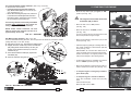
NOTE: During clip insertion, the movement of the teeth may NOT be simultaneous
because the two clamps operate independently.
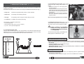
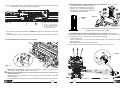
4.4.2) Adjusting the height of the front of the machine (Ref. to Fig. 8)
– To raise the machine, turn the graduated
adjuster (42) anticlockwise; to lower the
machine, turn the graduated adjuster
(42) clockwise using the graduated scale
to achieve precise positioning.
graduated
scale
FIG. 11c
33
NOTE:
movement of one of the
clamps is schematically
shown in the illustrations; the
other will have an identical
and opposite movement.
– After insertion, pull the control lever to "EXTRACT" position for teeth (33) reversal (see
Fig. 11c).
– Raise the machine and go onto the next set of rail clips and repeat the above operations.
4.5.2) Simultaneous extraction of 2 rail clips
42
43
43
FIG. 8
Note: It may be easier to use the adjuster (42) with the clamp unit
partially disconnected from the carriage.
4.4.3) Adjusting the vertical alignment of the machine (Ref. to Fig. 9)
The distance of the teeth (33) from the retention plates of the RE-clips must be the same
for both clamps. If this is not the case, adjust support wheel (38):
– Loosen handle (39).
– Lower or raise the rod (37) to change the vertical angle of the machine and achieve
correct alignment.
– After adjustment, tighten the handle (39) well.
It may also be necessary to change the machine alignment on track bends.
38
FIG. 9
37
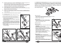
FIG. 12
–
–
46
With engine switched off, manually turn upwards the insertion stop (46) in to its
rest position, as allowed by the pin (see Fig. 12);
Before extracting RE-clips it is important that the insertion stop (46) is in
horizontal position.
Otherwise the stroke of both rams is not enough to locate the machine on the clip
retention plates.
During extraction the insertion stop (46) must be kept in rest position to avoid obstacles.
16
13
39