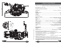
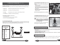
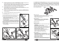
1
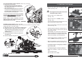
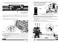
www.cembre.com
Cembre S.p.A.
Via Serenissima, 9
25135 Brescia (Italia)
Telefono: 030 36921
Telefax: 030 3365766
E-mail: [email protected]
www.cembre.it
Cembre España S.L.
Calle Verano, 6 y 8 - P.I. Las Monjas
28850 Torrejón de Ardoz - Madrid (España)
Teléfono: 91 4852580
Telefax: 91 4852581
E-mail: [email protected]
www.cembre.es
Cembre Ltd.
Dunton Park
Kingsbury Road, Curdworth - Sutton Coldfield
West Midlands B76 9EB (Great Britain)
Tel.: 01675 470440 - Fax: 01675 470220
E-mail: [email protected]
www.cembre.co.uk
Cembre AS
Fossnes Senter
N-3160 Stokke (Norway)
Phone: (47) 33361765
Telefax: (47) 33361766
E-mail: [email protected]
www.cembre.no
Cembre S.a.r.l.
22 Avenue Ferdinand de Lesseps
91420 Morangis (France)
Tél.: 01 60 49 11 90 - Fax: 01 60 49 29 10
B.P. 37 - 91421 Morangis Cédex
E-mail: [email protected]
www.cembre.fr
Cembre GmbH
Heidemannstraße 166
80939 München (Deutschland)
Telefon: 089/3580676
Telefax: 089/35806777
E-mail: [email protected]
www.cembre.de
cod. 6261357
This manual is the property of Cembre: any reproduction is forbidden without written permission.
Cembre reserve the right to modify the specifications in this manual without prior notice.
13 M 083 E
Cembre Inc.
Raritan Center Business Park
181 Fieldcrest Avenue
Edison, New Jersey 08837 (USA)
Tel.: (732) 225-7415 - Fax: (732) 225-7414
E-mail: [email protected]
28
www.cembreinc.com
ENGLISH
Certified Quality
Management System
Certified Environmental
Management System
Certified Occupational
Health & Safety
Management System
PANDROL "RE-CLIP" MACHINE
with braking system
OPERATION AND MAINTENANCE
MANUAL
1
TG 0350
2
1
xxxxxx
Pump unit
serial nr.
3
WARNINGS
1 Before using the machine read the instructions contained in
this manual carefully.
SAVE THESE INSTRUCTIONS: this manual contains important
safety and operating instructions for the machine.
2 During operation keep your hands outside the danger area.
3 Always wear protective glasses and working gloves.
650
Avoid wearing clothes which may present a risk to personal
safety.
1900
Only authorised personnel shall start or operate the machine.
The user shall not modify the design or configuration of the
machine.
Cannot be used over switches and crossings.
Not to be used near live d.c. conductor rail.
Not to be used for any purpose other than for which machine is
designed.
1000 max.
Do not exceed walking pace when pushing the machine.
The machine fulfils the requirements
of EN 13977:2005 + A1:2007.
EN 13977
FIG. 17 – DIMENSIONS (mm)
2
27
1. GENERAL CHARACTERISTICS
– Application range: suitable for the insertion and extraction of Pandrol RE-clip* ø16 mm
used with 75 mm bases on standard-gauge rails (1435 mm).
850
– Developed force (single clamp) .................................................................... 29.000 N
– Resistance between rail and wheel: .............................................................. ≥1 MΩ
– Dimensions: ...................................................................... (see Fig. 17, pages 26-27)
1400
(*) "Pandrol RE-clip" is a Pandrol Ltd trademark.
xxxxxx
Clamp
unit
serial nr.
26
–
–
–
–
–
–
Weight:
complete machine: ............................................................................................. 112 kg
pump unit: ............................................................................................................ 50 kg
clamp unit: ............................................................................................................ 48 kg
carriage: ................................................................................................................. 9 kg
3rd wheel bar: ...................................................................................................... .. 5 kg
–
–
–
–
–
–
–
–
–
–
–
–
–
Combustion engine:
type: ............................................................... 4-stroke, overhead valves, one cylinder
model: ................................................................................... Honda GX 160K1-QMD6
displacement: ................................................................................................... 163 cm3
power: ................................................................................................................... 4 kW
revs.: .............................................................................................................. 3700 rpm
exhaust emissions: ....................HC+NOx = 10,53 gr/kW.h and CO = 433,37 gr/kW.h
fuel consumption: ..................................................................................... 0.9 litres/hour
fuel: ................................................................................unleaded regular grade petrol
tank capacity: ................................................................................................... 3.6 litres
recommended oil: ................................................................... SAE 10W-30 (0.6 litres)
clutch: ............................................................... centrifugal with automatic intervention
start: ........................................................................ by rope pull with automatic rewind
–
–
–
–
–
Hydraulic pump:
max. pressure: ................................................................................................. 42 MPa
oil supply: ............................................................................................ 5,6 litres/minute
speed: ............................................................................................................ 3700 rpm
recommended oil: ...................................................... AGIP ARNICA 32 or equivalents
– Acoustic noise (Directive 2006/42/EC, annexe 1, point 1.7.4.2 letter u)
– The continuous equivalent weighted level (A) of noise pressure
at the working place LpA is equal to .................... 84,9 dB (A), uncertainty KpA ± 0,9 dB
– The maximum value of instantaneous weighted noise pressure C
at the working place LpCPeak is .............................< 130 dB (C)
– The level of noise force produced
by the machine LWA is equal to ........................... 99,6 dB (A), uncertainty KWA ± 0,9 dB
– Risks due to vibration (Directive 2006/42/EC, annexe 1, point 2.2.1.1)
Tests carried out in compliance with the indications contained in ISO 5439 Standard,
and under operating conditions much more severe than those normally found, certify that
the weighted root mean square in frequency of the acceleration the upper limbs
are exposed is 3.7 m/sec2.
3
2. MACHINE DESCRIPTION (Ref. to Fig. 1)
01
02
03
04
05
06
07
08
09
10
11
12
13
14
15
16
17
18
19
20
21
22
23
24
25
26
27
28
29
30
31
32
33
34
35
36
37
38
39
40
41
42
43
44
45
46
–
–
–
–
–
–
–
–
–
–
–
–
–
–
–
–
–
–
–
–
–
–
–
–
–
–
–
–
–
–
–
–
–
–
–
–
–
–
–
–
–
–
–
–
–
–
7. RETURN TO Cembre FOR OVERHAUL
In the case of a breakdown contact our Area Agent who will advise you on the problem
and give you the necessary instructions on how to dispatch the machine to our nearest
TRANSPORT HANDLES
LIFTING POINT IN NEUTRAL POSITION
HYDRAULIC PUMP OIL TANK
ACCELERATOR
WORKLIGHT ON/OFF SWITCH
STOP/EMERGENCY BUTTON
CLAMP CONTROL LEVER
HANDLEBAR
QUICK RELEASE MALE AUTOMATIC HYDRAULIC COUPLER
QUICK RELEASE FEMALE AUTOMATIC HYDRAULIC COUPLER
HYDRAULIC PUMP
PUMP UNIT FASTENING/RELEASE KNOB
WORKLIGHT
ELECTRICAL TERMINAL BOX
ENGINE
PUMP UNIT FASTENING/RELEASE KNOB
OIL COOLING RADIATOR
FRAME
CLAMP UNIT LOCATING PINS
TRANSPORT HANDLE
PUMP UNIT LOCATING PINS
QUICK RELEASE MALE AUTOMATIC HYDRAULIC COUPLER
BRAKE RELEASE DEVICE LOCK
QUICK RELEASE FEMALE AUTOMATIC HYDRAULIC COUPLER
REAR HEIGHT ADJUSTMENT KNOB
KNOB LOCK HANDLE
WHEEL LOCK/RELEASE KNOB
GAS SPRING RIGHT SIDE
TRANSPORT HANDLES
REAR WHEEL
GAS SPRING LEFT SIDE
FLEXIBLE HOSES
INSERTING/EXTRACTING TOOTH
HYDRAULIC RAM
BRAKE RELEASE DEVICE
YELLOW LOCATOR PLATE
BAR
SUPPORT WHEEL
SUPPORT WHEEL ADJUSTMENT LEVER
TRANSPORT HANDLES
CONNECTING ROD FASTENING/RELEASE KNOB
GRADUATED FRONT HEIGHT ADJUSTER
CLAMP UNIT FASTENING/RELEASE KNOBS
FRONT CARRIAGE WHEELS
BRAKE RELEASE HANDLE
INSERTION STOP
service Centre; if possible, attach a copy of the Test Certificate supplied by Cembre
together with the machine or, if no other references are available, indicate the approximate
purchase date and machine serial number.
8. OPTIONAL ACCESSORIES
- MPC6 PRESSURE GAUGE code 2595209
To check maximum pressure valve setting.
- PROTECTIVE COVER FOR PANDROL CLIP MACHINE:
TARPCOVER 019-PCM code 2593275
(material: Polyethylene HDPE
UV stabilised, + 70 °C to - 40 °C)
4
25
24
Replacement
Visual & manual checks of integrity
Braking device & wheels
Replacement
Check reservoir level
(Top up if necessary)
Replacement
Visual & manual checks of integrity
Replacement
Visual & manual checks of integrity
Complete tightening
Visual & manual checks
(tighten if necessary)
Visual check of integrity
Replacement
Complete tightening
Visual & manual checks of
(tighten if necessary)
Store the machine in dry place
protecting it from shocks
and dust
General cleaning with a clean cloth,
paying attention to remove settled dirt
ACTION
Gas springs
Light bulbs and fuse
Hydraulic oil
Inserting teeth (33)
Locator plate (36)
Rubber dampers
of the machine
Hydraulic couplers
Flexible hose
Bolts and nuts
Complete machine
ITEM
Performed at the prescribed intervals or at the number of indicated
working hours or at the occurrence of indicated extraordinary events
PERIODIC OVERHAUL
Ô
Ô
Ô
Ô
Ô
Ô
Ô
At every use
Ô
Ô
50 hours
Ref. to § 6.1.1
Ô
Ô
Ô
Ô
Presence
of evident
signs of wear
Ô
In case of
breakage
Ô
Long periods
of inactivity
02
PUMP UNIT
14
36
37
5
34
03
15
13
12
19
22
46
40
41
04
11
20
32
39
38
44
FIG. 1 - MACHINE DESCRIPTION
05
01
26
43
06
45
07
18
17
08
16
09
35
10
23
21
24
25
27
28
29
CLAMP UNIT
30
31
3 WHEEL BAR
rd
33
42
CARRIAGE
– Pump unit:
combustion engine/hydraulic pump for clamp operation.
– Clamp unit:
for inserting and extracting RE-clips.
6.1.4) Changing the gas springs (Ref. to Fig. 15)
Replace the gas springs when required as
follows:
– Release the wheel arm so the springs are in
extended position.
– Using a flat-blade screwdriver, lift the retention
collar at the end of the spring, pulling with force
at the same time to release the spring from its
gas spring
locating pins.
– Fit the new spring on the same pins and press
with force until this is properly fitted in the
original position.
– Carriage:
for supporting and moving the machine along the track.
Note: the two springs differ from one another.
3. UNPACKING THE MACHINE (Ref. to Fig. 1)
To reduce overall dimensions and weight during transport, the machine is supplied disassembled as four units.
It consists of four main sections which can be easily assembled/disassembled (Ref. Fig. 1):
– 3rd wheel bar: for stability and vertical positioning.
FIG. 15
The machine is supplied complete with:
– 1pc spark plug key.
– 1litre hydraulic pump oil (do not use in engine).
– 1pc 12V - 21W spare worklight bulb.
6.1.5) Maximum pressure valve (Ref. to Fig. 16)
The hydraulic pump features a maximum pressure valve, factory set and sealed at 42 Mpa.
3.1) Transporting the units
The four units are well balanced for easy transportation in accordance with the table and
diagrams in Fig. 2. For uniform weight distribution and to transport the pump and Clamp
units, always use the transportation handles provided to lift the units.
Distributed Load
per Person
(kg)
A
B
C
D
E
F
24
24
9
5
25
25
NEVER CHANGE THE MAXIMUM
PRESSURE VALVE SETTING AS
THIS MAY CAUSE SERIOUS DAMAGE
TO THE MACHINE.
B
CLAMP UNIT
Maximum
pressure
valve
To check correct valve setting, a special pressure
testing gauge is available (Ref. to § 8).
6.2) Routine maintenance of the engine
A
screwdriver
FIG. 16
Checks and periodical assistance are indispensable to ensure smooth engine operation.
Refer to the "Honda user's manual" supplied with the machine, for the following operations:
– Oil change
– Air filter assistance (see double-element type)
– Cleaning sediments from sump
– Spark plug cleaning; recommended plugs BPR6ES (NGK) or W20EPR-U (DENSE)
– Minimum carburettor setting
6.3) Long periods of inactivity
– Store the machine in a dry environment, and adequately protect it against accidental
damage and contamination.
– For information on the combustion engine, refer to the "HONDA user's manual".
6
23
6.1.2) Topping up the oil in the hydraulic pump (Ref. to Fig. 14a)
Periodically check the level of the oil in the hydraulic pump. The oil should always be visible
03
inside the tank (03). If the level is low, top up
with the specific oil recommended:
– Unscrew the cap and add sufficient oil to fill the
tank; do not exceed the oil level.
– After topping up, tightly screw the cap back on.
D
C
Always use clean recommended oil, see § 1.
Do not use old or recycled oil.
Do not use hydraulic brake fluid.
FIG. 14a
3rd WHEEL BAR
CARRIAGE
6.1.3) Changing worklight bulbs (Ref. to Fig. 14b-d)
– Loosen the locking nut (Fig. 14b).
– Turn worklight upwards and remove the two
locking
screws in the lens (Fig. 14c) using a screwdriver.
nut
– Remove the faulty bulb and replace with another
having the same specifications: 12V - 21W
– Replace lens and tighten the two screws.
– Reset worklight to original position and tighten
the nut.
The light bulb power circuit is protected by a
fuse against overcurrents and short-circuits.
In case of a fault:
– Remove the 4 screws from the lid of the terminal
box (14) using a screwdriver.
– Pull out fuse carrier and open it (Fig. 14d).
FIG. 14b
– Replace faulty fuse with a new one with the same
specifications: 6,3A - 250V
– Push fuse carrier back, replace lid and tighten 4
screws.
E
F
PUMP UNIT
FIG. 2 – TRANSPORTING THE UNITS
4. INSTRUCTIONS FOR USE (Ref. to Fig. 4)
light bulb
12V - 21W
14
4.1) Assembly/disassembly of the machine
Select the rail to be worked on and the direction of operation, then assemble the machine
as follows, referring to Fig. 4:
pin (27) engaged and wheel (30) blocked, raise the clamp unit by means of the
– With
handles (20 and 29) and rest this on the selected rail, positioning it between two
sleepers.
– Rest the support carriage on the track and then pull and turn the fastening/release
knobs (43). Lift the clamp unit by means of the handle (20) and locate (19) pins fully
into their carriage housing as far as the stop.
Release the knobs (43) to lock the clamp unit.
fuse-carrier
1
2
FIG. 14d
FIG. 14c
22
7
3–
4–
5–
6–
Pull and turn the knob (41), insert the 3rd wheel bar in the carriage housing as far as
the stop, aligning the hole in the end of the rod with the pin knob.
Release the knob (41) and the wheel (38) which will act as a support on the opposite
rail so the assembly is stable and able to slide along the rail; the rod can be fitted in
carriage from either side for convenience in selecting the direction of work.
Pull and turn the knobs (12 and 16) at the base of the pump unit.
Lift the pump unit by means of the handles (01) and handlebar (08).
Rest the pump unit on the clamp unit and align the pins (21) with the relevant locating
holes on the under side of the pump unit.
Release the knobs (12 and 16) for locking.
Restore the oil delivery/return hydraulic circuit, connecting the flexible hoses by
means of the quick couplings (09 and 10) to the respective connectors (24 and 22)
on the clamp unit.
Connect the brake release device (35) (Ref. to § 4.1.1)
4.1.1) Braking device (Ref. to Fig. 3a, 3b, 3c, 5)
Rear Carriage wheel (A):
(A)
FIG. 3a
To run the machine along the rail, it is necessary to connect
the brake release device (35); proceed as follows:
– Introduce end part (A) into slot seat (B) located above
the rear wheel of the clamp unit.
– Pull the handle (C) upwards, release it in position than
push until is locked.
– Press the handle (45) to verify the correct engagement
and disengagement of release pin (P) from the wheel.
During the disassembly of the machine, before removal
of the pump unit, the brake release device must be disassembled as follows:
– Pull the handle (C) and disconnect the end part (A)
from slot seat (B).
Before every use:
– Check wheel for resistance, wheel should not be free rotating.
– Ensure wheel is clean, removing any dirt or mud.
– Check for signs of damage.
35
A
Every 6 months:
– Check for excessive braking on wheel. Wheel
should roll along track when pushed, wheel will
slide if excessive braking occurs.
Clamp unit wheel
B
FIG. 3b
6.1.1) Maintenance of braking device (only for versions of machine with braked wheels)
The braking system is of robust construction and will require very little maintenance,
however the following routine checks should be performed. Dust, sand and dirt are a
danger for any mechanical device. Avoid putting the machine on muddy ground.
After every use, the machine must be wiped with a clean cloth, taking care to
remove any residue, especially around moving parts.
FIG. 3c
C
P
8
Before every use:
– Check cable, linkages, springs and wheel for signs
of damage.
– Check linkages are free moving.
– Ensure brake cable moves without resistance.
– With brake released, check that wheel rotates freely.
– Check that when handlebar lever is in the raised
position, the brake is engaged.
– Ensure that wheel is clean of dirt and mud.
– Check that, before assembly, the wheel dos not
rotate one full turn in either direction.
– Ensure coupling is free of dirt and mud.
Every 6 months
– Check wheel pockets for excessive wear.
If braking effectiveness is compromised, replace wheel.
– Check extension spring (see figure) on brake release
handle (45) are undamaged.
– Check for wear on pivots.
– Ensure fasteners are secure.
– Check for wear on coupling, parts should mate securely.
– Clean all moving parts and lubricate as required.
21
45 extension
spring
27
23
21
22
6. MAINTENANCE
RAILS
1
19
2
16
21
4
20
12
5
10
24
09
6
30
08
29
TROUBLESHOOTING
When the starting cable is pulled, the engine fails to start:
Is the Stop/Emergency button (06) released? (see § 4.3).
Is there enough oil in the combustion engine?
– The engine features an oil alert system to prevent damage caused by too little
oil. Before the level drops below safe limits, the alarm system automatically
stops the engine.
Refer to the "HONDA owner’s manual" for the type of recommended oil and topping up.
THE HYDRAULIC OIL SUPPLIED WITH THE MACHINE IS INTENDED ONLY FOR
USE IN THE HYDRAULIC PUMP AND IS MUST NOT BE USED IN THE ENGINE.
Is the fuel stopcock open?
Is there fuel in the tank?
Is fuel reaching the carburettor?
– To check, loosen the carburettor drainage screw with fuel cock open and refer to the
"HONDA owner’s manual" .
Is the spark plug producing a spark?
– Remove the plug cap, clean around the plug and remove the plug using the spanner provided.
– Fit the plug back in the cap.
– Move button (06) to ON.
– After earthing the side electrode, pull the starting cable and check to see whether the
plug produces a spark.
If the engine still fails to start, contact Cembre (see § 7).
01
All electrical and mechanical maintenance shall only be carried out by authorised
persons in accordance with a safe system of work and Cembre instructions.
3
43
41
Before servicing or removing any parts of the machine, stop the engine and
allow it to cool. Always remove the spark plug cap from the spark plug when
servicing the engine to prevent accidental starting.
20
9
38
Regularly perform the following operations or inspections:
– Tighten all bolts.
– Check the integrity of the 3 rubber dampers which reduce vibration caused by the enginepump.
– Lubricate the clamp piston rods.
– If necessary change insertion/extraction teeth (33) and locator plates (36) as these become
damaged or worn by prolonged or improper use.
DIRECTIO
N OF
MOVEMEN
T
At the end of each day, clean the machine carefully using a clean cloth, being careful
to eliminate all dirt or any oil stains, especially near the moving parts such as the clamp
teeth and piston rods and wheels. Do not rest the machine or units directly on dusty or
muddy ground.
FIG. 4 –
SEQUENCE OF ASSEMBLY
6.1) Routine maintenance of the machine
4.1.2) Disassembly of the machine (Ref. to Fig. 4 and 4a)
To disassemble the machine:
– First lower the rear part and lock with pin
(27), block wheel (30) then reverse the process described in § 4.1.
– Before disconnecting the pump unit, make sure
to have disconnected the hydraulic circuit and
the braking device; locate the hoses in support
(S) on the frame of the pump unit.
5. STARTING THE ENGINE
– Move the stop button (06) (see § 4.3) to "ON"
position (see Fig. 13a).
FIG. 13a
06
The
engine will not start unless the
red button (06) is lifted.
If necessary, with the machine fully assembled
and the motor switched off, the clamps can
always be opened or closed manually.
– Move the fuel cock to "ON" position
(see Fig. 13b).
NOTE: Under normal conditions, the time
taken to remove the machine from the rail is
approximately 60 seconds.
S
– Move the air lever to "CLOSE" position
(see Fig. 13b).
Do not use the air lever if the engine is hot and
the air temperature is high enough.
FIG. 4a – SUPPORT
4.2) Moving the machine (Ref. to Fig. 4b)
To move the machine along the track, the rear part must be raised to prevent the clamps
fouling fitted clips. To do this, simply:
45
1 - Pull and turn knob (27). The wheel arm will be freed.
2 - Slightly raise the machine by means of handlebar
(08); lifting will be made easier by the two gas
springs, then release the knob (27) to lock the
machine fully up.
08
3 - Press brake release handle (45) against the
handlebar (08).
4 - Push the machine along the rail.
3
FIG. 13b
– Move the accelerator control lever (04) to mid
stroke (see Fig. 13c).
– Start the engine by pulling the starting cable until a certain resistance is felt and then pull with
force (see Fig. 13d).
IMPORTANT: Do not allow the cable knob to
return forcefully and knock against the engine.
Return this slowly to its original position. This
will prevent damage to the starting device.
Fuel cock
OFF
ON
FIG. 13c
04
– As the engine heats up, gradually move the air
lever to "OPEN" position (see Fig. 13b)
2
– Move the accelerator control lever (04) fully forward to achieve the correct rpm (see Fig. 13c).
4
27
1
– To stop the engine in emergency condition,
press button (06).
– To stop the engine in normal conditions:
move the accelerator control lever (04) fully
back.
Press the button (06).
Move the fuel cock to "OFF".
FIG. 4b – MOVING THE MACHINE
10
Air lever
CLOSE
OPEN
19
FIG. 13d
Starting
cable knob
– After removal, pull the control lever to "INSERT" position for forward movement of teeth
(33) (see fig. 12d).
4.3) Controls (Ref. to Fig. 5)
After gripping the handlebar (08), the operator can easily access all the unit controls and,
more specifically:
– Accelerator control lever (04): changes engine rpm.
– Worklight ON/OFF switch (05): in case of night work or bad lighting, the clamping
area can be illuminated by these side mounted lamps.
– Stop/emergency button (06) in a very visible position and easy to operate to stop the
unit normally and in case of an emergency.
NOTE: when this button is pressed it remains in OFF position. To start the engine, the
button should be turned clockwise so that it lifts automatically into the ON position.
33
FIG. 12d
NOTE:
movement of one of the
clamps is schematically
shown in the illustrations;
the other will have an
identical and opposite
movement.
– Raise the machine and go onto the next RE-clips.
– Repeat the above operations.
The engine will not start unless the red button (06) is lifted.
– Clamp control lever (07) with swinging movement, for operating the clamps:
- right side for inserting RE-clips, "INSERT" position
- left side for extracting RE-clips, "EXTRACT" position
– Brake release lever (45): for safety reasons, the machine is equipped with an automatic braking device. This device is always engaged within the rear wheel.
By pressing handle (45), the brake is released enabling movement of the machine along
the rail.
04
06
05
07
EXTR
ACT
FIG. 5 – CONTROLS
18
11
T
INSER
08
45
4.4) Setting the machine (Ref. to Fig. 6)
Before use, always check the height of the clamps with respect to the RE-clips.
Taking a retention plate as a reference point, check the position of the clamps with respect
to the plate itself.
In working condition, both clamps must be:
– Perfectly horizontal with respect to the rail.
– The insertion/extraction tooth (33) must be able to slide horizontally with 3-4 mm clearance above the retention plate (see Fig. 6).
Make sure the locking knob (27) of the wheel is released (see § 4.2).
– Make sure the teeth (33) of the clamps are moved fully forwarded by pulling the control
lever to the right in "INSERT" position.
– Completely lower the machine, positioning the insertion contrast, marked by the
yellow locator plates (36) near the RE-clip retention plates (see Fig. 12a).
FIG. 12a
33
RE clip
retention plate
– Pull the control lever (07) to the left in "EXTRACT" position: to gradually move the teeth
forwards with consequent extraction of both RE-clips (see Fig. 12b and 12c).
When performing the extraction operation, each clamps teeth (33) will move in opposite
directions.
33
˜
36
3 - 4 mm
FIG. 6
RE-clip retention plate
To adjust, proceed as follows:
4.4.1) Adjusting the rear height of the machine (Ref. to Fig. 7)
FIG. 12b
– Loosen the handle (26).
– To raise the machine, turn the adjustment knob (25) clockwise.
– To lower the machine, turn the
adjustment knob (25) anticlockwise.
– After making adjustment, tighten
the handle (26) well.
33
NOTE: During clips extraction, the movement of the teeth may NOT be simultaneous
because the two clamps operate independently.
25
26
FIG. 12c
FIG. 7
12
17
33
NOTE: During clip insertion, the movement of the teeth may NOT be simultaneous
because the two clamps operate independently.
4.4.2) Adjusting the height of the front of the machine (Ref. to Fig. 8)
– To raise the machine, turn the graduated
adjuster (42) anticlockwise; to lower the
machine, turn the graduated adjuster
(42) clockwise using the graduated scale
to achieve precise positioning.
graduated
scale
FIG. 11c
33
NOTE:
movement of one of the
clamps is schematically
shown in the illustrations; the
other will have an identical
and opposite movement.
– After insertion, pull the control lever to "EXTRACT" position for teeth (33) reversal (see
Fig. 11c).
– Raise the machine and go onto the next set of rail clips and repeat the above operations.
4.5.2) Simultaneous extraction of 2 rail clips
42
43
43
FIG. 8
Note: It may be easier to use the adjuster (42) with the clamp unit
partially disconnected from the carriage.
4.4.3) Adjusting the vertical alignment of the machine (Ref. to Fig. 9)
The distance of the teeth (33) from the retention plates of the RE-clips must be the same
for both clamps. If this is not the case, adjust support wheel (38):
– Loosen handle (39).
– Lower or raise the rod (37) to change the vertical angle of the machine and achieve
correct alignment.
– After adjustment, tighten the handle (39) well.
It may also be necessary to change the machine alignment on track bends.
38
FIG. 9
37
FIG. 12
–
–
46
With engine switched off, manually turn upwards the insertion stop (46) in to its
rest position, as allowed by the pin (see Fig. 12);
Before extracting RE-clips it is important that the insertion stop (46) is in
horizontal position.
Otherwise the stroke of both rams is not enough to locate the machine on the clip
retention plates.
During extraction the insertion stop (46) must be kept in rest position to avoid obstacles.
16
13
39
4.5) Operation
Before use, always check:
– The integrity of the machine as a whole:
– The correct assembly of the units making up the machine.
– Correct connection of the quick couplings.
– Correct level of oil in pump.
– For any oil leaks in the hydraulic circuit (radiator, hoses, pump).
– The flexible hoses are in good condition and show no signs of wear or crushing.
– The protection devices in the clamp areas are firm and show no evidence of
breakage.
– The engine tank cap is tight. Petrol is highly inflammable and can explode.
– Start the engine (see § 5).
– With rear wheel locking knob (27) released, push the machine to the rail clips on which
operations are to be performed (see § 4.2).
– Make sure the teeth (34) of the clamps are moved fully back by pulling the control lever
to the left "EXTRACT".
– Completely lower the machine, positioning the insertion contrast, marked by the
yellow locator plates (36) near the rail clip retention plates (see Fig. 11a).
4.5.1) Simultaneous insertion of 2 rail clips (Ref. to Figs. 11a, 11b, 11c)
– Position the rail clips in the retention plate eyelets, on both sides of the rail.
Pandrol
RE-clip
FIG. 11a
Retention
plate
With engine switched off,
manually turn downwards
the insertion stop (46) into the
vertical position, as allowed
by the pin (see Fig. 10). During
insertion the stroke of the rams
will be limited by the insertion
stop against the contrast;
Before inserting RE-clips
it is important that the
insertion stop (46) is
in vertical position.
this stop system avoids
inserting the clips too
46
deeply in the retention plate,
ensuring the minimum distance
required to install clips appropriately.
RE-clip retention plate
33
– Pull the control lever to the right "INSERT" position to gradually move the teeth forwards
with consequent insertion of both rail clips (see Fig. 11b).
When performing the insertion operation, the teeth of each clamp (34) will move in opposite directions.
Rail
–
36
FIG. 11b
FIG. 10
14
15
33