1
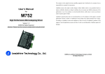
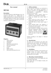
ASR58
1 Safety summary
User Manual
Safety
• observe the professional safety and accident prevention
regulations applicable to your country during device
installation and operation;
• installation has to be carried out by qualified personnel
only, without power supply and stationary shaft;
• the encoder must be used only for the purpose appropriate
to its design;
• high current, voltage and rotating parts can cause serious
or fatal injury.
Electrical safety
• switch OFF the voltage before connecting the device;
• connect according to the chapter 5: “Electrical
connections”;
• according to the 89/336/CEE norm on
electromagnetic compatibility, following
precautions must be taken:
9 before handling and installing, discharge electrical charge
from your body and tools which may come in touch with
the device;
9 power supply must be stable without noise, install EMC
filters on device power supply if needed;
9 always use shielded and twisted cables if possible;
9 avoid cables runs longer than necessary;
9 avoid running the signal cable near high voltage power
cables;
9 mount the device as far as possible from any capacitive or
inductive noise source, shield the device from noise source
if needed;
9 minimize noise by connecting shield or connector housing
to ground (GND). Make sure that ground (GND) is not
affected by noise. The shield connection point to ground
can be situated both on the device side and on user’s side.
The best solution to minimize the interference must be
carried out by the user.
Mechanical safety
• solid shaft: use a flexible coupling to connect encoder to
motor shaft respecting the coupling misalignment
tolerances;
• do not disassemble the encoder;
• do not tool the encoder or its shaft;
• do not subject the encoder and the shaft to knocks or
shocks;
• respect the environmental characteristics of the product.
ROTACAM ASR58
Description
ROTACAM is an absolute encoder purposely
designed to produce electrical phase signals that are
necessary for the working of any automatic
machine.
Instead of using special or adjustable mechanical
cams to drive micro switches or proximity switches,
the ON/OFF switching points are programmed via
software by a PC in correspondence of the desired
angles.
The reliability of correct working is warranted by a
microprocessor of advanced conception
that
permits to memorize up to 16 different programs
that can contain 1920 cams.
Chapters
1
2
3
4
5
6
Safety summary
Identification
Installation
Electrical connections
Setup
Programming software
2 Identification
The device can be identified by the label's data
(ordering code, serial number). This information is
listed in the delivery document. For technical
features of the product, refer to the technical
catalogue.
MAN ASR58 I_E 1.5.doc
9
www.lika.it
www.lika.biz
ASR58
4 Electrical connection
3 Installation
Install the device according to the provided
protection level. Protect the system against knocks,
friction, solvents and respect the environmental
characteristics of the unit.
DSub 25 pin connector pinout:
3.1 Assembly instructions
Pin
1
2
3
4
5
6
7
8
9
10
11
12
13
Install the encoder with fixing clamps (ordering
code LKM 386):
(1)
(2)
fixing clamps kit, supplied with screws
flexible coupling
Function
Out 1
Out 2
Out 3
Out 4
Out 5
Out 6
Out 7
Out 8
Out 9
Out 10
Out 11
Out 12
Out 13
Pin
14
15
16
17
18
19
20
21
22
23
24
25
Function
Out 14
Out 15
Out 16
Load Prg
Sel. Prg.20
Sel. Prg.21
Sel. Prg.22
Sel. Prg.23
Zero Setting
Complementary
+10Vdc +30Vdc
0 Vdc
DSub 15 pin connector pinout:
In order to guarantee the maximum life of the
mechanical parts of the encoder, we recommend to
use a flexible coupling between the encoder and the
motor shaft.
Pin
Function
1
n.c.
2
n.c.
3
n.c.
4
Analogue output*
5
Speed
6
GND
7
Fault
8
GND (RS232)
n.c. = Not connected
* option
IMPORTANT:
You are strongly advised not to carry out any
mechanical operations (drilling, milling, etc.) on the
encoder’s shaft. This could cause serious damages to
the internal parts and the immediate warranty loss.
Pin
9
10
11
12
13
14
15
Function
n.c.
n.c.
GND
RxD (RS232)
TxD (RS232)
+10Vdc +30Vdc
0 Vdc
NOTE:
• Power supplies of both connectors (pin 14 + 15
and respectively 24 + 25) are connected
together.
• Program selection inputs (pin 18, 19, 20 and 21)
are internally connected to GND with pull down
resistances.
• GND (RS232) is not connected to 0Vdc.
MAN ASR58 I_E 1.5.doc
10
www.lika.it
www.lika.biz
ASR58
4.1 RS232 serial interface
An application software for encoder setup with
RS232 interface (pin 8, 12, 13 of DSub 15 pin
connector) is available on the web site www.lika.biz
> products > rotary transducers > absolute
encoders.
PC
pin 2
pin 3
pin 5
5 Setup
5.1 Parameter description
Load Prg Load program
Permits to load the selected program. Bring the
signal Load Prg (PIN 17) to GND for at least 10 ms.
The program will be automatically loaded at
ignition.
ASR58
pin 13
pin 12
pin 8
Sel. Prg. 2x Select program
You can select the program using a binary code of 4
PIN (18, 19, 20, 21). See the example below: code for
the selection of program n° 5:
PIN
Value
Binary
21
23
0
20
22
1
19
21
0
18
20
0
=4
Program n°5 = Binary code + 1.
Zero Setting
The output value is set to zero (reset) by a signal of
PLC or other device. The reset signal (PIN 22) must
be at logical level HIGH from +10Vdc to + 30Vdc for
100 µs minimum.
Make sure that RxD of the PC is connected to the
TxD of the device and that TxD of the PC is
connected to the RxD of the device.
Technical data:
Function
Baud rate
Data bits
Parity bit
Stop bit
Flow control
ATTENTION:
The zero setting command modifies only the
position value of the single program in use (not
those of the other 15).
Data
9600
8
No
1
No
Complementary Counting direction
Allows the anticlockwise counting of the encoder.
Connect PIN 23 with PIN 24 (+10Vdc +30Vdc).
Analogue output
The analogue output in voltage is optional (PIN 4).
On request we supply following ranges:
0 Vdc ÷ +10Vdc
0 Vdc ÷ +5Vdc
95Vdc ÷ +5Vdc
To activate the analogue output it is necessary to
program one and just one cam in the output n° 1.
Speed Speed sensing signal.
Square wave 1800 PPR for speed survey.
MAN ASR58 I_E 1.5.doc
11
www.lika.it
www.lika.biz
ASR58
Fault State of outputs
The fault signal (PIN 7) indicates the state of the 16
outputs. State ON indicates that:
• the encoder is receiving the program
• the selected program is loading in EPROM
• the selected program does not exist.
6 Programming software
RxD, TxD (RS232)
Opto9insulated serial gate RS232
programming and display by PC.
6.2 Software installation
Before installing the utility software, close any other
application and uninstall the old versions.
for
6.1 PC encoder connection
Connect according to the chapter 4: “Electrical
connections”.
the
To install the software click twice on “Setup.exe".
The procedure will ask you, where to save the
application.
Copy the example files (*.txt) from program
directory (C:\program\Rotacam) to work directory
(C:\Lika\rotacam).
5.2 Accessories
• Programming software.
• External AC/DC power supply used to give
voltage to the encoder during the programming
on PC.
• Hand held programmable terminal in order to
modify the programs stored in the encoder
without taking down the encoder from the
machine and without need of a PC.
6.3 Main window
5.3 Reading position through RS232
To read actual value send the following message:
Byte
Value
0
128
1… 17
0
18
CHK
The encoder will reply with a message of 19 bytes:
Byte
Value
0
128
1
0
2
LSB of actual position
3
MSB of actual position
4
n° of active program
5
n° of programmed cam
6… 7
0
8
LSB output pattern
9
MSB output pattern
10… 17
0
18
CHK
“Off line” button is used to stop serial
communications and release serial gates for other
applications.
The position, the active output (output status), the
program in use and the cams programming are
visualized in the main window.
Between the “Off line” button and the position edit
there is a vertical bar that shows the quality of
communication, when it is green it means the
communication is good, if the bar changes its color
(yellow or red) it means that there are some
problems in the serial communication (cable too
long, noise, etc.).
If the visualization is intermittent, try to change
Filter parameter (see next chapter).
If there is no communication, the vertical bar will be
red and the position edit will display dashes.
CHK Checksum
Byte used for the control of the correct message
transmission. The CHK value is the unsigned sum of
bytes 0917.
MAN ASR58 I_E 1.5.doc
12
www.lika.it
www.lika.biz
ASR58
The serial gate in use is highlighted on the title bar.
If you reduce the main window to icon, the position
is visualized on the application bar.
6.4 Programming window
6.3.1 Tools menu
Programming
It opens the window used to manage, transmit and
modify the encoder programs.
6.3.2 Settings menu
Model
Select the ASR encoder model connected to the PC.
The standard encoder is ASR58, but the software
can work with the old ASR6 encoder and other
special devices.
The utility software changes some of its
characteristics in function of the selected model.
The buttons from 1 to 16 (one for each output) in
Offsets panel are used to enable or disable the
offset values. The offset values are written on the
left side (rising edge) and on the right side (falling
edge) of the box. The enabled values will be
calculated and applied to the program sent to the
encoder.
Language
Select the language of the menu bar, buttons and
diagnostic messages.
COM gate setting
Select the COM gate of the PC connected to the
encoder. Modify the advanced setting of COM gate
pushing “Advanced” button.
To view all the messages sent to the encoder, extend
the programming window, if “ok” appears at the end
of each line, it means that the encoder has received
the message.
Filter
It increases the “timeout” if long cables or special
encoders are used. It has to be activated in case of
communication problems (position flash, red vertical
bar, etc.). When the filter is set on “x10” or “x100” all
functions slow down. In this case, also the updating
of the position value becomes slowly.
For ASR58 and ASR6 encoders default value is “x1”,
for S568 it is “x100”.
Select all, Deselect all
Select or deselect at the same time all the 16
buttons.
Synchronize
This function allows to update the offset panel
following the program data.
Enable ECON
Procedure used to save energy and PC resources.
If the position value doesn’t change for 2 minutes,
the ECON procedure is displayed with a string and
the serial gate is used every 2 second. If the position
value changes, ECON procedure “wakes up” the
utility software.
MAN ASR58 I_E 1.5.doc
Append
Adds the offset values at the end of the program.
NOTE:
It is important to know that the offsets used by the
encoder are only those written and activated on the
Offsets panel.
The offsets put into the program are considered
only if the synchronize checkbox is selected.
13
www.lika.it
www.lika.biz
ASR58
6.4.2 Tools menu
Send Program to Encoder (Download)
Sends the visualized program with the activated
offsets to the encoder. The file is placed in the
program number displayed on the right side of the
button.
Graphic display
Multiple Files
This button is used to manage 16 files
simultaneously. On each line you can indicate the
path where the file is, otherwise you can click on
the line number and open the PC resource window
to search for the desired file.
Clicking on the Send Program button, every listed
file is sent to the encoder and placed in the
corresponding program number.
As explained in the next chapter, a whole file list
can be saved or read from PC memory.
This function opens a new window where the 16
already programmed and on PC activated outputs
are displayed.
Clicking with the mouse on the Graph window, it is
possible to change the Pitch of vertical reference
bar (from 10 to 359 degrees) and change the Scale
of the window (from 1 to 4). This values are stored
on PC memory.
6.4.1 File menu
Load Progr., Save Progr.
Loads from PC memory or saves to PC memory one
program (*.txt).
Load List, Save List
Loads from PC memory or saves to PC memory a list
of programs (*.lis).
6.5 Work files
The files to send to Rotacam can be written with
any text editor. Pay attention not to include
formatting commands and types.
Every line has to contain the complete command of
one output: output number (from 1 to 16), rising
edge and falling edge. The edge values have to be
written in 1/10 degree.
Each output can be set with multiple command
lines.
Import (from MAINGR)
This function is used to recover old files of old utility
software. In old files, there may be more than one
program, now those programs are divided and a
new list is created.
In the previous software the “Offset” values were
called “advance” and had inverted algebraic signs .
There is the possibility to recover old files without
losing data.
Example:
To set output 7:
rising edge of 198.5° and falling edge of 300,0° ,
rising edge of 350,0° and falling edge of 355,0°:
7
1985
3000
7
3500
3550
MAN ASR58 I_E 1.5.doc
14
www.lika.it
www.lika.biz
ASR58
Between the output number and the edge value
insert SPACE or TAB type, not apex ( ‘ ) or
ampersand (&).
It is possible to insert note lines, they must be
preceded by apex ( ‘ ):
6.5.2 File extension
The file extension is not binding, as default it is
“.txt” for a single program and “.lis” for a list of
programs.
List files can be created with text editor. The syntax
is: program number followed by SPACE or TAB type
and complete path of program file in round
brackets.
‘ This is a note example
1
7
After the output programming, it is possible to
program the Offsets. Those commands can be
written at the bottom after ampersand type (&):
in this example, demo3.txt will be loaded as in
program 1 and demo6.txt in program 7.
16 0 2200 ‘ last programmed output
&
(C:\program\rotacam\demo3.txt)
(C:\lika\rotacam\demo6.txt)
‘ following lines are commands
‘ for offsets
6.5.3 Functioning problems
If during the software installation an error message
of VB appears, chose “Continue”.
Some application, as fax or printer, use COM gates.
If a message advises you that the COM gate is
already in use or it is not available, chose another
COM gate or temporary close the application that
causes the problem.
3 120 550 ‘ output n. 3 will go ON 12° after
‘ rising edge and go OFF 55°
‘ before falling edge
The offset value can be negative to indicate an
advance. It has to be between 91800 and 1800
(higher values have no sense).
Important:
After the last type of the last line insert a return
type.
6.5.1 Work files diagnostic
If some commands are wrong, the internal
diagnostic notifies the error changing the type color
and writing in bold type. An important check is done
on possible “overlapping” in rates or after putting in
an offset.
Two special cases are not considered in diagnostic:
xx 0 0 ‘ used to set xx output always OFF
xx 1 1 ‘ used to set xx output always ON
To erase an encoder program, send an empty
program to the desired program number.
MAN ASR58 I_E 1.5.doc
15
www.lika.it
www.lika.biz
ASR58
6.6 Rotacam S568
This product is a special version of Lika’s ROTACAM
ASR58. A special software version allows to program
cyclic cams by means of the RS232 interface.
Select Settings > Model > S568 of the main
widow, the programming window will be adapted to
the encoder characteristics.
With this model, the file extension will be “.568”.
On S568 panel are shown 16 lines corresponding to
the16 outputs. In every line you can put in the
offset, the ON state length and OFF state length.
Button “0” sets the output always OFF and “1” sets
the output always ON.
The “Send out xx” button sends the output
programming to the encoder.
The “Append” button writes all data of the S568 box
on the left related to the program number selected
on the bottom in the program window.
The “Synchronize” button runs the commands
written on program panel, all 16 encoder programs
are involved.
The “RST” button erases all outputs and all encoder
programs. The “DFT” button loads a default encoder
program.
With the S568 model, contrary to the other model,
when a program is sent to the encoder only the
involved outputs are changed, the ones not involved
are not changed. If necessary use RST command.
Man.Vers.
1.0
1.1
1.2
1.3
1.4
1.5
Description
1st issue
Application SW and manual update
Application SW and manual update
Application SW and manual update
Chapter 4.1 correction
Chapter 6.5 correction
This device is to be supplied by a Class 2
Circuit or Low9Voltage Limited Energy or
Energy Source not exceeding 30 Vdc. Refer to
the product datasheet for supply voltage rate.
LIKA Electronic
Via S. Lorenzo, 25 9 36010 Carrè (VI) 9 Italy
Tel. +39 0445 382814
Fax +39 0445 382797
Italy: eMail [email protected] 9 www.lika.it
World: eMail [email protected] 9 www.lika.biz
MAN ASR58 I_E 1.5.doc
16
www.lika.it
www.lika.biz