1
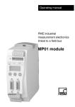
Operating manual
PME industrial
measurement
electronics linked
to a field bus
MP55 module
A0563-5.6 en
3
PME-MP55
Contents
Page
Safety instructions . . . . . . . . . . . . . . . . . . . . . . . . . . . . . . . . . . . . . . . . . . . . .
4
1 Introduction . . . . . . . . . . . . . . . . . . . . . . . . . . . . . . . . . . . . . . . . . . . . . . . . .
1.1 List of components and accessories supplied . . . . . . . . . . . . . . . .
1.2 Introduction . . . . . . . . . . . . . . . . . . . . . . . . . . . . . . . . . . . . . . . . . . . . . .
7
7
7
2 Choose amplifier settings with the aid of DIP switches . . . . . . . . .
8
3 Fitting/removing the MP55 . . . . . . . . . . . . . . . . . . . . . . . . . . . . . . . . . . .
3.1 Linking several modules . . . . . . . . . . . . . . . . . . . . . . . . . . . . . . . . . . .
12
13
4 Connections . . . . . . . . . . . . . . . . . . . . . . . . . . . . . . . . . . . . . . . . . . . . . . . .
4.1 Functional overview of the MP55 . . . . . . . . . . . . . . . . . . . . . . . . . . .
4.2 Supply voltage and remote contact I/Os . . . . . . . . . . . . . . . . . . . . .
4.2.1 External supply voltage for the control I/Os . . . . . . . . . . . . . .
14
14
15
16
4.3 Transducers . . . . . . . . . . . . . . . . . . . . . . . . . . . . . . . . . . . . . . . . . . . . .
4.4 CAN-interface . . . . . . . . . . . . . . . . . . . . . . . . . . . . . . . . . . . . . . . . . . . .
4.5 Synchronisation . . . . . . . . . . . . . . . . . . . . . . . . . . . . . . . . . . . . . . . . . .
17
19
20
5 Setting up and operation (MP55) . . . . . . . . . . . . . . . . . . . . . . . . . . . . . .
5.1 Operating principles . . . . . . . . . . . . . . . . . . . . . . . . . . . . . . . . . . . . . .
5.2 Commissioning . . . . . . . . . . . . . . . . . . . . . . . . . . . . . . . . . . . . . . . . . . .
5.3 Overview of all groups and parameters . . . . . . . . . . . . . . . . . . . . . .
5.3.1 Set up all parameters . . . . . . . . . . . . . . . . . . . . . . . . . . . . . . . .
21
21
24
25
26
6 Declaring the significant parameters . . . . . . . . . . . . . . . . . . . . . . . . . .
30
7 CAN interface description . . . . . . . . . . . . . . . . . . . . . . . . . . . . . . . . . . . .
7.1 Introduction . . . . . . . . . . . . . . . . . . . . . . . . . . . . . . . . . . . . . . . . . . . . . .
7.2 Cyclical data transmission . . . . . . . . . . . . . . . . . . . . . . . . . . . . . . . . .
7.3 Parameter assignment . . . . . . . . . . . . . . . . . . . . . . . . . . . . . . . . . . . .
7.4 Object directory: communications profile section
as defined in CANopen (CiA-DS301) . . . . . . . . . . . . . . . . . . . . . . . .
7.5 Object directory: manufacturer-specific objects . . . . . . . . . . . . . . .
7.6 Manufacturer-specific objects in FLOAT data format . . . . . . . . . . .
7.7 Examples . . . . . . . . . . . . . . . . . . . . . . . . . . . . . . . . . . . . . . . . . . . . . . .
38
38
38
39
41
44
53
55
8 Error messages/operating status (LED) . . . . . . . . . . . . . . . . . . . . . . .
57
9 Specifications . . . . . . . . . . . . . . . . . . . . . . . . . . . . . . . . . . . . . . . . . . . . . . .
60
10 Keyword index . . . . . . . . . . . . . . . . . . . . . . . . . . . . . . . . . . . . . . . . . . . . . .
63
A0563-5.6 en
HBM
4
PME-MP55
Safety instructions
Use in accordance with the regulations
The MP55 module and its connected transducers are to be used exclusively
for measurement tasks and directly related control tasks. Use for any additional purpose shall be deemed to be not in accordance with the regulations.
In the interests of safety, the instrument should only be operated as described
in the User Manual. It is also essential to observe the appropriate legal and
safety regulations for the application concerned during use. The same applies
to the use of accessories.
The device must not be connected directly to the mains supply. The
maximum permissible supply voltage is 18...30 V.
General dangers of failing to follow the safety instructions
The MP55 module corresponds to the state of the art and is safe to operate.
The instrument can give rise to further dangers if it is inappropriately installed
and operated by untrained personnel.
Everyone involved with the installation, commissioning, maintenance or repair
of the instrument must have read and understood the User Manual and in particular the technical safety instructions.
Conditions on site
Protect the device from direct contact with water (IP20).
Maintenance and cleaning
The MP55 module is maintenance-free. Please note the following points when
cleaning the housing:
- Before cleaning, disconnect the devices from the power supply.
- Clean the housing with a soft, slightly damp (not wet!) cloth. You should
never use solvent, since this could damage the labelling on the front panel
and the display.
- When cleaning, ensure that no liquid gets into the device or connections.
HBM
A0563-5.5 en
5
PME-MP55
Residual dangers
The scope of supply and list of components provided with the MP55 cover
only part of the scope of measurement technology. In addition, equipment
planners, installers and operators should plan, implement and respond to the
safety engineering considerations of measurement technology in such a way
as to minimise residual dangers. Prevailing regulations must be complied with
at all times. There must be reference to the residual dangers connected with
measurement technology.
Any risk of residual dangers when working with the MP55 is pointed out in this
introduction by means of the following symbols:
Symbol:
WARNING
Meaning: Dangerous situation
Warns of a potentially dangerous situation in which failure to comply with
safety requirements can lead to death or serious physical injury.
CAUTION
Symbol:
Meaning: Possible dangerous situation
Warns of a possibly dangerous situation in which failure to comply with safety
requirements can cause damage to property or lead to some form of physical
injury.
Symbol:
NOTE
Means that important information about the product or its handling is being
given.
Symbol:
Meaning: CE mark
The CE mark enables the manufacturer to guarantee that the product complies with the requirements of the relevant EC directives (the declaration of
conformity is available at http://www.hbm.com/support/dokumentation).
A0563-5.5 en
HBM
6
PME-MP55
Working safely
Error messages should only be acknowledged if the cause of the error is removed and no further danger exists.
The instrument complies with the safety requirements of DIN EN 61010,
Part 1 (VDE 0411, Part 1).
To ensure adequate immunity from interference, use only Greenline shielded
ducting (place the shield of the transducer cable onto the connector housing).
The MP55 module must be operated with an extra-low safe voltage (supply
voltage 18 to 30 V DC).
Conversions and modifications
The MP55 module must not be modified from the design or safety engineering
point of view except with our express agreement. Any modification shall exclude all liability on our part for any damage resulting therefrom.
In particular, any repair or soldering work on motherboards is prohibited.
When exchanging any modules, only original HBM parts must be used.
Qualified personnel
This instrument is only to be installed and used by qualified personnel strictly
in accordance with the technical data and with the safety rules and regulations
which follow. It is also essential to comply with the appropriate legal and
safety regulations for the application concerned during use. The same applies
to the use of accessories.
Qualified personnel means persons entrusted with the installation, assembly,
commissioning and operation of the product who possess the appropriate
qualifications for their function.
Maintenance and repair work on an open device with the power on must only
be carried out by trained personnel who are aware of the dangers involved.
HBM
A0563-5.5 en
7
PME-MP55
1
Introduction
1.1 List of components and accessories supplied
List of components supplied:
D 1 MP55 module
D 3 x 6-pin terminal plugs, coded
Order No.: 3.3312-0251 (terminal plug 3);
3.3312-0252 (terminal plug 4); 3.3312-0250 (terminal plug 1)
D 10-pin ribbon cable jack-connector
D 1 User Manual for the MP55 module
Accessories:
D 15-pin Sub-D connector for transducer, Order No.: 3.3312-0182
D Standard ribbon cable, 10pin, 1.27 mm pitch
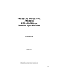
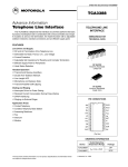
1.2 Introduction
The MP55 module from the PME product line is a carrier-frequency amplifier,
and is ideal for connecting the widest possible technological varieties of force,
pressure, torque and displacement transducers as well as load cells. The
MP55 module is set up, and its parameters are assigned, using either the keyboard and display or the PME Assistent. The PME Assistent provides an easy
operator interface under MS-Windows and this is used for assigning parameters to modules (as described in the ”PME Assistant” online help).
Carrier-frequency
transducer excitation
A
D
µP
DC
D
A
Smart signal conditioning, e.g. limit value switch
MP55
Fig. 1.1:
A0563-5.5 en
Keyboard & display
DC
24 V Supply voltage
Analogue output
Control I/Os
CANopen interface
Block diagram of the MP55 module
HBM
8
PME-MP55
2
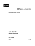
Choose amplifier settings with the aid of DIP switches
NOTE
The DIP switches must be set up/changed before the PME is fitted.
Various settings are defined with DIP switches and can be read out via the
display (see chapter 5.3). These are the settings for
bridge excitation voltage, effective range, bridge type, analogue output,
master/slave, terminating bus impedance, edge steepness
To set up the DIP switches proceed as shown in Fig. 2.1.
1
2
Unscrew the
cover
S10
S11
S12
Fig. 2.1:
HBM
S1/S2
S5
Open the housing; position of the DIP switches
A0563-5.5 en
9
PME-MP55
Factory settings:
ON
S2
ON
Lower
board:
S10, S11 and
S12 and S5
Upper
board:
S1 and S2
S1
1 2 3 4 5 6 1 2 3 45 6
ON
ON
S5
3
2
1
S12
1
2
3
4
5
6
ON
S11
ON
S10
1
2
3
4
5
6
1
2
3
4
5
6
ON
Analogue output
1 2 3
ON
S10
1 2 3456
Master/
Slave
ON
S11
12 34 56
Analogue
output
S12
1 23456
Bridge excitation
voltage
Input
range
A0563-5.5 en
ON
Bridge
type
ON
S2
ON
S1
1 2 34 5 6 123 4 56
Bridge ex- Bridge
citation vol- type
tage
Input
WARNING
range
Switch positions
must not be changed!
Amplifier type
HBM
10
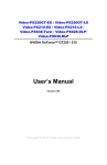
PME-MP55
Factory setting:
S2 S1
S11
S12
S5
Bridge type1)
ON
Input range*) 2)
ON
ON
S1
Full bridge
1 23456
S12
ON
1 23456
S12
S1
1 23456
1 23456
ON
S12
S1
1 23456
S1
1 23456
1 23456
ON
500 mV/V
Switch pos. III
S11
1 23456
ON
ON
LVDT
ON
50 mV/V
Switch pos. II
S11
1 23456
ON
ON
Half bridge
S1
3 mV/V
Switch pos. I
1 23456
ON
S1
1 23456
S11
1 23456
See Tab. 1.1 on the opposite page
Bridge excitation voltage3)
ON
S11
1 23456
1 23456
ON
ON
2.5 V
ON
ON
S2
5V
Analogue output4)
S2
123 4 5 6
ON
"10 V
S11
1 23456
123
S11
"20 mA
S11
ON
1 23456
mA
ON
1234 56
Fig. 2.2:
1)
2)
3)
4)
*)
ON
S2
1V
4...20 mA
S11
1 23456
S5
ON
1 23456
ON
V
S11
S5
123
1 23456
Setting up an amplifier
Check this in the display under the TRANSDUCER group, parameter ”Trans.type”; see page 25
Check this in the display under the TRANSDUCER group, parameter ”Input”; see page 25
Check this in the display under the TRANSDUCER group, parameter ”Excitation”; see page 25
Check this in the display under the ANALOG OUTPUT group, parameter ”ModeUa”, see page 25
mV/V values by reference to 5 VUB (see table Tab. 1.1 on the following page)
HBM
A0563-5.5 en
11
PME-MP55
ON
S10
Master
Master/Slave
1 23456
S10
ON
Slave
S10
1 23456
Fig. 2.3:
Setting up an amplifier (Continued)
Terminating bus resistor
S14
Toggle switch for termination resistor
(see page 19)
ON
Fig. 2.4:
OFF
Toggle switch for termination resistor
Bridge excitation voltage [V]
Input range [mV/V]
Switch position I
Switch position II
Switch position III
5
3
50
500
2.5
6
100
1000
1
15
250
2500
Tab. 1.1: Input ranges for different bridge excitation voltages
Transducer type and rated data
Bridge type
Bridge excitation
voltage
Input range
Strain gauge force transducer
2 mV/V=20 kN
Full bridge
5V
3 mV/V
Inductive displacement transducer
80 mV/V
Half bridge
2.5 V
100 mV/V
Inductive displacem. trans. 10 mV/V
Half bridge
1V
15 mV/V
Piezoresistive transducer 400 mV/V
Half bridge
1V
250 mV/V
2.5 V
1000 mV/V
Potentiometric transducer 1000 mV/V Half bridge
Tab. 1.2: Useful options
A0563-5.5 en
HBM
12
3
PME-MP55
Fitting/removing the MP55
Fig. 3.1:
Fitting to a support rail
Fig. 3.2:
Removal
CAUTION
The support rail must be on protection circuit potential
HBM
.
A0563-5.5 en
13
PME-MP55
3.1 Linking several modules
Ribbon cable jack-connector
Further devices are interconnected
via this connector.
1st
Colour coding
on pin 1
2nd
3rd
58mm
Recommended distance from the ribbon cable jack-connector
Fig. 4.1:
Connecting ribbon cable
Several MP55 modules can be connected via one ribbon cable. This cable
serves as the local link for supply voltage and synchronisation between modules. No more than eight modules should be interconnected over one ribbon
cable.
A0563-5.5 en
HBM
14
4
PME-MP55
Connections
Warning
Comply with the safety instructions before putting the instrument into
service.
4.1 Functional overview of the MP55
Local link for CAN-bus, supply voltage and synchronisation between modules,
Terminating bus resistor
Terminal plug 1:
Power supply and CAN-bus,
synchronisation
LED
Terminal plug 2: (same pin
assignment as terminal plug 1)
CAN adapter for PC/laptop
connection, assigning parameters
via CAN-bus
2-line LCD display
Touch-sensitive
control keys
Transducer connection (15-pin sub-D
connector) including transducer
excitation
Terminal plug 3:
Potential-separated control inputs
(24 V-level), analogue output
Terminal plug 4:
Potential-separated control outputs
(24 V-level), external power supply for
control inputs
HBM
A0563-5.5 en
15
PME-MP55
4.2 Supply voltage and remote contact I/Os
Four removable terminal plugs are available for connections.
Connecting the power
supply:
Warning
The MP55 module must be connected to an external
18-30 V supply voltage (24 V nominal).
D Twist the power supply conductors and fit them with
sleeves.
D Screw the conductors to terminal plug 1.
D Insert the terminal plug into the uppermost jack.
D Switch on power supply.
CAN
0V
24 V
L
Terminal plug 2
H
SYN
Labeling
Terminal plug 1
Terminal plug 3
Terminal plug 4
Labeling
Labeling
0V
AnalogueOUT
24 V
OUT1
IN3
"10 V
IN2
"20 mA
4...20 mA IN1
IN = digital input
IN4
OUT4
OUT2
OUT3
OUT = digital output
More information on I/Os can be found in chapter 6, page 35.
CAUTION In the event of a power failure to the MP55 module, all control
outputs are set to 0 V.
Fig. 4.2:
Pin assignment for terminal plugs
The 4 terminal plugs are coded so that they can be inserted in the 4 jacks
without any confusion. Jacks are fitted with coded lateral guides and terminal
plugs are fitted with coded pins.
A0563-5.5 en
HBM
16
PME-MP55
4.2.1 External supply voltage for the control I/Os
Example: PLC connection
MP55 module
OUT3
PLC
max. 0.5 A
Relay
max. 0.5 A
OUT1
24 V*
0 V*
24 V
0 V*
Terminal plug 4
Fig. 4.3:
Connection to a PLC
The controlinputs are available on terminal plug 3, the controloutputs are
available on terminal plug 4, and they are all galvanically isolated from the internal supply voltage (see also chapter 6, ”Declaring the significant parameters” page 30).
*) The control-outputs must be supplied with an external voltage (ground
and 24 V).
HBM
A0563-5.5 en
17
PME-MP55
4.3 Transducers
The following transducer types can be connected to the MP55 module:
Transducer
connection jack
8
15
9
1
Strain gauge and inductive full
bridges, piezoresistive transducers
wh
bk
re
bu
gn
gy
ye
Strain gauge and inductive half
bridges
wh
8
Measuring signal (+)
Bridge excitation
voltage (-)
Measuring signal (-)
Bridge excitation
voltage (+)
5
15
6
13
Sensor circuit (-)
12
Cable shielding
Hsg.
Measuring
signal (+)
Bridge excitation
voltage (-)
Bridge excitation
voltage (+)
2
1
Wiring colours:
Fig. 4.4:
A0563-5.5 en
Bridge excitation
voltage (+)
Sensor circuit (+)
13
Sensor circuit (-)
12
ye
Cable shielding
5
6
Hsg.
LVDT transducers
8
5
Measuring signal
(+)
Bridge excitation
voltage (-)
8
6
Sensor circuit (+)
13
Bridge excitation
voltage (+)
Measuring signal
(-)
Cable shielding
Sensor circuit (+)
Sensor circuit (-)
12
Sensor circuit (-)
Cable shielding
3
bu
gy
Potentiometric transducers
8
Bridge excitation
voltage (-)
gn
Sensor circuit (+)
Measuring signal (+)
bk
6
Hsg.
5
15
Hsg.
13
12
wh= white; bk= black; bu= blue; re= red; ye= yellow; gn= green;
gy= grey
Connecting various transducers
HBM
18
PME-MP55
When installing a transducer with a four-wire connection, you must connect
the sensor lines with the corresponding bridge excitation line (Pin 5 with Pin
12, Pin 6 with Pin 13) 1).
Four-wire connection:
Full bridge
wh
bk
re
bu
8
5
Four-wire connection:
Half bridge
wh
5
15
6
13
15
bu
Hsg.
6
gn
13
gy
12
ye
8
bk
ye
12
Hsg.
Feedback bridges for four-wire connection
Wiring colours:
Fig. 4.5:
wh= white; bk= black; bu= blue; re= red; ye= yellow; gn= green; gy= grey
Four-wire transducer connection
NOTE
Use standard HBM cable for the transducer connection. When using
other shielded, low-capacitance measuring cable, connect the transducer cable shielding to the connector housing in accordance with the
HBM Greenline concept (publication S1578). This ensures EMC protection.
1)
For cable lengths in excess of 50 m, one resistor with half the value of the bridge resistance (RB/2) must
be switched on at the transducer in place of each of the feedback bridges. If the transducers are calibrated in six-core circuit, the resistors must be switched on directly in the sensor circuit.
HBM
A0563-5.5 en
19
PME-MP55
4.4 CAN-interface
The CAN-bus is connected via terminal plug 1. A maximum of 32 CAN users
can be connected to a bus segment (in accordance with the CANopen specification). The CAN-bus needs a terminating impedance of 120 Ω in the first and
last bus users. The bus line can have a maximum of two terminating resistors.
The MP55 module has a built-in terminating resistor which is enabled by
toggle switch S14 (see page 11).
Low
High
1st device
Fig. 4.6:
Connecting the CAN interface
CAN-High
CAN-Low
CAN connection
in accordance
with Fig. 4.6
First device in
the bus line
connect the terminating
resistor here (toggle
Do not connect the terminaswitch)
ting resistor
Fig. 4.7:
Last device in
the bus line
connect the terminating
resistor here (toggle
switch)
CAN-bus operation with several modules (maximum 32 in accordance
with standard)
NOTE
If the first or last device in the bus line is not a PME module, one 120 W
resistor must be connected for each of these outside devices.
A0563-5.5 en
HBM
20
PME-MP55
4.5 Synchronisation
Synchronisation is advisable when
D the transducer cables are connected in parallel to several devices
D unshielded channels lie close together
Synchronisation prevents carrier-frequency differences giving rise to beat interference.
S10
S10
ON
ON
S10
Slave
Master
1 2 3 4 56
Fig. 4.8:
1 23 4 5 6
Setting up master/slave
To synchronise several instruments, set up one of them as Master. Set up all
the other instruments as Slaves.
Synchronisation between modules should always be carried out via the ribbon
cable- even when you are not working with CAN-bus.
HBM
A0563-5.5 en
21
PME-MP55
5
Setting up and operation (MP55)
5.1 Operating principles
Display in measuring mode:
-18.0024
kg
Status field
↑
↓
Value
unit
The status field flashes if the parameter value can be edited
The keys
+
-
are pressure-sensitive:
Hold key down - the values scroll (the harder you press, the faster they scroll)
Press key briefly - go to next value
Function of the
buttons:
SET
1. Switch from measuring mode to
input mode
2. Choose the first parameter within
the group.
3. Confirm input
4. Return to measurement range
(press for 2 sec)
A0563-5.5 en
-
+
Select
parameter/group
+
-
HBM
22
PME-MP55
Measuring mode
Password status
inactive (factory setting):
Password status
enabled
SET 2 sec
SET 2 sec
PASSWORD
DIALOGUE
Set-up mode
Input password:
SET
Password
SET
Input mode
+
↑
↓
Input required password
(factory setting 0)
-
Confirm
SET
Example:
Change
settings:
+
SET
+
Select
group
Input numerical
value
Select table
value
TRANSDUCER
CONDITIONING
Select first
parameter
unit
Nom. mV/V
0.000
Select required parameters
SET
+
SET
Back to
measuring
mode:
kN
Filter
_ _ Hz
↑
↓
Input numerical value or
Choose table value
2.000
0.5 Hz
Confirm
SET 2 sec PME asks: Save ?
2x
SET
saves
directly
HBM
Go to input mode
>0<
YES
NO
SET
+/-
SET
Save ?
No
A0563-5.5 en
23
PME-MP55
During measurement you can press
play:
1. Display mode
2. The status of input and output
3. Error types (ERROR)
+
- to look at the following in the dis-
-
The status field also displays the symbols
Status field
-18.0024
kg
!
,
and
.
Value
unit
Symbol in status field
Display mode
No character
Gross signal
>T<
Net signal
Maximum peak value signal
Minimum peak value signal
Peak/peak signal
+
-
mV/V
Input signal
V or mA
Analogue output signal
set,
Outp
Inpt
not set
Status of input and output
e.g. StoreMax
Error messages
During measurement the character ! warns of an error
in the module.
Current errors are automatically displayed one after
another in display mode ”ERROR” (accessible
through + ).*)
Status field
!
Error occurred
Standstill status occurred
Shunt resistor on
*) see chapter 8 ”Error messages”, page 57
A0563-5.5 en
HBM
24
PME-MP55
5.2 Commissioning
D Set up the DIP switches in accordance with chapter 2 (pages 10 and 11).
Example:
Transducer type and rated data
Bridge type
Bridge excitation
voltage
Input range
Strain gauge force transducer
2 mV/V=20 kN
Full bridge
5V
3 mV/V
Inductive displacement transducer 80 mV/V
Half bridge
2.5 V
100 mV/V
Inductive displacement transducer 10 mV/V
Half bridge
1V
15 mV/V
Piezoresistive transducer 400 mV/V
Half bridge
1V
250 mV/V
Potentiometric transducer 1000 mV/V
Half bridge
2.5 V
1000 mV/V
D Connect the power supply cable and the transducer to the module, as
described in chapters 4.2 and 4.3.
CAUTION
Be sure to follow the safety instructions!
D Switch on the power supply.
The instrument carries out a function test (approx. 15 sec) and if
functioning correctly, switches to measuring mode. During the function
test, the remote contacts stay at 0 V.
NOTE
If the error message HardwOvf is displayed at this point, please refer to
chapter 8 ”Error messages” for more details.
A green LED also tells you whether the MP55 is ready to begin measuring.
If the LED shows yellow or red, please refer to chapter 8 ”Error messages” for
more details.
NOTE
When connecting transducers in parallel, please take into account the
resulting total resistance. If required, reduce the excitation voltage.
HBM
A0563-5.5 en
+
SET
SET
25
5.3 Overview of all groups and parameters
Groups
-
DIALOG
DATA SET
DISPLAY
TRANSDUCER
TRANSD.CALIBRAT
CONDITIONING
ANALOGOUTPUT
LIMIT VAL.
1...4
PEAK STORE
IN/OUT
CAN-BUS
ADDITION FUNCTION
Password
Recall ?
DecPoint
Unit
P1Meas.?
>0< kN1)
SourceUa
Operatn.
Operatn.
Output1
Baudrate
AmplType
PassStat
Save ?
Step
Transd.Type
P1 mV/V
>0<set ?
Mode UA
Source
InputMin
ModeOut1
Address
PrgVers
>0<save
kN1)
SwtchDir
InputMax
Output2
Profil
>0<Rf kN1)
ModeOut2
Output
MotionDsp
Output3
OutR. ms
MTime ms
ModeOut3
PDO-Frmt
MAmp kN1)
MAINGR
HW Synchr
Language
Up
I.DataS
InputRng
P2Meas.?
>T< kN1)
Zero V
Value kN1)
-
I.Displ.
ZeromV/V
P2 mV/V
>T<set?
EndV kN1)
Hyst kN1)
Down
I.Transd
Zero kN1)
P2 kN1)
>T<save
EndV V
On Del ms
I.Calibr
Nom.mV/V
MAINGR
filtre
MAINGR
Off Del ms
Output4
I.Condit
NVal kN1)
FiltChar
MAINGR
ModeOut4
Keyboard
I.Analog
Zero.Adj
MAINGR
Zeroing
SNo prior version
I.LimVal
NomV.Adj
Tare
HW-Vers.
I.PStore
Shunt
PkMomMax
MAINGR
I.I/O
ShuntPol
PkHldMax
I.CAN
MAINGR
PkMomMin
Overview of parameters
+
MAINGR
MAINGR
Excitatn
P1
kN1)
Zero
ClearPkV
kN/s1)
MAINGR
I.AddFnc
PkHldMin
MAINGR
ParaCo1
ParaCo2
InpFunc
MAINGR
Preset with DIP switches , MAINGRP with
1)
Depending on the unit chosen
SET
back to group
A0563-5.6 en HBM
5.3.1 Set up all parameters
2sec
Meas. value
PassStat
active
SET
Yes
PASSWORD
Groups
No
+
+
DIALOG
SET
↑
↓____
+/-
Password
+
DATA SET
-
SET
SET
Password
A0563-5.6 en HBM
SET
SET
↑ ____
↓
+/-
Recall ?
PassStat
SET
Language
SET
↑
↓ active
inactiv
Deutsch
↑ English
↓
Francais
SET
↑
↓ DataS1
DataS2
DecPoint
+/-
DataS3
DataS4
FactSet
No
+
-
I.Displ.
Save ?
SET
back
MAINGRP
SET
↑
↓ DataS1
DataS2
DataS3
DataS4
No
SET
back
MAINGRP
SET
I.Calibr
I.Condit
SET
I.Analog
↑ free
↓
locked
+
-
I.I/O
Confirm input:
+/- =
+/-
+
or
SET
press
-
Back to measuring mode:
Note:
If a group cannot be selected, check under DIALOG to see
whether the group is enabled.
SET
2sec
26
back
MAINGRP
0005
0010
0020
0050
0100
0200
0500
1000
Flashes if the parameter
value can be edited
↑
↓
I.AddFnc
↑ 0001
↓
0002
Select parameter
I.PStore
I.CAN
+/-
Parameter values
+/-
I.LimVal
SET
.000
.00
.0
.
Step
+/-
I.Transd
-
.00000
↑ .0000
↓
-
+/-
+
SET
+
+/-
I.DataS
-
SET
Define
password
Input
password
Continue
with DIALOG
Display
-
Transducer
+
TRANSDUCER
+
-
TRANSD.-CALIBRAT
SET
SET
BrdgeTyp
FullBrdg
+/-
Preset with DIP switches
S1 and S12
SET
fixed
w.switches
Preset with DIP switches
S2 and S11
Excitatn
5.0V
SET
fixed
w.switches
Preset with DIP switches
S1 and S11
InputRng
3mV/V
ZeromV/V
SET
SET
fixed
w.switches
↑ 0.0000
↓
+/-
-
Zero kN1)
Nom.mV/V
NVal
kN1)
Shunt
SET
SET
SET
SET
↑ 0.00
↓
↑
↓ 2.0000
↑
↓ 10.00
Off
↑
↓ On
+/-
+/-
+/-
kg ↑
↓
T
kT
TON
lb
oz
N
kN
Bar
mBar
Pa
Pas
hPas
kPas
psi
µm
mm
cm
m
inch
Nm
kNm
FTLB
INLB
µm/m
M/S
M/SS
p/0
p/00
ppm
S
MP
MN
g
SET
nein
↑ no
↓
ja
yes
P1 mV/V
SET
SET
SET
↑+Unbala
↓
-Unbala
>0<
↑ 0.0000
↓
kN1)
SET
↑ no
↓
yes
SET
kN1)
>0<save
+/-
↑ 0.00
↓
SET
↑
↓ 0.0000
>T<set?
SET
no
↑
↓ yes
SET
↑
↓ 0.00
-
StoreMax
StoreMin
Store PP
CAN
+/-
+/-
+/-
Mode Ua
10V
SET
fixed
w.switches
Zero kN1)
SET
↑ 0.00
↓
+/-
SET
↑
↓ 0.00
+/-
SET
↑
↓ 10.00
+/-
SET
↑
↓ 10.00
+/-
+
>T<
P2Meas.?
SET
SET
>T<save
kN1)
SET
filtre
↑
↓ save
volatil
SET
+/-
Zero V
SET
EndV kN1)
+/-
↑
↓ 0.0000
FiltChar
+/-
SET
↑ Bessel
↓
Butterw
EndV V
↑ 0.05 Hz
↓
SET
back
MAINGRP
+/-
SET
-
↑
↓ 0.0000
+/-
P2
+/-
+
+/-
P2 mV/V
kN1)
nein
↑
↓ no
ja
yes
-
1)
↑
↓ GrosValu
NetValue
SET
+/-
↑ save
↓
volatil
SET
SourceUa
+/-
Preset with DIP switches
S11 and S5
+/-
+/-
back
MAINGRP
-
SET
>0<set ?
+/-
+
ShuntPol
-
LimVal.1
+
ANALOG OUTPUT
SET
P1Meas.?
P1
+
CONDITIONING
SET
Unit
+
27
Groups
Display
back
MAINGRP
Depending on the unit chosen
+/-
0.1 Hz
0.2 Hz
0.5 Hz
1 Hz
2 Hz
5 Hz
10 Hz
20 Hz
50 Hz
100 Hz
200 Hz
500 Hz
SET
back
MAINGRP
A0563-5.6 en HBM
Groups
Analogue output
+
LIMIT VAL.1
-
+
LIMIT VAL.2...4
A0563-5.6 en HBM
+
PEAK STORE
-
IN/OUT
-
SET
SET
Operatn.
Source
SET
SET
↑ On
↓
Off
+/-
GrosValu
↑
↓ NetValue
StoreMax
StoreMin
Store PP
SwtchDir
SET
↑
↓ Higher
Lower
SET
↑
↓ On
Off
InputMin
SET
↑ GrosValu
↓
NetValue
InputMax
SET
+/-
+
+/-
-
LimVal1
↑
↓ LimVal2
SET
Operatn.
+/-
As
appropriate
for 1...4
+/-
↑ GrosValu
↓
NetValue
CAN-Bus
+
Output1
SET
ModeOut1
SET
Zeroing
SET
LimVal3
LimVal4
Motion
Error
inactiv
Act. On
↑
↓ Act.Off
+/-
+/-
+/-
Tare
Value kN1)
+
SET
↑
↓ 0.00
+/-
ClearPkV
-
Hyst
kN1)
SET
↑
↓ 0.00
Off Delms
SET
SET
↑
↓ 0000.0
↑ 0000.0
↓
No
↑
↓ Yes
+
+/-
PkMomMax
+/-
↑ Input 1
↓
Input 2
-
kN/s
On Del ms
SET
SET
↑
↓ 0.00000
PkHldMax
+/-
+/-
+/-
Input 3
Input 4
NoInput
PkMomMin
SET
+/-
back
MAINGRP
PkHldMin
ParaCo1
SET
back
MAINGRP
ParaCo2
InpFunc
1)
Depending on the unit chosen
SET
back
MAINGRP
↑ free
↓
locked
+/-
28
The same applies to limit values 2 to 4
SET
29
Groups
In/Out
+
CAN-Bus
-
SET
Baudrate
10 kB
↑
↓ 20 kB
SET
+/-
50 kB
125 kB
250 kB
500 kB
800 kB
1000 kB
Address
SET
↑
↓
SET
↑
↓ no Prof
000
+
ADDITIONFUNCTION
-
MEAS MODE
SET
SET
AmplType
Save ?
SET
↑
↓ Yes
No
+/-
PrgVers
>0< Rf kN1)
+/-
SET
↑
↓ 0.00000
+/-
Meas. value
+
-
Profil
Output
+/-
StoreMax
StoreMin
Store PP
GrosDsp
NetDsp
SET
MTime ms
SET
+
-
↑ GrosValu
↓
NetValue
SET
MotionDsp
MAmp kN1)
+/-
HW Synchr
Slave
OutpR ms
PDO-Frmt
SET
↑
↓
SET
000
↑ float
↓
integer
SET
SET
SET
+/-
Keyboard
+/-
SET
↑ Off
↓
On
+/-
↑ 0000.0
↓
↑
↓ 0000.0
+/-
+/-
fixed
w.switches
↑ slow
↓
fast
medium
Preset with
DIP switch S10
+/-
SNo
HW-Vers.
back
MAINGRP
1)
Depending on the unit chosen
SET
back
MAINGRP
A0563-5.6 en HBM
30
6
PME-MP55
Declaring the significant parameters
Group
Parameter
Meaning
DIALOG
Password
Define password (modify), 0000...9999
(Factory preset password: 0000)
PassStat
Define password status:
active=password must be input;
inactive=PME can be operated without entering a password
I.DataS to
I.AddFnc
Access to group via keyboard enabled or disabled.
Recall ?
You can load either the factory settings or one of the four
parameter sets that have been stored.
Save ?
To protect all the instrument set-ups from power failure, they
can be stored in four parameter sets. Whenever you change
from set-up mode to measuring mode you are asked whether
you want the changes to be stored or not. The data will be
permanently saved if you confirm the security prompt with
”Yes” when you exit from set-up mode.
DATA SET
TRANSDUCER
ZeromV/V Setting up in accordance with transducer characteristics
Zero kN1) Physic. unit
Transducer characteristics: Nominal value 10 kN;
Nom.mV/V
Rated sensitivity 2 mV/V
NVal kN1)
Nom.kN
( 10 kN for 2 mV/V)
Zero
kN 0
Zero mV/V
Nom.mV/V (
1)
mV/V
2 mV/V)
Depending on the unit chosen
HBM
A0563-5.6 en
31
PME-MP55
Group
Parameter
TRANSDUCER
Meaning
Information on scaling
Input characteristics:
The range of values for scale factors is limited. Scaling is
dependent on the chosen resolution. In the case of set-ups
that lead to overshooting the respective limits, ”Scaling error”
is reported (see page 58).
Maximum display resolution: 999 999 digits at 6.67 % of the input range
Minimum display resolution: 10 Digits at 100 % of the
input range
TRANSD.CALIBRAT
Shunt
ShuntPol
Defines the polarity of the shunt resistor (positive or negative
effect). The mismatch amounts to approx. 1 mV/V at a
transducer sensitivity of 2 mV/V and a bridge resistance of
350 Ω. Accuracy approx. 4 %.
P1Meas.?
P1 mV/V
P1 kN1)
Assigning the signals issued by the transducer at a defined load
Physic.
Unit
p2
Example: A calibration weight of 10 kg is
used to calibrate a 4 kg-load cell.
1. Relieve transducer
P1Meas.? Yes
p1
0,0457 mV/V
P1
Enter 0 kg
(physic. Unit is assigned)
mV/V
2. Load transducer with 4kg
P2Meas.? Yes
P2
7,873 mV/V
Enter 4 kg
Note: If the zero point is modified, P1 and P2 will be discarded.
CONDITIONING
Difference between taring and zeroing: zero balance
(>0 kN<) affects both gross and net values. Taring (>T<) affects only the net value.
Here is an example to illustrate the difference between zero
balancing and taring:
Platform
Container
ÇÇÇÇÇÇÇÇÇÇÇ
Steps in the
weighing procedure
1)
Action
Display
Gross
Net
Attach platform
(35 kg)
> 0<
Input 35 kg
before 35 kg
after 0 kg
before 35 kg
after 0 kg
Attach container
(8 kg)
> T<
Input 8 kg
before 8 kg
after 8 kg
before 8 kg
after 0 kg
Depending on the unit chosen
A0563-5.6 en
HBM
32
PME-MP55
Group
Parameter
Meaning
CONDITIONING
>0<kN1)
Enter zero value. Zeroing effects both, the gross value and
the net value.
>0< set ?
Trigger zero balance; set current measured value (physical
unit) to zero
>0< save
Each time there is a zeroing procedure the zero value is
adopted into the EEPROM (service life 100.000 cycles)
>T< kN1)
Input tare value. Taring affects the net value.
>T< set ?
Trigger taring; net value becomes 0
>T<save
Save tare value immediately after taring
Filter
FiltChar
0.05 Hz
0.1 Hz
0.2 Hz
0.5 Hz
1 Hz
2 Hz
5 Hz
10 Hz
20 Hz
50 Hz
100 Hz
200 Hz
500 Hz
Step response
The diagram shows a linear amplitude response which falls away steeply above the
cut-off frequency. There is an overshoot of
approx. 10 %.
Time
Best frequency response
(Butterworth)
Step response
The diagram shows a step response with very
little (<1 %) or no overshoot. The amplitude
response falls away less steeply.
Time
Best course over time
(Bessel)
1)
Depending on the unit chosen
HBM
A0563-5.6 en
33
PME-MP55
Group
Parameter
Meaning
ANALOGOUTPUT
SourceUa
The gross or net value and the peak value can be chosen as
the source for the analogue signal.
Mode Ua
Use DIP switches S11 and S5 to define the analogue output
signal mode. The following options are possible:
"10 V, "20 mA, 4...20 mA
V
Zero kN1)
Zero V
EndV kN1)
EndV V
EndV V
Zero V
0
Zero
kN
EndV
kN
Physical unit
Information on scaling
Output characteristics:
The scale factor for the analogue output is derived from the
input and output characteristics. If the span that has been set
up corresponds to the measurement range in mV/V, the
minimum output voltage that can be set up is 0.17 V. If the
settings cause the respective limits to be exceeded,
”Analogue scaling error” is reported (see page 58).
Scale range min. for analogue output: 0.17 V at 100 % of amplifier input
range
Scale range max. for analogue output: 10 V at 3.67 % of amplifier input
range
1)
Depending on the unit chosen
A0563-5.6 en
HBM
34
PME-MP55
Group
Parameter
Meaning
LIMIT VAL.
1...4
Source
You can choose from the following as the source for the limit
value signal: Gross, Net, Peak value Max/Min / Peak-to-peak
SwtchDir
Value
Hyst
Functions and parameters of limit values
Limit1, ON
Value
Over limit
Below limit
Hyst
OFF
OFF
Hyst
Value
Limit2, ON
24 V
0V
Limit1 ON
24 V
0V
Limit2 ON
PEAK
STORE*)
On Del ms
Starting delay; in the event of exceeding a limit value level,
the change only takes effect after the delay time (On Del) at
the output.
Off Del
ms
Cut-off delay, as for On Del
InputMin/Max
The following can be chosen as the source for the peak
value: Gross, Net,
ClearPkV
The peak value can be cleared.
kG/s
Discharge rate of envelope function (in physical units/sec)
for both peak value stores.
Peak value stores can also be used to display the
envelope function. The envelope function is suitable for
measuring amplitude-modulated vibration. The discharge
rate of the envelope function (i.e. the decay time of the
discharge function) defines how quickly the current value is
discharged from the peak store.
Vi, Vo
Discharge rate=0 V/s
Discharge rate=1 V/s
t
*) See also following page (Remotes)
HBM
A0563-5.6 en
35
PME-MP55
Inputs/Outputs (I/Os)
Terminal plug 3: This is equipped with 4 inputs which you can use to control
the functions of the PME.
Terminal plug 4: This has 4 outputs available.
Group
Parameter
Meaning
IN/OUT
Output1...4
Outputs1..4 can be assigned the following functions:
Limit switches 1 to 4, standstill, errors, inactive
Mode
Out1...4
The output signal is inverted (pos.log) or not inverted
(neg.log).
Functions can be freely assigned to remotes (I/Os).
Function
Input value 0 V
Input value 24 V
Taring
Taring is started upon alternation from 0 V to 24 V
Zero
balance
Current measuring signal is set to zero upon alternation from
0 V to 24 V
PkMomMax
Peak value operating mode
for PkMax
Current value operating mode
for PkMax
PkMomMin
Peak value operating mode
for PkMin
Current value operating mode
for PkMin
PkHldMax
Memory contents PkMax are
updated
Memory contents PkMax are
frozen
PkHldMin
Memory contents PkMin
updated
Memory contents PkMin
frozen
ParaCo1
Selecting parameter sets and binary coded inputs
ParaCo2
A0563-5.6 en
Parameter set
ParaCo2
ParaCo1
1
0
0
2
0
1
3
1
0
4
1
1
HBM
36
Group
Parameter
Meaning
Peak value operating mode
PkMom
Max
PkMomMin
PkHldMax
PkHldMax
PkHldMin
Measuring signal
Trend of stored
value
Amplitude
IN/OUT
PME-MP55
Function
Operating
mode
Run
Hold
Peak value (Store1)
t
Run
t
Hold
Current value
Current value operating mode
Amplitude
Measuring signal
t
Function
Operating
mode
CAN-Bus
HBM
Run
Hold
Current value
Run
Run
Baudrate
10 kB, 20 kB, 50 kB, 125 kB, 250 kB, 500 kB, 800 kB, 1000 kB
Address
From 0 to 127 (8-bit)
Profile
DS401 (Device Profile for I/O-Modules)
or DS404 (Device Profile for Measuring Devices and Closed
Loop Controller)
Output
You may choose which signal is output over the CAN bus:
Gross, Net or Peak value Max/Min.
OutR. ms
Output rate. Specifies the interval (in ms) at which a value is
sent over the CAN-interface.
A0563-5.6 en
37
PME-MP55
Group
Parameter
Additional
function
>0< Rf
Meaning
Zero reference
Example:
A displacement transducer 〈"20 mm nominal displacement) is fastened
at a height of 1m measured from the engine seating. When setting zero,
the analogue output is balanced to 0V. The display value is adjusted to
>0<Ref (+1000 mm).The display is to show a movement in absolute
terms, i.e. a display range of 980 mm to 1020 mm is available.
Displacement
transducers
Relative zero point of
transducer
"20 mm
Zero offset= -1000 mm
Engine seating
MotionDsp
ÇÇÇÇÇÇÇÇÇ
ÇÇÇÇÇÇÇÇÇ
Absolute zero point
Motion count indication. If standstill occurs with ON selected,
the character is displayed
MTime ms
MAmp kg
Standstill time;
Standstill is reported if Amplitude MAmp is not exceeded in
standstill time ”t”.
Signal
MAmp
MTi
me
24 V
Warning
A0563-5.6 en
0V
Time
(Standstill time)
Standstill
HBM
38
7
PME-MP55
CAN interface description
7.1 Introduction
The MP55 module has a built-in CAN-interface which may be used not only
for data transmission but also for assigning parameters to the module. The
baud rate is selectable; the maximum possible is 1 MBaud. The interface protocol is based on the CANopen standard.
7.2 Cyclical data transmission
Cyclical data is transmitted in the form of “Process Data Objects” (PDOs, as
defined in CANopen). The measurement module sends the measured values
concerned cyclically without additional flags, under a previously defined CAN
identifier. No prompt message is needed. A parameter defines how often the
PDOs are sent (see object directory). Data formats with a length of more than
one byte are always sent in the sequence LSB-MSB.
Send PDO:
CAN identifier
1st-4th data byte
5th data bytes
384 (180 Hex) + module address
Value (LSB-MSB), integer 32
Status (object 2010)
Receive PDO:
CAN identifier
1st data byte
512 (200 Hex) + module address
Control word (object 2630)
In addition to these predefined PDOs, it is possible to set up more PDOs as
defined in CANopen (CiA-DS 301) using a technique known as mapping. Appropriate tools for this purpose are commercially available.
The exchange of cyclical PDOs only starts after the module has been placed
in ”Operational” status. This happens when the message ”Start_Remote_Node” is sent
CAN identifier
1st data byte
2nd data byte
HBM
0
1
Module address (0 = all)
A0563-5.6 en
39
PME-MP55
To exit from ”Operational” status use the message ”Enter_Pre_Operational_State”:
CAN identifier
1st data byte
2nd data byte
0
128
Module address (0 = all)
7.3 Parameter assignment
Parameter assignment messages affecting the module are transmitted in the
form of “Service Data Objects” (SDOs, as defined in CANopen). These address the various parameters by an index and subindex number. For information on these index numbers please refer to the object directory. Data formats
with a length of more than one byte are always sent in the sequence LSBMSB.
Reading a parameter:
Request (PC or PLC to MP55)
CAN identifier
1st data byte
2nd + 3rd data byte
4th data byte
5th-8th data byte
1536 (600 Hex) + module address
64 (40 Hex)
Index (LSB_MSB)
Subindex
0
Response (MP55 to PC or PLC)
CAN identifier
1st data byte
2nd + 3rd data byte
4th data byte
5th-8th data byte
1408 (580 Hex) + module address
66 (42Hex)
Index (LSB-MSB)
Subindex
Value (LSB-MSB)
Reading a parameter:
Send value (PC or PLC to MP55)
CAN identifier
1st data byte
2nd + 3rd data byte
4th data byte
5th-8th data byte
A0563-5.6 en
1536 (600 Hex) + module address
47 (2FHex) = write 1 byte
43 (2BHex) = write 2 bytes
35 (23Hex) = write 4 bytes)
Index (LSB-MSB)
Subindex
Value (LSB-MSB)
HBM
40
PME-MP55
Acknowledge (MP55 to PC or PLC)
CAN identifier
1st data byte
2nd + 3rd data byte
4th data byte
5th-8th data byte
1408 (580 Hex) + module address
96 (60Hex)
Index (LSB_MSB)
Subindex
0
Response in the event of an error when reading or writing parameters:
Error acknowledge (MP55 to PC or PLC)
CAN identifier
1st data byte
2nd + 3rd data byte
4th data byte
5th-6th data byte
7th data byte
8th data byte
HBM
1408 (580 Hex) + module address
128 (80Hex)
Index (LSB_MSB) or 0
Subindex or 0
Additional error code:
10H: Parameter value invalid
11H: Subindex does not exist
12H: Too long
13H: Too short
20H: Service not available at present
21H: - due to local control
22H: - due to device status
30H: Range of values of parameter exceeded
31H: Parameter value too high
32H: Parameter value too low
40H: Value incompatible with other settings
41H: Data cannot be mapped
42H: Exceeds PDO length
43H: General incompatibility
Error code:
1: Object access not supported
2: Object does not exist
3: Parameter inconsistent
4: Prohibited parameter
6: Hardware error
7: Type conflict
9: Object attributes inconsistent (subindex does not exist)
Error class:
5: Service defective
6: Access error
8: Other error
A0563-5.6 en
41
PME-MP55
7.4 Object directory: communications profile section
as defined in CANopen (CiA-DS301)
Index
(hex)
Subindex
Name
Data type
Attr.
1000
1001
0
0
Device type
Error register
Unsigned32
Unsigned8
ro
ro
1003
1003
0
1..7
Predefined error array
Predefined error array
Unsigned8
Unsigned32
rw
ro
1005
1008
0
0
Unsigned32
Vis-String
rw
ro
1009
0
Vis-String
ro
100A
0
Vis-String
ro
100B
100C
100D
100E
100F
1010
0
0
0
0
0
0..2
Unsigned32
Unsigned16
Unsigned8
Unsigned32
Unsigned32
Unsigned32
ro
rw
rw
rw
ro
rw
65766173Hex
1011
0..2
Unsigned32
rw
64616F6CHex
1012
1014
0..2
0
Unsigned32
Unsigned32
rw
rw
1200
0..2
Identifier SYNC message
Manufacturer’s device
designation
Manufacturer’s hardware
version
Manufacturer’s software
version
Device address
Guard time
Life time factor
Node guarding identifier
Number of supported SDOs
Save communications
parameters
Load communications
parameters as per factory
setup
Time stamp identifier
Identifier EMERGENCY
message
Server SDO parameter
ro
1400
0..2
1401
0..2
SDOParame
ter
1st Receive PDO parameter PDOComm
Par
2nd Receive PDO parameter PDOComm
Par
A0563-5.6 en
Values
Bit 0: Fatal error
Bit 4:
Communications
error
Bit 7: Manufacturerspecific
Number of errors
Bytes 1-2: error code
Bytes 3-4: Additional
information
rw
rw
HBM
42
PME-MP55
Index
(hex)
Subindex
Name
Data type
Attr.
1600
1601
1800
1801
1A00
1A01
0..2
0..2
0..2
0..2
0..2
0..2
1st Receive PDO mapping
2nd Receive PDO mapping
1st Send PDO parameter
2nd Send PDO parameter
1st Send PDO mapping
2nd Send PDO mapping
PDOMapping
PDOMapping
PDOCommPar
PDOCommPar
PDOMapping
PDOMapping
rw
rw
rw
rw
rw
rw
Values
Data structures:
PDO CommPar:
Index
Subindex
0020
0
1
2
3
4
Name
Number of entries
CAN identifier for PDO
Transmission type
Off-time
Priority group
Data type
unsigned 8
unsigned32
unsigned8
unsigned16
unsigned8
CAN identifier for PDO (subindex 1):
Bits
Value
31 (MSB)
0
1
0
1
0
1
X
30
29
28..0
Meaning
PDO valid
PDO invalid
RTR allowed
RTR not allowed
11 bit ID
29 bit ID
CAN-ID
PDO mapping:
Index
Subindex
0021
0
1
2
...
Name
Number of mapped objects
1st mapped object
2nd mapped object
...
Data type
unsigned8
unsigned32
unsigned32
unsigned32
Structure of a PDO mapping entry:
Index (16 bits) Subindex (8 bits)
HBM
Object length in bits (8bit)
A0563-5.6 en
43
PME-MP55
SDO parameter:
Index
Subindex
0022
0
1
2
3
Name
Number of entries
COB-ID client->server
COB-ID server->client
Node ID (optional)
Data type
unsigned8
unsigned32
unsigned32
unsigned8
Error code (object 1003HEx):
Value
0
1000
8100
FF00
Meaning
No error
Fatal error
Communication
Device-specific
Error code - additional information (object 1003Hex):
Value
Meaning
0
1
2
3
4
5
6
7
8
10
11
12
13
14
21
22
No error
Transmission error
System error
Unknown command
Wrong number of parameters
Wrong parameter value
Filter frequency error
Amplifier overflow
Command cannot be executed
Wrong channel selection
Measuring error
Triggering error
Range error
Taring error
Filter frequency warning
Tare status warning
A0563-5.6 en
HBM
44
PME-MP55
7.5 Object directory: manufacturer-specific objects
Parameters that refer to measured values are scaled as long-coded (32-bit integer) with figures in the appropriate range. The position of the decimal point
is defined in object 2120Hex. Alternatively these quantities are also available
as floating values (IEEE754-1985 32-bit format) (see page 53).
Index
(hex)
Subindex
Name
Measured values:
Gross measured value
Net measured value
maximum
minimum
Peak-to-peak
Measured value in
mV/V
Analogue output value
V
Measured value status
Format
Attr.
integer32
integer32
integer32
integer32
integer32
integer32
ro
ro
ro
ro
ro
ro
5
Decimal places
integer32
ro
3
Decimal places
unsigned8
ro
Bit 0: Meas.val. overflow
Bit 1: Analogue out. overfl.
Bit 2: Scaling defective
Bit 3: EEPROM error
Bit 4..7: Limit switch 1...4
Bit 0: Overfl. hardware
Bit 1: Overfl. ADC
Bit 2: Overfl. gross
Bit 3: Overfl. net
Bit 4: Overfl. anal. outp.
Bit 5: Overfl. maximum
Bit 6: Overfl. minimum
Bit 7: Negative overfl.
Bit 8: Limit value 1
Bit 9: Limit value 2
Bit 10: Limit value 3
Bit 11: Limit value 4
Bit 12: Input scaling
Bit 13: Output scaling
Bit 14: Span exceeded
Bit 15: Urcal.Error
Bit 16: Transducer error
Bits 0..3: Inputs 1...4
Bits 4...7:Outputs 1...4
2000
2001
2002
2003
2004
2005
1
1
1
1
1
1
2006
1
2010
1
2011
1
Measured value
status_2
unsigned32
ro
2020*
1
I/O status
unsigned8
ro
HBM
Values
A0563-5.6 en
45
PME-MP55
Index
(hex)
Subindex
2080
0
2081
2082
2083
Format
Attr.
Edit mode
unsigned8
ro
0
Restart executed
unsigned8
0
0
Serial number
Exit from edit mode
vis.string
unsigned8
2101
0
Dialog:
Dialog language
unsigned16
2103
2104
0
1
2110
1
2111
2112
1
1
A0563-5.6 en
Name
Password
Enable keyboard and
menu
Parameter sets
Activate parameter set
Save parameter set
Number of the active
parameter set
integer16
unsigned16
unsigned16
unsigned16
unsigned16
Values
1: Edit mode on
0: Edit mode off
rw 1: Restart executed
0: Write = Delete
ro 12 char.
wo Value display after writing
with alloc. value
rw 1500 German
1501 English
rw
rw 0:
Input enabled
1:
Input disabled
Bit 0: Password input
Bit 1: Dialog
Bit 2: Parameter set
Bit 3: Display
Bit 4: Transducer
Bit 5: Conditioning
Bit 6: Analogue output
Bit 7: Limit values
Bit 8: Peak values
Bit 9: I/Os
Bit 10: CAN
Bit 11: Additional functions
Bit 15: Keyboard lock
rw 6600: Factory set-up
6601: Parameter set 1
6602: Parameter set 2
6603: Parameter set 3
6604: Parameter set 4
rw See above
ro See above
HBM
46
Index
(hex)
2120
2121
2122
HBM
PME-MP55
Subindex
Name
Format
Attr.
Values
1
1
Display adaptation
Decimal point position
Step
unsigned16
unsigned16
rw
rw
0..5
110:
111:
112:
113:
114:
115:
116:
117:
118:
119:
1
Transducers
Physical unit
unsigned16
rw
1603:
1604:
1605:
1606:
1607:
1608:
1609:
1610:
1611:
1612:
1613:
1614:
1615:
1616:
1617:
1618:
1619:
1620:
1621:
1622:
1623:
1624:
1625:
1626:
1627:
1628:
1629:
1630:
1631:
1632:
1633:
1634:
1635:
1636:
1637:
1
2
5
10
20
50
100
200
500
1000
g
kg
T
kT
TON
lb
oz
N
kN
bar
mbar
Pa
Pas
hPas
kPas
psi
µm
mm
cm
m
inch
Nm
kNm
FTLB
INLB
µm/m
m/s
m/s2
percent
perthou
ppm
S
MPas
MN
Blank
A0563-5.6 en
47
PME-MP55
Index
(hex)
Subindex
2130
1
2131
1
Name
Format
Attr.
Transducer type
unsigned16
ro
Excitation
unsigned16
ro
Values
2132
1
Range
unsigned16
ro
2133
1
Shunt
unsigned16
rw
2134
1
unsigned16
rw
2140
2141
1
1
integer32
integer32
rw
rw
2142
1
integer32
rw
Value in mV/V
2143
1
integer32
rw
Value e.g. in kN
2150
1
integer32
rw
Value in mV/V
2151
1
integer32
rw
Value in mV/V
2160
1
integer32
rw
Value e.g. in kN
2161
1
Shunt mismatch
direction
Transducer null mV/V
Transducer null phys.
unit
Transducer sensitivity
mV/V
Transducer nominal
value phys. unit
Input characteristics at
1st point mVV
Input characteristics at
2nd point mVV
Input characteristics at
1st point in phys. unit
Input characteristics at
2nd point in phys. unit
350: Full bridge
351: Half bridge
380: LVDT
11: 1 V
13: 2.5 V
14: 5 V
for UB = 5 V
700: 3 mV/V
773: 50 mV/V
703: 500 mV/V
for UB = 2,5 V
771: 6 mV/V
774: 100 mV/V
776: 1000 mV/V
for UB = 1 V
772: 15 mV/V
775: 250 mV/V
777: 2500 mV/V
1: On
0: Off
44: positive
45: negative
Value in mV/V
Value e.g. in kN
integer32
rw
Value e.g. in kN
ÁÁÁÁ
ÁÁÁ
ÁÁÁÁÁÁÁÁÁÁÁ
ÁÁÁÁÁ
ÁÁÁ
ÁÁÁÁÁÁÁÁÁÁÁÁ
ÁÁÁÁ
ÁÁÁ
ÁÁÁÁÁÁÁÁÁÁÁ
ÁÁÁÁÁ
ÁÁÁ
ÁÁÁÁÁÁÁÁÁÁÁÁ
ÁÁÁÁ
ÁÁÁ
ÁÁÁÁÁÁÁÁÁÁÁ
ÁÁÁÁÁ
ÁÁÁ
ÁÁÁÁÁÁÁÁÁÁÁÁ
ÁÁÁÁ
ÁÁÁ
ÁÁÁÁÁÁÁÁÁÁÁ
ÁÁÁÁÁ
ÁÁÁ
ÁÁÁÁÁÁÁÁÁÁÁÁ
ÁÁÁÁ
ÁÁÁ
ÁÁÁÁÁÁÁÁÁÁÁ
ÁÁÁÁÁ
ÁÁÁ
ÁÁÁÁÁÁÁÁÁÁÁÁ
ÁÁÁÁ
ÁÁÁ
ÁÁÁÁÁÁÁÁÁÁÁ
ÁÁÁÁÁ
ÁÁÁ
ÁÁÁÁÁÁÁÁÁÁÁÁ
ÁÁÁÁ
ÁÁÁ
ÁÁÁÁÁÁÁÁÁÁÁ
ÁÁÁÁÁ
ÁÁÁ
ÁÁÁÁÁÁÁÁÁÁÁÁ
ÁÁÁÁ
ÁÁÁ
ÁÁÁÁÁÁÁÁÁÁÁ
ÁÁÁÁÁ
ÁÁÁ
ÁÁÁÁÁÁÁÁÁÁÁÁ
ÁÁÁÁ
ÁÁÁ
ÁÁÁÁÁÁÁÁÁÁÁ
ÁÁÁÁÁ
ÁÁÁ
ÁÁÁÁÁÁÁÁÁÁÁÁ
ÁÁÁÁ
ÁÁÁ
ÁÁÁÁÁÁÁÁÁÁÁ
ÁÁÁÁÁ
ÁÁÁ
ÁÁÁÁÁÁÁÁÁÁÁÁ
ÁÁÁÁÁÁÁ
ÁÁÁÁÁÁÁÁÁÁÁÁÁÁÁÁÁÁÁ
ÁÁÁÁÁÁÁÁÁÁÁÁ
A0563-5.6 en
HBM
48
Index
(hex)
PME-MP55
Subindex
Name
Format
Attr.
integer32
integer32
unsigned16
rw
rw
rw
Values
2180
2181
2182
1
1
1
Conditioning
Tare value
Zero balance value
Memory mode for taring
2183
1
Memory mode for zeroing
unsigned16
rw
2185
2190
1
1
Zero reference
Filter frequency
integer32
unsigned16
rw
rw
2191
1
Filter characteristics
unsigned16
rw
21A0
1
unsigned32
rw
21A1
1
integer32
rw
21A2
1
unsigned16
rw
1:
0:
21C0
1
Standstill monitoring by
time window
Standstill monitoring by
amplitude
Activate motion count
indication
Analogue output
Mode of analogue output
(voltage/current)
unsigned16
ro
21C1
1
Signal at analogue output
unsigned16
rw
21D0
1
integer32
rw
21D1
1
integer32
rw
Value e.g. in kN
21D2
1
integer32
rw
Value in V
21D3
1
Zero point of analogue
output phys. unit
Final value of analogue
output phys. unit
Zero point of analogue
output V
Final value of analogue
output V
290: "10 V
291: "20 mA
292: 4..20 mA
214: Gross
215: Net
204: Max
205: Min
218: Peak-to-peak
Value e.g. in kN
integer32
rw
Value in V
HBM
6611:
6610:
6611:
6610:
volatile
permanent
volatile
permanent
908: 0.05 Hz
914: 0.1 Hz
917: 0.2 Hz
921: 0.5 Hz
927: 1 Hz
931: 2 Hz
935: 5 Hz
941: 10 Hz
945: 20 Hz
949: 50 Hz
955: 100 Hz
958: 200 Hz
962: 500 Hz
141: Butterworth
142: Bessel
ms
on
off
A0563-5.6 en
49
PME-MP55
Index
(hex)
Subindex
Name
Format
Attr.
unsigned16
rw
2210
1
Limit switches
Enable limit value 1
2211
1
Input signal for limit value 1
unsigned16
rw
2212
1
Direction of limit value 1
unsigned16
rw
2214
2215
2216
1
1
1
integer32
integer32
integer32
rw
rw
rw
2217
2218
2220
1
1
1
Starting delay LV 1
Cut-off delay LV 1
Switching level for limit
value 1
Hysteresis for limit value 1
Status of limit value 1
Enable limit value 2
integer32
unsigned8
unsigned16
rw
ro
rw
2221
1
Input signal for limit value 2
unsigned16
rw
2222
1
Direction of limit value 2
unsigned16
rw
2224
2225
2226
1
1
1
integer32
integer32
integer32
rw
rw
rw
2227
2228
2230
1
1
1
Starting delay LV 2
Cut-off delay LV 2
Switching level for limit
value 2
Hysteresis for limit value 2
Status of limit value 2
Enable limit value 3
integer32
unsigned8
unsigned16
rw
ro
rw
2231
1
Input signal for limit value 3
unsigned16
rw
2232
1
Direction of limit value 3
unsigned16
rw
A0563-5.6 en
Values
1: yes
0: no
214: Gross
215: Net
204: Min
205: Max
218: Peak-to-peak
130: Above limit
131: Below limit
ms
ms
1: yes
0: no
214: Gross
215: Net
204: Min
205: Max
218: Peak-to-peak
130: Above limit
131: Below limit
ms
ms
1: yes
0: no
214: Gross
215: Net
204: Min
205: Max
218: Peak-to-peak
130: Above limit
131: Below limit
HBM
50
PME-MP55
Index
(hex)
Subindex
Name
Format
Attr
.
2234
2235
2236
1
1
1
integer32
integer32
integer32
rw
rw
rw
2237
2238
2240
1
1
1
Starting delay LV 3
Cut-off delay LV 3
Switching level for limit value
3
Hysteresis for limit value 3
Status of limit value 3
Enable limit value 4
integer32
unsigned8
unsigned16
rw
ro
rw
2241
1
Input signal for limit value 4
unsigned16
rw
2242
1
Direction of limit value 4
unsigned16
rw
2244
2245
2246
1
1
1
integer32
integer32
integer32
rw
rw
rw
2247
2248
1
1
Starting delay LV 4
Cut-off delay LV 4
Switching level for limit value
4
Hysteresis for limit value 4
Status of limit value 4
integer32
unsigned8
rw
ro
2260
1
Peak values
Input signal Min store
unsigned16
rw
2261
1
Input signal Max store
unsigned16
rw
2262
1
integer32
rw
2263
1
Envelope curve function
discharge
Enable peak-value store
unsigned16
rw
1: enabled
2: disabled
2271
0
Additional functions
Hardware synchronisation
unsigned16
ro
2272
0
Sensitivity of keyboard
unsigned16
rw
6700:
6701:
7601:
7602:
7603:
HBM
Values
ms
ms
1: yes
0: no
214: Gross
215: Net
204: Min
205: Max
218: Peak-to-peak
130: Above limit
131: Below limit
ms
ms
214: Gross
215: Net
214: Gross
215: Net
Display / s
Master
Slave
low
medium
high
A0563-5.6 en
51
PME-MP55
Index
(hex)
Subindex
Name
Format
Attr.
Values
unsigned16
rw
200:
221:
222:
223:
224:
230:
231:
2310
1
Digital I/Os
Function of output 1
2311
1
Mode Outp. 1
unsigned16
rw
2312
2313
2314
2315
2316
2317
2320
1
1
1
1
1
1
1
Function of output 2
Mode Outp. 2
Function of output 3
Mode Outp. 3
Function of output 4
Mode Outp. 4
Remote function Taring
unsigned16
unsigned16
unsigned16
unsigned16
unsigned16
unsigned16
unsigned16
rw
rw
rw
rw
rw
rw
rw
2322
1
unsigned16
rw
2323
1
unsigned16
rw
see above
2324
1
unsigned16
rw
See above
2325
1
unsigned16
rw
See above
2326
=2327
1
1
unsigned16
unsigned16
rw
rw
See above
See above
2328
1
unsigned16
rw
See above
2330
1
Remote function
Max/Current value
Remote function
Min/Current value
Remote function Hold
Max value
Remote function Hold
Min value
Remote function Zeroing
Remote function Select
parameter set 1
Remote function Select
parameter set 2
Enable remote contacts
135: normal
136: inverse
See above
See above
See above
See above
See above
See above
100: no input
101: Input 1
102: Input 2
103: Input 3
104: Input 4
See above
unsigned16
rw
5: free
4: locked
A0563-5.6 en
No function
Limit value 1
Limit value 2
Limit value 3
Limit value 4
Error / Warning
Standstill
HBM
52
Index
(hex)
PME-MP55
Subindex
Name
Format
Attr.
unsigned16
rw
2400
0
CAN-interface
CAN baudrate
2410
1
PDO contents
unsigned16
rw
2411
2412
1
1
Data transmission rate
Data format
integer32
unsigned16
rw
rw
2600
2610
2620
1
1
1
Functions
SetZero
Tare
Clear Max store
unsigned8
unsigned8
unsigned8
wo
wo
wo
2621
1
Clear Min store
unsigned8
wo
2622
2623
2630
1
1
1
Hold Max store
Hold Min store
Control word
unsigned8
unsigned8
unsigned8
rw
rw
rw
HBM
Values
1409: 10 kBaud
1411: 20 kBaud
1413: 50 kBaud
1427: 100 kBaud
1417: 125 kBaud
1419: 250 kBaud
1421: 500 kBaud
1423: 800 kBaud
1424: 1000 kBaud
214: Gross
215: Net
204: Max
205: Min
218: Peak-to-peak
0.1 ms
1253: Integer32
1257: Floating
1: Zeroing
1: Taring
1: Constant delete
2: 1x delete
1: Constant delete
2: 1x delete
1: Hold
1: Hold
Bit 0: Zeroing
Bit 1: Taring
Bit 4: Clear Max.
Bit 5: Clear Min.
Bit 6: Hold Max.
Bit 7: Hold Min.
A0563-5.6 en
53
PME-MP55
7.6 Manufacturer-specific objects in FLOAT data format
Index
(hex)
Subindex
Name
Format Attr.
1
1
1
1
1
1
1
Measured values:
Gross value
Net value
Maximum
Minimum
Peak-to-peak
Value in mV/V
Analogue output value
float
float
float
float
float
float
float
ro
ro
ro
ro
ro
ro
ro
3140
3141
1
1
Transducers
Transducer null mV/V
Transducer null physical unit
float
float
rw
rw
3142
3143
1
1
Transducer sensitivity mV/V
Transducer nominal value physical unit
float
float
rw
rw
3150
3151
3160
1
1
1
float
float
float
rw
rw
rw
3161
1
Input characteristics at 1st point mVV
Input characteristics at 2nd point mVV
Input characteristics at 1st point in
phys. unit
Input characteristics at 2nd point in
phys. unit
float
rw
float
float
float
float
rw
rw
rw
rw
float
float
rw
rw
float
float
rw
rw
3000
3001
3002
3003
3004
3005
3006
3180
3181
3185
31A1
1
1
1
1
31D0
31D1
1
1
31D2
31D3
1
1
A0563-5.6 en
Conditioning
Tare value
Zero balance value
Zero reference
Standstill monitoring by amplitude
Analogue output
Zero point of analogue output phys. unit
Final value of analogue output phys.
unit
Zero point of analogue output V
Final value of analogue output V
Values
Value in mV/V
Value e.g. in
kN
Value in mV/V
Value e.g. in
kN
HBM
54
Index
(hex)
3216
3217
3226
3227
3236
3237
3246
3247
3262
HBM
PME-MP55
Subindex
Name
Format Attr.
1
1
1
1
1
1
1
1
Limit switches
Switching level for limit value 1
Hysteresis for limit value 1
Switching level for limit value 2
Hysteresis for limit value 2
Switching level for limit value 3
Hysteresis for limit value 3
Switching level for limit value 4
Hysteresis for limit value 4
float
float
float
float
float
float
float
float
rw
rw
rw
rw
rw
rw
rw
rw
1
Peak values
Envelope curve function discharge
float
rw
Values
Display value/s
A0563-5.6 en
55
PME-MP55
7.7 Examples
Example 1:
Read a net measured value as a float value via SDO transfer from an amplifier with module address 3.
Protocol on the amplifier:
Identifier
0603
CAN
identifier
1st
byte
40
Read
2nd byte
3rd byte
4th byte
5th byte
01
Index low
byte
30
Index
high byte
01
Subindex
X
6th
7th
byte
byte
X
X
don’t care
8th
byte
X
Response from amplifier:
Identifier
1st byte
2nd byte
3rd byte
4th byte
5th byte
0583
CAN
identifier
43
Read
acknowl
edge
01
Index low
byte
30
Index
high byte
01
Subinde
x
m0
Low byte
6th
7th
byte
byte
m1
m2
Measured
value as a
float
8th
byte
m3
High
byte
Example 2:
Setting up the filter frequency as 200 Hz.
Protocol on the amplifier:
Identifier
1st byte
0603
CAN
identifier
2B
Write 2
bytes
2nd byte 3rd byte
4th
5th byte
6th
byte
byte
90
21
01
BB
03
Index
Index
Subin Low byte High byte
low byte high byte dex
958 = (03BB Hex)
7th
8th
byte
byte
X
X
don’t care
Response from amplifier:
Identifier
1st byte
0583
60
CAN
Write
identifier acknowle
dge
A0563-5.6 en
2nd byte
3rd byte
4th byte
5th byte
90
Index low
byte
21
Index
high byte
01
Subindex
X
6th
7th
byte
byte
X
X
don’t care
8th
byte
X
HBM
56
PME-MP55
Example 3:
The intention is to set up the tare value as 23.250 kg (transfer as a long value,
i.e. 23.250 =23250).
Assumed settings: unit ”kg”; decimal places: 3
Protocol on the amplifier:
Identifier
1st byte
0603
CAN
identifier
23
Write 4
bytes
2nd byte
3rd byte
4th
5th byte
6th byte 7th
byte
byte
80
21
01
D2
5A
00
Index
Index
Subin Low byte
low byte high byte dex 23.250 kg=23500(=5AD2Hex)
8th
byte
00
High
byte
Response from amplifier:
Identifier
1st byte
0583
60
CAN
Write
identifier acknowle
dge
HBM
2nd byte
3rd byte
4th byte
5th byte
80
Index low
byte
21
Index
high byte
01
Subindex
X
6th
7th
byte
byte
X
X
don’t care
8th
byte
X
A0563-5.6 en
57
PME-MP55
8
Error messages/operating status (LED)
Depending on the display mode, different error messages may be displayed in
place of the measured value:
Signal status (mode)
-------
Possible error message
HrdwOvfl
ADC+Ovf
ADC-Ovf
Grs+Ovfl
Grs-Ovfl
Scal.Err
UrCalErr
HrdwOvfl
ADC+Ovf
ADC-Ovf
Net+Ovfl
Net-Ovfl
Scal.Err
UrCalErr
PkMaxOvf
UrCalErr
PkMinOvf
UrCalErr
!
Gross
-------
! >T<
Net
-------
!
Max. peak value signal
-------
When enabled
!
Min. peak value signal
-------
PkPk Ovf
UrCalErr
HrdwOvfl
ADC+Ovf
ADC-Ovf
UrCalErr
HrdwOvfl
ADC+Ovf
ADC-Ovf
AnlgOvfl
AScalErr
!
Peak/peak signal
-------
!
mV/V
Input signal
-------
!
UrCalErr
V
Analogue output signal
A0563-5.6 en
HBM
58
PME-MP55
The current errors are displayed consecutively (see also page 23). Press
until you come to the ”ERROR” display mode.
2)
3)
4)
,
Error message
Cause
Remedy
Hrdware1)
Input signal overflow
Transducer not connected
Transducer wrongly connected
Amplifier not matched to the transducer type
No sensor circuits connected
Connecting transducers
See pin assignment on page17
Adapt amplifier under
TRANSDUCER group
Connect sensor circuits
AD Conv
(ADC+Ovfl, ADC-Ovfl)
Input signal from AD converter too
large
Adapt hardware measuring
range
AnlgOutp
(AnlgOvfl)
Analogue output overflow
Check allocation of display value
to analogue output
StoreMin
(PkMinOvf)
Minimum peak value overflow
1. Clear peak value via external
remote or
2. In PEAK STORE group,
”ClearPkV” Yes
StoreMax
(PkMaxOvf)
Maximum peak value overflow
1. Clear peak value via external
remote or
2. In PEAK STORE group,
”ClearPkV” Yes
Net
(Net+Ovf; Net-Ovf)
Net value overflow3)
Reduce display by one decimal
place
Gross
(Grs+Ovf; Grs-Ovf)
Gross value overflow3)
Reduce display by one decimal
place
NomVal over
Nominal value exceeded
Adapt range
Transducer
Transducer not connected
No sensor circuits connected
Connecting transducers
Connect sensor circuits
Scaling4)
(Scal.Err)
Input characteristic too steep
Change input characteristic
AnlgScal
(AScalErr)
Input or output characteristic too
steep
Change input or output
characteristic
ISyncErr
No internal synchronisation
Restart, connect transducer
(UrCalErr)
Invalid original calibration values
Restart, send PME to the
manufacturer (HBM)
CAN Tx
No PDO request on bus
Check CAN bus configuration
(HrdwOvfl)2)
1)
+
Error messages without brackets: errors that are displayed consecutively in the ’ERROR’ display mode.
Error messages in brackets: errors that are displayed in the appropriate display mode (e.g. Gross, Net,
Analogue output signal).
On CAN bus "1 000 000 is output
See page 31
HBM
A0563-5.6 en
59
PME-MP55
Operating status:
LED
colour
Status
Meaning
Measuring mode
Bus mode
CAN Operational (PDO transfer possible)
Green
Steady
light
Ready to take
measurements
Green
Flashing
Data being transmitted
over the interface
-
Yellow
Steady
light
Ready to take
measurements
CAN bus Pre-Operational (PDO transfer not
possible)
LED
colour
Status
Red
Flashing
Meaning
Remedy
Measuring mode
Bus mode
Measured value
overflow
-
Adapt range
Restart
LCD error
Transducer resistance
too low
Red
Steady
light
Startup phase: not yet
ready to take
measurements,
calibration error
No internal
synchronisation
Original calibration error
A0563-5.6 en
Reduce excitation
voltage
CAN bus not ready for
communication
Wait
Connect
transducer, poss.
restart
Send PME to the
manufacturer
(HBM)
HBM
60
9
PME-MP55
Specifications
Type
MP55
Accuracy class
Supply voltage
VDC
Permitted supply voltage range
Power consumption
VDC
W
0.12)
24; Potential separation from measuring
system, test voltage 350 Veff3))
18...30
9 maximum
kHz
Vrms
4.8"1 %
5 / 2.5 / 1
Ω
mH
m
220...5000 / 110...5000 / 60...5000
8...160 / 4...160 / 2...160
max. 500
V
±5
Amplifier
Carrier frequency
Bridge excitation voltage UB ("5 %)
Transducers that can be connected
SG half and full bridge
Inductive half and full bridge, LVDTs
Permitted cable length between transducer and amplifier
Maximum permitted common mode
voltage
Common mode rejection
0...500 Hz
0...4800 Hz
Maximum differential voltage
Linearity deviation (typical)
Noise voltage1)
0...10 Hz
0...500 Hz
Measurement frequency range, adjustable (-1 dB)
Max. display resolution
Min. display resolution
Input sensitivities (measuring ranges
can be adjustet by DIP switch)
at UB=5 V
at UB=2.5 V
at UB =1 V
Low pass filter
Effect of operating voltage when specified range is changed (in relation to final
value)
on zero point
on sensitivity
dB
dB
mV
%
µV/VPP
µV/VPP
120
72
"30
0.025
Measuring range [mV/V]
3
50
500
0.2
3
30
1.5
25
250
Hz
0.05...500
999 999 digits at 6.67 % of amplifier input
range
10 digits at 100 % of amplifier input range
mV/V
mV/V
mV/V
Low
Medium
High
0.15...3
2.5...50
25...500
0.3...6
5...100
50...1000
0.75...15 12.5...250 125...2500
Adjustable in steps of 0.05 to 500 Hz
(Bessel and Butterworth filter characteristics)
%
%
1)
When UB=5 V, by reference to the input
2)
0.25 with irradiation per EN61326 in the range of 700 MHz up to 1 GHz
3)
Type-tested per EN61010-1:2001
HBM
< 0.01 f.s
< 0.01 f.s
A0563-5.6 en
61
PME-MP55
Effect of 10 K change in ambient temperature4)
on zero point full bridge
on zero point half bridge
on sensitivity
Long-term drift over 48 hours, range
3 mV/V
(30 minutes after switching on)
Analogue output
Impressed voltage
Permitted load resistance, min.
Internal resistance, max.
Impressed current
Permitted load resistance, max.
Internal resistance, min.
The analogue output can represent
gross, net, positive and negative peaks,
and peak-to-peak values.
Analogue output scale range min.
Analogue output scale range max
Noise voltage at output, typically
Long-term drift over 48 hours
(30 minutes after switching on)
Effect of 10 K change in ambient temperature (additional to the digital value
effect)
on zero point
Voltage
Current
on sensitivity
Limit switches
Number
Reference value
hysteresis
Adjustment accuracy
Response time
Peak-value store
Number
Function
Updating time
Clearing peak store
Recording current value/peak value
Envelope curve function discharge rate
4)
3 mV/V
µV/V
µV/V
%
1
10
0.05
50 mV/V
500 mV/V
10
20
0.05
100
100
0.05
µV/V
1
V
kOhm
Ohm
mA
Ohm
kOhm
±10
10
10
"20; 4...20
500
100
mVSS
0.17 V at 100 % of amplifier input range
10 V at 3.67 % of amplifier input range
10
mV
<< 3
mV
µA
%
3
6
0.05
%
%
ms
4
Gross, net, peak values
0...100
0.0033
1
ms
ms
ms
Unit/
sec
2
Positive, negative, peak-to-peak
1
2
2
0 to 999999
By reference to UB=5 V
A0563-5.6 en
HBM
62
Control outputs
Number
Rated voltage, external power supply
Permitted supply voltage range
Output current, max.
Short-circuit current, typically
Short-circuit period
Test voltage, typical
Control inputs
Input voltage range, LOW
Input voltage range, HIGH
Input current, typically, HIGH value =
24 V
Test voltage typical
Interface
Sampling rate, approx.
Protocol
Hardware bus link
baud rate
Maximum length of cable
Parameter memory (EEPROM)
PME-MP55
V
V
mA
4
24
18...30
0.5
0.8
unlimited
500
4
0...5
10...30
12
VDC
500
V
V
A
A
VDC
kBit/s
m
Display
Type
Keyboard
Rated temperature range
Service temperature range
Storage temperature range
Protection class
Dimensions, overall (W x H x D)
Weight, approx.
HBM
°C [°F]
°C [°F]
°C [°F]
Maximum 1000 samples/sec.
CAN 2.0B, CAL/CANopen compatible
in accordance with ISO11898
1000 800 500 250 125 50 20
10
25 50 100 250 500 1000 1000 1000
4 (plus factory setting)
2-line, 8-digit alphanumeric, LCD
Touch-sensitive keyboard with 3 control
buttons
0...50 (32...122)
-20...+50 (-4...122)
-20...+70 (-4...158)
IP20
mm
55 x 146 x 162
g
470
A0563-5.6 en
63
PME-MP55
10
Keyword index
A
Additional functions, 50
Address, 36
Amplifier settings, 8
Analogue output, 9 , 10 , 14 , 15 , 33 , 48
, 53
B
Current value, 36
Cyclical data transmission, 38
D
Dialog, 45
Digital I/Os, 51
Digital input, 15
Digital output, 15
Baudrate, 36
DIP switches, 8
Bessel, 32
Discharge rate, 34
Bridge excitation voltage, 9 , 10
Display adaptation, 46
Bridge type, 9 , 10
Display mode, 23
Butterworth, 32
Display resolution, 31
C
E
CAN bus, 14 , 19
connection, 14
Error acknowledge, 40
CAN interface, connection, 19
Error messages, 23
Error message, 24 , 58
CAN interface description, 38
CAN-interface, 38 , 52
CAN Bus, 36 , 59
CAN-interface, 19
CANopen, 19
Coded lateral guide, 15
Coded pin, 15
Commissioning, 24
Conditioning, 48 , 53
Configuring, 24
Connections
CAN interface, 19
Supply voltage, 15
Transducers, 17
F
Factory setting, 10
Factory settings, 9
Feedback bridges, 18
filter, 32
Fitting, 12
Four-wire connection, 18
Function, 52
Function test, 24
G
Grenzwert, 34
Control I/Os, 7 , 14
Control inputs, 14 , 16 , 35
Control outputs, 14 , 16
A0563-5.6 en
HBM
64
PME-MP55
H
hysteresis, 34
I
Input range, 9 , 10
Input remotes, 35
Inputs, 35
Interface, connection, 19
L
LED, 59
Level, 34
Limit switches, 49 , 54
Limit value level, 34
M
Master/Slave, 9 , 11 , 20
Measured value, 44
Measured values, 53
Measuring mode, 22
Motion count indication, 37
O
Object directory, 41 , 44
Operating direction, 34
Output characteristics, 33
Output ports, 35
Output rate, 36
Output remotes, 35
P
Parameters, 25
Description, 30
Read, Writen, 39
Recall, Save, 30
set up, 26
Password, 22 , 30
HBM
Peak value, 34 , 35 , 36 , 58
Peak values, 50 , 54
Peak-value store, 34
Pin assignment for terminal plugs, 15
PLC, 39
PLC connection, 16
Power failure, 15
Power supply, 14 , 15
Profile, 36
R
Recall ?, 30
Remotes, 35
Removal, 12
Ribbon cable, 20
S
Save ?, 30
Scale factor, 31 , 33
Scale range, 33
Scaling, 31 , 33
Set up of parameters, 26
Set-up mode, 22
Setting up, 24
Setting up , 21
Setting up an amplifier, 10
Setting zero, 32
Standstill, 23
Standstill time, 37
Starting delay, 34
Supply voltage, 15
Synchronisation, 14 , 20 , 59
T
Tare, 31 , 32
Terminal plug, 14 , 15
A0563-5.6 en
65
PME-MP55
Power supply, CAN bus, Synchronisation, Remote contacts, Control outputs, 14
Z
Zero balance, 31 , 32
Terminating bus impedanz, 11
Zero offset, 31
Terminating resistor, 19
Zero reference, 37
Transducer connection, 14
Strain gauge full and half bridges, Inductive full and half bridges, Potentiometric, Piezoelectric, LVDT, 17
Zero value, 32
Transducer excitation, 14
Transducers, 46 , 53
A0563-5.6 en
HBM
66
PME-MP55
HBM
A0563-5.6 en
PME-MP55
67
A0563-5.6 en
HBM
Modifications reserved.
All details describe our products in general form only.They are
not to be understood as express warranty and do not constitute
any liability whatsoever.
Hottinger Baldwin Messtechnik GmbH
A0563-5.6 en
Postfach 10 01 51, D-64201 Darmstadt
Im Tiefen See 45, D-64293 Darmstadt
Tel.: +49/61 51/ 8 03-0; Fax: +49/61 51/ 8039100
E-mail: [email protected] www.hbm.com