1
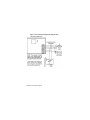
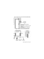
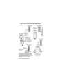
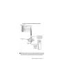
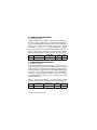
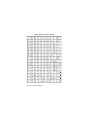
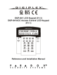
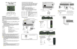
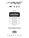
LCD & Access Control LCD Keypad (V1.0)
DGP2-641 / DGP2-641AC
Reference and Installation Manual
DGP-641
© 2002 Paradox Security Systems Ltd.
Digiplex and DigiplexNE are trademarks of Paradox
Security Systems
PosiPIN is a trademark of Position Technology
TABLE OF CONTENTS
1.0 INTRODUCTION ........................................................... 4
1.1 Specifications .................................................................... 5
2.0 INSTALLATION ............................................................. 6
2.1 Connecting Keypad Zones ................................................ 6
2.2 Programmable Output ....................................................... 7
3.0 PROGRAMMING ....................................................... 12
3.1 Entering Module Programming Mode ............................. 12
3.2 Programming Methods .................................................... 13
3.2.1 Feature Select Programming .............................................. 13
3.2.2 Decimal Programming ......................................................... 13
3.3 Module Broadcast ........................................................... 13
4.0 SYSTEM OPTIONS .................................................... 14
4.1 Partition Assignment ....................................................... 14
4.2 Display Access Code Entry ............................................. 14
4.3 Display Exit Delay Timer ................................................. 14
4.4 Display Entry Delay Timer ............................................... 15
4.5 Confidential Mode ........................................................... 15
4.6 Confidential Mode Timer ................................................. 16
4.7 Time Display Option ........................................................ 16
4.8 Muting ............................................................................. 17
4.9 Beep on Exit Delay .......................................................... 17
4.10 Chime on Zone Closure ................................................ 17
4.11 Beep on Trouble ............................................................ 18
4.12 Keypad Tamper Enable ................................................ 18
4.13 Network Voltmeter ......................................................... 19
5.0 FEATURES FOR DGP2-641 ONLY ............................20
5.1 PGM State ....................................................................... 20
5.2 PGM Deactivation Mode ................................................. 20
5.3 PGM Base Time .............................................................. 21
5.4 PGM Override ................................................................. 21
5.5 PGM Timer ...................................................................... 21
5.6 PGM Activation Event ..................................................... 22
5.7 PGM Deactivation Event ................................................. 22
6.0 FEATURES FOR DGP2-641AC ONLY .......................23
6.1 Assigning Doors To Partitions ......................................... 23
6.2 Reader’s Options ............................................................ 23
6.2.1 Reader’s LED To Follow Partition’s Status ..........................24
6.2.2 Reader’s Beep To Follow Partition's Status .........................24
6.2.3 Reader Feedback ................................................................24
6.2.4 Reader's LED Options Upon Access Granted .....................25
6.3 Door Lock Options .......................................................... 25
6.3.1 Unlock on REX (Request For Exit) ......................................25
6.3.2 Door Unlocked Period ..........................................................25
6.3.3 Door Unlocked Period Extension .........................................26
6.3.4 Relock Door .........................................................................26
6.3.5 Door Unlocked Schedule .....................................................26
6.3.6 Card Activates Door Unlocked Schedule .............................27
6.4 Door Left Open Options .................................................. 28
6.4.1 Door Left Open Access Alarm .............................................28
6.4.2 Door Left Open Interval Before Access Alarm .....................29
6.4.3 Door Left Open Pre-Alarm ...................................................29
6.4.4 Door Left Open Pre-Alarm Timer .........................................29
6.4.5 Door Left Open Alarm Feedback .........................................30
6.4.6 Beep Timer For Door Left Open Alarm ............................... 31
6.5 Door Forced Open Options ............................................. 31
6.5.1 Door Forced Open Access Alarm ........................................ 31
6.5.2 Door Forced Open Feedback .............................................. 32
6.5.3 Beep Timer For Door Forced Open Alarm .......................... 32
6.6 Access Control PIN Entry Option .................................... 32
6.6.1 Configuring The PosiPIN’s Keypad ..................................... 33
7.0 MESSAGE PROGRAMMING ..................................... 34
7.1 Special Function Keys ..................................................... 35
8.0 GLOSSARY ................................................................ 37
1.0 INTRODUCTION
Thank you for choosing Paradox® Security Systems. The Digiplex™/
DigiplexNE Security Systems are advanced technology security
systems that will provide reliable security protection and powerful
features that are easy to use. The elegant and user-friendly
Digiplex™/DigiplexNE LCD Keypad will allow easy access to the
security system's functions and information at the touch of a button.
Since all programming is accomplished through the keypad, please
read this manual carefully.
As well as normal security system functions, the Digiplex/DigiplexNE
Access Control LCD Keypad (DGP2-641AC) can also be used for
access control. Access Control is designed to monitor and control the
access for up to 32 designated doors without the need of an
additional control panel. The events that occur on an Access Control
door can be logged in the control panel’s Event Buffer and can be
viewed through the keypad.
Each door to become an Access Control door requires an Access
Control LCD Keypad (DGP2-641AC), a reader (suggestion: PosiProx
CR-R880-A or PosiPIN CR-R885-BL), a REX device (suggestion:
Paradoor 460), a door contact, and a locking device.
If desired, door contacts can also be assigned to zones in the control
panel to link the doors to the Digiplex/DigiplexNE Alarm system. This
will allow you to use the same door for the Access Control system
and the alarm system. Only two of the Access Control features
require that the Access Control door's door contact be assigned to a
zone: Burglar Alarm on Forced Door and Access to Armed Access
Control Doors (refer to the Digiplex or DigiplexNE Reference &
Installation Manual).
4 Reference & Installation Manual
1.1 SPECIFICATIONS
Power input:
PGM current limit:
Number of inputs:
Power indication:
Locate indication:
Network fault
indication:
Tamper Switch:
LCD:
Compatibility:
12 to 16 Vdc, 80mA maximum
50 mA
1 (DGP2-641)
2 (DGP2-641AC)
Yellow LED on
Green and yellow LEDs flash simultaneously
Red and yellow LEDs flash alternately
Yes (also used to deactivate locate)
Super Twisted Nematic display (STN), wide
viewing angle, 2 lines of 16 characters, backlight
and contrast adjustable
DGP2-641: Any Digiplex/DigiplexNE Control
Panel
DGP2-641AC: Any DigiplexNE control panel or
Digiplex control panel V2.20ACC and higher
Digiplex/DigiplexNE LCD Keypad 5n
2.0 INSTALLATION
The LCD keypads (DG2P-641 and DGP2-641AC) are connected to
the control panel's network in a star and/or daisy chain configuration.
This 4-wire communication network provides power and two-way
communication between the control panel and all modules connected
to it. Connect the four terminals labeled red, black, green and yellow
of each keypad to the corresponding terminals on the control panel
(refer to Figure 1 on page 8). Refer to the Digiplex or DigiplexNE
Reference & Installation Manual for the maximum allowable
installation distance from the control panel.
See Figure 4 on page 10 for connection drawings for the REX
device, reader, locking device and door contact to the desired DGP2641AC keypad. A typical installation is shown in Figure 2 on page 9.
The door contact follows the control panel’s EOL
definition. When EOL is enabled and the door contact is
not used, place a 1kΩ resistor across the keypad’s Z1
and BLK input terminals. If EOL is not enabled, use a
jumper. If the REX device is not used, place a jumper
across the keypad’s Z2 and BLK input terminals.
2.1 CONNECTING KEYPAD ZONES
Each keypad has one traditional hardwired input terminal, allowing
you to connect one detector or door contact directly to the keypad.
For example, a door contact located at the entry point of an
establishment can be wired directly to the input terminal of the entry
point keypad instead of wiring the door contact all the way to the
control panel.
Connect the device to the keypad's input terminal as shown in Figure
1 on page 8. In order to communicate its status to the control panel,
devices connected to the keypad's input terminal must be assigned
6 Reference & Installation Manual
to a zone in the control panel and the zone's parameters must be
defined. For more information on zone assignment, please refer to
the Digiplex or DigiplexNE Reference & Installation Manual. Please
note that even with the ATZ (zone doubling) feature enabled, the
keypad supports only one detection device.
2.2 PROGRAMMABLE OUTPUT
Each keypad has one on-board PGM. A PGM is a programmable
output that toggles to its opposite state (i.e. a normally open PGM will
close) when a specific event has occurred in the system (see section
5.0 on page 20). Upon activation, the PGM can provide 50mA to any
device connected to it. If the current drawn is to exceed the current
limit, a relay should be connected to the PGM as shown in Figure 1.
With the DGP2-641AC keypad, the PGM is reserved for the door lock
(refer to Figure 4 on page 10).
Digiplex/DigiplexNE LCD Keypad 7n
Figure 1: Connecting the Keypad and Keypad Zone
8 Reference & Installation Manual
Figure 2: Typical Access Control Installation (DGP2-641AC)
Figure 3: Access Control Overview (DGP2-641AC)
Digiplex/DigiplexNE LCD Keypad 9n
Figure 4: Access Control Connections (DGP2-641AC)
10 Reference & Installation Manual
Figure 5: Connecting a Shielded Routing Cable
Digiplex/DigiplexNE LCD Keypad 11n
3.0 PROGRAMMING
Programming the DGP2-641 or DGP2-641AC LCD keypads is
simple. Enter the Module Programming Mode, enter the desired
section followed by the required data. When programming the
keypad, use the keypad’s programming sheets (found in the Digiplex/
DigiplexNE Modules’ Programming Guide) to keep track of which
sections were programmed and how. We strongly recommend you
read this entire manual before you begin programming.
The LCD keypad can also be programmed using the WinLoad
Security System Management Software. For more information, refer
to the WinLoad instructions or visit our web site at www.paradox.ca.
3.1 ENTERING MODULE PROGRAMMING MODE
The keypad, like all other modules in the system, is programmed
through the control panel. To do so, you must first enter the Module
Programming Mode:
Step 1:
Step 2:
Step 3:
Step 4:
Step 5:
Step 6:
From Normal Mode press and hold the [0] key.
Enter the [INSTALLER CODE] (by default 000000).
Enter section [953] (DGP-48) / [4003] (DGP-NE96).
Enter the keypad’s 8-digit [SERIAL NUMBER].
Enter the 3-digit [SECTION] you want to program.
Enter the required [DATA].
The control panel will then redirect all programming to the selected
keypad. Every time the [CLEAR] key is pressed it will revert to the
preceding step, unless entering in data in which case it will erase the
current data entry. Please note that the serial number is located on
the keypad's PC board or enter section [000] in Step 3 to view the
keypad’s serial number.
12 Reference & Installation Manual
3.2 PROGRAMMING METHODS
The following methods can be used when programming the keypad:
3.2.1 FEATURE SELECT PROGRAMMING
Some sections are programmed by enabling or disabling
options. Within the sections, numbers from [1] to [8] represent
a specific keypad option. Press the key corresponding to the
desired option and the digit will appear in the display. This
means the option is enabled. Press the key again to remove
the digit from the display thereby disabling the option. Press
[ENTER] when options are set.
3.2.2 DECIMAL PROGRAMMING
Some sections require that a decimal value be entered. In this
method, any digit from 000 to 255 can be entered.
3.3 MODULE BROADCAST
The control panel’s Module Broadcast feature can be used to copy
the contents of one keypad to one or many other keypads.
Step 1:
Step 2:
Step 3:
Step 4:
From Normal Mode press and hold the [0] key.
Enter [INSTALLER CODE] (default: 000000).
Enter section [954] (DGP-48) / [4004] (DGP-NE96).
Enter the [SERIAL #] of the source keypad. The source is the
programmed keypad whose data you want to copy to other
keypads.
Step 5: Enter the [SERIAL #] of the destination keypads. The
destination is the keypad(s) you want to program with the
source’s data. If you want to program more than one keypad
with the source’s data, enter the serial numbers of the
keypads one at a time.
Step 6: Once you have entered the serial numbers of the keypads
you want to program, press the [ACC] key.
Digiplex/DigiplexNE LCD Keypad 13n
4.0 SYSTEM OPTIONS
The following sections pertain to the programming of options
belonging to both the DGP2-641 and DGP2-641AC Access Control
LCD keypads.
4.1 PARTITION ASSIGNMENT
SECTION [001]: OPTIONS [1] TO [8]
Each keypad in the system can be assigned to one or more
partitions. In section [001], options [1] to [8] represent partitions 1
through 8 respectively. To assign the keypad to a partition, simply
enable the option that corresponds to the desired partition. By
default, partitions 1 to 8 are enabled.
Section [001] options [5] to [8] can only be used if the
keypad is connected to a DigiplexNE (DGP-NE96) control
panel.
4.2 DISPLAY ACCESS CODE ENTRY
SECTION [003]: OPTION [1]
The digits of the User Access Codes can be displayed on the LCD
screen when they are entered.
Option [1] OFF= Digits are replaced by a * (default).
Option [1] ON = Access Code digits will be displayed.
4.3 DISPLAY EXIT DELAY TIMER
SECTION [003]: OPTION [2]
Based on the user's needs, an Exit Delay Timer will be programmed
to provide the user time to exit the partition before the system is
armed. The Exit Delay Timer's countdown can be displayed on the
LCD screen.
14 Reference & Installation Manual
Option [2] OFF= Will not display Exit Delay timer (default).
Option [2] ON = LCD screen will display Exit Delay timer.
4.4 DISPLAY ENTRY DELAY TIMER
SECTION [003]: OPTION [3]
Based on the user's needs, an Entry Delay Timer will be
programmed to provide the user time to enter their User Access
Code before the alarm is triggered. The Entry Delay Timer's
countdown can be displayed on the LCD screen.
Option [3] OFF= Will not display the Entry Delay Timer (default).
Option [3] ON = LCD screen will display Entry Delay Timer.
4.5 CONFIDENTIAL MODE
SECTION [003]: OPTIONS [4] AND [5]
If the Confidential Mode is enabled and no actions are performed on
the keypad for a period of time, the LCD screen will appear as shown
in Figure 6 (page 16) and the “AC” and “STATUS” LED will be off until
either a button is pressed or an access code is entered. The period of
time in which no action is performed is defined by the Confidential
Mode Timer (005-255 seconds; refer to section 4.6 on page 16).
Confidential Mode is activated by enabling option [4]. Option [5]
regulates whether the LCD screen will be activated at the touch of a
button or only when an access code is entered.
Once the LCD screen is activated (by code or button), Normal Mode
will appear and display the date and time as shown in Figure 6 on
page 16. The status of the areas, the open zones for every area the
keypad is assigned, the Alarm Memory Display (if necessary) and the
Trouble Display (if necessary. See Digiplex or DigiplexNE User
Manual) will also scroll on the LCD screen. By default, options [4]
and [5] are OFF.
Digiplex/DigiplexNE LCD Keypad 15n
Section [003]:
Option [4] OFF= Normal Mode
Option [4] ON = Confidential Mode
Option [5] OFF= LCD screen activated by entering an access code
Option [5] ON = LCD screen activated by pressing a button
Figure 6: LCD Screen
4.6 CONFIDENTIAL MODE TIMER
SECTION [007]
Section [007] determines the amount of time without action before
the keypad enters Confidential Mode. For more information on
Confidential Mode, refer to “Confidential Mode” on page 15. The
Confidential Mode Timer can be set from 005 seconds to 255
seconds. Default: 120 seconds.
4.7 TIME DISPLAY OPTION
SECTION [003]: OPTION [8]
The LCD keypad comes with a time display option that can display
the date as year/month/day or as day/month/year.
Option [8] OFF= Date displayed as yy/mm/dd (default).
Option [8] ON = Date displayed as dd/mm/yy.
16 Reference & Installation Manual
4.8 MUTING
SECTION [004]: OPTION [1]
The keypad can be programmed not to emit audible sounds,
including Chimed zones. During Muting, the keypad will only emit the
Confirmation Beep, Rejection Beep, and beep when a button is
pressed.
Option [1] OFF= Audible sounds (default).
Option [1] ON = Mute.
4.9 BEEP ON EXIT DELAY
SECTION [004]: OPTION [2]
The keypad can beep once every second during the Exit Delay
Timer. During the final 10 seconds, it will beep more rapidly to
provide a final warning before the area is armed.
Option [2] OFF= Exit Delay beep disabled.
Option [2] ON = Exit Delay beep enabled (default).
4.10 CHIME ON ZONE CLOSURE
SECTION [004]: OPTION [4]
During the Chime Zone Time Period that the user sets, the keypad
can emit an intermittent beep whenever a zone with the Chime
feature enabled closes (see Digiplex or DigiplexNE User Manual for
details on Chime Zones). If the user does not set the Chime Zone
Time Period and this option is enabled, the Chime Zones will always
beep upon closure.
Option [4] OFF= Chime on Zone Closure disabled (default).
Option [4] ON = Chime on Zone Closure enabled.
Digiplex/DigiplexNE LCD Keypad 17n
4.11 BEEP ON TROUBLE
SECTION [005]: OPTIONS [1] TO [4]
Potential troubles have been sorted into groups. With these options
enabled, the keypad will emit an intermittent beep tone whenever a
trouble condition from the Trouble Groups occurs in the system. The
intermittent beep will remain activated until the user enters the
Trouble Display or if the trouble is resolved. For a list of the troubles,
see the Digiplex or DigiplexNE Reference and Installation Manual.
The intermittent beep will be re-initialized whenever the trouble
condition re-occurs. By default, options [1] to [4] are OFF.
Option [1] OFF= Beep disabled: System Troubles and Clock Loss.
Option [1] ON = Beep enabled: System Troubles and Clock Loss.
Option [2] OFF= Beep disabled: Communicator Troubles.
Option [2] ON = Beep enabled: Communicator Troubles.
Option [3] OFF= Beep disabled: Module and Network Troubles.
Option [3] ON = Beep enabled: Module and Network Troubles.
Option [4] OFF= Beep disabled: all Zone Troubles.
Option [4] ON = Beep enabled: all Zone Troubles.
4.12 KEYPAD TAMPER ENABLE
SECTION [006]: OPTION [5]
When tamper is enabled and the keypad's on-board tamper switch is
triggered, the keypad will send a Tamper report to the control panel
via the communication network.
Option [5] OFF= Keypad's tamper is disabled (default).
Option [5] ON = Keypad's tamper is enabled.
18 Reference & Installation Manual
4.13 NETWORK VOLTMETER
The Network Voltmeter provides a real-time display of the voltage so
you can verify if the network is supplying sufficient power at the
keypad’s location. The readings will appear on the LCD screen. A
reading of 10.5V indicates that the voltage is too low. This may occur
when too many modules are connected to the network, a module is
installed too far from the panel or if the system is running on the
battery. In some cases adding an external power supply may correct
the situation.
Step 1: From Normal Mode press and hold the [0] key.
Step 2: Enter the [INSTALLER CODE] (by default 000000).
Step 3: Press [ACC].
The voltage may drop during the control panel battery test.
Digiplex/DigiplexNE LCD Keypad 19n
5.0 FEATURES FOR DGP2-641 ONLY
The following sections pertain to the programming of options
belonging to the DGP2-641 LCD keypad only.
5.1 PGM STATE
SECTION [006]: OPTION [1]
The keypad's on-board PGM can be set as normally open or
normally closed. When an open PGM is activated, it will close the
circuit from ground and enable any devices connected to it. When a
closed PGM is activated, it will open the circuit and disable any
devices connected to it. When the PGM Activation Event occurs (see
section 5.6), the PGM will switch to its opposite state (i.e. open to
closed or closed to open).
Option [1] OFF= PGM is Normally Open (default).
Option [1] ON = PGM is Normally Closed.
The PGM can provide 50mA to any device connected to it.
5.2 PGM DEACTIVATION MODE
SECTION [006]: OPTION [2]
If the keypad is in PGM Timed Mode, the keypad's on-board PGM
will be deactivated according to the PGM Timer (see section 5.5
below) instead of the PGM Deactivation Event.
Option [2] OFF= Deactivates on PGM Deactivation Event (default).
Option [2] ON = PGM will deactivate according to the PGM Timer.
20 Reference & Installation Manual
5.3 PGM BASE TIME
SECTION [006]: OPTION [3]
If the keypad's on-board PGM is set in PGM Timed Mode (see
section 5.2 on page 20) you must define whether the value
programmed in section [008] is in minutes or seconds.
Option [3] OFF= PGM Base Time is 1 second (default).
Option [3] ON = PGM Base Time is 1 minute.
5.4 PGM OVERRIDE
SECTION [006]: OPTION [4]
When the PGM override is enabled, the keypad's on-board PGM will
ignore PGM Activation Events (section 5.6, page 22), PGM
Deactivation Events (section 5.7, page 22), and PGM Timers (section
5.5, page 21). It will remain in its normal state until the PGM Override
is disabled. This option may be used to test the PGM connections.
Option [4] OFF= PGM Override disabled (default).
Option [4] ON = PGM Override enabled.
5.5 PGM TIMER
SECTION [008]
If the keypad's on-board PGM is in PGM Timed Mode, the value
programmed in section [008] represents how long the PGM will
remain in its opposite state (see section 5.1 on page 20) after being
activated. To program the timer, enter a 3-digit decimal value (000 to
255) in section [008]. The 3-digit value will be multiplied by the PGM
Base Time of 1 second or 1 minute (see section 5.3 above). Default:
5 seconds.
Digiplex/DigiplexNE LCD Keypad 21n
5.6 PGM ACTIVATION EVENT
SECTIONS [009] TO [012]
The PGM Activation Event determines which event will activate the
keypad's on-board PGM output. The EVENT GROUP specifies the
event, the FEATURE GROUP identifies the source, and the START # and
END # sets the range within the Feature Group. Use the PGM
Programming Table in the Digiplex/DigiplexNE Modules’
Programming Guide to program the keypad’s PGM Activation Event.
Enter the sections that correspond to the EVENT GROUP, FEATURE
# and END # of the PGM and enter the required data.
GROUP, START
PGM
EVENT GROUP
FEATURE GROUP
[009]
[010]
START
#
[011]
END
#
[012]
5.7 PGM DEACTIVATION EVENT
SECTIONS [013] TO [016]
If the PGM Deactivation Option (section 5.2 on page 20) is set to
follow the PGM Deactivation event, the PGM will return to its normal
state when the event programmed in sections [013] to [016] occurs.
The EVENT GROUP specifies the event, the FEATURE GROUP identifies
the source, and the START # and END # sets the range within the
Feature Group. Use the PGM Programming Table in the Digiplex/
DigiplexNE Modules’ Programming Guide to program the keypad’s
PGM Activation Event.
Enter the sections that correspond to the EVENT GROUP, FEATURE
GROUP, START # and END # of the PGM and enter the required data.
PGM
EVENT GROUP
FEATURE GROUP
[013]
[014]
22 Reference & Installation Manual
START
#
[015]
END
#
[016]
6.0 FEATURES FOR DGP2-641AC ONLY
The following sections pertain to the programming of options
belonging to the DGP2-641AC Access Control LCD keypad only.
6.1 ASSIGNING DOORS TO PARTITIONS
SECTION [002]: OPTIONS [1] TO [8]
Although the keypad can be programmed to display the status of
various partitions, the Access Control door can be assigned to one or
more partition(s) in the alarm system. This means that the actions
performed with the Access Control Card will be directly linked to the
partition(s) assigned to that door. For example, the keypad is
assigned to all eight partitions (see section 4.1 on page 14), but the
door is assigned to Partition 2. When the user presents the Access
Control Card to the door's reader to arm the partition, only Partition 2
will arm.
Option [1] ON
Option [2] ON
Option [3] ON
Option [4] ON
Option [5] ON
Option [6] ON
Option [7] ON
Option [8] ON
OFF
= door assigned to Partition 1(default).
= door assigned to Partition 2.
= door assigned to Partition 3.
= door assigned to Partition 4.
= door assigned to Partition 5 (DigiplexNE only).
= door assigned to Partition 6 (DigiplexNE only).
= door assigned to Partition 7 (DigiplexNE only).
= door assigned to Partition 8 (DigiplexNE only).
= Access Control Cards will not be able to arm and/or
disarm partitions from the door's reader.
6.2 READER’S OPTIONS
The reader’s LED and beep features can be programmed to react in
certain ways when a specific function is performed.
Digiplex/DigiplexNE LCD Keypad 23n
6.2.1 READER ’S LED TO FOLLOW PARTITION’S STATUS
SECTION [003]: OPTION [6]
The reader's LED can be programmed to flash according to
the partition's status. When this feature is enabled, the
reader’s red LED will flash when the partition is arming, in Exit
Delay, in Entry Delay, in Burglar Alarm or in Fire Alarm.
Option [6] OFF= The reader's LED will not flash.
Option [6] ON = LED follows the door’s partition status
(default).
6.2.2 READER ’S BEEP TO FOLLOW PARTITION'S STATUS
SECTION [003]: OPTION [7]
This feature will only function when section [003] option [6] is
enabled. The reader can be programmed to beep according to
its keypad's beep when the partition assigned to the door is
arming, in Exit Delay, in Entry Delay, in Burglar Alarm, or in
Fire Alarm.
Option [7] OFF= The beep will not follow the partition's status.
Option [7] ON = Beep follows the partition's status (default).
6.2.3 READER FEEDBACK
SECTION [005]: OPTION [8]
The reader can be programmed to give visual feedback only
(the reader’s LED flashing) or both visual and audible
feedback (the reader will flash and beep).
Option [8] OFF= The reader’s feedback is visual only (default).
Option [8] ON = The reader’s feedback is both visual &
audible.
24 Reference & Installation Manual
6.2.4 READER'S LED OPTIONS UPON ACCESS GRANTED
SECTION [006]: OPTION [7]
When the Access Control card is presented to the reader, the
reader's LED can be programmed to turn green during the
door’s unlocked period (or until the door closes) or extinguish
briefly to indicate that the door is unlocked.
Option [7] OFF= The reader's red LED will extinguish briefly.
Option [7] ON = The reader's red LED will turn green (default).
6.3 DOOR LOCK OPTIONS
The Door Lock Options allow you to program the door lock to suit its
environment or security requirements.
6.3.1 UNLOCK ON REX (REQUEST FOR EXIT)
SECTION [006]: OPTION [8]
When the REX device detects movement, it can permit
passage with or without turning the door handle. If this option
is on, the door is unlocked when the REX device detects
movement and users on either side of the door will be able to
open the door. If this option is off, the door will unlock once the
handle is turned only on the REX device’s side.
Option [8] OFF= Unlock on REX disabled (default).
Option [8] ON = Unlock on REX enabled.
6.3.2 DOOR UNLOCKED PERIOD
SECTION [008]
The Door Unlocked Period is the time the door can remain
unlatched after access is granted or after a Request for Exit is
received. Enter any value between 001 and 255 to determine
the seconds the door can remain unlatched. Default = 5
seconds.
Digiplex/DigiplexNE LCD Keypad 25n
6.3.3 DOOR UNLOCKED PERIOD EXTENSION
SECTION [009]
The Door Unlocked Period Extension is the amount of time
added to the Door Unlocked Period in section [008], which
leaves the door unlatched longer. This will allow those with this
feature enabled on their User Access Codes extra time to
enter, which may be useful for the physically challenged or for
seniors. Enter any value between 001 and 255 to determine
the number of seconds to be added to the time programmed in
section [008]. Default = 15 seconds.
6.3.4 RELOCK DOOR
SECTION [006]: OPTION [6]
The locking device will remain unlatched during the Door
Unlocked Period (see section 6.3.2 on page 25), but once the
door is opened it can be programmed to latch as soon as the
door closes or latch immediately even if the door has not
closed.
Option [6] OFF= Locking device latches immediately (default).
Option [6] ON = Locking device latches when door closes.
6.3.5 DOOR UNLOCKED SCHEDULE
SECTION [017]
The Door Unlocked Schedule determines the hours, days, and
holidays that the door will remain unlocked. Therefore, users
will not have to present their Access Control Cards to the
reader in order to gain access to an Access Control Door
during the Door Unlocked Schedule. The schedule consists of
two programmable time periods called “Intervals” that
determine the time of day and which days the users will be
granted access. When a schedule is programmed with “H”,
26 Reference & Installation Manual
users will have access during the days programmed in the
control panel (refer to the Digiplex or DigiplexNE Reference &
Installation Manual).
Program the Start Time and End Time according to the 24hour clock within the same day. Use Feature Select
Programming to set the options representing the Days.
Option
[1]
[2]
[3]
[4]
Day
SUNDAY (S)
MONDAY (M)
TUESDAY (T)
WEDNESDAY (W)
Option
[5]
[6]
[7]
[8]
Day
THURSDAY (T)
FRIDAY (F)
SATURDAY (S)
HOLIDAYS (H)
For example, program:
•
•
Interval A: Start time 07:00, End time 16:00, Days M, T,
W, T, & F
Interval B: Start time 10:00, End time 17:00, Days S, S,
&H
Then, the door will stay unlocked on Monday, Tuesday,
Wednesday, Thursday, and Friday between 7AM and 4PM and
on Saturday, Sunday, and Holidays between 10AM and 5PM.
Therefore, users will not have to present their Access Control
Cards during the Door Unlocked Schedule.
6.3.6 CARD ACTIVATES DOOR UNLOCKED SCHEDULE
SECTION [006]: OPTION [1]
When the Door Unlocked Schedule is programmed and this
option is enabled, the door is locked until the first valid Access
Control Card is presented. Once the door is unlocked, it will
remain unlocked until the end of the schedule.
For example: The schedule is 7AM to 5PM Monday to Friday,
option [1] is enabled, and a valid Access Control Card is
presented to the reader at 8AM on Monday. Although the
Digiplex/DigiplexNE LCD Keypad 27n
schedule started at 7AM, the door remained locked from 7AM
to 8AM. Once access was granted at 8AM, the door remained
unlocked until 5PM.
Option [1] OFF= The Schedule activates without Card (default).
Option [1] ON = Card activates Door Unlocked Schedule.
6.4 DOOR LEFT OPEN OPTIONS
The Door Left Open Options allow you to program how the system
will react to an Access Control door left open.
6.4.1 DOOR LEFT OPEN ACCESS ALARM
SECTION [006]: OPTION [2]
When an Access Control door is opened after an Access
Granted or a Request for Exit, an Access Alarm can be
generated if it not closed within a certain period of time (see
section 6.4.2 on page 29).
Option [2] OFF= Door Left Open Alarm will not be generated
(default).
Option [2] ON = Door Left Open Alarm is enabled.
When the Door Left Open Alarm is disabled, the following
sections are also disabled:
Section
[004] Option [3] Door Left Open Pre-alarm
Option [5] Door Left Open Alarm
Option [6] Door Left Open Alarm follows
[010] Door Left Open Interval
[011] Door Left Open Pre-alarm Timer
[012] Beep Timer for Door Left Open Alarm
28 Reference & Installation Manual
6.4.2 DOOR LEFT OPEN INTERVAL BEFORE ACCESS ALARM
SECTION [010]
The Door Left Open Interval is the time that a door can remain
open after an Access Granted or a Request for Exit without
generating an Access Alarm. Enter any value between 001
and 255 to determine the number of seconds the door may
remain open before the Access Alarm is triggered. Default =
60 seconds.
6.4.3 DOOR LEFT OPEN PRE-ALARM
SECTION [004]: OPTION [3]
If an Access Control door is programmed with a Door Left
Open Interval (see section 6.4.2 above), the Pre-Alarm will
cause the reader to beep a certain time before the end of the
Door Left Open Interval to alert users that the Access Control
door was left open and will generate an Access Alarm if it is
not closed. The Pre-Alarm beeps slower than the Door Left
Open Alarm (about twice every second). Program the PreAlarm timer in section [011].
Option [3] OFF= The Pre-Alarm will not be generated.
Option [3] ON = Pre-Alarm is enabled (default).
6.4.4 DOOR LEFT OPEN PRE-ALARM TIMER
SECTION [011]
This timer will trigger the Door Left Open Pre-Alarm before the
end of the Door Left Open Interval (see section 6.4.3 above).
For example, if 60 seconds is programmed in section [010] and
15 seconds is programmed in section [011], then 60 minus 15 is
45. Therefore, the reader will start beeping after the door has
been open for 45 seconds. Enter any value between 001 and
255 to determine the seconds before the expiry of the Door Left
Open Interval that the reader will beep. Default = 15 seconds.
Digiplex/DigiplexNE LCD Keypad 29n
Figure 7: Pre-Alarm example
6.4.5 DOOR LEFT OPEN ALARM FEEDBACK
SECTION [004]: OPTIONS [5] AND [6]
An Access Control door is programmed with a Door Left Open
Interval (see section 6.4.2 on page 29). Once this interval has
expired, the Door Left Open Alarm can be either audible or
silent and will either beep as long as the Access Alarm is
occurring or follow the Beep Timer in section [012]. The sound
of the Door Left Open Alarm resembles the rapid beep
generated during the last ten seconds of the Exit Delay. When
the door is closed during an Access Alarm, the Door Left Open
Restore event can be logged in the Event Buffer.
Option [5] OFF= The Door Left Open Alarm is silent.
Option [5] ON = The Door Left Open Alarm is audible
(default).
If option [5] is enabled:
Option [6] OFF= beep as long as the Door Left Open Alarm is
occurring (default).
Option [6] ON = Door Left Open Alarm follows Beep Timer
(section [012]).
30 Reference & Installation Manual
6.4.6 BEEP TIMER FOR DOOR LEFT OPEN ALARM
SECTION [012]
This beep timer determines the amount of time the Door Left
Open Alarm will beep. Once the Door Left Open Interval (see
section 6.4.2 on page 29) has expired, the Door Left Open
Alarm (see section 6.4.5 on page 30) will be triggered. Enter
any value between 001 and 255 to determine the number of
seconds the Access Alarm will beep. Default = 5 seconds.
6.5 DOOR FORCED OPEN OPTIONS
The Door Forced Open Options allow you to program how the
system will react when an Access Control door is opened without a
“Request for Exit” or “Access Granted” signal.
6.5.1 DOOR FORCED OPEN ACCESS ALARM
SECTION [006]: OPTION [3]
If an Access Control door is opened without an Access Control
Card, a User Access Code or receiving a Request for Exit, an
Access Alarm can be generated. A Burglar Alarm can also be
generated. When the door is closed during an Access Alarm,
the Door Forced Open Restore event can be logged in the
Event Buffer.
Option [3] OFF= Door Forced Open Alarm is disabled (default).
Option [3] ON = Door Forced Open Alarm is enabled.
When the Door Forced Open Alarm is disabled, the following
sections are also disabled:
Section
[004]
[013]
OPTION [7] DOOR FORCED OPEN ALARM
OPTION [8] DOOR FORCED OPEN ALARM FOLLOWS
BEEP TIMER FOR DOOR FORCED OPEN ALARM
Digiplex/DigiplexNE LCD Keypad 31n
6.5.2 DOOR FORCED OPEN FEEDBACK
SECTION [004]: OPTIONS [7] AND [8]
The Access Alarm can be either audible or silent and will either
beep as long as the Access Alarm is occurring or follow the
Beep Timer in section [013]. The sound of the Door Forced
Open Alarm resembles the rapid beep generated during the
last ten seconds of the Exit Delay.
Option [7] OFF= Door Forced Open Alarm is silent.
Option [7] ON = Door Forced Open Alarm is audible (default).
If option [7] is enabled:
Option [8] OFF= will beep as long as Door Forced Open Alarm
is occurring (default).
Option [8] ON = Door Forced Open Alarm follows Beep Timer.
(section [013]).
6.5.3 BEEP TIMER FOR DOOR FORCED OPEN ALARM
SECTION [013]
This Beep Timer determines the amount of time the Door Forced
Open Alarm (see section 6.5.2 above) will beep. Enter any value
between 001 and 255 to determine the number of seconds the
Door Forced Open Alarm will beep. Default = 5 seconds.
6.6 ACCESS CONTROL PIN ENTRY OPTION
SECTION [006]: OPTION [4]
If the Card and Code Access option is enabled in the DigiplexNE
control panel (refer to the Access Control section in the DigiplexNE
Reference & Installation Manual), the Access Control PIN Entry
option determines whether the PIN is entered on the Access Control
LCD keypad or on a PosiPIN Proximity Reader (CR-R885-BL). If the
reader being used is a PosiPIN and section [006] option [4] is ON,
the user must present their access control card to the reader and
32 Reference & Installation Manual
enter their PIN on the PosiPIN reader. If section [006] option [4] is
OFF, the user must present their access control card to the reader
and enter their PIN on the keypad.
Option [4] OFF= User enters their PIN on the keypad (default).
Option [4] ON = User enters their PIN on the PosiPIN.
Section [006] option [4] can only be used if connected to a
DigiplexNE (DGP-NE96) control panel. Do not enable
section [006] option [4] if using a normal proximity reader.
6.6.1 CONFIGURING THE POSIPIN’S KEYPAD
In order for the Access Control PIN Entry option (section 6.6
on page 32) to work with the DigiplexNE, the PosiPIN’s keypad
communication format must be set to 8-bit Wiegand. To do so,
from the PosiPIN, perform the following:
Step 1: Press and hold the [CLEAR] key for 4 seconds (the
reader emits a confirmation beep and the green LED
illuminates).
Step 2: Enter the PosiPIN’s [INSTALLER CODE] (default:
000000) and press the [ENTER] key (reader emits a
confirmation beep and the green LED flashes).
Step 3: Enter section [002] and press the [ENTER] key (reader
emits a confirmation beep and the green LED stops
flashing).
Step 4: Press the [0] key (8-bit-Wiegand) and press the
[ENTER] key (reader emits a confirmation beep and
the green LED flashes).
Step 5: Press and hold the [CLEAR] key for 4 seconds to exit
programming mode (the reader emits a rejection
beep and the green LED extinguishes).
For more information, please refer to the PosiPIN Installation
and Operating Instructions.
Digiplex/DigiplexNE LCD Keypad 33n
7.0 MESSAGE PROGRAMMING
SECTIONS [101] TO [148], [200] TO [204], and [301] TO [396]
Each section contains one message with a maximum of 16
characters. For more details and to record any changes, use the
Digiplex/DigiplexNE Modules’ Programming Guide.
Section [101] to [148] = “Zone 01” to “Zone 48” respectively
Section [200] = “Paradox Family”
Section [201] to [204] = “First Area”, “Second Area”, “Third Area”,
and “Fourth Area” respectively
Section [301] to [396] = “Code 01” to “Code 96” respectively
After entering the section corresponding to the desired message, use
the Message Programming Keys (see Table 1) and the Special
Function Keys on page 35 to change the message to suit your
installation needs. For example, section [101] “ZONE 01” can be
changed to “FRONT DOOR”.
Table 1: Message Programming Keys
Key
[1]
[2]
[3]
[4]
[5]
[6]
[7]
[8]
[9]
Press Key Once Press Key Twice
A
D
G
J
M
P
S
V
Y
34 Reference & Installation Manual
B
E
H
K
N
Q
T
W
Z
Press Key Three
Times
C
F
I
L
O
R
U
X
The DigiplexNE control panel has up to 8 partitions, 96 zones
and up to 999 user codes. The LCD keypad only allows you
to program the messages for up to 4 partitions, 48 zones and
96 user codes. The rest of the messages can be
programmed directly into the DigiplexNE control panel. Refer
to the DigiplexNE Reference & Installation Manual and to the
DigiplexNE Programming Guide for more details.
7.1 SPECIAL FUNCTION KEYS
[STAY] - Insert Space
Pressing the [STAY] key inserts a blank space in the current cursor
position.
[FORCE] - Delete
Pressing the [FORCE] key will delete the character or blank space
found at the current cursor position.
[ARM] - Delete Until the End
Pressing the [ARM] key will delete all characters and spaces to the
right of the cursor and at the cursor's position.
[DISARM] - Numeric Keys / Alphanumeric Keys
Every time the [DISARM] key is pressed it will toggle numeric keys to
alphanumeric keys and vice versa. Numeric: Keys [0] to [9]
represent numbers 0 to 9
[BYP] - Lower Case / Upper Case
Every time the [BYP] key is pressed it will toggle the case setting from
lower to upper case and vice versa.
[MEM] - Special Characters
After pressing the [MEM] key, the cursor will turn into a flashing black
square. Using Table 2 on the following page, enter the 3-digit number
that represents the desired symbol.
Digiplex/DigiplexNE LCD Keypad 35n
Table 2: Special Characters Catalog
36 Reference & Installation Manual
8.0 GLOSSARY
Access Alarm:
An audible or silent warning generated by the
reader to indicate that a protected door has not
closed within the programmed time allowed or
that a protected door was opened without an
“Access Granted” or “Request for Exit” signal. If
the Access Alarm is programmed to be audible,
the reader assigned to the door can beep. This
event is logged in the Event Buffer, but can only
be seen through an Access Control keypad
(DGP2-641AC).
Access Control:
A system designed to monitor and control the
admission through specific doors.
Access Control
card:
A tag assigned to a User Access Code used to
identify the user to the Access Control system.
By presenting the tag to a reader, the system
can verify whether the tag is valid (see Valid
Access Control Card).
Access Denied:
An Access Control term for the system’s refusal
to admit access through a protected door.
Access Granted:
An Access Control term for the system
permitting admission through a protected door.
Access Level:
The combination of Access Control doors that
will be assigned to users through their User
Access Codes. Users will only be permitted to
enter through the protected doors that are
programmed in their Access Level.
Burglar Alarm:
An audible or silent warning sent to the control
panel indicating that an armed zone in the
system has been breached. This event is logged
Digiplex/DigiplexNE LCD Keypad 37n
in the Event Buffer and can be reported to a
Monitoring Station.
Door Left Open:
Each Access Control door is programmed with a
period of time it is allowed to remain open. Once
the door has been open past this time limit, an
Access Alarm will be triggered (see Access
Alarm).
Event Buffer:
The user-initiated actions, alarms, and troubles
that occur in the system are saved in the control
panel’s memory: the Event Buffer. To view the
events you must enter the Event Record Display
(see Digiplex or DigiplexNE Reference &
Installation Manual). The Access Control events,
however, can only be viewed through an Access
Control Keypad (DGP2-641AC).
Forced Door:
If a protected door was opened without an
“Access Granted” or “Request for Exit” signal, a
silent or audible Access Alarm can be triggered.
If the Access Alarm is programmed to be
audible, the reader assigned to the door can
beep. This event is logged in the Event Buffer,
but can only be seen through an Access Control
keypad (DGP2-641AC) and cannot be reported
to a Monitoring Station unless the door is also
assigned to a zone. If the door is assigned to a
zone, the Forced Door can also trigger a Burglar
Alarm in the system.
38 Reference & Installation Manual
Holidays:
Days programmed in the control panel that are
not considered normal work days, such as legal,
religious, and feast days.
Pre-Alarm:
A beep tone warning that an Access Alarm will
be generated if a protected door is not closed
within a specified period.
Reader:
An Access Control device (PosiProx CR-R880-A
or PosiPIN CR-R885-BL) normally located near
a protected door that serves to relay the
information from an Access Control card
presented to it to the control panel.
Request for Exit:
When a REX device (Paradoor 460) installed
above an Access Control door within a protected
area detects movement, it sends a signal to the
control panel to permit a user to leave the
protected area. This signal is a “Request for
Exit” event that is logged in the Event Buffer, but
can only be seen through an Access Control
keypad (DGP2-641AC) and cannot be reported
to a Monitoring Station.
Schedule:
Schedules determine the hours, days, and
holidays that users are permitted access.
Valid Card:
An Access Control card presented to a reader
during its assigned Schedule and within its
assigned Access Level.
Digiplex/DigiplexNE LCD Keypad 39n
Warranty
The Seller warrants its products to be free from defects in materials
and workmanship under normal use for a period of one year. Except
as specifically stated herein, all express or implied warranties
whatsoever, statutory or otherwise, including without limitation, any
implied warranty of merchantability and fitness for a particular
purpose, are expressly excluded. Because Seller does not install or
connect the products and because the products may be used in
conjunction with products not manufactured by Seller, Seller cannot
guarantee the performance of the security system. Seller obligation
and liability under this warranty is expressly limited to repairing or
replacing, at Seller's option, any product not meeting the
specifications. In no event shall the Seller be liable to the buyer or
any other person for any loss or damages whether direct or indirect
or consequential or incidental, including without limitation, any
damages for lost profits, stolen goods, or claims by any other party
caused by defective goods or otherwise arising from the improper,
incorrect, or otherwise faulty installation or use of the merchandise
sold.
PRINTED IN CANADA - 04/2002
DGP2641-EI07