1
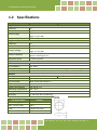
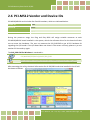
PCI-M512/M512U User Manual 512 KB Memory Board with DI/DO Version 2.8, Sep. 2015 SUPPORT This manual relates to the following boards: PCI-M512 and PCI-M512U WARRANTY All products manufactured by ICP DAS are warranted against defective materials for a period of one year from the date of delivery to the original purchaser. WARNING ICP DAS assumes no liability for damages consequent to the use of this product. ICP DAS reserves the right to change this manual at any time without notice. The information furnished by ICP DAS is believed to be accurate and reliable. However, no responsibility is assumed by ICP DAS for its use, nor for any infringements of patents or other rights of third parties resulting from its use. COPYRIGHT Copyright © 2015 by ICP DAS. All rights are reserved. TRADEMARKS Names are used for identification purposes only and may be registered trademarks of their respective companies. CONTACT US If you have any question, feel to contact us by email at: Email: [email protected] or [email protected] We will respond to you within 2 working days. 512 KB Memory Board with DI/DO TABLE OF CONTENTS PACKING LIST ................................................................................................................................................................ 3 1. INTRODUCTION ................................................................................................................................................. 4 1.1 FEATURES .............................................................................................................................................................. 5 1.2 SPECIFICATIONS ...................................................................................................................................................... 6 2. HARDWARE CONFIGURATION ............................................................................................................................ 7 2.1 BOARD L AYOUT ...................................................................................................................................................... 7 2.2 PIN ASSIGNMENTS .................................................................................................................................................. 8 2.3 DIO BLOCK DIAGRAM ............................................................................................................................................. 9 2.4 BATTERY STATUS INDICATORS .................................................................................................................................. 10 2.5 SRAM STATUS INDICATORS .................................................................................................................................... 12 2.6 PCI-M512 VENDOR AND DEVICE IDS ...................................................................................................................... 13 3. HARDWARE INSTALLATION ...............................................................................................................................14 4. SOFTWARE INSTALLATION ................................................................................................................................18 4.1 OBTAINING/INSTALLING THE DRIVER INSTALLER PACKAGE ............................................................................................. 18 4.2 PNP DRIVER INSTALLATION ..................................................................................................................................... 21 4.3 VERIFYING THE INSTALLATION .................................................................................................................................. 23 4.3.1 Accessing Windows Device Manager ........................................................................................................ 23 4.3.2 Check the Installation ................................................................................................................................ 26 5. 6. TESTING THE PCI-M512 BOARD.........................................................................................................................27 5.1 SELF-TEST WIRING................................................................................................................................................ 27 5.2 EXECUTE THE TEST PROGRAM ................................................................................................................................. 28 DEMO PROGRAM .............................................................................................................................................30 APPENDIX: DAUGHTER BOARD ....................................................................................................................................31 A1. DB-16P ................................................................................................................................................................ 31 A2. DB-16R Relay Board ............................................................................................................................................ 32 A3. DB-24PR, DB-24POR, DB-24C .............................................................................................................................. 33 REPORTING PROBLEMS ...............................................................................................................................................34 User Manual, Ver. 2.8, Sep. 2015, PMH-017-28 Page: 2 512 KB Memory Board with DI/DO Packing List The shipping package includes the following items: One PCI-M512/M512U Series board. One printed Quick Start Guide One software utility CD Note: If any of these items is missing or damaged, contact the dealer from whom you purchased the product. Save the shipping materials and carton in case you need to ship or store the product in the future. User Manual, Ver. 2.8, Sep. 2015, PMH-017-28 Page: 3 512 KB Memory Board with DI/DO 1. Introduction The PCI-M512/PCI-M512U is a 512 KB SRAM memory Board with battery-backup. The PCI-M512U supports both 3.3 V and 5 V Universal PCI bus, while the PCI-M512 only supports the 5 V PCI bus. Both the PCI-M512 and PCI-M512U provide 12 Digital Input channels and 16 Digital Output channels, and the PCI-M512U is designed as a direct replacement for the PCI-M512, without requiring any modification to the software or the driver. A DB-16P daughterboard can be used to connect the input ports (CN2) for isolation purposes, or uses a DB-16R daughterboard as an interface to the output ports (CN1) to provide relay control. The PCI-M512/PCI-M512U is equipped with two Li-ion batteries to ensure that the content of the SRAM is maintained if a power loss occurs. The batteries can continue supplying power to the SRAM for 10 years, ensuring that any important data is retained. The main benefit of the doublet battery design is that either of the batteries can be replaced without losing data, so when one battery is removed, the other continues to provide power to the SRAM. Four LED indicators are included on the board to provide clear visual indication of whether the batteries are operating normally, whether the voltage is low or whether the battery is bad or has encountered a fault. The PCI-M512/PCI-M512U board is an ideal solution for improving system reliability. User Manual, Ver. 2.8, Sep. 2015, PMH-017-28 Page: 4 512 KB Memory Board with DI/DO 1.1 Features PCI-M512 board, supports the 5 V PCI bus. PCI-M512U Universal PCI board, supports both the 3.3 V and the 5 V PCI bus. On-board 512 KB SRAM Two Li-ion batteries, BT1 & BT2, to provide battery backup of SRAM data LED Indicators to monitor the status of the Li-ion batteries normal, low voltage, fault 16-bit general purpose TTL-compatible Digital Output 12-bit general purpose TTL-compatible Digital Input (DI4 to 15) 4-bit battery status read back(DI0 to 3) User Manual, Ver. 2.8, Sep. 2015, PMH-017-28 Page: 5 512 KB Memory Board with DI/DO 1.2 Specifications Model Name Digital Input Channels Compatibility Input Voltage Response Speed Digital Output Channels Compatibility Output Voltage Output Capability Response Speed Special SRAM Size Li-ion Battery Battery Status Bits LED Indicators General Bus Type Data Bus I/O Connector Dimensions (L x W x D) Power Consumption Operating Temperature Storage Temperature Humidity PCI-M512 PCI-M512U 12 5 V/TTL Logic 0: 0.8 V Max. Logic 1: 2.0 V Min. 1.4 MHz (Typical) 16 5 V/TTL Logic 0: 0.4 V Max. Logic 1: 2.4 V Min. Sink: 2.4 mA @ 0.8 V Source: 0.8 mA @ 2.0 V 1.4 MHz (Typical) 512 KB BT1 & BT2 BT1 Low, BT1 Bad, BT2 Low, BT2 Bad(low voltage=2.3 V, bad voltage=2.1 V) BT1 Low (Green), BT1 Bad (Red) BT2 Low (Green), BT2 Bad (Red) 5 V PCI, 32-bit, 33 MHz 16-bit (DI/DO), 32-bit (Memory) Male 20-bit Box Header x 2 140 mm x 90 mm x 22 mm 420 mA @ +5 V -20 ~ 60 °C -40 ~ 85 °C 0 ~ 90% RH, Non-condensing Cell Mode Name 3.3 V/5 V Universal PCI, 32-bit 33 MHz BR2030 Max. Voltage (V) 3.0 Max. Current (mA) 195.0 Type Lithium Coin Cells Dimensions (D x H) 7.87 mm x 1.26 mm User Manual, Ver. 2.8, Sep. 2015, PMH-017-28 Page: 6 512 KB Memory Board with DI/DO 2. Hardware Configuration 2.1 Board Layout The layout of the PCI-M512/M512U board is illustrated below. BT1 (Battery 1) BT2 (Battery 2) LED1 LED2 LED3 LED4 CN2(DI) LED1: BT1 Low, Green LED2: BT1 Bad, Red LED3: BT2, Low, Green LED4: BT2 Bad, Red PCI-M512U CN1(DO) ICP DAS Notes: 1. 2. 3. If both BT1 and BT2 are OK, LED1 to LED4 will be OFF. If the voltage for BT1 is below 2.3 V, the green LED1 will be ON. If the voltage for BT1 is below 2.1 V, the green LED1 and the red LED2 will be ON. 4. 5. 6. If the voltage for BT2 is below 2.3 V, the green LED3 will be ON. If the voltage for BT2 is below 2.1 V, the green LED3 and the red LED4 will be ON. If the power to the Host computer is turned off, the power control circuit will select the battery with the higher voltage to backup up the SRAM. If the voltage for both BT1 and BT2 is low, any data currently stored in the SRAM may be lost. The SRAM can only retain all stored data if the voltage for either BT1 or BT2 is greater than 2 V. If the status of the voltage for either BT1 or BT2 is reported as “Bad”, it is recommended that both BT1 and BT2 are replaced with new batteries. 7. 8. User Manual, Ver. 2.8, Sep. 2015, PMH-017-28 Page: 7 512 KB Memory Board with DI/DO 2.2 Pin Assignments CN1: pin assignments for the 20-pin Digital Output connector. CN2: pin assignment for the 20-pin Digital Input connector. Note: DI channels 0 to 3 are reserved for monitoring the status of the internal batteries. User Manual, Ver. 2.8, Sep. 2015, PMH-017-28 Page: 8 512 KB Memory Board with DI/DO 2.3 DIO Block Diagram The PCI-M512/M512U card provides 16 Digital Input channels and 16 Digital Output channels, and all levels are TTL compatible. An overview of the connections and the block diagram are illustrated below: BT1 Low BT1 Bad BT2 Low BT2 Bad CN2 D/I read signal. 12 Channels Di port Local Data Bus D0..D15 16 Channels Do port D/O write signal CN1 The DO port can be connected to a DB-16R or a DB-24PR daughterboard. The DB-16R is a 16-channel Relay Output board, and the DB-24R is a 24-channel Power Relay Output board. (Note that only 16 of the 24 channels are valid when used with the PCI-M512/M512U board). The Digital Input port can be connected to a DB-16P, which is a 16-channel isolated Digital Input daughter board. Notes: 1. The starting four channels are used by the battery status bits, as shown in the diagram above. 2. All Digital Input and Digital Output channels are TTL compatible. User Manual, Ver. 2.8, Sep. 2015, PMH-017-28 Page: 9 512 KB Memory Board with DI/DO 2.4 Battery Status Indicators The following is an illustration of the Battery Status Indicator functionality: LED1 LED2 LED3 (Green) (Red) (Green) LED4 (Red) D/I Port 2.3V Bit0 (BT1 Low) Bit1 (BT1 Bad) Bit2 (BT2 Low) Comparato r BT1 2.1V Comparator 2.3V Comparator 16 Channels BT2 CPU Bit3 2.1V (BT2 Bad) Comparator CN2 12 Channels Bit4 § Bit15 External Digital Input User Manual, Ver. 2.8, Sep. 2015, PMH-017-28 Page: 10 512 KB Memory Board with DI/DO The initial voltage of BT1 will be greater than 3.0 V. If the voltage drops to 2.3 V, BT1 will still be able to retain the stored data in the SRAM for several months. It is recommended both BT1 and BT2 are replaced when the voltage of either drops to 2.3 V or lower. If the voltage drops to 2.1 V or below, BT1 will still be able to retain the stored data in the SRAM for several weeks. It is strongly recommended that both BT1 and BT2 are replaced as soon as possible if the voltage of either BT1 or BT2 drops to 2.1 V or lower. The following is a summary of the battery voltage levels and the related LED and DI Port status indications: Battery Voltage Status LED Status D/I Port Status BT1 > 2.3 V LED1 OFF, LED2 OFF Bit0=0, Bit1=0 2.3 V>BT1>2.1 V LED1 ON, LED2 OFF Bit0=1, Bit1=0 2.1 V>BT1 LED1 ON, LED2 ON Bit0=1, Bit1=1 BT2 > 2.3 V LED3 OFF, LED4 OFF Bit2=0, Bit3=0 2.3 V>BT2>2.1 V LED3 ON, LED4 OFF Bit2=1, Bit3=0 2.1 V>BT2 LED3 ON, LED4 ON Bit2=1, Bit3=1 The PCIM512_ReadFromDi(DWORD dwBoardNo, WORD *Data) function can be used to read the 16-bit data. Refer to Section “PCIM512_ReadFromDi” of the PCI-M512 DLL Software Manual for more detailed information. The lowest 4 bits, Bit0 to Bit3, are battery status bits. The remaining 12 bits, Bit4 to Bit15, are used for external Digital Input signals. A DB-16P daughterboard can be connected to CN2 to act as a sensor input. Refer to A1.DB-16P for more information. If the voltage for either BT1 or BT2 is low, it is recommended that both BT1 and BT2 are replaced as soon as possible, following the procedure described below: 1. Ensure that you have two new batteries available for BT1 and new BT2 2. Power on the Host computer (IMPORTANT DO NOT power off the Host computer) 3. Replace the old BT1 battery with a new battery 4. Replace the old BT2 battery with a new battery Note: It is recommended that the batteries for both BT1 and BT2 are individually replaced at the same time. The dual battery design also ensures that it is safe to replace old batteries without losing data; when one battery is removed, the second battery continues to provide power to the SRAM. User Manual, Ver. 2.8, Sep. 2015, PMH-017-28 Page: 11 512 KB Memory Board with DI/DO 2.5 SRAM Status Indicators The following is a Block Diagram illustrating the SRAM functionality: R/W to SRAM Comparator Enable 4.5V Chip Enable VCC of PC Comparator VCC BT1 Comparator BT2 Select the most higher Select the most higher SRAM IC. The power supply for the SRAM is selected from whichever of the PC-VCC, BT1 and BT2 has the highest voltage. The initial voltage of both BT1 and BT2 is about 3 V. If the power to the Host computer is turned on, the PC-VCC will be about 5 V. If the Host computer is turned off, the PC-VCC will be about 0 V. Consequently, when the Host computer is turned on, PC-VCC will be sued to supply power to the SRAM. In this situation, their battery power for both BT1 and BT2 will be conserved for later usage. When the Host computer is turned off, the battery that has the higher voltage will be used to supply power to the SRAM. Any data stored in the SRAM will be retained as long as the power is higher than 2.0 V. Consequently, the voltage level for either BT1 or BT2 must be higher than 2.0 V in order to retain the SRAM data. The PCI-M512/M512U cards include a low battery indicator and a bad battery indicator for both BT1 and BT2. Refer to Section 2.5 for more information. User Manual, Ver. 2.8, Sep. 2015, PMH-017-28 Page: 12 512 KB Memory Board with DI/DO 2.6 PCI-M512 Vendor and Device IDs PCI-M512/M512U card includes four fixed ID numbers, which are indicated below: Vendor ID 10B5 Device ID 9050 Sub-vendor ID 2129 Sub-device ID 0512 During the power-on stage, the Plug and Play BIOS will assign suitable resources to each PCI-M512/M512U board installed in the system, which the software driver for the board will then use to access the hardware. The user can execute the PIO_PISO.EXE to get all PCI hardware ID regarding the I/O boards. If the I/O board does not show in the screen correctly, please try to use another PCI slot and try again. The PIO_PISO.EXE for Windows is contained in: CD:\NAPDOS\PCI\Utility\Win32\PIO_PISO http://ftp.icpdas.com/pub/cd/iocard/pci/napdos/pci/utility/win32/pio_piso/ After executing the utility, the detail information for all PIO/PISO cards that installed in the PC will be shown as follows: User Manual, Ver. 2.8, Sep. 2015, PMH-017-28 Page: 13 512 KB Memory Board with DI/DO 3. Hardware Installation Note: It is recommended that the driver is installed before installing the hardware as the computer may need to be restarted once the driver is installed in certain operating systems, such as Windows 2000 or Windows XP, etc. Installing the driver first helps reduce the time required for installation and restarting the computer. To install your PCI-M512 Series board, complete the following steps: Step 1: Install the driver for your board on Host computer. For detailed information about the driver installation, please refer to Chapter 4 Software Installation. Step 2: Shut down and switch off the power to the computer, and then disconnect the power supply. User Manual, Ver. 2.8, Sep. 2015, PMH-017-28 Page: 14 512 KB Memory Board with DI/DO Step 3: Remove the cover from the computer. Step 4: Select a vacant PCI slot. Step 5: Unscrew and remove the PCI slot cover from the computer case. User Manual, Ver. 2.8, Sep. 2015, PMH-017-28 Page: 15 512 KB Memory Board with DI/DO Step 6: Remove the connector cover from your board. Step 7: Carefully insert your board into the PCI slot by gently pushing down on both sides of the board until it slides into the PCI connector. Step 8: Confirm that the board is correctly inserted in the motherboard, and then secure your board in place using the retaining screw that was removed in Step 5. User Manual, Ver. 2.8, Sep. 2015, PMH-017-28 Page: 16 512 KB Memory Board with DI/DO Step 9: Replace the covers on the computer. Step 10: Re-attach any cables, insert the power cord and then switch on the power to the computer. Once the computer reboots, follow any message prompts that may be displayed to complete the Plug and Play installation procedure. Refer to Chapter 4 Software Installation for more information. User Manual, Ver. 2.8, Sep. 2015, PMH-017-28 Page: 17 512 KB Memory Board with DI/DO 4. Software Installation This chapter provides a detailed description of the process for installing the driver for the PCI-M512 series board as well as how to verify whether your board was properly installed. PCI-M512 series can be used on DOS, Linux and Windows 98/NT/2000 and 32/64-bit versions of Windows XP/2003/2008/7/8 based systems, and the drivers are fully Plug and Play compliant for easy installation. 4.1 Obtaining/Installing the Driver Installer Package The driver installation package for PCI-M512 series board can be found on the companion CD-ROM, or can be obtained from the ICP DAS FTP web site. Install the appropriate driver for your operating system. The location and website addresses for the installation package are indicated below. UniDAQ Driver/SDK Operating System Windows 2000, 32/64-bit Windows XP, 32/64-bit Windows 2003, 32/64-bit Windows 7, 32/64-bit Windows 2008, and 32/64-bit Windows 8 Driver Name UniDAQ Driver/SDK (unidaq_win_setup_xxxx.exe) CD-ROM CD:\\ NAPDOS\PCI\UniDAQ\DLL\Driver\ Web site http://ftp.icpdas.com/pub/cd/iocard/pci/napdos/pci/unidaq/dll/driver/ To install the UniDAQ driver, follow the procedure described below. Installing Procedure Step 1: Double-click the UniDAQ_Win_Setupxxx.exe icon to begin the installation process. User Manual, Ver. 2.8, Sep. 2015, PMH-017-28 Page: 18 512 KB Memory Board with DI/DO Step 2: When the “Welcome to the ICP DAS UniDAQ Driver Setup Wizard” screen is displayed, click the “Next>” button to start the installation. Step 3: On the “Information” screen, verify that the DAQ board is included in the list of supported devices, then click the “Next>” button. Step 4: On the “Select Destination Location” screen, click the “Next>” button to install the software in the default folder, C:\ICPDAS\UniDAQ. Step 5: On the “Select Components” screen, verify that the DAQ board is in the list of device, and then click the “Next>” button to continue. Installation Procedure Step 6: On the “Select Additional Tasks” screen, click the “Next>” button to continue. Step 7: On the “Download Information” screen, click the “Next>” button to continue. Step 8: Once the installation has completed, click “No, I will restart my computer later”, and then click the “Finish” button. For more detailed information about how to install the UniDAQ driver, refer to “Section 2.2 Install UniDAQ Driver DLL” of the UniDAQ Software Manual, which can be found in the \NAPDOS\PCI\UniDAQ\Manual\ folder on the companion CD, or can be downloaded from: http://ftp.icpdas.com/pub/cd/iocard/pci/napdos/pci/unidaq/manual/ User Manual, Ver. 2.8, Sep. 2015, PMH-017-28 Page: 19 512 KB Memory Board with DI/DO PCI-M512 Series Classic Driver Operating System Windows 95/98/ME, Windows NT, Windows 2000, 32-bit Windows XP, 32-bit Windows 2003, 32-bit Windows Vista, 32-bit Windows 7 and 32-bit Windows 8 Driver Name PCI-M512 Series Classic Driver (PCI-Memory_Win_Setup_xxxx.exe) CD-ROM CD:\\NAPDOS\PCI\PCI-M512\DLL\Driver\ Web site http://ftp.icpdas.com/pub/cd/iocard/pci/napdos/pci/pci-m512/dll/driver/ Please follow the following steps to setup software: Step 1: Double click the PCI-M512 Series Classic Driver to setup it. Step 2: When the Setup Wizard screen is displayed, click the Next> button. Installing Procedure Step 3: Select the folder where the drivers are to install. The default path is C:\DAQPro\PCI-Memory. But if you wish to install the drivers to a different location , click the “Browse…” button and select the relevant folder and then click the Next> button. Step 4: Click the Install button to continue. Step 5: Click the Finish button. For more detailed information about how to install the PCI-M512 series classic driver, refer to “Section 2.2 Driver Installing Procedure” of the PCI-M512 DLL Software Manual, which can be found in the \NAPDOS\PCI\PCI-M512\Manual\ folder on the companion CD, or can be downloaded from: http://ftp.icpdas.com/pub/cd/iocard/pci/napdos/pci/pci-m512/manual/ User Manual, Ver. 2.8, Sep. 2015, PMH-017-28 Page: 20 512 KB Memory Board with DI/DO 4.2 PnP Driver Installation Step 1: Correctly shut down and power off your computer and disconnect the power supply, and then install your board into the computer. For detailed information about the hardware installation of PCI-M512 Series board, please refer to Chapter 3 Hardware Installation. Step 2: Power on the computer and complete the Plug and Play installation. Note: More recent operating systems, such as Windows 7/8 will automatically detect the new hardware and install the necessary drivers etc., so Steps 3 to 5 can be skipped. Step 3: Select “Install the software automatically [Recommended]” and click the “Next>” button. User Manual, Ver. 2.8, Sep. 2015, PMH-017-28 Page: 21 512 KB Memory Board with DI/DO Step 4: Click the “Finish” button. Step 5: Windows pops up “Found New Hardware” dialog box again. User Manual, Ver. 2.8, Sep. 2015, PMH-017-28 Page: 22 512 KB Memory Board with DI/DO 4.3 Verifying the Installation To verify that the driver was correctly installed, use the Windows Device Manager to view and update the device drivers installed on the computer, and to ensure that the hardware is operating correctly. The following is a description of how access the Device Manager in each of the major versions of Windows. Refer to the appropriate description for the specific operating system to verify the installation. 4.3.1 Accessing Windows Device Manager Windows 95/98/ME Step 1: Either right-click the “My Computer” icon on the desktop and then click “Properties”, or open the “Control Panel” and double-click the “System” icon to open the System Properties dialog box. Step 2: In the System Properties dialog box, click the “Device Manager” tab. User Manual, Ver. 2.8, Sep. 2015, PMH-017-28 Page: 23 512 KB Memory Board with DI/DO Windows 2000/XP Step 1: Click the “Start” button and then point to “Settings” and click “Control Panel”. Double-click the “System” icon to open the “System Properties” dialog box. Step 2: Click the “Hardware” tab and then click the “Device Manager” button. Windows Server 2003 Step 1: Click the “Start” button and point to “Administrative Tools”, and then click the “Computer Management” option. Step 2: Expand the “System Tools” item in the console tree, and then click “Device Manager”. User Manual, Ver. 2.8, Sep. 2015, PMH-017-28 Page: 24 512 KB Memory Board with DI/DO Windows Vista/7 Step 1: Click the “Start” button, and then click “Control Panel”. Step 2: Click “System and Maintenance”, and then click “Device Manager”. Alternatively, Step 1: Click the “Start” button. Step 2: In the Search field, type Device Manager and then press Enter. Note that Administrator privileges are required for this operation. If you are prompted for an administrator password or confirmation, enter the password or provide confirmation by clicking the “Yes” button in the User Account Control message. Windows 8 Step 1: To display the Start screen icon from the desktop view, hover the mouse cursor over the bottom-left corner of screen. Step 2: Right-click the Start screen icon and then click “Device Manager”. Alternatively, press [Windows Key] +[X] to open the Start Menu, and then select Device Manager from the options list. Right-click User Manual, Ver. 2.8, Sep. 2015, PMH-017-28 Page: 25 512 KB Memory Board with DI/DO 4.3.2 Check the Installation Check that the PCI-M512/M512U Series board is correctly listed in the Device Manager, as illustrated below. User Manual, Ver. 2.8, Sep. 2015, PMH-017-28 Page: 26 512 KB Memory Board with DI/DO 5. Testing the PCI-M512 Board This chapter provides detailed information about the “Self-Test” process, which is used to confirm that the PCI-M512 Series board is operating correctly. Before beginning the “Self-Test” process, ensure that both the hardware and driver installation procedures are fully completed. For detailed information about the hardware and driver installation, refer to Chapter 3 Hardware Installation and Chapter 4 Software Installation. 5.1 Self-Test Wiring The following is a description of how to configure the wiring in order to perform the “Self-Test” procedures for the Digital Input or/and Digital Output. Before beginning the “Self-Test” procedure, ensure that the following items are available: A CA-2002 Cable (Optional, Website: http://www.icpdas.com/products/Accessories/cable/cable_selection.htm) Step 1: Use CA-2002 cable to connect the CN1 with CN2. CA-2002 Cable User Manual, Ver. 2.8, Sep. 2015, PMH-017-28 Page: 27 512 KB Memory Board with DI/DO 5.2 Execute the Test Program Step 1: In Windows 7, click the “Start” button, point to “All Programs”, and then click the “ICPDAS” folder. Point to “UniDAQ Development Kits”and then click the “UniDAQ Utility” to execute the UniDAQ Utility Program. Step 2: Confirm that your board has been successfully installed in the Host system. Note that the device numbers start from 0. Step 3: Click the “TEST” button to start the test. User Manual, Ver. 2.8, Sep. 2015, PMH-017-28 Page: 28 512 KB Memory Board with DI/DO Step 4: Check the results of the Digital Input/Output functions test. 1. Click the “Digital Output” tab. 2. Select “Port0” from the “Port Number” drop-down menu. 3. Check the checkboxes for channels 4, 6, 8, 10, 12 and 14. 4. Click the “Digital Input” tab. 5. Select “Port1” from the “Port Number” drop-down menu. 6. The DI indicators will turn red when the corresponding DO channels 4, 6, 8, 10, 12 and 14 are ON. User Manual, Ver. 2.8, Sep. 2015, PMH-017-28 Page: 29 512 KB Memory Board with DI/DO 6. Demo Program PCI-M512 Series board provides Digital Input/Output and SRAM demo programs, together with the source code for the library, that can be used in either a Windows or a DOS environment, based on a variety of programming languages, including TC/BC/MSC (DOS), Borland C++, Delphi, Visual Basic, Visual C, VB.NET 2005, and C#.NET2005, etc. (Windows). Detailed information about the demo programs is provided below. Sample Program UniDAQ SDK/Driver PCI-M512 Series Class Driver DOS TC - - BC - - MSC - - Borland C++ Builder 4 - - Borland C++ Builder 6 - - Delphi 4 - - Delphi 6 - - Visual Basic 6 - Visual C++ 6 - VB.NET 2005 (32-bit) - VB.NET 2005 (64-bit) - - C#.NET 2005 (32-bit) - C#.NET 2005 (64-bit) - - VC.NET 2005 (32-bit) - - VC.NET 2005 (64-bit) - - MATLAB - - LabVIEW - User Manual, Ver. 2.8, Sep. 2015, PMH-017-28 Page: 30 512 KB Memory Board with DI/DO Appendix: Daughter Board A1. DB-16P The DB-16P is a 16-channel isolated Digital Input daughter board with optically isolated inputs that consist of a bi-directional optocoupler with a resistor to allow current sensing. The DB-16P can be used to sense DC signals from TTL levels up to +24 V, or can be used to sense a wide range of AC signals. This board can also be used to isolate the Host computer from high common-mode voltages, ground loops and transient voltage spikes that often occur in industrial environments. Note: The lowest nibbles, bit_0 to bit_3, are used by the PCI-M512, so only the highest 12-bits, bit_4 to bit_15, are available. Opto-Isolated R PCI-M512 series cards (DI 4 to 15) D/I V+ D/I V- 20-Pin cable DB-16P PCI-M512 series cards AC or DC Signal 0 V~24 V User Manual, Ver. 2.8, Sep. 2015, PMH-017-28 Page: 31 512 KB Memory Board with DI/DO A2. DB-16R Relay Board The DB-16R is a 16-channel Relay Output daughterboard that provides of 16 Form C Relay Output channels for that enable the efficient switching of loads through a programmable control. Both the connectors and the functionality are compatible with 785 series boards, and the DB-16R contains an industrial type terminal block. The relays are powered by applying a 5 V signal to the appropriate relay channel via the 20-pin flat cable connector. The DB-16R provides 16 LEDs, one for each relay, which are illuminated the associated relay is activated. To avoid overloading the power supply of the Host computer, the DB-16R includes a screw terminal to allow an external power supply to be connected. Form C Relay Normally Open Normally Closed COM D/O 20-Pin cable PCI-M512 series cards DB-16R Note: Channel: 16 Form C Relays Relay: Switching up to 0.5 A @ 110 VAC/ 1 A @ 24 VDC User Manual, Ver. 2.8, Sep. 2015, PMH-017-28 Page: 32 512 KB Memory Board with DI/DO A3. DB-24PR, DB-24POR, DB-24C DB-24PR 24 x Power Relay channels, 5A/250 V DB-24POR 24 x PhotoMOS Relay channels, 0.1 A/350 VAC DB-24C 24 x Open Collectors, 100 mA per channel, 30 V Max. The DB-24PR is a 24-channel Power Relay Output daughterboard that provides 8 Form C and 16 Form A electromechanical relay channels to enable the efficient switching of loads through a programmable control. The contact of each relay can be used to control a 5 A load at 250 VAC/30 VDC. The relays are powered by applying a 5 V signal to the appropriate relay channel via the 20-pin flat cable connector, which only uses 16 relays, or 50-pin flat cable connector, which is OPTO-22 compatible, for the DIO-24 series. The DB-24PR contains 24 LEDs, one for each relay, which are illuminated when the associated relay is activated. To avoid overloading the power supply of the Host PC, the DB-24R requires either a +12 VDC or +24 VDC external power supply to be connected. Normal Open Form A Relay COM 20-pin Cable To 20-pin Connector DB-24PR PCI-M512 series card CN1=D/O Note: 1. The 50-pin connector (OPTO-22 compatible) is for use with DIO-24, DIO-48 and DIO-144 modules. 2. The 20-pin connector is for use with 16-channel Digital Output modules, including A-82X, A-62X, DIO-64 and ISO-DA16/DA8. 3. Channels: 16 Form A Relays, 8 Form C Relays 4. Relays: Switching up to 5 A @ 110 VAC / 5 A @ 30 VDC User Manual, Ver. 2.8, Sep. 2015, PMH-017-28 Page: 33 512 KB Memory Board with DI/DO Reporting Problems If you experience any difficulties while using your PCI-M512/M512U board, and are unable to find help either in this manual or on our website, technical support is available from ICP DAS at no charge. The best way to report a problem is to send a description of the difficulty by email to [email protected]. When reporting a problem, ensure that the following information is included: 1. 2. 3. 4. 5. 6. Is the problem reproducible? If so, how? Provide full details describing the procedure used to reproduce the problem. Details of the Host configuration you are using, for example, Windows 3.1, Windows 95, or Windows NT 4.0, etc. Details of the ICP DAS product are you using. Check the product manual for full details. If a dialog box with an error message is displayed, provide the full text of the dialog box, including the text in the title bar. If the problem involves other programs or hardware devices, provide full details of the devices and/or program version you using. Any other comments or any suggestions related to the problem are welcome. After receiving your request, it will take about two business days to test and resolve the issues that you have reported, and then we will reply to you as soon as possible. ICP DAS E-mail: [email protected] Web Site: http://www.icpdas.com User Manual, Ver. 2.8, Sep. 2015, PMH-017-28 Page: 34