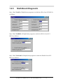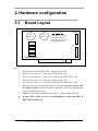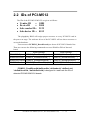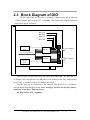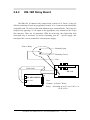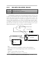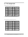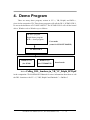
1
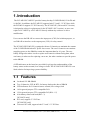
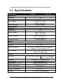
PCI-M512/M512U
User Manual
Warranty
All products manufactured by ICP DAS are warranted
against defective materials for a period of one year from the
date of delivery to the original purchaser.
Warning
ICP DAS assumes no liability for damages consequent to
the use of this product. ICP DAS reserves the right to change
this manual at any time without notice. The information
furnished by ICP DAS is believed to be accurate and reliable.
However, no responsibility is assumed by ICP DAS for its use,
or for any infringements of patents or other rights of third
parties resulting from its use.
Copyright
Copyright 2002 by ICP DAS. All rights reserved.
Trademark
The names used for identification only may be registered
trademarks of their respective companies.
PCI-M512 User Manual (Ver.2.7, Jun./2010, PMH-017-27)
----- 1
Tables of Contents
1.
INTRODUCTION................................................................................................4
1.1
FEATURES .......................................................................................................4
1.2
1.3
1.4
SPECIFICATIONS ..............................................................................................5
PRODUCT CHECK LIST ....................................................................................6
INSTALLATION QUICK START..........................................................................7
1.4.1
Software Installation..................................................................................7
1.4.2 get demo software and manual ..................................................................8
1.4.3 Hardware Installation................................................................................9
1.4.4 Hardware Diagnostic ................................................................................9
1.4.5 Multi-Board Diagnostic...........................................................................14
2.
HARDWARE CONFIGURATION .................................................................15
2.1
2.2
BOARD LAYOUT ..........................................................................................15
IDS OF PCI-M512.........................................................................................16
2.3
2.4
2.5
2.6
BLOCK DIAGRAM OF DIO .............................................................................17
BATTERY STATUS INDICATORS .....................................................................18
BLOCK DIAGRAM OF SRAM.........................................................................20
DAUGHTER BOARDS .....................................................................................21
2.6.1 DB-16P Isolated Input Board ..................................................................21
2.6.2 DB-16R Relay Board ...............................................................................22
2.6.3 DB-24PR, DB-24POR, DB-24C ..............................................................23
2.7
PIN ASSIGNMENT ..........................................................................................24
3.
DLL DRIVER.....................................................................................................25
3.0 PROGRAM ARCHITECTURE ..................................................................................26
3.1 FIND THE BOARD NUMBER..................................................................................29
3.2 FUNCTIONS OF TEST ............................................................................................30
3.2.1 PCIM512_FloatSub ....................................................................................30
3.2.2 PCIM512_ShortSub ...................................................................................30
3.2.3 PCIM512_IntSub ........................................................................................31
3.2.4 PCIM512_GetDllVersion ...........................................................................31
3.3FUNCTIONS OF DRIVER INITIALIZATION ...............................................................32
3.3.1 PCIM512_DriverInit ..................................................................................32
3.3.2 PCIM512_OpenBoard ................................................................................32
3.3.3 PCIM512_DetectBoards.............................................................................33
3.3.4 PCIM512_ReadBoardId .............................................................................34
3.3.5 PCIM512_ReadBoardStatus.......................................................................35
3.3.6 PCIM512_CloseBoard................................................................................36
PCI-M512 User Manual (Ver.2.7, Jun./2010, PMH-017-27)
----- 2
3.3.7 PCIM512_CloseAll .....................................................................................36
3.4 FUNCTIONS OF SRAM READ/WRITE.....................................................................37
3.4.1 PCIM512_WriteSramByte ..........................................................................37
3.4.2 PCIM512_WriteSramWord ........................................................................38
3.4.3 PCIM512_WriteSramDword ......................................................................39
3.4.4 PCIM512_ReadSramByte ...........................................................................40
3.4.5 PCIM512_ReadSramWord .........................................................................41
3.4.6 PCIM512_ReadSramDword .......................................................................42
3.5 FUNCTIONS OF D/I/O READ/WRITE .....................................................................43
3.5.1 PCIM512_WriteToDo.................................................................................43
3.5.2 PCIM512_ReadFromDi..............................................................................44
4. DEMO PROGRAM ..............................................................................................45
4.1 PROBLEMS REPORT .............................................................................................46
PCI-M512 User Manual (Ver.2.7, Jun./2010, PMH-017-27)
----- 3
1. Introduction
The PCI-M512/PCI-M512U provides battery-backup 512 KB SRAM, 12-bit DI and
16-bit DO. In addition, the PCI-M512U supports both 5 V and 3.3 V PCI bus, while
the PCI-M512 supports 5 V PCI bus only. The PCI-M512U (Universal PCI version)
is designed as a drop-in replacement for the PCI-M512 (PCI version), so users can
replace a PCI-M512 by a PCI-M512U directly without any software or driver
modification.
Users can use the DB-16P to connect the input ports (CN2) for isolation purpose, or
use DB-16R to interface to the output ports (CN1) for relay control.
The PCI-M512/PCI-M512U is equipped with two Li-batteries to maintain the content
of the 512 KB SRAM when PC power loss occurs. The two Li-batteries can continue
supplying power to the SRAM to retain the important data for 10 years. The twobattery design also makes it safe to replace new batteries without losing data; when
one battery is taken out for replacing a new one, the other continues to provide power
to the SRAM.
4 LED indicators on the board are provided for giving clear understanding of the
battery states such as normal, low voltage or fault. The PCI-M512/PCI-M512U is an
ideal solution for improving system reliability.
1.1 Features
z
z
z
z
z
z
z
z
On-board 512 KB SRAM
Two Li-batteries, BT1 & BT2, for battery-backup the data of SRAM
LED indicators for Li-batteries states: normal, low voltage, fault
16-bit general purpose TTL-compatible D/O
12-bit general propose TTL-compatible D/I (DI4 ~ 15)
4-bit battery status read back(DI0 ~ 3)
[PCI-M512 only]
PCI card, supports 5 V PCI bus.
[PCI-M512U only]
Universal PCI card, supports both 5 V and 3.3 V PCI bus.
PCI-M512 User Manual (Ver.2.7, Jun./2010, PMH-017-27)
----- 4
1.2 Specifications
Model Name
PCI-M512
PCI-M512U
Digital Input
Channels
12
Compatibility
5 V/TTL
Input Voltage
Logic 0: 0.8 V max.
Logic 1: 2.0 V min.
Response Speed
1.4 MHz(Typical)
Digital Output
Channels
16
Compatibility
5 V/TTL
Output Voltage
Logic 0: 0.4 V max.
Logic 1: 2.4 V min.
Output Capability
Sink: 2.4 mA @ 0.8 V
Source: 0.8 mA @ 2.0 V
Response Speed
1.4 MHz(Typical)
Special
SRAM Size
512 KB
Li-Battery
BT1 & BT2
Battery Status bits
BT1 Low, BT1 Bad, BT2 Low, BT2 Bad(low
voltage=2.3 V, bad voltage=2.1 V)
LED Indicators
BT1 Low (Green), BT1 Bad (Red) BT2 Low
(Green), BT2 Bad (Red)
General
Bus Type
5 V PCI, 32-bit, 33 MHz
Data Bus
3.3 V / 5 V Universal
PCI, 32-bit, 33 MHz
16-bit(DI/DO) ,32-bit(Memory)
I/O Connector
Dimensions (L x W x H)
Power Consumption
Male 20-bit ribbon x 2
140 mm x 90 mm x 22 mm
420 mA @ +5 V
Operating Temperature
-20 ~ 60 °C
Storage Temperature
-40 ~ 85 °C
Humidity
0 ~ 90% RH, non-condensing
PCI-M512 User Manual (Ver.2.7, Jun./2010, PMH-017-27)
----- 5
Cell Model Name
BR2032
Max. Voltage (V)
3.0
Max. Current (mA)
Type
195.0
Lithium Coin Cells
Dimensions (D x H)
7.87 mm x 1.26 mm
1.3 Product Check List
The shipping package includes the following items:
z
One PCI-M512/PCI-M512U board
z
One companion CD for software driver
z
One Quick Start Guide
It is recommended to read the Quick Start Guide first. All the necessary and essential
information are given in the Quick Start Guide as follows:
z
Where to get the software driver, demo programs and other resources.
z
How to install the software.
z
How to test the card.
Attention!
If any of these items are missing or damaged, contact the
dealer from whom you purchased the product. Save the
shipping materials and carton in case you want to ship or store
the product in the future.
PCI-M512 User Manual (Ver.2.7, Jun./2010, PMH-017-27)
----- 6
1.4 Installation Quick Start
The PCI-M512 software supports Windows 98/NT/2000/XP/2003/Vista/7/2008
32/64-bit.
1.4.1
Software Installation
Step 1: insert the companion CD into the CD-ROM driver. It will auto run as follows:
Step 2: click the first item, PCI Bus DAQ Card
Step 3: click the item, PCI-M512
PCI-M512 User Manual (Ver.2.7, Jun./2010, PMH-017-27)
----- 7
1.4.2
get demo software and manual
Now you had installed the driver and rebooted your PC. The Plug and Play had run
automatically and you see the PCI-M512 installation information in “Device
Manager”.
You also got the demo programs already. For example, after running self-extracting
archive “dll_Delphi4_yymmdd.exe”, the demo programs will show as follows:
DioSingle Æ Test DIO of the PCI-M512 (only one program can access this board)
DioSingle2Æ Test DIO of the PCI-M512
DioTest Æ Test DIO of the PCI-M512
DllTest
Æ Test DLL driver & detect the PCI-M512/M512U
---------------------------------------------------------------------------------SramTest Æ Test NVSRAM of the PCI-M512
TestDio2 Æ Write DO then read DI of two PCI-M512 boards
TestId2 Æ Show IDs of two PCI-M512 boards
TestSram2 Æ Show SRAM of two PCI-M512 boards
Get the PCI-M512 hardware manual:
The hardware manual “pcim512.pdf” is in the companion CD
CD:\NAPDOS\PCI\PCI-M512\Manual
PCI-M512 User Manual (Ver.2.7, Jun./2010, PMH-017-27)
----- 8
Get the FAQ documentation:
If you have any problem about install hardware, driver and software, please refer to
the companion CD:\NAPDOS\PCI\Manual. Those documentations include
“Software Installation Guide”, “Trouble Shooting in Win32 Resource Conflict” and
solutions of frequently asked software questions.
1.4.3
Hardware Installation
Step 1: Install your PCI-M512/M512U to PC
Step 2: Power on your PC
Step 3: Now Windows 98/2000/XP will find a PCI-M512/M512U card & ask you to
provide a software driver. Refer
to ”PCI_ISA_PnP_Driver_Installation_in_Win9x_2K_XP.pdf “ for more
information. You can find the documentation in the companion
CD:\NAPDOS\PCI\Manual
1.4.4
Hardware Diagnostic
Step 1: run DllTest of Delphi demo program as follows: (Sec. 1.4.2)
z
z
z
Click Initial Steps first to check the kernel driver, DLL & PCIM512DetectBoards()
Check that the value of PCIM512_DriverInit is 0
Click ReadBoardId to show the IDs of selected PCI-M512 in this PC
PCI-M512 User Manual (Ver.2.7, Jun./2010, PMH-017-27)
----- 9
z
Key-in new dwBoardNo to show IDs of another PCI-M512 as follows:.
Refer to Sec. 2.2 for more information about IDs of PCI-M512 as follows:
z
z
z
z
Vendor ID
Device ID
Sub-vendor ID
Sub-device ID
=
=
=
=
10B5
9050
2129
0512
PCI-M512 User Manual (Ver.2.7, Jun./2010, PMH-017-27)
----- 10
Step 2: run DioTest of Delphi demo program as follows: (Sec. 1.4.2)
z
Click Digital Output 0xDDDD to write to D/O & Read D/I as follows: (writedata is given in Digital Output Data 0xDDDD)
z
Check that lowest 4 bits are equal 0. These 4 bits are battery status bits. Refer to
Sec. 2.4 for more information.
Click Digital Output $5555 to write 0x5555 to D/O & Read D/I as follows:
z
z
Key-in new dwBoardNo to read/write to other PCI-M512.
Refer to Sec. 3.1 for more information.
PCI-M512 User Manual (Ver.2.7, Jun./2010, PMH-017-27)
----- 11
Step 3: run SramTest of Delphi demo program as follows: (Sec. 1.4.2)
z
z
z
z
Click Sram Write to write data to SRAM (offset address of SRAM is given in
R/W Offset Address, byte/word/dword read/write is given in Mode Æ
Byte/Word/Dword)
Click Sram Read to read data from SRAM (offset address of SRAM is given in
R/W Offset Address, byte/word/dword read/write is given in Mode Æ
Byte/Word/Dword)
Key-in new dwBoardNo to read/write to other PCI-M512/M512U.
Refer to Sec. 3.1 for more information.
Write 0x12345678 to offset address 0 of SRAM as follows:
PCI-M512 User Manual (Ver.2.7, Jun./2010, PMH-017-27)
----- 12
z
Read one byte of SRAM at offset address 0 as follows:
z
Read one word of SRAM at offset address 0 as follows:
z
Read one dword of SRAM at offset address 0 as follows:
PCI-M512 User Manual (Ver.2.7, Jun./2010, PMH-017-27)
----- 13
1.4.5
Multi-Board Diagnostic
Step 1: Run TestId2 of Delphi demo program to read & show IDs of two PCI-M512s
as follows:
Step 2: Run TestDIO2 of Delphi demo program to read/write D/I/O of two PCIM512s as follows:
Step 3: Run TestSram2 of Delphi demo program to read/write SRAM of two PCIM512s as follows:
PCI-M512 User Manual (Ver.2.7, Jun./2010, PMH-017-27)
----- 14
2. Hardware configuration
2.1
Board Layout
LED1 LED2 LED3 LED4
BT1
(Battery 1)
BT2
(Battery 2)
CN2(DI)
LED1: BT1 Low, Green
LED2: BT1 Bad, Red
LED3: BT2 Low, Green
LED4: BT2 Bad, Red
CN1(DO)
PCI-M512/M512U
Note:
1.
2.
3.
4.
5.
6.
7.
8.
If BT1& BT2 are both OK, LED1 ~ LED4 will be OFF.
If BT1 is lower than 2.3 V, the green LED1 will be ON.
If BT1 is lower than 2.1 V, the green LED1 & red LED2 will be ON.
If BT2 is lower than 2.3 V, the green LED3 will be ON.
If BT2 is lower than 2.1 V, the green LED3 & red LED4 will be ON.
If the PC power is off, the power control circuit will select the battery with
the higher voltage to backup SRAM. If both BT1 & BT2 are bad, the data
stored in SRAM may be lost.
SRAM can keep all stored data if either BT1 or BT2 is higher then 2 V.
If either BT1 or BT2 is bad, it is recommended to replace both BT1 &
BT2 with new batteries.
PCI-M512 User Manual (Ver.2.7, Jun./2010, PMH-017-27)
----- 15
2.2 IDs of PCI-M512
The IDs of the PCI-M512/M512U are given as follows:
•
•
•
•
Vendor ID
=
Device ID
=
Sub-vendor ID=
Sub-device ID =
10B5
9050
2129
0512
The plug&play BIOS will assign proper resources to every PCI-M512 card in
the power-on stage. The software driver of the PCI-M512 will use these resources to
access the hardware.
Users must use PCIM512_DetectBoards() to detect all PCI-M512 boards first.
Then user can use the following commands to access SRAM or DIO of detected
board.
Read Function
Write Function
SRAM R/W Byte
PCIM512_ReadSramByte(…)
PCIM512_WriteSramByte(…)
SRAM R/W Word
PCIM512_ReadSramWord(…)
PCIM512_WriteSramWord(…)
SRAM R/W DWord PCIM512_ReadSramDword(…)
PCIM512_WriteSramDword(…)
DIO R/W Word
PCIM512_WriteToDo(…)
PCIM512_ReadFrom Di(…)
PCIM512_ReadIBoardId(dwBoardNo,*dwVendorId, *dwDeviceId,
*dwSubVendorId, *dwSubDeviceId) is designed to read back the IDs of
detected PCI-M512/M512U boards.
PCI-M512 User Manual (Ver.2.7, Jun./2010, PMH-017-27)
----- 16
2.3 Block Diagram of DIO
The PCI-M512/M512U provides 16 channels of digital input and 16 channels
of digital output. All levels are TTL compatible. The connections diagram and block
diagram are given as follows:
BT1 Low
BT1 Bad
BT2 Low
BT2 Bad
CN2
D/I read
signal.
12 Channels
Di port
Local Data Bus D0..D15
16 Channels
Do port
D/O write
signal
CN1
The D/O port can be connected to the DB-16R or DB-24PR. The DB-16R is a
16-channel relay output board. The DB-24R is a 24-channel power relay output board.
(Note: Only 16 channels of these 24 channels are valid).
The D/I port can be connected to the DB-16P. The DB-16P is a 16-channel
isolated digital input daughter board. Note: starting 4 channels are used by battery
status bits as the above diagram shown.
All DI & DO are TTL compatible.
PCI-M512 User Manual (Ver.2.7, Jun./2010, PMH-017-27)
----- 17
2.4 Battery Status Indicators
LED1 LED2 LED3
(Green) (Red) (Green)
LED4
(Red)
D/I Port
2.3V
Bit0
(BT1 Low)
Bit1
(BT1 Bad)
Bit2
(BT2 Low)
Comparato
BT1
2.1V
Comparator
2.3V
Comparator
16 Channels
BT2
CPU
Bit3
2.1V
(BT2 Bad)
Comparator
CN2
12 Channels
Bit4
§
Bit15
External Digital
PCI-M512 User Manual (Ver.2.7, Jun./2010, PMH-017-27)
----- 18
The initial voltage of BT1 will be larger then 3.0 V. If this voltage drops to 2.3
V, BT1 can still keep the stored data in SRAM for months. It is recommended to
replace both BT1 & BT2 when either BT1 or BT2 drops to 2.3 V. If this voltage
drops to 2.1 V, the BT1 can still keep the stored data in SRAM for weeks. You
should replace both BT1 & BT2 a.s.a.p. if either BT1 or BT2 drops to 2.1 V.
The action table is given as follows:
Battery voltage status
LED status
D/I port status
BT1 > 2.3 V
LED1 OFF, LED2 OFF
Bit0=0, Bit1=0
2.3 V>BT1>2.1 V
LED1 ON, LED2 OFF
Bit0=1, Bit1=0
2.1 V>BT1
LED1 ON, LED2 ON
Bit0=1, Bit1=1
BT2 > 2.3 V
LED3 OFF, LED4 OFF
Bit2=0, Bit3=0
2.3 V>BT2>2.1 V
LED3 ON, LED4 OFF
Bit2=1, Bit3=0
2.1 V>BT2
LED3 ON, LED4 ON
Bit2=1, Bit3=1
You can call PCIM512_ReadFromDi(DWORD dwBoardNo, WORD *Data) to
read the 16-bit data. Refer to Sec. 3.6 for more information.
The lowest 4 bits, Bit0 ~ Bit3, are battery status bits. The
other 12 bits, Bit4 ~ Bit15, are external D/I signals. You can
connect a DB-16P to CN2 for sensor input. Refer to Sec. 2.5.1 for
more information.
If you find that either BT1 or BT2 is in low-battery state, it is recommended to
replace both BT1 & BT2 as follows:
1. Prepare 2 new batteries for new BT1 & new BT2
2.
3.
4.
Power on PC (not power off)
Replace the old BT1 with the new BT1
Replace the old BT2 with the new BT2
Note: it is recommended to replace both BT1 & BT2 at the same time, one by one.
The two-battery design also makes it safe to replace new batteries without losing data;
when one battery is taken out for replacing a new one, the other continues to provide
power to the SRAM.
PCI-M512 User Manual (Ver.2.7, Jun./2010, PMH-017-27)
----- 19
2.5 Block Diagram of SRAM
R/W to SRAM
Comparator
Enable
4.5V
Chip Enable
VCC of PC
Comparator
VCC
BT1
Comparator
BT2
Select the most higher
Select the most higher
SRAM IC.
The power supply of SRAM is selected from the highest voltage of PC-VCC,
BT1 & BT2. The initial voltage of BT1 & BT2 is about 3 V. If the PC is power on,
the PC-VCC will be about 5 V. If the PC is off, the PC-VCC will be about 0 V. So
when the PC is power on, the PC-VCC will supply power to SRAM. In this condition,
BT1 & BT2 will preserve their battery for later usage.
If PC’s power is off, the battery with higher voltage will supply power to
SRAM. The stored data of SRAM will remain if the power is larger than 2.0 V. So,
either BT1 or BT2 must higher than 2.0 V to keep the SRAM data.
There is one low-battery indicator & one bad-battery indicator for both BT1 &
BT2. Refer to Sec. 2.3 for more information.
PCI-M512 User Manual (Ver.2.7, Jun./2010, PMH-017-27)
----- 20
2.6 Daughter Boards
2.6.1
DB-16P Isolated Input Board
The DB-16P is a 16-channel isolated digital input daughter board. The optically
isolated inputs of the DB-16P consist of a bi-directional optocoupler with a resistor
for current sensing. You can use the DB-16P to sense DC signal from TTL levels up
to 24 V or use the DB-16P to sense a wide range of AC signals. You can use this
board to isolate the computer from large common-mode voltage, ground loops and
transient voltage spike that often occur in industrial environments. Note: The lowest
nibbles, bit_0 to bit_3, are used by PCI-M512, so only the highest 12-bits, bit_4
to bit_15, are available.
V+
D/I-4 ~ 15 of PCI-M512
VOpto-Isolated
CN2=D/I
PCI-M512/M512U
20Pin cable
DB-16P
AC or DC Signal
0 V to 24 V
PCI-M512 User Manual (Ver.2.7, Jun./2010, PMH-017-27)
----- 21
2.6.2
DB-16R Relay Board
The DB-16R, 16-channel relay output board, consists of 16 Form C relays for
efficient switching of loads by programmed control. It is a connector and functionally
compatible with 785 series boards with industrial type terminal blocks. The relays are
energized by applying a 5 volt signal to the appropriate relay channel on the 20-pin
flat connector. There are 16 enunciator LEDs for each relay, they light when their
associated relay is activated. To avoid overloading your PC's power supply, this
board provides a screw terminal for external power supply.
Form C Relay
Normally Open
Normally Closed
Com.
20Pin cable
DB-16R
PCI-M512/M512U
CN1=D/O
Note:
Channel : 16 Form C Relay
Relay : Switching up to 0.5 A at 110 VAC or
1 A at 24 VDC
PCI-M512 User Manual (Ver.2.7, Jun./2010, PMH-017-27)
----- 22
2.6.3
DB-24PR, DB-24POR, DB-24C
DB-24PR
24*power relay, 5 A/250 V
DB-24POR
24*photo MOS relay, 0.1 A/350 VAC
DB-24C
24*open collector, 100 mA per channel, 30 V max.
The DB-24PR, 24-channel power relay output board, consists of 8 Form C and
16 Form A electromechanical relays for efficient switching of loads by programmed
control. The contact of each relay can control a 5 A load at 250 VAC/30 VDC. The
relay is energized by applying a 5 volt signal to the appropriate relay channel on the
20-pin flat cable connector(just uses 16 relays) or 50-pin flat cable connector.(OPTO22 compatible, for DIO-24 series). Twenty - four enunciator LEDs, one for each relay,
light when their associated relay is activated. To avoid overloading your PC’s power
supply, this board needs a +12 VDC or +24 VDC external power supply.
Normal Open
Form A Relay
Com.
20Pin cable
To 20pin connector
DB-24PR
PCI-M512/M512U
CN1=D/O
Note:
50-Pin connector(OPTO-22 compatible), for DIO-24, DIO-48, DIO-144
20-Pin connector for 16 channel digital output, A-82X, A-62X, DIO-64, ISODA16/DA8
Channel : 16 From A Relay , 8 From C Relay
Relay : switching up to 5 A at 110 VAC / 5 A at 30 VDC
PCI-M512 User Manual (Ver.2.7, Jun./2010, PMH-017-27)
----- 23
2.7 Pin Assignment
CN2: pin assignment of digital input connector.
Pin
Name
Pin
Name
1
3
-
2
4
-
5
Digital input 4
6
Digital input 5
17
Digital input 6
8
Digital input 7
9
Digital input 8
10
Digital input 9
11
Digital input 10
12
Digital input 11
13
Digital input 12
14
Digital input 13
15
Digital input 14
16
Digital input 15
17
PCB ground
18
PCB ground
19
PCB +5 V
20
PCB +12 V
Note: The DI 0 ~ 3 are reserved for internal batteries status.
CN1: pin assignment of the digital output connector.
Pin
Name
Pin
Name
1
Digital output 0
2
Digital output 1
3
Digital output 2
4
Digital output 3
5
Digital output 4
6
Digital output 5
17
Digital output 6
8
Digital output 7
9
Digital output 8
10
Digital output 9
11
Digital output 10
12
Digital output 11
13
Digital output 12
14
Digital output 13
15
Digital output 14
16
Digital output 15
17
PCB ground
18
PCB ground
19
PCB +5 V
20
PCB +12 V
PCI-M512 User Manual (Ver.2.7, Jun./2010, PMH-017-27)
----- 24
3. DLL Driver
The included software is a collection of subroutines for PCI-M512/M512U
cards for Windows 95/98/NT/2000/XP applications. These subroutines are written
with C language and perform a variety of digital I/O operations.
The subroutines in PCIM512.DLL are easy to understand as its name suggests
for. It provides powerful, easy-to-use subroutines for developing your data
acquisition application. Your program can easily call these DLL functions by VC++
VB, Delphi, and BORLAND C++ Builder. To speed-up your developing process,
some demonstration source programs are provided.
Please refer to the following user manuals, you could fine them in the companion
CD:\NAPDOS\PCI\Manual.
• PCI_ISA_PnP_Driver_Installation_in_Win9x_2K_XP.pdf
Install the PnP (Plug and Play) driver for PCI card under Windows 95/98.
• Software_Installation_Guide_in_Win32.pdf
Install the software package under Windows 95/98/NT/XP.
• Calling_DLL_functions_in_VB_VC_Delphi_BCB.pdf
Call the DLL functions with VC++6, VB6, Delphi3 and
Borland C++ Builder 3.
•
TroubleShooting_PCI_ISA_in_Win32_Resource_Conflict.pdf
Check the resources I/O Port address, IRQ number and DMA number for
add-on cards under Windows 95/98/NT.
PCI-M512 User Manual (Ver.2.7, Jun./2010, PMH-017-27)
----- 25
3.0 Program Architecture
Initialize the Kernel Driver
PCIM512_DriverInit()
PCIM512_DetectCards()
….
….
PCIM512_ReadSramDword(…)
……..
……..
PCIM512_WriteSramDword(…)
…..
Detect PCI-M512
Access the SRAM/DI/DO
Access the SRAM/DI/DO
PCIM512_DriverClose()
Close the Device-Driver
User's Application
Function Call into DLLs
Development
Toolkit
DLLs
Services Call into Kernel-Mode
.VXDs, .SYSs (Device Driver)
Device Control
Hardware Devices
PCI-M512 User Manual (Ver.2.7, Jun./2010, PMH-017-27)
----- 26
In this chapter, we use some keywords to indicate the attribute of Parameters.
Keyword
Set parameter by user
before calling this function ?
Get the data/value from this
parameter after calling this
function ?
[Input]
Yes
No
[Output]
No
Yes
[Input, Output]
Yes
Yes
Note: All space of the parameters needs to be allocated first by user’s
program.
The return codes of DLL are defined as follows:
// return code
#define PCI_NoError
0
#define PCI_DriverOpenError
1
#define PCI_DriverNoOpen
2
#define PCI_GetDriverVersionError
3
#define PCI_InstallIrqError
4
#define PCI_ClearIntCountError
5
#define PCI_GetIntCountError
6
#define PCI_RegisterApcError
7
#define PCI_RemoveIrqError
8
#define PCI_FindBoardError
9
#define PCI_ExceedBoardNumber
10
#define PCI_ResetError
11
#define PCI_IrqMaskError
12
#define PCI_ActiveModeError
13
#define PCI_GetActiveFlagError
14
#define PCI_ActiveFlagEndOfQueue
15
#define PCI_BoardNoIsZero
16
#define PCI_BoardNoExceedFindBoards
17
PCI-M512 User Manual (Ver.2.7, Jun./2010, PMH-017-27)
----- 27
The defined DLL functions are given as follows:
Functions of test, Refer to Sec. 3.2
z float
CALLBACK PCIM512_FloatSub(float fA, float fB);
z short
CALLBACK PCIM512_ShortSub(short nA, short nB);
z int
CALLBACK PCIM512_IntSub(int iA,int iB);
z DWORD CALLBACK PCIM512_GetDllVersion(void);
Functions of Driver Initialization, Refer to Sec. 3.3
z DWORD CALLBACK PCIM512_DriverInit(void);
z DWORD CALLBACK PCIM512_CloseBoard(DWORD dwBoardNo);
z DWORD CALLBACK PCIM512_DetectBoards(void);
z DWORD CALLBACK PCIM512_OpenBoard(DWORD dwBoardNo, DWORD
dwIntEnable);
z DWORD CALLBACK PCIM512_ReadBoardStatus(DWORD dwBoardNo);
z DWORD CALLBACK PCIM512_CloseAll(void);
Functions of SRAM Read/Write, Refer to Sec. 3.4
z DWORD
CALLBACK PCIM512_WriteSramByte(DWORD dwBoardNo,
DWORD dwOffset, BYTE Data);
z DWORD
CALLBACK PCIM512_WriteSramWord(DWORD dwBoardNo,
DWORD dwOffset, WORD Data);
z DWORD
CALLBACK PCIM512_WriteSramDword(DWORD dwBoardNo,
DWORD dwOffset, DWORD Data);
z DWORD
CALLBACK PCIM512_ReadSramByte(DWORD dwBoardNo,
DWORD dwOffset, BYTE *Data);
z DWORD
CALLBACK PCIM512_ReadSramWord(DWORD dwBoardNo,
DWORD dwOffset, WORD *Data);
z DWORD
CALLBACK PCIM512_ReadSramDword(DWORD dwBoardNo,
DWORD dwOffset, DWORD *Data);
Functions of DIO Read/Write, Refer to Sec. 3.5
z DWORD
CALLBACK PCIM512_WriteToDo(DWORD
WORD Data);
z DWORD
CALLBACK PCIM512_ReadFromDi(DWORD
WORD *Data);
PCI-M512 User Manual (Ver.2.7, Jun./2010, PMH-017-27)
dwBoardNo,
----- 28
dwBoardNo,
3.1 Find the Board Number
The plug&play BIOS will assign the proper base address to PCI-M512/M512U.
If there is only one PCI-M512, users can identify this board as board_1. If there are
two PCI-M512 boards in the system, it will be very difficult to identify which board
is board_1. Our software driver can support 20 boards max. Therefore user can
install 20 boards of PCI-M512 in one PC system.
The simplest way to find the board number is to use DioTest in Delphi4
demo program. This demo program will send a value to D/O and read back from
D/I. The low 4 bits of D/I are battery status bits, they can be used as an indicator as
follows:
Insert one piece of paper to BT1 of one PCI-M512
Install all PCI-M512 cards into this PC system
Power-on PC
You will find only one PCI-M512’s LED1 & LED2 are ON
Run DioTest of Delphi4
Key-in board number to 1
Click Digital Output 0xDD
Check the value in Digital Input, if the LSB is 1, we find the target PCI-M512.
DioTest
PCI-M512 User Manual (Ver.2.7, Jun./2010, PMH-017-27)
----- 29
3.2 Functions of Test
3.2.1 PCIM512_FloatSub
• Description:
To perform the subtraction as fA - fB in float data type. This function is
provided for testing DLL linkage purpose.
•
•
•
Syntax:
float PCIM512_FloatSub(float fA, float fB)
Parameter:
fA
: [Input] 4 bytes floating point value
fB
: [Input] 4 bytes floating point value
Return:
The value of fA - fB
3.2.2 PCIM512_ShortSub
•
•
•
•
Description:
To perform the subtraction as nA - nB in short data type. This function is
provided for testing DLL linkage purpose.
Syntax:
short PCIM512_ShortSub(short nA, short nB)
Parameter:
nA
:[Input] 2 bytes short data type value
nB
:[Input] 2 bytes short data type value
Return:
The value of nA – nB.
PCI-M512 User Manual (Ver.2.7, Jun./2010, PMH-017-27)
----- 30
3.2.3 PCIM512_IntSub
• Description:
To perform the subtraction as iA - iB in int data type. This function is
provided for testing DLL linkage purpose.
•
•
•
Syntax:
short PCIM512_IntSub(int iA, int iB)
Parameter:
iA
:[Input] 4 bytes int data type value
iB
:[Input] 4 bytes int data type value
Return:
The value of iA – iB
3.2.4 PCIM512_GetDllVersion
•
•
•
•
Description:
To get the version number of PCIM512.DLL
Syntax:
DWORD PCIM512_GetDllVersion(void)
Parameter:
None
Return:
Return the DLL’s version number.
For example: 102(hex) for version 1.02
PCI-M512 User Manual (Ver.2.7, Jun./2010, PMH-017-27)
----- 31
3.3Functions of Driver Initialization
3.3.1 PCIM512_DriverInit
• Description :
This subroutine will allocate resources for the WinDriver. This function must
be called before using the DLL functions given in Sec 3.3 ~ Sec. 3.5.
•
•
•
Syntax :
DWORD PCIM512_DriverInit();
Parameter :
None
Return:
PCI_NoError
: OK
PCI_DriverOpenError: WinDriver kernel not find, refer to Sec. 1.2.1 for
more information.
3.3.2 PCIM512_OpenBoard
• Description :
This subroutine will open the PCI-M512 kernel driver and allocate
resource for the device. This function must be called before using other
I/O functions
•
•
•
Syntax :
void PCIM512_OpenBoard(DWORD dwBoardNo, DWORD dwIntEnable);
Parameter :
dwBoardNo
dwIntEnable
[Input] PCI-M512 board number
[Input] PCI-M512 board interrupt enable/disable(1/0)
Return:
PCI_NoError
: OK
PCI_BoardOpenError
: Board open kernel driver error
PCI_BoardNoExceedFindBoards
: Not find the Board.
PCI-M512 User Manual (Ver.2.7, Jun./2010, PMH-017-27)
----- 32
3.3.3 PCIM512_DetectBoards
• Description :
This subroutine will detect all installed PCI-M512/M512U boards. This
function must be called before using other I/O functions given in Sec
3.4 & Sec. 3.5.
•
•
•
•
Syntax :
DWORD PCIM512_DetectBoards();
Parameter :
None
Return:
0: No PCI-M512 is installed in this PC
1: Only one PCI-M512/M512U is installed in this PC(board no.=1)
2: There are 2 PCI-M512/M512U installed in this PC(board no.=1/2)
N: Number of PCI-M512 installed in this PC
Note:
1. Call PCIM512_DriverInit() before calling this function
2. Call PCIM512_OpenBoard() before calling this function
3. Call PCIM512_DetectBoards() to detect all PCI-M512 boards.
4. Call PCIM512_ReadBoardId(…) to identify the detected PCI-M512
boards. Refer to Sec. 2.2 for more information.
PCI-M512 User Manual (Ver.2.7, Jun./2010, PMH-017-27)
----- 33
3.3.4 PCIM512_ReadBoardId
• Description :
This subroutine will show the IDs of detected PCI-M512/M512U boards. It is
designed to identify PCI-M512/M512U.
•
•
•
•
Syntax :
DWORD PCIM512_ReadBoardId(dwBoardNo, *dwVendorId, *dwDeviceId,
*dwSubVendorId, *dwSubdeviceId);
Parameter :
dwBoardNo
dwVendorID
: [Input] PCI-M512/M512U board number(start from 1)
: [output] vendor ID of this board
dwDeviceID
dwSubVendorID
dwSubDeviceID
: [output] device ID of this board
: [output] sub-vendor ID of this board
: [output] sub-device ID of this board
Return:
0: This is a valid board no. Æ All return IDs are valid
Others: This is not a valid board no. Æ All return IDs are invalid
Note:
1. Call PCIM512_DriverInit() before calling this function
2. Call PCIM512_OpenBoard() before calling this function
3. Call PCIM512_DetectBoards() to detect all PCI-M512 boards.
4. Call PCIM512_ReadBoardId(…) to identify the detected PCIM512/M512U boards. Refer to Sec. 2.2 for more information.
PCI-M512 User Manual (Ver.2.7, Jun./2010, PMH-017-27)
----- 34
3.3.5 PCIM512_ReadBoardStatus
• Description :
This subroutine will detect the DLL open status of PCI-M512/M512U boards.
•
•
•
Syntax :
DWORD PCIM512_ReadBoardStatus(DWORD dwBoardNo);
Parameter :
dwBoardNo
[Input] PCI-M512/M512U board number
Return:
0: The DLL of the board dwBoardNo is not opened.
1: The DLL of the board dwBoardNo is opened.
•
Note:
1.
Call PCIM512_DriverInit() before calling this function
PCI-M512 User Manual (Ver.2.7, Jun./2010, PMH-017-27)
----- 35
3.3.6 PCIM512_CloseBoard
• Description :
This subroutine will close the PCI-M512/M512U kernel driver and release
the resource for the device.
•
•
•
Syntax :
DWORD PCIM512_CloseBoard(DWORD dwBoardNo);
Parameter :
dwBoardNo
[Input] PCI-M512/M512U board number
Return:
PCI_NoError :
OK.
PCI_BoardIsNotOpen:
This board is not opened.
PCI_BoardNoExceedFindBoards
Not fined the board
3.3.7 PCIM512_CloseAll
• Description :
This subroutine will close all of PCI-M512/M512U kernel driver and release
the resource for the device.
•
•
•
Syntax :
DWORD PCIM512_CloseAll();
Parameter :
None
Return:
PCI_NoError :
OK.
PCI-M512 User Manual (Ver.2.7, Jun./2010, PMH-017-27)
----- 36
3.4 Functions of Sram Read/Write
3.4.1 PCIM512_WriteSramByte
• Description:
Write one byte, 8-bit data to SRAM of PCI-M512/M512U.
•
•
•
•
Syntax:
DWORD PCIM512_WriteSramByte(dwBoardNo, dwOffset, Data)
Parameter:
dwBoardNo
: [Input] board number, from 1 to N
dwOffset
Data
: [Input] offset address of SRAM, from 0 to 0x7ffff
: [Input] one byte of data (8-bit)
Return:
0:
Write OK
PCI_DriverNoOpen:
Kernel driver not found
PCI_BoardNoIsZero: dwBoardNo is 0, it must be in the range of 1 ~ N
PCI_BoardNoExceedFindBoards: dwBoardNo > N
Note:
1. Call PCIM512_DetectBoards() before calling this function
2. Call PCIM512_ReadBoardId(…) to identify the detected PCIM512/M512U boards. Refer to Sec. 2.2 for more information.
PCI-M512 User Manual (Ver.2.7, Jun./2010, PMH-017-27)
----- 37
3.4.2 PCIM512_WriteSramWord
• Description:
Write one word, 16-bit, of data to SRAM of PCI-M512/M512U.
•
•
•
•
Syntax:
DWORD PCIM512_WriteSramWord(dwBoardNo, dwOffset, Data)
Parameter:
dwBoardNo
dwOffset
Data
: [Input] Board number, from 1 to N
: [Input] Offset address of SRAM, from 0 to 0x7fffe
: [Input] One word of data (16-bit)
Return:
0:
Write OK
PCI_DriverNoOpen:
Kernel driver not found
PCI_BoardNoIsZero: dwBoardNo is 0, it must be in the range of 1 ~ N
PCI_BoardNoExceedFindBoards: dwBoardNo > N
Note:
1. Call PCIM512_DetectBoards() before calling this function
2. Call PCIM512_ReadBoardId(…) to identify the detected PCIM512/M512U boards. Refer to Sec. 2.2 for more information.
PCI-M512 User Manual (Ver.2.7, Jun./2010, PMH-017-27)
----- 38
3.4.3 PCIM512_WriteSramDword
• Description:
Write one dword, 32-bit data to SRAM of PCI-M512/M512U.
•
•
•
•
Syntax:
DWORD PCIM512_WriteSramDword(dwBoardNo, dwOffset, Data)
Parameter:
dwBoardNo
dwOffset
Data
: [Input] Board number, from 1 to N
: [Input] Offset address of SRAM, from 0 to 0x7fffc
: [Input] One dword of data (32-bit)
Return:
0:
Write OK
PCI_DriverNoOpen:
Kernel driver not found
PCI_BoardNoIsZero: dwBoardNo is 0, it must be in the range of 1 ~ N
PCI_BoardNoExceedFindBoards: dwBoardNo > N
Note:
1. Call PCIM512_DetectBoards() before calling this function
2. Call PCIM512_ReadBoardId(…) to identify the detected PCIM512/M512U boards. Refer to Sec. 2.2 for more information.
PCI-M512 User Manual (Ver.2.7, Jun./2010, PMH-017-27)
----- 39
3.4.4 PCIM512_ReadSramByte
• Description:
Read one byte, 8-bit data from SRAM of PCI-M512/M512U.
•
•
•
•
Syntax:
DWORD PCIM512_ReadSramByte(dwBoardNo, dwOffset, *Data)
Parameter:
dwBoardNo
dwOffset
Data
: [Input] Board number, from 1 to N
: [Input] Offset address of SRAM, from 0 to 0x7ffff
: [output] One byte of data (8-bit)
Return:
0:
Write OK
PCI_DriverNoOpen:
Kernel driver not found
PCI_BoardNoIsZero: dwBoardNo is 0, it must be in the range of 1 ~ N
PCI_BoardNoExceedFindBoards: dwBoardNo > N
Note:
1. Call PCIM512_DetectBoard() before calling this function
2. Call PCIM512_ReadBoardId(…) to identify the detected PCIM512/M512U boards. Refer to Sec. 2.2 for more information.
PCI-M512 User Manual (Ver.2.7, Jun./2010, PMH-017-27)
----- 40
3.4.5 PCIM512_ReadSramWord
• Description:
Read one word, 16-bit data from SRAM of PCI-M512/M512U.
•
•
•
•
Syntax:
DWORD PCIM512_ReadSramWord(dwBoardNo, dwOffset, *Data)
Parameter:
dwBoardNo
dwOffset
Data
: [Input] Board number, from 1 to N
: [Input] Offset address of SRAM, from 0 to 0x7fffe
: [output] One word of data (16-bit)
Return:
0:
Write OK
PCI_DriverNoOpen:
Kernel driver not found
PCI_BoardNoIsZero: dwBoardNo is 0, it must be in the range of 1 ~ N
PCI_BoardNoExceedFindBoards: dwBoardNo > N
Note:
1. Call PCIM512_DetectBoards() before calling this function
2. Call PCIM512_ReadBoardId(…) to identify the detected PCIM512/M512U boards. Refer to Sec. 2.2 for more information.
PCI-M512 User Manual (Ver.2.7, Jun./2010, PMH-017-27)
----- 41
3.4.6 PCIM512_ReadSramDword
• Description:
Read one dword, 32-bit data from SRAM of PCI-M512/M512U.
•
•
•
•
Syntax:
DWORD PCIM512_ReadSramDword(dwBoardNo, dwOffset, *Data)
Parameter:
dwBoardNo
dwOffset
Data
: [Input] Board number, from 1 to N
: [Input] Offset address of SRAM, from 0 to 0x7fffc
: [output] One dword of data (32-bit)
Return:
0:
Write OK
PCI_DriverNoOpen:
Kernel driver not found
PCI_BoardNoIsZero: dwBoardNo is 0, it must be in the range of 1 ~ N
PCI_BoardNoExceedFindBoards: dwBoardNo > N
Note:
1. Call PCIM512_DetectBoards() before calling this function
2. Call PCIM512_ReadBoardId(…) to identify the detected PCIM512/M512U boards. Refer to Sec. 2.2 for more information.
PCI-M512 User Manual (Ver.2.7, Jun./2010, PMH-017-27)
----- 42
3.5 Functions of D/I/O Read/Write
3.5.1 PCIM512_WriteToDo
• Description:
Write one word, 16-bit, of data to D/O of PCI-M512/M512U.
•
•
•
•
Syntax:
DWORD PCIM512_WriteToDo(dwBoardNo, Data)
Parameter:
dwBoardNo
: [Input] Board number, from 1 to N
Data
: [Input] One word of data (16-bit)
Return:
0:
Write OK
PCI_DriverNoOpen:
Kernel driver no found
PCI_BoardNoIsZero: dwBoardNo is 0, it must be in the range of 1 ~ N
PCI_BoardNoExceedFindBoards: dwBoardNo > N
Note:
1. Call PCIM512_DetectBoards() before calling this function
2. Call PCIM512_ReadBoardId(…) to identify the detected PCI-M512
/M512U boards. Refer to Sec. 2.2 for more information.
PCI-M512 User Manual (Ver.2.7, Jun./2010, PMH-017-27)
----- 43
3.5.2 PCIM512_ReadFromDi
• Description:
Read one word, 16-bit, of data from D/I & battery status bits of PCIM512/M512U.
•
•
Syntax:
DWORD PCIM512_ReadFromDi(dwBoardNo, *Data)
Parameter:
dwBoardNo
Data:
: [Input] Board number, from 1 to N
[output] One word of data (16-bit), Bit0 ~ Bit3 are battery
status bits and Bit4 ~ Bit15 are external D/I bits as
follows:
Bit0=1 Æ BT1 is low battery
Bit1=1 Æ BT1 is bad battery
Bit2=1 Æ BT2 is low battery
Bit3=1 Æ BT3 is bad battery
(refer to Sec. S.4 for more information)
•
•
Return:
0:
Write OK
PCI_DriverNoOpen:
Kernel driver not found
PCI_BoardNoIsZero: dwBoardNo is 0, it must be in the range of 1 ~ N
PCI_BoardNoExceedFindBoards: dwBoardNo > N
Note:
1. Call PCIM512_DetectBoards() before calling this function
2. Call PCIM512_ReadBoardId(…) to identify the detected PCIM512/M512U boards. Refer to Sec. 2.2 for more information.
PCI-M512 User Manual (Ver.2.7, Jun./2010, PMH-017-27)
----- 44
4. Demo Program
There are many demo program, written in VC++, VB, Delphi, and BCB++,
given in the companion CD. These demo programs will call the DLL, PCIM512.DLL,
to access the hardware of PCI-M512/M512U. The PCIM512.DLL will call the kernel
driver, Windrvr.vxd or Windrvr.sys as follows:
VB demo program
Delphi demo program
BCB++ demo program
User mode
(same for 95/98/NT/2000XP)
PCIM512.DLL
Windrvr.vxd
(for 95/98)
Windrvr.sys
(for NT/2000/XP)
kernel mode
Refer to Calling_DLL_functions_in_VB_VC_Delphi_BCB.pdf
in the companion CD:\NAPDOS\PCI\Manual for more information about how to call
the DLL functions with VC++5, VB5, Delphi3 and Borland C++ Builder 3
PCI-M512 User Manual (Ver.2.7, Jun./2010, PMH-017-27)
----- 45
.
4.1 Problems Report
Technical support is available at no charge as described below. The
best way to report problems is to send electronic mail to
[email protected]
When reporting problems, please include the following information:
1) Is the problem reproducible? If so, how?
2) What kind and version of platform that you using? For example,
Windows 3.1, Windows 95, or Windows NT 4.0, etc.
3) What kinds of our products are you using? Please see the product's
manual.
4) If a dialog box with an error message was displayed, please include
the full text of the dialog box, including the text in the title bar.
5) If the problem involves other programs or hardware devices, what
devices or version of the failing programs are you using?
6) Other comments relative to this problem or any suggestions will be
welcomed.
After we had received your comments, we will take about two
business days to test the problems that you reported. Then will reply as
soon as possible to you. Please keep in contact with us.
ICP DAS
E-mail: [email protected]
Web Site: http://www.icpdas.com
PCI-M512 User Manual (Ver.2.7, Jun./2010, PMH-017-27)
----- 46