1
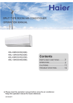
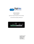
MV2A User’s Guide
Televac...The Finest In Vacuum Instrumentation
Instrument Part No. 2-7900-071
Some Thoughts From Televac
Thank you for purchasing the MV2A Thermocouple Vacuum Instrument. The MV2A is a unique
and rugged power supply, controller and display device for Televac type 2A thermocouple vacuum
sensors. It is easy to use and will provide you with many years of trouble-free service. This manual
is designed to help MV2A users gain the greatest benefit from the instrument’s use. Please review
the manual before attempting to operate the instrument.
1.0 Unpacking & Inspection
Inventory the Contents: Compare the list of items from your original purchase documents against
the items listed on our shipping documents. Compare these against the actual contents of the
shipping container. Report any differences to Televac.
Damage: In the unlikely event that the shipping container was damaged in transit, carefully inspect
the contents for damage. If the MV2A Instrument or any of its accessories were damaged in
transit, contact the freight carrier and tell them you wish to make a damage claim. Contact Televac
for further instructions on replacement of damaged materials.
If the shipment arrived in good order, proceed to step 2.0
2.0 Wiring and Initial Start-Up Reference to figure 1
Your MV2A was factory tested, calibrated and met Televac’s high quality standards. No further
adjustment of the instrument is necessary.
Begin by connecting the optional cable between your Televac type 2A thermocouple sensor and
the modular cable port on the rear of the instrument. The instrument cable port is labeled ‘input’.
Televac has supplied you with the mating connectors for the Setpoint and Analog Output (REC
OUT) ports. If you plan to use these features, please wire the connectors to your external devices
now. Refer to Specifications section of this User’s Guide for further information on these features,
We recommend a dedicated ground wire be connected between a known ground point in your
facility and the ground screw designated with the universal ground symbol on the rear of the
instrument.
Connect the supplied 115 VAC power cable to its port on the rear of the instrument. There is no
power switch. The instrument will automatically power-up. Proceed to step 3.0
Figure 1
Page 2
3.0 Checking Pressure and Adjusting Setpoints - Reference to Figure 2
The instrument should now be measuring and diaplaying a pressure (presuming the instrument is
properly cabled to a functioning type 2A sensor and the pressure is within the sensor’s range - i.e.
between 20 torr and 1 millitorr [20,000 microns and 1 micron]).
The instrument is equipped with dual setpoints which are adjustable from the front panel. To adjust
the setpoint value •
Press the button labeled SP#1. The previously stored setpoint will be displayed.
•
Continue pressing SP#1 and now press either the ‘Up’ or ‘Down’ button to increase or
decrease the value of the setpoint until the desired value is displayed.
•
Releasing the SP#1 button will overwrite the old value and store the new value in memory.
Repeat this process with the SP#2 button if a second setpoint is needed.
Setpoint Selector Buttons
Setpoint Value Adjustment Buttons
Figure 2
Note: Factory settings can be restored by pressing the SP#1, SP#2, Up and Down buttons simultaneously.
The setpoints will be established at 100 and 200 millitorr.
4.0 Analog Output
A 0-5VDC analog output port is provided at the rear of the instrument. The output voltage is linear
and proportional to pressure between 1000 and 0 millitorr, per the following table.
MILLITORR
0
1
5
10
20
30
40
50
60
70
80
90
100
VOLTAGE
0.000
0.005
0.025
0.050
0.100
0.150
0.200
0.250
0.300
0.350
0.400
0.450
0.500
MILLITORR
200
300
400
500
600
700
800
900
1000
Page 3
VOLTAGE
1.000
1.500
2.000
2.500
3.000
3.500
4.000
4.500
5.000
5.0 User Calibration of the MV2A
Under normal operating conditions, the user may wish to calibrate the MV2A once or twice per
year. This procedure simple to perform, and two optional methods are given. One method requires
the use of a Televac Reference Standard (2A Simulator) while the other uses a 2A sensor. Refer to
Recommended Options and Spares section of this manual for details.
Procedure A - Using Reference Standard to achieve a three point calibration
•
Attach the Reference Standard to the end of the sensor cable in place of the 2A sensor
and set the Reference Standard’s selector to ‘0’.
•
Power the instrument from a 110VAC source.
•
Press and simultaneously hold both SP#1 and SP#2 buttons to enable adjustment. While
holding the SP buttons, press the Up or Down buttons until a ‘0’ reading is achieved.
•
Repeat this procedure using the 100 and 1000 millitorr selector positions on the Reference
Standard.
Procedure B - Using a 2A sensor to achieve a two point calibration
•
With the MV2A powered up and attached to a 2A sensor, reduce the vacuum system’s
pressure to at least one decade of pressure less than the sensor will read - i.e. 0.1 millitorr.
•
Press and simultaneously hold both SP#1 and SP#2 buttons to enable adjustment. While
holding the SP buttons, press the Up or Down buttons until a ‘0’ reading is achieved.
•
Increase the vacuum system pressure to 800 millitorr.
•
Press and simultaneously hold both SP#1 and SP#2 buttons to enable adjustment. While
holding the SP buttons, press the Up or Down buttons until a ‘800’ is displayed.
Page 4
6.0 Useful Information
6.1 Vacuum Terminology and The MV2A:
Atmospheric pressure is defined at 760 torr (at sea level, when the barometric pressure is 29.92”
Hg).
One Torr is 1/760 of atmospheric pressure. One Torr can also be expressed as 1000 Millitorr or
1000 Microns.
One Millitorr or one Micron is 1/760,000 of atmospheric pressure.
The thermocouple sensors that are used with your MV2A instrument are designed to measure a
small portion of that wide band of reduced pressure that extends from atmospheric pressure to a
region known as very ultrahigh vacuum (~ 1x10-14 torr). This total spectrum of measurable vacuum
contains about 18 decades of pressure.
For example:
The Televac 2A series sensor measures from 20 torr to 1 millitorr. Five decades.
Please realize that the smaller the dynamic range of the sensor, the less visibility the user has to
pressure changes.
6.2 Practical issues to consider with thermocouple sensors:
√
The most common failure mechanism is gross contamination. If there is a probable risk of
contamination by particulate or liquids, we recommend the use of one of our sensor filters.
√
Vertical orientation with electrical pins ‘up’ (where practical) is usually preferred to inverted
or horizontal orientation.
√
If your application requires a sensor that’s immune to shock, vibration, excessive heat and/
or severe weather conditions, contact us for information on our family of Miniature 2A sensors.
√
It is usually useful to have a known reference to periodically check the instrument and/or
sensor performance. Refer to the informationon the next page about our inexpensive reference
standards.
6.3 Contacting us:
Our main telephone number is 215-938-4444 and our normal hours are 8:00am to 5:00pm eastern
time.
Our fax number is 215-947-7464.
Our main email address is [email protected]
You can locate the name and contact information of your local Televac representative through our
website - www.televac.com.
Page 5
7.0 Troubleshooting
7.1 No Digital Display -
Power Cable is loose or missing. Reconnect
Fuse blown. Remove 4 screws of rear of instrument case to access and replace fuse.
7.2 Improper Reading - Note: Most improper readings are the result of a contaminated sensor. If
in doubt, measure a sensor or reference standard that is known to be working properly.
Cable not properly matched to instrument. Calibration may be necessary
Thermocouple sensor may be defective. Test a known good thermocouple sensor or
reference standard.
7.3 Setpoint does not engage -
Make sure that adjustment is at the poper level. Adjust if needed per step 3.0.
Connector or cable is disconnected. Reconnect.
External device is defective. Repair or replace.
8.0 Specifications
Power Input: 115VAC, 60Hz, single phase. Both input legs fused with Buss GMA fuses
Display:Red LED, 3.5 digits
Sensor Input: Televac 2A or 2A Miniature
Sensor Cable Interface: RJ modular jack
Display Output: Torr or Millitorr as appropriate to pressure
Setpoint Relays: Dual SPDT, rated at 5A / 240VAC. Relays are energized below setpoint value
Analog Output: Linear 0-5VDC between 0 and 1000 millitorrr
Size: 1/8 DIN enclosure. Maximum overall dim.: 5.55” L x 3.78” W x 1.88” H
Weight: 2.44 pounds, including mounting hardware
Recommended Options & Spares
2A sensor, forged brass body with 1/8” NPT connection*
2A sensor, stainless steel body with 1/8” NPT connection*
VacuMini 2A miniature sensor
NASA 2A miniature sensor
2A miniature sensor cable, used for VacuMini or NASA 2A
2A sensor cable, 3’ length
2A sensor cable, 10’ length
2A sensor cable, 20’ length
2A sensor cable, 35’ length
2A sensor cable, 50’ length
Televac 2A reference standard, 1000, 100 and 0 millitorr
p/n
p/n
p/n
p/n
p/n
p/n
p/n
p/n
p/n
p/n
p/n
2-2100-10
2-2126-001
2-2100-102
2-2100-31
2-9800-082
2-9800-076
2-9800-077
2-9800-078
2-9800-079
2-9800-080
2-2100-242
*consult factory for other sensor flange connection types
A Division of The Fredericks Company
2400 Philmont Avenue
Huntingdon Valley, PA 19006-0067
Phone - 215.947.2500
Fax - 215.947.7464
www.televac.com